AC7102-2 B AL heat treating for nadcap
思科 WAP361 Wireless-AC N 双无线电墙壁式接入点快速入门指南说明书

Quick Start GuideCisco WAP361 Wireless-AC/N Dual Radio Wall Plate Access Point with PoEWelcomeThank you for choosing the Cisco WAP361 Wireless-AC/N Dual Radio Wall Plate Access Point with PoE. The Cisco WAP361 is an indoor concurrent dual-band radio 802.11ac and 802.11n access point with integrated PoE switch. -PoE Supplied by UL Listed I.T.E.This guide provides the general layout of the Cisco WAP361, describe how to deploy the Cisco WAP361 in your network, and describe how to configure the Cisco WAP361. For additional information, see/go/300_wap_resources.Package Contents•Wireless Access Point•Mounting Kit•This Quick Start Guide•Ethernet Cable•T echnical Support Contact•Pointer Card China RoHS•EU Directives 1999/5/EC Compliance Information (for EU SKU only) Before You Begin1Before you begin the installation, make sure that you have the following equipment and services:• A computer with browser support for:–Internet Explorer 7.0 or later–Chrome 5.0 or later–Firefox 3.0 or later–Safari 3.0 or later•T ools for installing the hardware•FindIt tool for locating the access point•One or more Ethernet network switches with PoE•Mobile devices (iPhone, Android, etc.) via wireless setup SSID.(Configure via Wi-Fi mobile device with a web browser.)2Cisco WAP361 Quick Start GuideCisco WAP361 Features2Front PanelThe front panel of the Cisco WAP361 consists of one system LED. For full descriptions of the colors of the lights and their indications, see “Verifying the Hardware Installation”.Back PanelRESET—See “Rebooting the Cisco WAP361 or Resetting to Factory Defaults” for information on the RESET button.PD/LAN0—The Powered Device (PD/LAN0) port is used to power the Cisco WAP361 using PoE.Right-Side PanelThe right-side panel of the Cisco WAP361 has a Kensington lock slot. You can use it to attach a cable and lock to the Cisco WAP361.48V DC—The 48V DC jack is used to connect the power adapter to the Cisco WAP361 if you are not using PoE.Top PanelThe top panel of the Cisco WAP361 has the security screw hole.Bottom PanelPSE—The Power Sourcing Equipment (PSE) port is used to power the device that is connected to the Cisco WAP361 through this port.LAN1-4—The RJ-45 Ethernet port is an auto-sensing, Gigabit Ethernet (802.3) port used to connect the Cisco WAP361 to network devices, such as computers, routers, or switches. We strongly recommend that you use a Category 5e or better cable for gigabit connectivity.Default SettingsParameter Default ValueUsername ciscoPassword ciscoLAN IP Address DHCP address assigned by serverFallback LAN IP192.168.1.245Subnetwork Mask255.255.255.0Cisco WAP361 Quick Start Guide34Cisco WAP361 Quick Start GuideIf you are using a Cisco RV series router, the default range for the DHCP assigned address is from 192.168.1.100 to 192.168.1.254. Any device connecting to the same LAN will be assigned an IP address in this range.Mounting the Cisco WAP361•We recommend that you mount the Cisco WAP361 to a wall or junction box.Placement Tips•Ambient Temperature —T o prevent the Cisco WAP361 fromoverheating, do not operate it in an area that exceeds an ambient temperature of 104°F (40°C).•Air Flow —Both side panels have vents that must be unobstructed to prevent overheating.•Mechanical Loading —The Cisco WAP361 should be level, stable, and secure to prevent it from sliding or shifting out of position.Wall MountingCisco WAP361 access points can be mounted on walls and junctionboxes, in the vertical orientation with the security screw on the top and the LED which is located above the Cisco logo.3Cisco WAP361 Quick Start Guide 5S TEP 1If you are mounting the AP directly to a junction box, go to Step 3.For wall mounting, use the mounting bracket as a template to mark the locations of the mounting holes on the bracket. Figure 1 shows the dimensions of the mounting bracket.C AUTION T o ensure a safe and secure installation, make sure you are using adequate screws and mount the access point using noless than two screws.Figure 1Mounting Bracket DimensionsS TEP2For wall mounting, drill four pilot holes at the mounting hole locations you have marked (at opposite corners of the bracket),and use appropriate anchors as required.N OTE The pilot hole size varies according to the material, and itsthickness, you are fastening. Cisco recommends that you test thematerial to determine the ideal hole size for your mountingapplication.S TEP3Feed the cable(s) from the junction box / wall through the large center cable access hole in the bracket, with the words “NOTICEWALL MOUNT ONL Y” facing you as shown in Figure2.Figure2Bracket Mounting DirectionS TEP4Position the mounting bracket mounting holes (with the words “NOTICE WALL MOUNT ONL Y” facing you) over the screw holes.S TEP5Insert a screw into each mounting hole and tighten.N OTE Screws supplied in kit (see Figure3) may not be appropriatefor all mounting options. You may need to obtain screws which fityour custom installation.6Cisco WAP361 Quick Start GuideCisco WAP361 Quick Start Guide 7Figure 3Mounting Bracket Screw DimensionsN OTE Make sure all cables are clear and the bracket sits flushagainst the wall / junction box. The joint created with the screwsmust have a minimum pullout force of 20 lbs (9 kg).S TEP 6Connect the Ethernet cable and the power cable (optional) to theaccess point.S TEP 7With the access point’s LAN1-4 ports facing down and the rearmetal side of the access point facing the bracket, gently slide the access point onto the bracket. If properly done, the Kensingtonlock slot on the AP and the security screw hole on the mountingbracket will be aligned.S TEP 8Insert the security screw (see Figure 4) into the hole on the top ofthe access point and tighten it till the screw head is flush with the access point's body (see Figure 2). The security screw isprovided in the Mounting Kit.Figure 4Security Screw DimensionsAll dimensions in millimeters (mm).Connecting the Cisco WAP3614You can perform the initial configuration using either a wired or wireless connection. The default configuration of the Cisco WAP361 has the Wi-Fi radio turned on.T o connect the Cisco WAP361 to the wired network:S TEP1Connect the Ethernet cable to the Ethernet port of a switch, a router, or a PC.S TEP2Connect the other end of the network Ethernet cable to the Ethernet port of the Cisco WAP361.S TEP3If PoE is not provided, plug in the supplied power adapter to provide power to the Cisco WAP361.This wireless default configuration will not allow traffic between WiFi and Ethernet; users will need to go through the setup wizard to resume the traffic between WiFi and Ethernet.T o connect the Cisco WAP361 to the network wirelessly:S TEP1Use wireless clients to locate the WAP361’s SSID (CiscoSB-Setup). S TEP2Use the ‘cisco123’ passkey to access the access point.N OTE The system provides a one-time-only access to configure the access point using a wireless connection.After installation, all lights should be active. Refer to Verifying the Hardware Installation for details about the different lights on the Cisco WAP361.8Cisco WAP361 Quick Start GuideCisco WAP361 Quick Start Guide 9Verifying the Hardware InstallationT o verify the hardware installation, complete the following tasks:•Check the cable connections.•Check the state of the indicator light.N OTE If you need help resolving a problem, visit the Cisco Support Community at /go/smallbizsupport . Label Activity Description Power OffThe WAP361 is out of power.Solid GreenThe Cisco WAP361 is normal; no wireless client connected.Solid BlueThe Cisco WAP361 is normal; at least one wireless client connected.Solid RedThe Cisco WAP361 fails to boot with both firmware images.Flashing GreenThe Cisco WAP361 is booting.Flashing BlueFirmware upgrade is in N0-4OffNo Ethernet link.Solid GreenGigabit Ethernet link is active. Solid AmberFast Ethernet link is active.Flashing Transmitting or receiving data.5Getting Started with the Configuration6T o configure the Cisco WAP361, follow these steps to access the the web-based Configuration Utility and then the Setup Wizard from your computer: S TEP1Connect the Cisco WAP361 to the same network (IP subnet) as your computer. The factory default IP address configuration of the CiscoWAP361 is DHCP. Make sure that your DHCP server is running andcan be reached.See “Incorrect IP Address” for troubleshooting information, or ifyou do not have a DHCP server.S TEP2Locate the IP address of the Cisco WAP361.a.The Cisco WAP361 can be accessed and managed by Cisconetwork tools and services including the Cisco FindIT NetworkDiscovery Utility that enables you to automatically discover allsupported Cisco devices in the same local network segmentas your computer. You can get a snapshot view of each deviceor launch the product configuration utility to view andconfigure the settings. For more information, see/go/findit.b.The Cisco WAP361 is Bonjour-enabled and automaticallybroadcasts its services and listens for services beingadvertised by other Bonjour-enabled devices. If you have aBonjour-enabled browser, such as Microsoft Internet Explorerwith a Bonjour plug-in, or the Apple Mac Safari browser, youcan find the Cisco WAP361 on your local network withoutknowing its IP address.You can download the complete Bonjour for Microsoft InternetExplorer browser from Apple’s website by visiting:/bonjour/c.Locate the IP address assigned by your DHCP server byaccessing your router or DHCP server. See your DHCP serverinstructions for more information.S TEP3Launch a web browser, such as Microsoft Internet Explorer.S TEP4In the address bar, enter the default DHCP address and press the Enter key.S TEP5Enter the default user name of cisco and password of cisco in the Username and Password fields.S TEP6Click Log In. The Wireless Access Point Setup Wizard appears.10Cisco WAP361 Quick Start GuideS TEP7Follow the Setup Wizard instructions to finish the WAP device installation.We strongly recommend that you use the Setup Wizard for the firstinstallation. For more advanced configurations, see theAdministration Guide. A link to the Administration Guide is found in“Where to Go From Here”.Congratulations, you can now start using the Cisco WAP361.Suggested Next Steps7In case of an error while installing, try the troubleshooting procedures described in this section.TroubleshootingIf you cannot display the web-based Configuration Utility, you can test the ability of the computer to communicate with the Cisco WAP361 by using ping.T o use ping on a computer running Windows:S TEP1Verify that the Cisco WAP361is powered on and the lights if they do not indicate the appropriate links.S TEP2Locate the Cisco WAP361’s IP address. While there are different ways to locate the IP address, this procedure uses Cisco FindIT.a.If you have previously downloaded Cisco FindIT, open InternetExplorer and launch Cisco FindIT. For more information ondownloading Cisco FindIT, see /go/findit.b.In the Cisco FindIT display, place your mouse over the device’sname. The Cisco WAP361’s IP address is displayed along withother device information.S TEP3Open a command window by choosing Start > Run and enter cmd.S TEP4At the command window prompt, enter ping and the Cisco WAP361’s IP address. In this example, we pinged 192.0.2.10.If successful, you should get a reply similar to the following:Pinging 192.0.2.10 with 32 bytes of data:Reply from 192.0.2.10: bytes=32 time<1ms TTL=128Cisco WAP361 Quick Start Guide11If it fails, you should get a reply similar to the following:Pinging 192.0.2.10 with 32 bytes of data:Request timed out.Possible Cause of Installation FailureNo PowerPower up the switch and your computer if they are turned off.Make sure that your PoE switch is powered on and the lights indicate that you have a link. See “Verifying the Hardware Installation”.Verify that the devices on your network are not plugged into a switchable outlet.Bad Ethernet ConnectionCheck the state of the indicator lights. See “Verifying the Hardware Installation”.Check the Ethernet cable to ensure that it is firmly connected to your devices. Devices connected by the Ethernet cable can include the WAP devices, and routers, any switches, and your computer.Verify the connected switch has auto-negotiation enabled. The Cisco WAP361 and the switch need the same negotiation parameters set.Bad ImageAfter a new firmware installation, if the POWER light is solid red, which indicates that the device fails to boot with both firmware images, contact system support; see “Where to Go From Here”.Incorrect IP AddressThe most likely cause of connectivity failure is an incorrect IP address. The Web browser may be pointing to the wrong IP address, or your computer may be configured with an IP address that is not in the same subnet as the Cisco WAP361.Because the factory default IP address configuration is DHCP, make sure that your DHCP server is running and can be reached. You may need to disconnect and reconnect the devices for them to discover their new IP addresses from the DHCP server. You can then query the DHCP server for the new IP address. See Step 2 of “Getting Started with the Configuration” for more information on how to find the DHCP address.12Cisco WAP361 Quick Start GuideIf the Cisco WAP361 does not receive a DHCP response (there is no DHCP server on your network) after 60 seconds, the Cisco WAP361 will fallback to the following default static IP address: 192.168.1.245 and a default mask of 255.255.255.0. T o reach that IP address, be sure that your computer is on the 192.168.1.xxx network.Rebooting the Cisco WAP361 or Resetting 8to Factory DefaultsTo reboot your Cisco WAP361:•If the Cisco WAP361 uses a power adapter, with the power on, use the POWER button to reboot the device. The POWER button only functions when the Cisco WAP361 uses a power adapter.•If the power supply is PoE, unplug your Ethernet connection for three seconds and plug it back in.•With the power on, press the RESET button with an opened paper clip for less than 10 seconds, or until the lights go off.–When all the lights go off, release the RESET button.–Release the RESET button as soon as the lights go off, or you will restore the Cisco WAP361 to factory default settings and lose yourconfigurations.To reset the Cisco WAP361 to factory default settings:•With the power on, press and hold the RESET button with an opened paper clip for more than 10 seconds.–All of the lights will go off.–Release the RESET button when the power light turns on.Cisco WAP361 Quick Start Guide1314Cisco WAP361 Quick Start GuideWhere to Go From HereFor EU lot 26 related test result, please check this web page:/go/eu-lot26-results . Support Cisco SupportCommunity/go/smallbizsupport Cisco Support andResources/go/smallbizhelp Phone Support Contacts /en/US/support/tsd_cisco_small_business_support_center_contacts.htmlCisco Firmware Downloads /go/smallbizfirmwareSelect a link to download firmware for Ciscoproducts. No login is required.Cisco Open Source Requests /go/smallbiz_opensource_requestCisco Partner Central(Partner Login Required)/web/partners/sell/smb Product DocumentationCisco WAP361Administration Guide/go/300_wap_resources Cisco Power Adapters /go/wap_accessories 9Cisco WAP361 Quick Start Guide15Americas HeadquartersCisco Systems, Inc.Cisco has more than 200 offices worldwide.Addresses, phone numbers, and fax numbersare listed on the Cisco website at/go/offices.78-100811-01_A0 Cisco and the Cisco logo are trademarks or registered trademarks of Cisco and/or its affiliates in the U.S. and other countries. To view a list of Cisco trademarks, go to this URL: /go/trademarks. Third-party trademarks mentioned are the property of their respective owners. The use of the word partner does not imply a partnership relationship between Cisco and any other company. (1110R)© 2015 Cisco Systems, Inc. All rights reserved.。
Nokia ONT XS-2426G-A 室内光网络终端说明书
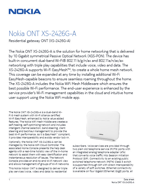
The Nokia ONT XS-2426G-A is a dual-band Wi-Fi 6 mesh system with Wi-Fi Alliance certified Wi-Fi EasyMesh, enhanced by Nokia value added features. The Nokia WiFi Mesh Middleware creates a self-healing, self-optimizing network and includes intelligent channel selection, band steering, client steering and backhaul management to provide the best Wi-Fi performance. As it is EasyMesh ™ compliant, it provides interoperability and avoids vendor lock-in.Optionally, the Nokia ONT XS-2426G-A can be managed by the Nokia WiFi Cloud Controller. The associated Home Console presents the help desk agents with a real-time holistic view of the in-home network to assist them with easy identification and instantaneous resolution of issues. The Network Console provides an end-to-end Wi-Fi network view and allows management of groups of Wi-Fi networks.This Nokia indoor ONT is designed to deliver triple play services (voice, video and data) to residentialNokia ONT XS-2426G-AResidential gateway ONT (XS-2426G-A)The Nokia ONT XS-2426G-A is the solution for home networking that is delivered by 10 Gigabit symmetrical Passive Optical Network (XGS-PON). The device has built-in concurrent dual-band Wi-Fi® 802.11 b/g/n/ax and 802.11a/n/ac/ax networking with triple play capabilities that include voice, video and data. The XS-2426G-A supports Wi-Fi EasyMesh™, to create a whole home mesh network. This coverage can be expanded at any time by installing additional Wi-FiEasyMesh-capable beacons to ensure seamless roaming throughout the home. The XS-2426G-A includes the Nokia WiFi Mesh Middleware which ensures the best possible Wi-Fi performance. The end-user experience is enhanced by the service provider’s Wi-Fi management capabilities in the cloud and intuitive home user support using the Nokia WiFi mobile app.subscribers. Voice services are provided through two plain old telephone service (POTS) ports with an integrated analog telephone adapter (ATA) that converts voice traffic into Session Initiation Protocol (SIP). Connectivity to an existing public switched telephone network (PSTN) Class 5 switch is supported through SIP with direct interoperability of a variety of soft switches. Ethernet connectivityis available on four Gigabit Ethernet (GigE) ports, allof which have the ability to burst up to a full gigabit dynamically. Service providers can deliver video using IP packets (IPTV).Relying on dual-band Wi-Fi allows for support of the widest range of customer products.The IEEE 802.11ax standard enables gigabit speeds on many newer devices, while the widely supported 802.11b/g/n/ac standard can simultaneously connect to legacy devices.Features• Four RJ-45 10/100/1000 Ethernet ports• Two POTS ports for carrier-grade voice services • Dual-band concurrent Wi-Fi: 2.4GHz and 5GHz • Wireless IEEE 802.11 b/g/n/ax: 2.4GHz• Wireless IEEE 802.11ac/ax: 5GHz• Network Address Translation (NAT) and firewall • Voice interworking function from the analog POTS lines to the voice over IP (VoIP) and Ethernet layers• One USB 3.0 host port• Optics support received signal strength indication (RSSI)• Supports virtual private network (VPN) passthrough for Point-to-Point Tunneling Protocol (PPTP), Layer 2 Tunneling Protocol (L2TP) and IPSec• Port forwarding and demilitarized zone (DMZ)/ dynamic domain name system (DDNS) Benefits• Integrates the ONT and wireless access point functions to allow for one less device in the home • Delivers connectivity to Ethernet devices within the home• Comes equipped with Nokia WiFi Mesh Middleware • Supports full triple play services, including voice, video and data• Allows service-per-port configurations • Supports IP video distribution• Supports easy-to-use USB 3.0 connections for external disk drives and home network attached storage (NAS)• Delivers voice services using VoIP• Delivers video services efficiently with multicasting or unicasting• Facilitates network management using Nokia 5520 AMS• Flexible video delivery options of Ethernet or wireless to set-top boxes (STBs) Technical specifications Physical• Height: 195 mm (7.7 in)• Width: 245 mm (9,65 in)• Depth: 37 mm (1.46 in)• Weight: 650g (1.4lb)Installation• Desk mountable• Wall mountable with bracketOperating environment• Temperature: -5°C to 45°C (23°F to 113°F)• Relative humidity: 10% to 90%Power requirements• Local powering with 12 V input (feed uses external AC/DC adapter)• Dying gasp support• Power consumption: <36 WXGS PON uplinks• Wavelength: 1260 nm–1280 nm upstream; 1575 nm–1580 nm downstream• G.9807.1 XGS PON standards compliant: 4 dBm ~ 9 dBm launch power; -28 dBm ~ -9 dBm for receiving• SC/APC connector• 10 G burst mode upstream transmitter• 10 G downstream receiver• G.9807.1-compliant 10 GPON Encapsulation Method (XGEM) framing• Flexible mapping between XGEM ports andT-CONT• Advanced Encryption Standard (AES) 128• Forward error correction (FEC)• Activation with automatic discovered serial number and password• Remote software image download• BOSA On Board (BOB) type laser, SC/APC connectorEthernet interfaces• 10/100/1000Base-T interface with RJ-45 connectors• Wi-Fi Protected Access (WPA) support, including pre-shared key (WPA-PSK), WPA2, WPA3• Forwarding• Ethernet port auto-negotiation or manual configuration with medium dependent interface /medium dependent interface crossover (MDI/ MDIX)• Virtual switch based on IEEE 802.1q virtual LAN (VLAN)• VLAN tagging/de-tagging per Ethernet port and marking/remarking of IEEE 802.1p• IP type of service/differentiated services code point (ToS/DSCP) to IEEE 802.1p mapping for untagged frames• Class of service (CoS) based on VLAN ID, IEEE • 802.1p bit• Internet Group Management Protocol (IGMP)v2/ v3 snooping POTS interfaces• Two FXS ports for VoIP service with RJ-11 connectors• Multiple codecs: ITU-T G.711, ITU-T G.729• SIP (RFC 3261)• ITU-T G.168 echo cancellation• Services: caller ID, call waiting, call hold, 3-way call, call transfer, message waiting indication• 5 ringer equivalence numbers (RENs) per line • Dual-tone multi-frequency (DTMF) dialing• Balanced sinusoidal ring signal, 55 V root mean square (RMS)WLAN interfaces• 2x2 MIMO on 802.11b/g/n/ax• 2x2 MIMO on 802.11a/n/ac/ax• 3 dBi internal antenna• WPA, WPA-PSK/TKIP, WPA2, WPA2-PSK/AES, WPA3• Media access control (MAC) filtersUSB interface• One USB 3.0 interfacesResidential gateways• IPv4 and IPv6• Point-to-Point Protocol over Ethernet (PPPoE) and IP over Ethernet (IPoE)• NAT, DMZ and firewall• Dynamic Host Configuration Protocol (DHCP) and domain name system (DNS) proxy• IGMP proxy• Supports TR-069About NokiaWe create the technology to connect the world. Only Nokia offers a comprehensive portfolio of network equipment, software, services and licensing opportunities across the globe. With our commitment to innovation, driven by the award-winning Nokia Bell Labs, we are a leader in the development and deployment of 5G networks.Our communications service provider customers support more than 6.4 billion subscriptions with our radio networks, and our enterprise customers have deployed over 1,300 industrial networks worldwide. Adhering to the highest ethical standards, we transform how people live, work and communicate. For our latest updates, please visit us online and follow us on Twitter @nokia.Nokia operates a policy of ongoing development and has made all reasonable efforts to ensure that the content of this document is adequate and free of material errors and omissions. Nokia assumes no responsibility for any inaccuracies in this document and reserves the right to change, modify, transfer, or otherwise revise this publication without notice.Nokia is a registered trademark of Nokia Corporation. Other product and company names mentioned herein may be trademarks or trade names of their respective owners.© 2020 Nokia Nokia OY J Karakaari 7 02610 Espoo FinlandLEDs• Power • Link • Auth • LAN (1~4)• TEL (1~2)• VoIP• Wi-Fi Protected Setup (WPS)• WLAN 2.4G/5G • USB • InternetSafety and electromagnetic interference (EMI)• Protection of over voltage/currentRegulatory compliances• CE Mark • FCC Mark。
Mediatek_Wireless_Roadmap-2013-12-27

Confidential BMediaTek Roadmap UpdateDecember/27/2013Copyright © MediaTek Inc. All rights reserved.Confidential BAgenda▪ WiFi Market Update ▪ WiFi Networking Roadmap ▪ Beyond WiFiCopyright © MediaTek Inc. All rights reserved.2013/12/27-2-Confidential BWiFi Market UpdateCopyright © MediaTek Inc. All rights reserved.Smart Phone Say Hello to 802.11acConfidential BHTC New OneSamsung S4Sony Xperia Z Ultra C6802MediaTek13’Feb13’Mar13’Jun14’Q1Copyright © MediaTek Inc. All rights reserved.2013/12/27-4-11n vs. 11ac Transition100% 90% 80% 70% 60% 50% 40% 30% 20% 10% 0% 2013 2014 20152013/12/27 5Confidential BN300 takes entry level positionAC750/AC1200 replace N600 and get growth momentumAC-4SS (DBC) AC-3SS (DBC) AC-2SS (DBC) AC-2SS (FE, DBC) AC-1SS (DBC) 3SS (DBC) 2SS (DBC) 3SS 2SS 1SS20162017Copyright © MediaTek Inc. All rights reserved.Source: ABI, In-Stat, Mediatek IntelligenceMarket Dynamic▪ Router SKU Transition– – – – – –Confidential BN300 replaced N150 as 11n entry level router 11ac DBC router replaced 11n DBC router (AC1200 $79) LTE Smart Phone drive 11ac and NFC demand Normal power router + repeater to extend coverage Router 2.0 - Internet router (public cloud) + home router (personal cloud) Deep Packet Inspection (DPI) becomes mandatory function in mid-/high-end router▪ Next Generation Hotspot (Passpoint R2) moves Wi-Fi to the heart of the carrier network ▪ Home Security & Automation– – – – – Cloud & App, +touch panel for control Surveillance: WiFi Cloud IPC Security: BT Door Lock Home Automation: +Zigbee/Sub-1G for sensor network Healthcare: +BTLE2013/12/27 -6-Copyright © MediaTek Inc. All rights reserved.Confidential BWiFi Networking RoadmapCopyright © MediaTek Inc. All rights reserved.Confidential BAgenda▪ Chip Roadmap ▪ MT7620 Highlights ▪ MT7620 11ac Solutions ▪ MT7621 11ac Solutions ▪ MT7612 11ac SolutionsCopyright © MediaTek Inc. All rights reserved.2013/12/27-8-11n Router RoadmapN600(GbE) N750(GbE) N900(GbE)RT6856 RT3593 RT3593 MT7530 • MIPS34KEc (700 MHz) • DDRI/DDRII, NAND/SPI • FE SW, 802.3az • USB2.0 (2), rGMII, PCIe (2) • IPSec Engine (140Mbps) • AES256-CBC • Storage AcceleratorCPUMPConfidential BMT7620ART3593 MT7530MT7620ART5592 MT7530• MT7530 GbE SW • 5p+2 rGMII • 802.3az EEE • Jumbo FrameN600MT7620ART5592MT7620AMT7530N300MT7620AMT7620N• • • • • • • • • •2x2 802.11n (300 Mbps) MIPS24KEc (580/600 MHz) SDR/DDRI/DDRII, NAND/SPI/SD-XC/eMMC FE SW, 802.3az USB, rGMII(2), PCIe 2Gbps HWNAT (IPv6) Storage Accelerator Lowest Power Consumption Best IOT w/ Intel6300 eCos IPv6 logo ready turnkey (2/8)MT762x• • • • • • • • • •2x2 802.11n (300 Mbps) MIPS24KEc (580 MHz) DDRI/DDRII, SPI/SD-XC/eMMC FE SW, 802.3az USB, PCIe AES128/256-CBC Calibration Free 5V/0.6A power adapter DRAM embedded ULC rBOM, PCBN300GMPQ1’14Q2’14Q3’14Q4’14Q1’15Q2’1511ac Router Roadmap• MIPS1004K dual-core (880MHz) • 256KB L2 • DDRII/DDRIII, NAND/SPI/SD-XC • GbE SW, 802.3az EEE • USB 3.0, USB 2.0, rGMII, PCIe (3) • IPSec Engine (> 400Mbps) • HWNAT(IPv6)+BW Control • Storage Accelerator • NFC: MT6605 • SATAIII(2): 3rd PCIeCPUMPConfidential BAC1750(GbE)MT7621AMT7605E MT7615EAC1200(GbE)MT7621AMT7612E MT7602EMT7602E • LDPC, Beamforming • 256QAMMT7621AMT7612E MT7603EAC1200MT7603E • ULC • MCC • Airtime Fairness • 802.11v, 802.11j • Samples: Q1 2014• 4x4/4SS, 11ac stage2 • LDPC, Beamforming, MU-MIMO • 802.11v, 802.11j • CPU offload • Samples: Q4 2014MT7620AMT7612E• iPA • LDPC, Beamforming • Calibration FreeAC750MT7620AMT7610E• BeamformeeMPQ1’14Q2’14Q3’14Q4’14Q1’15Q2’15Dongle RoadmapAC1300CPUMPConfidential BAC866MT7612U • USB 3.0 • LDPC, Beamforming • Calibration Free, iPAMT7662U • USB 3.0 • BT 4.0+HS, LDPC, Beamforming • Calibration Free, iPA • Linux, Android MT7650U • USB 2.0 • BT 4.0+HS • Beamformee • Linux, AndroidAC433MT7610U • USB 2.0 • BeamformeeN450RT3573N300RT5572 RT5372 • USB 2.0 • Calibration Free, SoftAP mode • QFN40-5x5 (Smallest) MT7670U • USB 2.0 • High Power MT7603U • USB 2.0 • Calibration Free • ULCN150MT7601U RT3070MPQ1’14Q2’14Q3’14Q4’14Q1’15Q2’15PCIe Roadmap>AC1300CPUMPConfidential BMT7615E • 4x4/4SS, 11ac stage2 • LDPC, Beamforming, MU-MIMOAC866MT7612E • LDPC, Beamforming • Calibration Free, iPAAC433MT7610E • BeamformeeN450RT3593 • Calibration Free • LDPC, Beamforming • 256QAM • Calibration Free • 802.11j, 802.11v • 64QAMN300RT5592/EP RT5392MT7602E • USB 2.0 • Calibration Free, SoftAP mode • QFN40-5x5 (Smallest)MT7603EN150MT7601U RT3070MPQ1’14Q2’14Q3’14Q4’14Q1’15Q2’15MT7621 VPN Performance (>400Mbps)Confidential BVPN TunnelLAN:10.10.10.254Encrypti on DES 3DES AES-128 AES-192 AES-256 3DES AES-128 AES-192 AES-256 Authentication SHA-1 MD5 SHA-1 MD5 SHA-1 MD5 SHA-1 MD5 SHA-1 MD5 SHA-1 MD5 SHA-1 MD5 SHA-1 MD5 SHA-1 MD5 DH Group DH2 DH2 DH2 DH2 DH2 DH2 DH2 DH2 DH2 DH2 DH5 DH5 DH5 DH5 DH5 DH5 DH5 DH5NetScreen第一次 第二次 第三次503.963 415.579 450.942 552.657 597.048 546.626 507.185 588.509 422.110 380.032 457.272 455.986 444.925 332.600 448.310 422.465 423.996 505.989 507.322 504.105 421.491 549.283 399.405 395.676 382.091 510.567 398.124 381.551 540.925 508.904 360.313 562.598 420.892 473.680 420.030 472.003 510.725 476.088 517.963 512.740 380.029 502.125 454.674 420.783 557.360 478.124 421.747 552.370TCPTCPTCP平均449.617 465.0827 459.4313 509.5883 509.7547 523.999 474.851 498.975 394.7433 464.2413 436.69 419.44 514.4033 439.876 410.1233 512.4777Copyright © MediaTek Inc. All rights reserved.2013/12/27- 13 -MediaTek Technology RoadmapConfidential B20152014 {BBP} 1. BW 5/10 2. Airtime Fairness {MAC} 1. MCC 2. WiFi Positioning {SoC} KGD2013 {RF} DPD, 11ac iPA {BBP} LDPC, TxBF {MAC} STA-Proxy {SoC} HNAT+HQoS, VPN, Storage AcceleratorCopyright © MediaTek Inc. All rights reserved.{RF} 1. DPA 2. 4x4/4ss, 3. 11ac stage2 {BBP} 1. Smart Antenna v3 2. MU-MIMO2013/12/27- 14 -Software RoadmapReadyOpenWRT trunkOpenWRT (MT7620, 3.x)Confidential B2013 Q1 Q2 Q3 Q4 Q12014 Q2 Q3 Q42015 Q1 Q2●● OpenWRT(MT7620, 2.6.36)(RT5350, 3.x)● OpenWRT● OpenWRT(MT7621, 3.x)Linux SDK● SDK 4.1(MT7620, 2.6.36)● SDK 4.2(MT7621, 2.6.36)● SDK 5.0(Kernel 3.x)eCos OpenBSD● MT7620N/ ● MT7620NMT5350 SDK 2.4.1.4 (2/8M)● AC750 SDK2.4.3.0 (2/16M)● AC750 SDK2.4.5.0 (2/8M)eCos –IPv6 FreeBSD● MT7620N ● AC750 SDK3.0.3.0 (2/8M) - 15 2013/12/27IPv6 SDK 3.0.1.0 (2/16M)IPv6 SDK 3.0.2.0 (2/8M)● AC1200 SDK3.0.4.0 (2/8M)Copyright © MediaTek Inc. All rights reserved.Confidential BSDK 4.2 vs. 4.1 ComparisonSDK 4.1Kernel Chip 2.6.21 2.6.36 (RT6856, MT7620) RT3050, RT3052 RT3883, RT3662 RT3352, RT5350 RT6856, MT7620 GCC 3.4.2SDK 4.22.6.21 2.6.36 (RT6856, MT7620, MT7621) RT3050, RT3052 RT3883, RT3662 RT3352, RT5350 RT6856, MT7620 MT7621 GCC 4.6.3 (MT7621 default) (MT7620 option) uClibc 0.9.33.2 (MT7621 default) (MT7620 option) Fast path (MT7620, MT7621) Fast path (MT7620, MT7621) lighthttpd web server (BSD license) Linux 2.6.36 support 2.6.38 MT7620+MT7530 RT3883+MT7530 WM8960 YES (MT7621) 400Mbps (MT7621) YES xHCI (MT7621) Win8- 16 -DescriptionGccUser LibraryuClibc 0.9.28PPTP L2TP HTTP Server Layer7 QoS Openswan Gigabit Switch Audio DAC HQoS VPN SPDIF USB Windows certificationn/a n/a Go-ahead Linux 2.6.21 only 2.6.22 RT3883+Vitesse WM8750 n/a 150Mbps (RT6856) n/a EHCI (RT6856/MT7620) Vista/Win7MT720 performance gain ~120% MT7620 performance gain ~100% /QDMACopyright © MediaTek Inc. All rights reserved.2013/12/27Value Added SoftwareDPI +iQoS DPI +iQoS (Broadweb) CAPWAP user kernel driverConfidential BSamba, Airplay, Airprint, DLNA DMSVPN NTFS (Paragon) (MediaTek)NTFS (Paragon)Remote USBUSB Printer Audio StorageIPv6 HNAT HQoS (MediaTek)Storage Accelerator (MediaTek)VoW (MediaTek)Mesh (TerraNet)IP cam H.264 (AIT/Sonix) Audio DAC (WM8960)Copyright © MediaTek Inc. All rights reserved.2013/12/27- 17 -Confidential BAgendaChip Roadmap ▪ MT7620 Highlights ▪ MT7620 11ac Solutions ▪ MT7621 11ac Solutions ▪ MT7612 11ac SolutionsCopyright © MediaTek Inc. All rights reserved.2013/12/27- 18 -Confidential BMT7620A Functional Block3.3V 20/40MHz Crystal PMU 2.5/1.0V Clock/Timer/Reset/PLL DRAM Controller NAND/SD-XC/eMMC SPI RF FEM RF FEM MAC BBP UART Full+ UART Lite USB 2.0 Host/Device CTRL/PHY I2C PPE w/ IPv6 I2S PCM 2 3 4 External Interface TransformerSDRAM(512Mbits) DDR1(1Gbits) DDR2(2Gbits) NAND Flash(8Gbits) SPI Flash/Codec UART Interface USB 2.0 Interface EEPROM/Control Audio Interface Codec GPIO/LEDMIPS 24KEc (580/600 MHz) 64K I-Cache 32K D-Cache5G WiFi 2x2 11n: RT5592 2x2 11n: RT5592EP (HP) 3x3 11n: RT3593 1x1 11ac: MT7610ERGMIIPCIe Storage Accelerator Ethernet SwitchRGMII01Copyright © MediaTek Inc. All rights reserved.2013/12/27- 19 -MT7620 Highlights• Best DBC TP w/ Intel 6300 • Best TP w/ mutiSTAs • No. 1 HNAT in smallnetbuilder • First IPv6 HNATConfidential BBest DBC Throughput w/ Intel63002Gbps IPv6 HNATMT7620Lowest Power Consumption• Lowest power consumption • Thermal PK w/ E900USB 2.0 Samba Performance• Perform same performance w/ EA3500 and E4200v2Copyright © MediaTek Inc. All rights reserved.2013/12/27- 20 -HNAT (Chariot) Benchmarkipv6 HNATConfidential B2Gbps HNATOutperform in iPv6 benchmarkCopyright © MediaTek Inc. All rights reserved.2013/12/27- 21 -Confidential BPower Consumption BenchmarkD-LINK DIR-605L RTL8196C+ RTL8192CE 2.31 2.64 1.42 1.38 1.37MT7620NSDRTenda W308R BCM5357TP-LINK TL-WR841N AR9341Uplink Downlink STA associated STA unassociated Radio off1.80 2.18 1.03 0.83 0.613.42 4.41 2.88 2.79 2.072.632 3.290 2.444 2.350 2.068Copyright © MediaTek Inc. All rights reserved.2013/12/27- 22 -Confidential BDBC TP Benchmark (vs. Intel6300)Copyright © MediaTek Inc. All rights reserved.2013/12/27- 23 -Peak Throughput Benchmark APto1STA or APto2STAsConfidential BCopyright © MediaTek Inc. All rights reserved.2013/12/27- 24 -N300/600, AC750/1200(GbE) Solution▪ MT7620A (580MHz)– – – – – 2x2 11n 2.4GHz GbE LAN(4)+WAN USB 2.0, SD-XC, I2S DDR2, SPI Flash PCIe: 802.11 a/n/acMT7620AConfidential B1x1/2x2 11ac▪ MT7530– 5p GbE SwitchMT7530▪ 4L PCB, double sides▪ OS– Linux SDKCopyright © MediaTek Inc. All rights reserved.2013/12/27- 25 -Outdoor AP Solution (Industry Spec.)▪ MT7620A (580MHz)– – – – – 2x2 11n 2.4GHz GbE(2) USB 2.0, PoE DDR1, NAND Flash PCIe• •Confidential BrGMII iNIC802.11 a/n/ac 802.11ac iNICMT7620A– rGMIIPCIe 1x1/2x2 11ac▪ HW Spec.– 4L PCB, double sides – -40~85 degrees (Industry Spec.) – Tx PowerMCS0: 26.8dbm per chain • Over temperature: +- 1dbm•PoE▪ OS– Linux SDKCopyright © MediaTek Inc. All rights reserved. 2013/12/27 - 26 -Confidential BAgendaChip Roadmap MT7620 Highlights ▪ MT7620 11ac Solutions ▪ MT7621 11ac Solutions ▪ MT7612 11ac SolutionsCopyright © MediaTek Inc. All rights reserved.2013/12/27- 27 -AC750 Products▪ Chip: MT7620A+7610EConfidential B▪ MT7620A HNAT, DPD, STA-Proxy, USB performance outperform among all 2x2 11n SoC ▪ eCos IPv6 turnkey for small memory footprint ▪ Shipping AC750 modelsD-Link (DIR-810)Copyright © MediaTek Inc. All rights reserved.IO-Data (WN-AC733GR)2013/12/27 - 28 -PCI (MZK-750DHP)AC750 Solution▪ MT7620A (580MHz)– – – – 2x2 11n 2.4GHz FE LAN(4)+WAN USB 2.0, SD-XC, I2S DDR2, SPI FlashMT7620AConfidential BMT7610E▪ MT7610E– 1x1 11ac (ePA)▪ 4L PCB, double sides▪ Power Consumption– 3.13w (power optimized) – 3.96w (rBOM optimized)▪ OS– Linux SDK – eCos turnkey (2/16)Copyright © MediaTek Inc. All rights reserved. 2013/12/27 - 29 -AC750 vs. HTC New One TP140 120 100 80 60 40 20 0 UplinkCopyright © MediaTek Inc. All rights reserved.Confidential BMbps119.288.890.311ac TPDnlink2013/12/27 - 30 -Bi-directionAC1200(FE) Solution▪ Chip: MT7620A+7612EConfidential B▪ HNAT, DPD, STA-Proxy, USB performance outperform among all 2x2 11n SoC ▪ enable 11ac iPA w/ industry lowest rBOM ▪ support ePA for better coverage ▪ eCos IPv6 turnkey for small memory footprintCopyright © MediaTek Inc. All rights reserved.2013/12/27- 31 -AC1200 Solution▪ MT7620A (580MHz)– – – – 2x2 11n 2.4GHz FE LAN(4)+WAN USB 2.0, SD-XC, I2S DDR2, SPI FlashConfidential BMT7612E▪ MT7612E– 2x2 11ac (iPA/ePA)MT7620A▪ 4L PCB, double sides ▪ Power Consumption– 3.13w (power optimized) – 3.96w (rBOM optimized)▪ OS– Linux SDKCopyright © MediaTek Inc. All rights reserved.2013/12/27- 32 -Confidential BAC1200 iPA Benchmark▪ Tx Power BenchmarkTX output (dBm) MT7612EBelkin AC1000 RTL8197D+ RTL8192ER+ RTL8812AR5GRF HW OFDM HT20 HT40 VHT20 VHT40 VHT80 6M 54M MCS0 MCS7 MCS0 MCS7 MCS0 MCS8 MCS0 MCS9 MCS0 MCS92x2 ac iPA 19 16.5 19 15.5 18.5 15.5 19 15 18.5 15 17.5 152x2 ac ePA 16 14DIR-860 AC1200 (BCM) 2x2 ac ePA 18 16 18 16 18 161218 14Copyright © MediaTek Inc. All rights reserved.2013/12/27- 33 -*TX Pout is single chain data at antenna port which includes 1.5dB loss (transmission line+diplexer+IPEX connector)Confidential BAgendaChip Roadmap MT7620 Highlights MT7620 11ac Solutions ▪ MT7621 11ac Solutions ▪ MT7612 11ac SolutionsCopyright © MediaTek Inc. All rights reserved.2013/12/27- 34 -Confidential BMT7621A Function Block20/25/40MHz Crystal DRAM Controller Clock/Timer/Reset/PLL NAND/SD-XC/eMMC SPI (2)DDR2(2Gbits, 1066) DDR3(4Gbits, 1200) NAND Flash(8Gbits) SPI Flash/Codec UART Interface USB 3.0 Interface USB 2.0 Interface SATA SATAIII (2) Audio Interface NFC MT6605 GPIO/LED11n WiFiPCIeMIPS 1004KEc (880 MHz) 32K I-Cache 32K D-Cache L2-Cache 256KB Storage AcceleratorMIPS 1004KEc (880 MHz) 32K I-Cache 32K D-Cache Cache Coherency Port HNAT+ BW CTRLUART Lite (3) USB 3.0 Host11ac WiFiPCIeUSB 2.0 Host PCIe I2S, PCM, S/PDIFCryptoGigabit SwitchRGMII01234I2C External InterfaceTransformerCopyright © MediaTek Inc. All rights reserved.2013/12/27- 35 -MT7621 ApplicationConfidential BEthernet USB dongle SPDIFeMMC SDXC USB/SATAUSBUSB (printer)Airplay WiFi MT7662 BT Sink play I2C MT6605 PCM (VoIP)I2S I2SSPITouch panelCopyright © MediaTek Inc. All rights reserved. 2013/12/27 - 36 -MT7621N/AMT7621A Package GbE Power Consumption PCB Heat Sink Application TFBGA 11.7x13.6 GbE(5)+rGMII 2.4W 2/4L Yes AC1200G-Router MT7621N TFBGA 11.7x13.6 rGMII 1.2W 2/4L NoConfidential BAC1200-Repeater NAS+GbE(1) AC1200-FE Internet RouterCopyright © MediaTek Inc. All rights reserved.2013/12/27- 37 -Confidential BMT7621 Introduction▪ Platform based network processor for 2x2/3x3 11ac, LTE cat4/5 with rich extensions– Rich I/O sets: 5p GbE switch, rGMII, PCIe(3), USB3, USB2, SD-XC, I2S, PCM, S/PDIF▪ HNAT+BW CTRL can work seamlessly– HNAT w/ 2Gbps wired speed IPv6 routing – HW bandwidth control to replace software scheduler▪ Upgradable L7 QoS database for “Auto QoS” ▪ Storage accelerator – GSO/GRO, fast DMA for write offload ▪ >400 Mbps VPN crypto engine ▪ NFC for WPS replacement ▪ Industry lowest power consumption ▪ World’s first 2x2 11ac iPA to save rBOM ▪ World’s first 2x2 11ac DBC 2L design to save rBOMCopyright © MediaTek Inc. All rights reserved. 2013/12/27 - 38 -AC1200AC1200 -GbE 4L RFB▪ 4L, double side ▪ DDR3 1200/NAND Flash ▪ On board dual band concurrent WIFI– 7612E: 2x2 11ac iPA/iLNA – 7602E: 2x2 11n iPA/iLNAGbE 5p GbEConfidential BU3U2 MT6605 (NFC)IC+ GbE PhyNAND Flash MT7621 A DDR3 (1200)▪ Co-crystal design ▪ External high power module– 7612E: 2x2 11ac – 7602E: 2x2 11n (256QAM) – 7603E: 2x2 11n (64QAM)SD-XCSATA3.0ASM1061 MT7602E (2.4GHz) MT7612E (11ac) S/PDIF▪ USB 3.0/2.0/SATA3.0Copyright © MediaTek Inc. All rights reserved. 2013/12/27 - 39 -*Note: PCB cost estimation by vendor “Newheart”AC1200AC1200 -GbE 2L RFB▪ PCB cost down 40%– Dimension: 168mm x 115mm x 1.6mm – Single side – FR4 PCB: 100pcs estimation – 4Layer:NTD 175 – 2Layer: NTD 105*U 2Confidential B5p GbESD-XC DDR2 (1066)▪ DDR2 800/1066, SPI flash ▪ Co-crystal design ▪ On board dual band concurrent WIFI– 7612E: 2x2 11ac iPA/iLNA – 7602E: 2x2 11ac iPA/iLNAMT7602E (2.4GHz)MT7621ASPI FlashMT7612E (11ac)▪ USB 2.0 HS host supportCopyright © MediaTek Inc. All rights reserved. 2013/12/27 - 40 -MT7621A HDK V31*Note: PCB cost estimation by vendor “Newheart”Benchmark with Dlink DIRDIR-860LBetter computing power Integrated RF front-endConfidential BBenchmark Chip Set AC1200-GbE MT7621A+ MT7612E+MT7602E iPA/iLNA Dual Core 880MHz TX:iPA performance better than competitor ePADlink DIR-860L BCM47081A0+ BCM4352+BCM43217 ePA/eLNA Single Core 800MHz Front-end module:RFMD RFFM4501CPU WIFI 5GMTK AC1200-GbERX:Low rate worst than competitor eLNA 0.5dB High rate better than competitorBetter RF performanceWIFI 2.4GTX:iPA performance better than competitor iPATX:iPARX: Dlink DIR-860L Excellent power consumption Lower thermal risk Cost advantage Power Consumption Thermal r-BOMiLNA better than competitor iLNARX: iLNAUplink: 7.21W Downlink: 7.45W Less heat sink, thermal pad and shielding case USD: 3.8638 Co-clock supportUplink: 9.03W Downlink: 10.98W More thermal strategy USD: 6.5361 w/ RF front-end USD: 5.3967 w/o RF front-endNote: rBOM cost is not including thermal strategy, and shielding case Copyright © MediaTek Inc. All rights reserved. 2013/12/27 - 41 -Benchmark with Netgear R6200v2Confidential BBenchmark Chip Set AC1200-GbE MT7621A+ MT7612E+MT7602E ePA/eLNA Dual Core 880MHz TX:ePA: SKYWORKS SKY85402-11Netgear R6200v2 BCM47081A0+ BCM4352+BCM43217 ePA/eLNA Single Core 800MHz Front-end module:RFMD RFFM4501Better computing power Better RF performance MTK AC1200-GbECPU WIFI 5GRX:eLNASKYWORKS SKY85601-11Better RF performanceWIFI 2.4GFront-end module:RFMD RFFM4203TX:ePA: SKYWORKS SE2528RX: Netgear R6200-V2 Power Consumption Lower thermal risk Cost advantage Thermal r-BOM Less heat sink, thermal pad and shielding case USD:3.8638* Co-clock support USD: 3.9684*eLNA: Richwave RTC6602Uplink: 9.55W Downlink: 12.48W*Note: rBOM cost is not including external RF front-end, thermal strategy, and shielding case Copyright © MediaTek Inc. All rights reserved. 2013/12/27 - 42 -Media Security Gateway (MT7621+STB+ZigBee)Confidential B11n WiFiDDR3 NAND11ac WiFiUSB 2.0 USB 3.0STB SoC (Slave )ASM 1060ZigBeeMT7621 (Host)PCIeHDDSLICUART rGMII Transformer (1000Mps)R J 1 1R J 1 1R J 4 5R J 4 5R J 4 5R J 4 5MocaCopyright © MediaTek Inc. All rights reserved.2013/12/27- 43 -MT762xA + 2.8”(240x320 Dots) TFT +Touch Panel (Resistive (Resistive) )Confidential BCopyright © MediaTek Inc. All rights reserved.2013/12/27- 44 -What’s QoS?▪ End to End ▪ Big Pipe to Small Pie ▪ QoS Components1 Classifier 2 Queue/BW Mgmt 3 Scheduler/ShaperConfidential BCopyright © MediaTek Inc. All rights reserved.2013/12/27- 45 -HWHW-BWBW-CTRL - UpstreamConfidential B1 2 3 4 3 2 1Copyright © MediaTek Inc. All rights reserved.2013/12/27- 46 -HWHW-BWBW-CTRL - DnstreamConfidential B1 2 3 4 3 2 1Copyright © MediaTek Inc. All rights reserved.2013/12/27- 47 -HWHW-BWBW-CTRL – Dnstream (2)1Confidential B2Copyright © MediaTek Inc. All rights reserved.2013/12/27- 48 -USB 3.0 Samba BenchmarkConfidential BAP Linksys EA6400 Buffalo AC1750 D-Link DIR-860L MT7621AFormatHDD Model NameRead (MByte/sec) 13.75Write (MByte/sec) 11.67 15.77test tool InterfaceFAT32Buffalo HD-LB131.45 37.93 72.30IOMETER USB3.0 16.55 29.50Copyright © MediaTek Inc. All rights reserved.2013/12/27- 49 -Confidential BAgendaChip Roadmap MT7620 Highlights MT7620 11ac Solutions MT7621 11ac Solutions ▪ MT7612 11ac SolutionsCopyright © MediaTek Inc. All rights reserved.2013/12/27- 50 -。
NETGEAR AC1200 WiFi 范围扩展器说明书
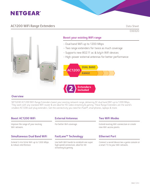
Boost your existing WiFi rangeOverviewNETGEAR AC1200 WiFi Range Extenders boost your existing network range, delivering AC dual band WiFi up to 1200 Mbps. They work with any standard WiFi router & are ideal for HD video streaming & gaming. These Range Extenders are the world’s smallest AC1200 wall-plug extenders. Get the connectivity you need for iPads®, smartphones, laptops & more.• Dual band WiFi up to 1200 Mbps• Two range extenders for twice as much coverage • Supports new 802.11 ac & b/g/n WiFi devices• High-power external antennas for better performanceExtenders IncludedRANGEDUAL BAND AC1200AC1200 WiFi Range Extende r s Data SheetEX6920Simultaneous Dual Band WiFiExtend 2.4 & 5GHz WiFi up to 1200 Mbps & reduce interference.Ethernet PortConnect a wired device like a game console o r a smart TV to your WiFi network.Boost AC1200 WiFiImprove the range of your e xisting WiFi network.Two WiFi ModesExtend existing WiFi connection or create new WiFi access points.FastLane™ TechnologyUse both WiFi bands to establish one superhigh speed connection; ideal for HDstreaming & gaming.External AntennasFor better WiFi coverage.AC1200 WiFi Range Extende r s Data SheetEX6920WiFi Range ExtendersBoost the range of your existing WiFi & create a stronger signal inhard-to-reach areas.Existing WiFiSometimes your router does not provide the WiFicoverage you need.Power on/offEthernet port Secure Connection (WPS)WiFi Range Extenders boost your existing WiFi & deliver greater wireless speed & coverage to where WiFi signals are weak. Improve your home’s WiFi and get better connections for iPads®, smartphones, laptops & more.r s Data Sheet AC1200ExtendeWiFiRangeEX6920 WiFi Analytics AppHow strong is your WiFi signal? Use the NETGEAR WiFi Analytics app & get advanced analytics to optimize your existing or newly extended WiFi network. Check your network status, WiFi signal strength, identify crowded WiFi channels & much more!Here’s what you can do with the WiFi Analytics App!• Get a network status overview• Check WiFi signal strength• Measure WiFi channel interference• Keep track of WiFi strength by location• and more...Scan to install appThis product comes with a limited warranty that is valid only if purchased from a NETGEAR authorized reseller.*24/7 basic technical phone support provided for 90 days from purchase date.¹Works with devices supporting Wi-Fi Protected Setup™ (WPS). Data throughput, signal range, and wireless coverage per sq. ft. are not guaranteed and may vary due to differences in operating environments of wireless networks, including without limitation building materials and wireless interference. Specifications are subject to change without notice. The product may not be compatible with routers or gateways with firmware that has been altered, is based on open source programs, or is non-standard or outdated.NETGEAR, and the NETGEAR Logo are trademarks of NETGEAR, Inc. Mac and the Mac logo are trademarks of Apple Inc. Any other trademarks herein are for reference purposes only. ©2015 NETGEAR, Inc.NETGEAR, Inc. 350 E. Plumeria Drive, San Jose, CA 95134-1911 USA, /supportD-EX6920-0AC1200 WiFi Range Extende r s Data SheetEX6920Package Contents• Two (2) AC1200 WiFi Range Extenders (EX6120)• Quick start guidePhysical Specifications• Dimensions: 55.17 x 67.17 x 39 mm (2.17 x 2.64 x 1.54 in) each • Weight: 130 g (0.29 lb) eachWarranty• /about/warrantySecurity• Wi-Fi Protected Access® (WPA/WPA2–PSK) and WEPStandards• IEEE® 802.11 b/g/n 2.4 GHz • IEEE® 802.11 a/n/ac 5 GHz• One (1) 10/100 Mbps F ast Ethernet port with a uto-sensingtechnologySupport• 24/7 basic technical phone support for 90 daysfrom date of purchaseEase of Use• CD-less setup—great f or mobile devices • Push ‘N’ Connect using Wi-Fi P rotected Setup® (WPS)1System Requirements• 2.4 and/or 5 GHz 802.11 ac & b/g/n wireless router or gateway• Microsoft® Internet Explorer 8.0, Firefox® 20, Safari® 5.1, Google Chrome 25.0 browsers or higher。
7102制冷片参数

7102制冷片参数7102制冷片是一种常见的制冷设备,它通常用于工业、商业和家庭等领域。
它的参数包括多个方面,下面将详细介绍。
首先,7102制冷片的功率参数是关键的指标之一。
功率是制冷片在工作状态下消耗或产生的能量。
该参数通常以瓦特(W)为单位表示。
不同型号的7102制冷片功率范围广泛,可以从几十瓦特到几千瓦特不等。
功率越高,制冷效果越好。
其次,7102制冷片的制冷剂参数也是非常重要的。
制冷剂是实现制冷效果的关键物质,它在制冷过程中吸热并冷却空气。
7102制冷片通常使用一种或多种制冷剂,如氟利昂(Freon),氨(Ammonia)等。
制冷剂的选择要根据具体的应用场景和需求来确定。
第三,7102制冷片的制冷效果参数也需要考虑。
制冷效果是衡量制冷片性能的一个重要指标。
一般来说,制冷效果可以通过两个参数来衡量,即制冷量和制冷效率。
制冷量是制冷片单位时间内制冷的能力,通常以千瓦特(kW)或英国热量单位(British Thermal Units,BTU)表示;制冷效率是指在单位功率下实现的制冷量,通常以COP(Coefficient of Performance)或EER(Energy Efficiency Ratio)表示。
制冷效果越好,制冷片的性能就越高。
此外,7102制冷片的工作温度范围也是一个重要的参数。
不同的应用场景和需求对工作温度有不同的要求。
有些制冷片适用于低温环境,如冷库、冷容器等;而有些则适用于中温或高温环境,如空调、冷水机组等。
7102制冷片通常具有较宽的工作温度范围,可以适应不同温度条件下的使用。
最后,7102制冷片的尺寸和重量参数也需要考虑。
尺寸和重量对于安装和使用来说都是重要的因素。
7102制冷片的尺寸和重量通常会根据不同型号和功率而有所不同。
尺寸较小的制冷片适用于空间有限的场所,如家庭使用,而尺寸较大的则适用于大型商业或工业场所。
综上所述,7102制冷片的参数包括功率、制冷剂、制冷效果、工作温度范围、尺寸和重量等。
美国航空航天Nadcap热处理审核标准AC7102E

型号TYPE: T版次ISSUE: EAC7102Nadcap热处理审核标准(共 171页)AC7102 E 发文单位 DESIGN DEPARTMENT:编 制 DESIGN:审 校 CHECK:审 定 EXAMINE:标 审 STANDARD:总 师 CHIEF OF DEPT.:批 准 APPROVAL:会签单位 JOINT SIGNATURE DEPARTMENT:C EF T Y504F S0157更改标记 MARK发送单号RELEASE SHEET 否.签 字SIG不适用TURE日 期DATE首版日期 1993-06换版日期 2008-09替代 AC7102D2009年2月1日起执行执行性审查学会(PRI)工作程序,特声明:“执行性审查学会PRI出版本报告是为提高技术、工程、和质量科学水平。
本报告的使用完全自愿的,使用者应对它的适用性及在特定条件下使用的合理性,包括因此出现的任何专利侵权承担全部责任。
”执行性审查学会(PRI)欢迎你的书面意见和建议。
版权2007 执行性审查学会版权所有 t-frm-15, 07-01-22161号 Thorn Hill路,Warrendale市,美国宾夕法尼亚州 15086-7527在美国印制Nadcap热处理审核标准1. 给被审查供应商的指导1.1 在正式审查之前1.1.1 供应商应完成如下一系列自查(与之相关的):z AC7102z AC7102/1(如果寻求钎焊认证)z AC7102/2(如果寻求铝合金热处理认证)z AC7102/3(如果寻求渗碳认证)z AC7102/4(如果寻求渗氮认证)z AC7102/5(如果为检验热处理质量,进行硬度试验)z AC7101/3(如果为检验热处理质量,进行抗拉试验)z AC7101/4(如果为检验热处理质量,进行金相试验)z AC7102/S(如果寻求主要的特性认证)正式的审查之前,所有的不符合项应采取纠正行动来纠正完毕。
FP7102规格书

We2 Recommended Operating Conditions
Parameter
Supply Voltage Operating Temperature
Symbol
VIN
Conditions
Min.
3.6 -25
0. 25V
500
Output Drive Control Circuits
COMP
Internal Soft Start Circuit
Thermal Shutdown
GND
GND
LX
LX
This datasheet contains new product information. Feeling Technology reserves the rights to modify the product specification without notice. No liability is assumed as a result of the use of this product. No rights under any patent accompany the sales of the product.
Typ.
Max.
28 85
Unit
V ℃
DC Electrical Characteristics (VCC=6V, TA= 25℃, unless otherwise noted)
Parameter Reference
Output Voltage Input Regulation Output Voltage Change with Temperature VREF FB connected to COMP 0.245 0.25 2 1 1 320 5 5 0.255 12.5 2 2 V mV % △VREF VCC=3.6 V to 25 V △VREF / TA=-25℃ to 25℃ VREF TA= 25℃ to 85℃ f Δf / ΔV VCC=3.6V to 25V Δf / ΔT TA = -25℃ to +85℃
Nighthawk AC1900 WiFi LTE模式路由器R7100LG用户指南说明书

Do MoreWiFi Network Name and PasswordThe preassigned WiFi network name (SSID) and password (network key) are unique to your modem router, like a serial number. Because the modem router automatically uses WiFi security, you don’t need to set it up. The WiFi settings are on the label on the modem router.We recommend that you use the preassigned WiFi settings becauseyou can check the label if you forget them. You can also log in to the modem router to change these settings. If you do so, write down the new WiFi settings and store them in a safe place.You can write the WiFi settings from the label on your modem router in this space for easy reference. If you change the WiFi settings, write the new settings here for easy reference and store this booklet in a safe place.WiFi network name (SSID):Network key (password):Check the 3G/4G LED BehaviorThe 3G/4G LED on your modem router indicates your modem router’s mobile broadband signal strength.If your modem router is connected to a 4G network, the 3G/4G LED lights the following colors:If your modem router is connected to a 3G network, the 3G/4G LED lights the following colors:For information about the other LED behaviors, see the user manual, which is available online at .Connect Your Modem Router to a Modem You can connect your modem router to a cable or fiber modem. If you insert a micro SIM card into your modem router and you also connect a modem to the Internet port on the modem router, you can set up failover mode on your modem router. For more information, see Set Up Failover Mode on page 13.¾To connect your modem router to a modem and connect it to the Internet:1. Attach and position the antennas:2.a. Unplug your modem, remove and replace the backup battery if ituses one, and then plug the modem back in.b. Use the Ethernet cable to connect the modem to the yellowInternet port on the modem router.c. Connect the modem router to a power source.The modem router’s Power LED lights amber and then turns whitewhen the modem router is ready.3. Connect to the Internet:modem router.To connect with WiFi, do the following:a. Make sure that the modem router’s WiFi LED is lit.b. Find the modem router’s preassigned WiFi network name andpassword on the label on the modem router.c. Open the WiFi connection manager on a WiFi-enabled computeror mobile device, find the modem router’s WiFi network name,and use the modem router’s password to connect.d. Launch a web browser.If the NETGEAR installation assistant does not display, visit. If a login window opens, enter admin forthe user name and password for the password.e. Follow the NETGEAR installation assistant.The Internet LED lights when the modem router is connectedto the Internet.Join the WiFi NetworkYou can either use Wi-Fi Protected Setup (WPS) or select yourmodem router’s WiFi network and type its password.Join the WiFi Network Using WPSFor help with the WPS button on your WPS-enabled device, check the instructions or online help that came with that WPS-enabled device. Some older equipment cannot use WPS.¾To join the network using WPS:1. Press the WPS button on the modem router for three to five seconds.The WPS LED on the modem router blinks white.2. Within two minutes, on your WPS-enabled device, press its WPSbutton or click its onscreen WPS button.The WPS LED on the modem router lights solid white when theWPS-enabled device connects to your modem router.3. Repeat this process to add other WPS-enabled devices.Join the WiFi Network Using theModem Router’s WiFi SettingsUse the modem router’s WiFi network name and password to connect your WiFi-enabled computer or mobile device to the modem router’s network through WiFi. If you did not change the modem router’s WiFi network name and password, use the modem router’s preassigned WiFi network name and password, which are on the label on the modem router.¾To select your network and enter its password:1. On your WiFi-enabled computer or mobile device, open the WiFiconnection manager that manages your WiFi connections.The WiFi connection manager scans for WiFi networks in your area. 2. Find and select your modem router’s WiFi network name (SSID).The SSID is on the label on the modem router.3. Enter the modem router’s password (or your custom password if youchanged it).The password is on the label on the modem router.4. Repeat Step 1 through Step 3 to add other WiFi-enabled computer ormobile device.View or Change theModem Router SettingsAfter you use the NETGEAR installation assistant to set up themodem router, you can log in to the modem router to view or change its settings.Log In to the Modem Router¾To log in to the modem router:1. Connect a computer or mobile device to the modem router.You can connect using a wired connection or a WiFi connection:• To connect using a wired connection, use an Ethernet cable (not included) to connect an Ethernet port on your computer to anEthernet port on the modem router.• To connect using a WiFi connection, find the modem router’s preassigned WiFi network name and password on the label onthe modem router. Open the WiFi connection manager on yourWiFi-enabled computer or mobile device, find the modem router’sWiFi network name, and use the modem router’s password toconnect.2. Launch a web browser and visit .A login window opens.3. Enter admin for the user name and password for the password.The BASIC Home page displays.Change the WiFi Network Name and Password The router’s preset WiFi network name (SSID) and password are on the label on the router. If you want to change your router’s WiFi network name and password, log in to the modem router.¾To change the router’s WiFi network name and password: 1. Launch a web browser from a computer or mobile device that isconnected to the network and visit .A login window opens.2. Enter the modem router user name and password.The user name is admin and the default password is password. Use the default credentials if you did not change them.The BASIC Home page displays.3. Select Wireless.The Wireless Setup page displays.4. To change the WiFi network name (SSID), enter a new name in theName (SSID) field.5. To change the WiFi password, enter a new password in the Password(Network Key) field.6. Click the Apply button.Your settings are saved.Change the admin Password¾To change the admin password:1. Launch a web browser from a computer or mobile device that isconnected to the network and visit .A login window opens.2. Enter admin for the user name and password for the password.The BASIC Home page displays.3. Select ADVANCED > Administration > Set Password.The Set Password page displays.4. Type your old password and type the new password twice.5. To be able to recover the password, select the Enable PasswordRecovery check box.We recommend that you enable password recovery.6. Select two security questions and provide answers to them.7. Click the Apply button.Your settings are saved.Recover a Forgotten admin PasswordThe default password for the admin user name is password. If you changed the password and enabled the password recovery feature, you can retrieve this password.¾To retrieve a forgotten admin password:1. Launch a web browser from a computer or mobile device that isconnected to the network and visit .A login window opens.2. Click the Cancel button.If password recovery is enabled, you are prompted to enter the serial number of the modem router. The serial number is on the label on the modem router.3. Enter the serial number of the modem router.4. Click the Continue button.A page displays requesting the answers to your security questions.5. Enter the saved answers to your security questions.6. Click the Continue button.A page displays your recovered password.7. Click the Login again button.A login window opens.8. With your recovered password, log in to the modem router.Set Up Failover ModeIf you inserted a micro SIM card into your modem router and you also connected a modem to the Internet port on the modem router, you can set up failover mode on your modem router. Failover mode allows your modem router to switch to a mobile broadband connection if its Internet port connection fails. Note that the modem router’s Internet port is also referred to as a WAN Ethernet port.¾To set up failover mode:1. Connect a modem to the Internet port on your modem routerand insert a micro SIM card into the SIM slot on the back of themodem router.2. Set up your modem router’s WAN Ethernet connection:a. Launch a web browser from a computer or mobile device that isconnected to the network and visit .A login window opens.b. Enter the modem router user name and password.The user name is admin and the default password is password.Use the default credentials if you did not change them.The BASIC Home page displays.c. Select ADVANCED > Setup > Broadband Settings.The Broadband Settings page displays.d. In the Internet Connection Mode menu, select Always useEthernet connection to enable the Internet port’s (also referredto as a WAN Ethernet port) Internet connection only.e. Click the Apply button.Your settings are saved.f. Select ADVANCED > Setup > Internet Setup.The Internet Setup page displays.g. Specify your Internet connection settings.h. Click the Apply button.Your settings are saved.i. Test your modem router’s Internet connection to make sure thatyour modem router can connect to the Internet.3. Set up your modem router’s mobile broadband connection:a. Log back in to the modem router.The BASIC Home page displays.b. Select ADVANCED > Setup > Broadband Settings.The Broadband Settings page displays.c. In the Internet Connection Mode menu, select Always useMobile Broadband connection to enable the mobile broadbandconnection only.d. Click the Apply button.Your settings are saved.e. Select ADVANCED > Setup > Mobile Broadband Settings.The Mobile Broadband Settings page displays.f. Specify your mobile broadband connection settings.g. Click the Apply button.Your settings are saved.h. Test your modem router’s Internet connection to make sure thatyour modem router can connect to the Internet.4. Set the failover mode:a. Log back in to the modem router.The BASIC Home page displays.b. Select ADVANCED > Setup > Broadband Settings.The Broadband Settings page displays.c. In the Internet Connection Mode menu, select Use WANEthernet with mobile as back up in case of failure.The modem router will connect to the Internet using the WANEthernet connection. If the WAN Ethernet connection fails, themodem router will connect to the Internet using the mobilebroadband connection.d. Click the Apply button.Your settings are saved.If your modem router is connected to a mobile broadband network, you can log in to the modem router to check the status of the mobile broadband connection.¾To check the mobile broadband status:1. Launch a web browser from a computer or mobile device that isconnected to the network and visit .A login window opens.2. Enter the modem router user name and password.The user name is admin and the default password is password. Use the default credentials if you did not change them.The BASIC Home page displays.3. Click the ADVANCED tab.4. In the Internet Port pane, click the Connection Status button.The Mobile Broadband Status page displays.If your modem router is connected to a mobile broadband network, you can log in to the modem router and view the mobile broadband settings, such as the APN, PDP type, and network mode.¾To view the mobile broadband settings:1. Launch a web browser from a computer or mobile device that isconnected to the network and visit .A login window opens.2. Enter the modem router user name and password.The user name is admin and the default password is password. Use the default credentials if you did not change them.The BASIC Home page displays.3. Select ADVANCED > Setup > Mobile Broadband Settings.The Mobile Broadband Settings page displays.Access a USB Device on the Network ReadySHARE lets you access and share a USB storage device connected to the modem router’s USB ports. (If your USB device uses special drivers, it is not compatible.)¾To access the USB storage device from a Windows computer:1. Connect your USB storage device to a USB port on the modem router.We recommend that you use the blue USB 3.0 port on themodem router to get the best USB device access speed.When you connect the USB storage device to the modem router’s USB port, it might take up to two minutes before it is ready for sharing. By default, the USB storage device is available to all computers on your local area network (LAN).2. On a Windows computer that is connected to the network, selectStart > Run, enter \\readyshare in the dialog box, and click the OK button.A window displays the files and folders on the device.¾To access the USB storage device from a Mac:1. Connect your USB storage device to a USB port on the modem router.We recommend that you use the blue USB 3.0 port on themodem router to get the best USB device access speed.When you connect the USB storage device to the modem router’s USB port, it might take up to two minutes before it is ready for sharing. By default, the USB storage device is available to all computers on your local area network (LAN).2. On a Mac that is connected to the network, launch Finder and selectGo > Connect to Server.The Connect to server window opens.3. Enter the smb://readyshare in the Server Address field and clickthe Connect button.4. When prompted, select the Guest radio button.5. If you set up access control on the modem router and you allowedyour Mac to access the network, select the Registered Userradio button and enter admin for the name and password for thepassword.For more information about access control, see the user manual,which is available online at or through a link in the modem router’s user interface.6. Click the Connect button.A window displays the files and folders on the device.NETGEAR, Inc.350 East Plumeria DriveSan Jose, CA 95134, USA NETGEAR INTL LTD Building 3, University Technology CentreCurraheen Road, Cork, IrelandSupportThank you for purchasing this NETGEAR product. You can visit /support to register your product, get help, access the latest downloads and user manuals, and join our community. We recommend that you use only official NETGEAR support resources.Trademarks© NETGEAR, Inc., NETGEAR and the NETGEAR Logo are trademarks of NETGEAR, Inc. Any non-NETGEAR trademarks are used for reference purposes only.ComplianceFor the current EU Declaration of Conformity, visit /app/answers/detail/a_id/11621/.For regulatory compliance information, visit /about/regulatory/.See the regulatory compliance document before connecting the power supply.。
- 1、下载文档前请自行甄别文档内容的完整性,平台不提供额外的编辑、内容补充、找答案等附加服务。
- 2、"仅部分预览"的文档,不可在线预览部分如存在完整性等问题,可反馈申请退款(可完整预览的文档不适用该条件!)。
- 3、如文档侵犯您的权益,请联系客服反馈,我们会尽快为您处理(人工客服工作时间:9:00-18:30)。
PRI operating procedures provide that "This report is published by PRI to advance the state of technical, engineering, and quality sciences. The use of this report is entirely voluntary, and its applicability and suitability for any particular use, including any patent infringement arising therefrom, is the sole responsibility of the user."PRI invites your written comments and suggestions.Copyright 2009 Performance Review Institute. All rights reserved. t-frm-15 21-May-08161Thorn Hill RoadWarrendale, PA 15086-7527AUDIT CRITERIAAC7102/2 REV . BIssued 2006-10Revised 2009-8Superseding AC7102/2 Rev. ABaselineNadcap AUDIT CRITERIA For ALUMINUM HEAT TREATINGTO BE USED FOR AUDITS CONDUCTED ON OR AFTER JANUARY 31, 20101. Facilities 1.1 Are the heat treating equipment and instruments for the heat treatment ofaluminum alloys in accordance with all the customers’ requirements?YES NO 1.2 Do the heat treating facilities possess the correct temperature uniformity,instrument accuracy and resolution for the heat treating of aluminum alloys in accordance with all the customers’ requirements?YES NO 2. Control of Heating Environment above 400F (200C) NA2.1 Are the furnaces used above 400F (200C) designed and operated such that theproducts of combustion that could contaminate the load do not enter the heat treating furnaces for finished parts?YES NO2.2 When required, is there a procedure that includes the use of protective compounds(ammonium or sodium fluoborate, or other equivalent moisture reducingcompound), or the replacement of protective compounds with the monthly check for high temperature oxidation?YES NO NA2.2.1 Are there records indicating that the procedure is followed? YES NO NA3. Salt Baths NA3.1 Does certification exist to document compliance to material specification for gradeof salt required by applicable heat treating specification?YES NO3.2 Do the records indicate that each salt bath is tested periodically for pH inaccordance with the applicable heat treating specification? YES NO4. Racks, Fixtures and Baskets NAYES NO4.1 Do the procedures and records indicate that specially designed racks and fixturesare used for the specific parts they are designed for?YES NO4.2 Do the procedures specify that racks, fixtures and/or baskets shall be free fromentrapped quenchant?4.3 Are there procedures, racking sketches or other means to ensure that parts areYES NOspaced adequately to ensure adequate circulation of the heating medium andquenchant?NO 4.4 Is there evidence that the procedures are being followed? YESYES NO4.5 Do the racks, fixtures and baskets appear to be in good condition and suitable fortheir intended use?System NA5. Quench5.1 Are the quench mechanisms and other mechanical equipment (hoists, trucks,YES NOrollers, etc.) operational and capable of meeting the maximum quench delayprovisions of the specifications?5.2 Do the procedures and records indicate that quench delay requirements are metYES NOfor each individual load?6. Spray Quench/Forced Air Quench NA6.1 Is the spray or forced air quenching only used on those alloys and product formsYES NOwhen allowed by the governing specification?YES NO6.2 Are there records to document the qualification of spray and/or forced airquenching equipment?YES NO6.3 Are the periodic electrical conductivity tests performed to verify the effectiveness ofthe spray and/or forced air quench as required by the governing specification?YES NO6.4 Is there a maintenance plan in place to assure that nozzles and jets are notblocked and are oriented at the same position as qualified?YES NO6.5 Is the tensile testing performed at the correct frequency (i.e. qualification, lot,periodic, etc.) as required by the governing specification?7. QuenchantControl NAYES NO7.1 Do the procedures specify how quenchant temperature is to be controlled anddocumented?YES NO7.2 Do the records on or traceable to the traveler demonstrate that quenchants havebeen at the specified temperature before and after the parts were quenched?7.3 Do the procedures and observations indicate that quenchant agitation and/orYES NOagitation of the parts during quenching conform to applicable specifications?8. Water/Polymer Quenchant Solutions NA8.1 Is there a vendor’s qualification report on file, including certificates for each lot,YES NOwhich demonstrates that the polymer quenchant solutions being used foraluminum alloys conforms to the requirements of AMS 3025 and/or applicablecustomers’ specifications?8.2 Is there a system in place that ensures that the quenching in water/polymerYES NOsolution is only used when permitted by the particular customer and specificationfor the specific alloy and metal thickness?8.3 Is there a procedure that specifies that all the water/polymer quenchant solutionsYES NOare checked for concentration by a method and at frequencies required by thecustomer?8.4 Are there records to document that all the water/polymer quenchant solutions haveYES NObeen checked for concentration by a method and at frequencies required by thecustomer?YES NO8.5 If the concentration is checked by the refractive index, is the refractometerperiodically calibrated using standard solutions?9. Water/Polymer Quenchant used in conjunction with the Salt Baths NA9.1 Is there a method to ensure that the water/polymer quenchant solutions, used inYES NOconjunction with the salt baths are checked weekly for salt contamination usingcalibrated known solutions?9.1.1 Do the records show that the contamination does not exceed 6%? YES NO10. Refrigeration NA10.1 Do procedures address cooling requirements after quench? YES NO10.1.1 Are there records to show that the cooling after quench is in compliance withYES NOcustomer requirements specified in procedures or shop planning?YES NO10.2 Do procedures specify the requirements for time/temperature limits for retention ofthe “As Quenched” condition?10.3 Do procedures address the recording of the temperature in each refrigeration orYES NOcold storage unit?NO 10.4 Do the records indicate that the procedures are followed? YES11. HandlingFasteners NAYES NO 11.1 Do procedures address the customers’ requirements for special handling of thefasteners after quenching?12. Aluminum Solution Heat Treating Furnaces with the Heat Source in Walls NA 12.1 Are radiant tubes and/or electric heating elements shielded or positioned toYES NO prevent the radiation heating of parts?12.2 Are the radiation tests made in accordance with AMS 2750 prior to initialYES NO production use and after any repair or adjustments that might alter radiationcharacteristics?Testing NA 13. Conductivity13.1 Conductivity Inspector / Operator Training13.1.1 Are the personnel that perform conductivity testing trained andYES NO qualified/certified per the internal procedure that meets the applicablecustomers’ specifications?YES NO 13.1.1.1 Do procedures require personnel performing tests to demonstrate operationand standardization as part of qualification?13.1.2 Do records indicate that personnel performing conductivity are trained toYES NO supplier procedures?13.2. Calibration of Conductivity Test Equipment NANote: As it applies to this section, calibration is defined as the periodicinstrument calibration to national standards.YES NO 13.2.1 Do records indicate the conductivity measurement instrument meetcustomer requirements for accuracy, readability, and repeatability?13.2.1.1 Do procedures define the required instrument accuracy, readability,YES NO repeatability per customer requirements?13.2.2 Do records indicate the instrument calibration oscillator frequency meetYES NO customer requirements?13.2.2.1 Do procedures define the instrument oscillator frequency settings forYES NO calibration per customer requirements?13.2.3 Do records indicate calibrations are performed at the required testYES NO intervals per customer requirements?YES NO13.2.3.1 Do procedures define the required calibration intervals (period betweencalibrations) per customer requirements?13.2.4 Do procedures address calibration standards and their accuracy? YES NO13.2.4.1 Do records indicate calibration standard conformance? YES NO13.2.4.2 Are the working and/or laboratory standard calibration blocks properlyYES NO maintained, protected from damage and available in appropriate IACS (MS/m –MegaSiemens/meter) ranges for the material inspected or instruments to becalibrated?YES NO NA 13.2.4.3 If used at the supplier, do the laboratory standard calibration blocks have valuesassigned in accordance with ASTM B-193, or the values for the laboratorystandard calibration blocks assigned by an independent agency usingstandards traceable to a national standard?13.3 Standardization of Conductivity Test EquipmentNote: As it applies to this section, Standardization is defined as the in-useworking verification performed by operators.YES NO13.3.1 Do supplier procedures and/or work instructions require operatorstandardization upon start of testing and define a re-standardization intervalthereafter?YES NO13.3.1.1 Does the defined standardization test interval comply with customerrequirements?13.3.2 Are working standards properly maintained and protected from damage? YES NOYES NO13.3.2.1 Are working standards available in the appropriate IACS (MS/m) ranges for thematerial inspected and the instruments to be calibrated?YES NO13.3.2.2 Do procedures define the appropriate IACS (MS/m) ranges in accordance withcustomer requirements?13.4 Performance of Conductivity Testing13.4.1 Is there controlled documentation (procedure, job traveler, drawing, etc.) tospecify the following?a. The selection and number of test locations?YES NOb. Effect and control of thin gauge and / or clad aluminum?YES NOYES NOc. Effect and control of curvature, edge effect, minimum surfacearea, and other part geometry concerns?d. Operating frequency and probe size?YES NOe. Test instrument, standard, and part temperature stabilization?YES NOf. Sample Size YES NO13.4.2 Are acceptance criteria accurately flowed down to the inspector/operator? YES NO13.4.3 Does documented objective evidence show conductivity meetsYES NO acceptance criteria?YES NO 13.4.4 Are the tested values recorded individually or as a range for the lot (not as anaverage)?13.4.5 Auditor shall verify the following: YES NOa. Operators are performing standardizations at instrument start-upYES NO and frequency defined.b. Tests are taken at sufficient locations, including extremes of metalYES NO thickness.c. Apparent conductivity tables are properly utilized for clad and thinYES NO gauge alloys.d. Controls on curvature, edge effect, and/or minimum surface area areYES NO observed during testing.e. Test instrument, standards and parts are stabilized to the sameYES NO temperature before testing.f. The oscillator frequency of the conductivity instrument isYES NO appropriate for the apparent conductivity tables being utilized; aswell as the material form & thickness being tested.g. Number of parts tested conforms to requirements (e.g. sample size)?YES NO14. Testing NA 14.1 Do the procedures identify the periodic testing required by customer to verify theYES NO aluminum heat treating (e.g. monthly quench effectiveness testing - tensiletesting, eutectic melting, intergranular corrosion, clad diffusion, etc.)?YES NO 14.2 Is there objective evidence that the supplier’s periodic testing is performed perthe procedures and the customers’ requirements?YES NO14.3 Are the specifications required sample sizes (or 100%) and acceptance rangesfor hardness testing or conductivity testing of each order of parts listed on theplanning or on the controlled media traceable to the individual part number?15. Compliance Audits of Completed Heat Treating Jobs15.1 The Auditor shall complete the long form job audits based on the supplier’s heattreating capabilities. In some cases, no aluminum long job audits may berequired. For a supplier that performs only aluminum heat treating, two (2) longform job audits are required.16. Abbreviated Job Audits Checklist16.1 The Auditor shall complete short form job audits based on the supplier’s heattreating capabilities. Usually, a minimum of two (2) job audits will be required foranyone seeking aluminum heat treating accreditation. For a supplier that performsonly aluminum heat treating, a minimum of eight (8) job audits are required,preferably for in-process parts. When sufficient in-process jobs cannot bewitnessed, completed jobs may be substituted.。