0805共模电感规格书
DCM2012-201-2P共模电感规格书
DCM4532[1812 inch]DCM3225[1210 inch]DCM2520[1008 inch]DCM2012[0805 inch]*DCM series•All specifications are subject to change without notice.•Conformity to RoHS Directive: This means that, in conformity with EU Directive 2002/95/EC, lead, cadmium, mercury, hexavalent chromium, and specific bromine-based flame retardants, PBB and PBDE, have not been used, except for exempted applications.Common Mode FiltersFor high-speed differential signal line/general signal line Type:* Dimensions Code [EIA](6) internal codeDCM4532DCM3225DCM2520DCM2012DCM Series DCM2012, 2520, 3225, 4532DCM 2012 -900-2P -T Common Mode FiltersFor High-speed Differential Signal Line / General Signal LineFEATURES•Although greatly miniaturized, this wire-wound chip-type filter maintains the characteristics needed for a common mode filter. Common mode impedance is 1000Ω [at 100MHz], so this filter is greatly effective in supporting noise.•Almost no affect upon even high speed signals since differential mode impedance is kept low.•This series includes both 2-line and 3-line types. They are used for various types of circuits and noise.APPLICATIONS•Used for radiation noise suppression for any electronic devices. •Used to counter common mode noise affecting signals within high-speed lines.•USB line for personal computers and peripheral equipment. •IEEE1394 line for personal computers, DVC, STB, etc.•LVDS, panel link line for liquid crystal display panels.TEMPERATURE RANGESPACKAGING STYLE AND QUANTITIESPRODUCT IDENTIFICATION (1) Series name(2) Dimensions L ×W 2012: 2.0×1.2mm(3) Impedance[at 100MHz]900: 90Ω(4) Number of line2P: 2-line 3P: 3-line(5) Packaging styleT: ø180mm reel taping TL: ø330mm reel taping RECOMMENDED SOLDERING CONDITIONS RECOMMENDED TEMPERATURE PROFILE FOR LEAD-FREE SOLDERREFLOW PROFILE FOR SOLDER HEAT RESISTANCEConformity to RoHS Directive Operating–25 to +85°C Storage(After mount)–25 to +85°CPackaging styleT ype Reel QuantityT apingø180mm 2000 pieces/reel ø330mm 10000 pieces/reel ø180mm 2000 pieces/reel ø330mm 10000 pieces/reel ø180mm 1000 pieces/reel ø330mm 5000 pieces/reel ø180mm 500 pieces/reel ø330mm2000 pieces/reel(1)(2)(3)(4)(5)(6)DCM2520-3P DCM4532-102-3PDCM2520-2P DCM3225-2PDCM2012-2PSHAPES AND DIMENSIONS/CIRCUIT DIAGRAMS/RECOMMENDED PC BOARD PATTERNS 2-LINE TYPE 3-LINE TYPEDCM4532-102-3P10000.6200.2DCM2520-801-3P 800 1.6200.15DCM3225-102-2P 10000.5200.2DCM3225-271-2P 2700.3200.3DCM3225-161-2P 1600.2200.35DCM3225-800-2P 800.15200.4DCM2520-102-2P 10000.9200.2DCM2520-601-2P 6000.45200.3DCM2520-451-2P 4500.4200.35DCM2520-301-2P 3000.35200.4DCM2012-361-2P 3600.5500.22DCM2012-201-2P 2000.25500.35DCM2012-121-2P 1200.22500.37DCM2012-900-2P 900.19500.4ELECTRICAL CHARACTERISTICSPart No.Impedance(Ω)typ.[100MHz]DC resistance(Ω)max.[per 1 line]Rated voltage Edc(V)max.Rated current Idc(A)max.2-LINE3-LINEDCM3225-271-2P DCM3225-102-2PDCM3225-800-2P DCM3225-161-2PDCM2520-601-2P DCM2520-102-2PDCM2520-301-2P DCM2520-451-2PDCM2012-201-2P DCM2012-361-2PDCM2012-900-2P DCM2012-121-2PMEASURING CIRCUITS 2-LINEDCM2520-801-3P DCM4532-102-3PIMPEDANCE vs. FREQUENCY CHARACTERISTICS 3-LINEMEASURING CIRCUITS 3-LINE。
共模电感原厂规格书
DCM4532[1812 inch]DCM3225[1210 inch]DCM2520[1008 inch]DCM2012[0805 inch]*DCM series•All specifications are subject to change without notice.•Conformity to RoHS Directive: This means that, in conformity with EU Directive 2002/95/EC, lead, cadmium, mercury, hexavalent chromium, and specific bromine-based flame retardants, PBB and PBDE, have not been used, except for exempted applications.Common Mode FiltersFor high-speed differential signal line/general signal line Type:* Dimensions Code [EIA](6) internal codeDCM4532DCM3225DCM2520DCM2012DCM Series DCM2012, 2520, 3225, 4532DCM 2012 -900-2P -T Common Mode FiltersFor High-speed Differential Signal Line / General Signal LineFEATURES•Although greatly miniaturized, this wire-wound chip-type filter maintains the characteristics needed for a common mode filter. Common mode impedance is 1000Ω [at 100MHz], so this filter is greatly effective in supporting noise.•Almost no affect upon even high speed signals since differential mode impedance is kept low.•This series includes both 2-line and 3-line types. They are used for various types of circuits and noise.APPLICATIONS•Used for radiation noise suppression for any electronic devices. •Used to counter common mode noise affecting signals within high-speed lines.•USB line for personal computers and peripheral equipment. •IEEE1394 line for personal computers, DVC, STB, etc.•LVDS, panel link line for liquid crystal display panels.TEMPERATURE RANGESPACKAGING STYLE AND QUANTITIESPRODUCT IDENTIFICATION (1) Series name(2) Dimensions L ×W 2012: 2.0×1.2mm(3) Impedance[at 100MHz]900: 90Ω(4) Number of line2P: 2-line 3P: 3-line(5) Packaging styleT: ø180mm reel taping TL: ø330mm reel taping RECOMMENDED SOLDERING CONDITIONS RECOMMENDED TEMPERATURE PROFILE FOR LEAD-FREE SOLDERREFLOW PROFILE FOR SOLDER HEAT RESISTANCEConformity to RoHS Directive Operating–25 to +85°C Storage(After mount)–25 to +85°CPackaging styleT ype Reel QuantityT apingø180mm 2000 pieces/reel ø330mm 10000 pieces/reel ø180mm 2000 pieces/reel ø330mm 10000 pieces/reel ø180mm 1000 pieces/reel ø330mm 5000 pieces/reel ø180mm 500 pieces/reel ø330mm2000 pieces/reel(1)(2)(3)(4)(5)(6)DCM2520-3P DCM4532-102-3PDCM2520-2P DCM3225-2PDCM2012-2PSHAPES AND DIMENSIONS/CIRCUIT DIAGRAMS/RECOMMENDED PC BOARD PATTERNS 2-LINE TYPE 3-LINE TYPEDCM4532-102-3P10000.6200.2DCM2520-801-3P 800 1.6200.15DCM3225-102-2P 10000.5200.2DCM3225-271-2P 2700.3200.3DCM3225-161-2P 1600.2200.35DCM3225-800-2P 800.15200.4DCM2520-102-2P 10000.9200.2DCM2520-601-2P 6000.45200.3DCM2520-451-2P 4500.4200.35DCM2520-301-2P 3000.35200.4DCM2012-361-2P 3600.5500.22DCM2012-201-2P 2000.25500.35DCM2012-121-2P 1200.22500.37DCM2012-900-2P 900.19500.4ELECTRICAL CHARACTERISTICSPart No.Impedance(Ω)typ.[100MHz]DC resistance(Ω)max.[per 1 line]Rated voltage Edc(V)max.Rated current Idc(A)max.2-LINE3-LINEDCM3225-271-2P DCM3225-102-2PDCM3225-800-2P DCM3225-161-2PDCM2520-601-2P DCM2520-102-2PDCM2520-301-2P DCM2520-451-2PDCM2012-201-2P DCM2012-361-2PDCM2012-900-2P DCM2012-121-2PMEASURING CIRCUITS 2-LINEDCM2520-801-3P DCM4532-102-3PIMPEDANCE vs. FREQUENCY CHARACTERISTICS 3-LINEMEASURING CIRCUITS 3-LINE。
0805尺寸规格的说明
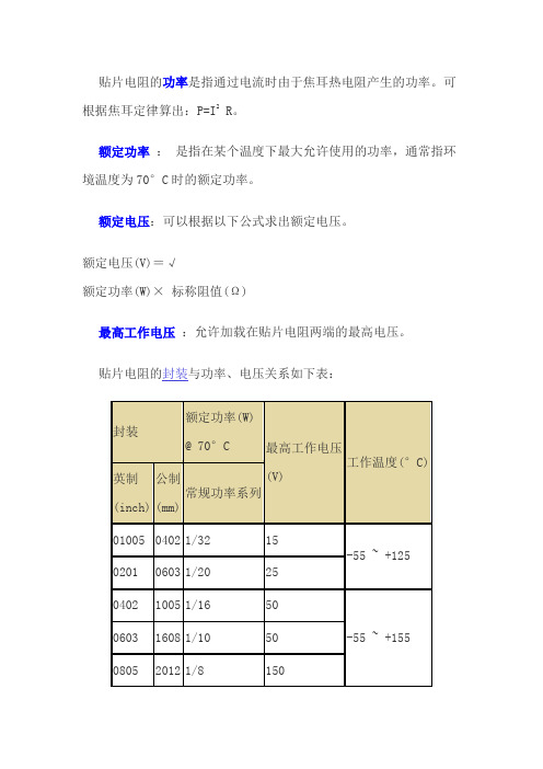
贴片电阻的功率是指通过电流时由于焦耳热电阻产生的功率。
可根据焦耳定律算出:P=I2 R。
额定功率:是指在某个温度下最大允许使用的功率,通常指环境温度为70°C时的额定功率。
额定电压:可以根据以下公式求出额定电压。
额定电压(V)=√额定功率(W)× 标称阻值(Ω)最高工作电压:允许加载在贴片电阻两端的最高电压。
贴片电阻的封装与功率、电压关系如下表:图1 (-55 ~+125)功率及环境温度降额曲线图图2 (-55 ~+155)功率及环境温度降额曲线图注意事项:•设计和使用贴片电阻时,最大功率不能超过其额定功率,否则会降低其可靠性。
•一般按额定功率的70%降额设计使用。
•也不能超过其最大工作电压,否则有击穿的危险。
•一般按最高工作电压的75%降额设计使用。
•当环境温度超过70°C,必须按照降额曲线图(图1,图2)降额使用。
我们俗称的封装是指英制。
规格书//电容规格书.pdf贴片电阻常见封装有9种,用两种尺寸代码来表示。
一种尺寸代码是由4位数字表示的EIA(美国电子工业协会)代码,前两位与后两位分别表示电阻的长与宽,以英寸为单位。
我们常说的0603封装就是指英制代码。
另一种是米制代码,也由4位数字表示,其单位为毫米。
下表列出贴片电阻封装英制和公制的关系及详细的尺寸:英制(inch ) 公制(mm)长(L)(mm)宽(W)(mm)高(t)(mm)a(mm)b(mm)02010603 0.60±0.050.30±0.050.23±0.050.10±0.050.15±0.0504021005 1.00±0.100.50±0.100.30±0.100.20±0.100.25±0.1006031608 1.60±0.150.80±0.150.40±0.100.30±0.200.30±0.2008052012 2.00±0.201.25±0.150.50±0.100.40±0.200.40±0.2012063216 3.20±0.201.60±0.150.55±0.100.50±0.200.50±0.201210 322 3.20±0. 2.50±0.0.55±0.0.50±0.0.50±0.Note:我们俗称的封装是指英制。
贴片压敏电阻0805封装参数型号规格书大全

UN Semiconductor Co., Ltd.
Revision December 18, 2013
3/5
@ UN Semiconductor Co., Ltd. 2013
MULTILAYER CHIP VARISTORS
UN0805-XXXH Series
Packaging Specification
hours, the change of varistor voltage shall be within 10%.
Damp Heat Load/ Humidity Load
The specimen should be subjected to 40℃,90 to 95%RH environment, and the maximum allowable voltage applied for 1000 hours, then stored at room temperature and humidity for one or two hours. The change of varistor voltage shall be within 10%.
machine. And a normal paper tape shall be connected in the head of taping for the operator handle.
type
0402 0603 0805 1206 1210 1812 2220 3220
A0 ±0.10
1.08
B0
K0
±0.10 ±0.10
1.88 1.04
T ±0.05 0.22
T2
D0
±0.05 +0.10
电感选型规范2

电感器选型规范
一、 选型原则
1.0 总则 1.0.1 电感器在MRP II 中从3个分类(1001~1003)改变为7个分类(1001~1007):
1001 高频插装电感(固定插装) 1002 可变电感(感值可变,插装或贴片) 1003 片状电感(固定贴片) 1004 共模电感(插装或贴片) 1005 空心线圈 (插装或贴片) 1006 工频功率电感(固定插装) 1007 EMI磁珠(插装或贴片) 1.0.2 在MRP II 中,优选等级用M标记的项目限制在公司电气使用,用T标记的项目 限制在话机中使用。 在公司技术的产品中均不使用上述标记的项目。 1.0.3 电感器的归一化方向为: (1)1001类插装固定电感器将淘汰小电流项目,用1003贴片固定电感器替代,保留 功率型电感。 (2)1003类片状电感器逐步向小型化、叠层化方向发展。 优选库将适应发展方向 而动态调整,这类电感器是通用小电流电感器的优选器件。 (3)1002类可变电感,包括中周和可调线圈,数量少, 只给出目前的优选库。 (4)1004类功率型优选插装,信号型优选表面贴。 (5)1005类主要用于微调,高频使用项目逐步淘汰,中低频使用保留。 (6)1006类是用硅钢片制作的,只能用于工频范围,目前只有MBC采用。 (7)尽量采用网上器件,严格控制新器件数量的增长 (8)不论那种电感器,都不能采用边缘极限规格。
电感器选型规范
c.额定上限工作温度:优选130 ℃等级的材料,即B CLASS。 d.抗电强度: 线圈与磁芯之间施加1500V,50Hz电压,持续时间1min,漏电流要小于1mA,无 击穿和飞弧; e.优选结构类型:工字电感优选。色环电感将逐步淘汰。 对于功率型电感,虽然PULSE、COILCRAFT和TDK有表面贴型产品,但考虑到 目前成本相差太大,以插装为优选。 f.优选磁芯:考虑到成本问题,非标准产品请尽量选用国产磁芯。 g.对公司电气的自设计或公司技术委托公司电气设计用于电源的电感器,根据具 体情况可以不受以上电感标称值限制。具体设计规范按照公司电气《电磁元件外协加 工技术规范》、《电感器设计工艺规范》进行。
国巨电阻规格书
ELECTRICAL CHARACTERISTICS Table 2
CHARACTERISTICS POWER OPERATING TEMPERATURE RANGE MAXIMUM WORKING VOLTAGE MAXIMUM DIELECTRIC OVERLOAD WITHSTANDING VOLTAGE VOLTAGE RESISTANCE RANGE TEMPERATURE COEFFICIENT JUMPER CRITERIA
SCOPE This specification describes RC series chip resistors with lead free terminations made by thick film process. APPLICATIONS All general purpose application
CONSTRUCTION The resistor is constructed on top of a high-grade ceramic body. Internal metal electrodes are added on each end to make the contacts to the thick film resistive element. The composition of the resistive element is a noble metal imbedded into a glass and covered by a second glass to prevent environmental influences. The resistor is laser trimmed to the rated resistance value. The resistor is covered with a protective epoxy coat, finally the two external terminations (matte tin on Nibarrier) are added, as shown in Fig.4.
PSS系列贴片功率电感规格书
【 南京南山半导体有限公司 — 风华高科贴片功率电感选型资料】
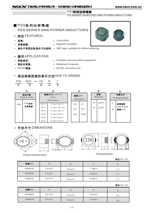
PSS PS SERIES SHIELDED SMD POWER INDUCTORS
PSS PSS SERIES SMD POWER INDUCTORS FEATURES
0.040 0.044 0.059 0.065 0.085 0.128 0.180 0.250 0.300 0.390 0.700 0.800 1.68
PS5030 Series
Part Number PSS5030-1R2NT PSS5030-2R2NT PSS5030-3R3NT PSS5030-4R7NT PSS5030-6R8NT PSS5030-100MT PSS5030-150MT PSS5030-220MT PSS5030-330MT PSS5030-470MT PSS5030-680MT PSS5030-101MT PSS5030-151MT PSS5030-221MT H 1.2 2.2 3.3 4.7 6.8 10 15 22 33 47 68 100 150 220 Tolerance 30% 30% 30% 30% 30% 20% 20% 20% 20% 20% 20% 20% 20% 20% Test Freq. 100kHz 100kHz 100kHz 100kHz 100kHz 100kHz 100kHz 100kHz 100kHz 100kHz 100kHz 100kHz 100kHz DCR( )Max Isat(A) 3.50 3.30 2.20 2.05 1.85 1.45 1.25 1.00 0.85 0.70 0.45 0.45 0.38 0.20
电感的封装形式
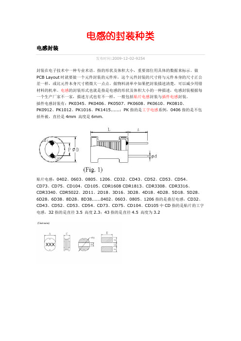
电感的封装种类电感封装发布时间:2009-12-02-9254封装在电子技术中一种专业术语。
指的形状及体积大小,重要部位用具体的数据来标示。
做PCB Layout时就要做一个元件封装的元件库,这个元件封装的尺寸将与元件本身的尺寸正公差一样,或比元件本身尺寸稍微大一点点。
做物料清单中如果把封装描述清楚,可以减少用错材料的机率。
电感的封装形式也就是指是电感的形状及体积大小的一种描述,电感封装根据每一个生产厂家不一家,描述方式也有不一样,一般包括贴片电感封装与插件电感封装。
插件电感封装有:PK0345、PK0406、PK0507、PK0608、PK0610、PK0810、PK0912、PK1012、PK1016、PK1415......;PK指的是工字电感系例,0406指的是不包括外被,直径是4mm 高度是6mm.贴片电感:0402、0603、0805、1206、CD32、CD43、CD52、CD53、CD54、CD73、CD75、CD104、CD105、CDR1608 CDR1813、CDR3308、CDR3316、CDR3340、CDR5022、2D11、2D18、3D16、3D28、4D18、4D28、5D18、5D28、6D28、6D38、8D28、8D38......0402、0603、0805、1206指的是叠层电感,CD32、CD43、CD52、CD53、CD54、CD73、CD75、CD104、CD105中CD指的是贴片的工字电感,32指的是直径3.5 高度2.3;43指的是直径4.5 高度为3.2贴片电感封装尺寸发布时间:2014-11-29-6668贴片电感封装尺寸SHAPES AND DIMENSIONS(形状及尺寸)(Unit:m/m)贴片电感封装尺寸列表绕线贴片电感封装发布时间:2010-10-17-2900绕线贴片电感封装SHAPES AND DIMENSIONS(形状及尺寸)(Unit:m/m)绕线贴片电感封装列表工字电感封装尺寸发布时间:2014-11-28-9062工字电感封装尺寸图SHAPES AND DIMENSIONS(形状及尺寸)(Unit:m/m)工字电感封装尺寸列表卧式工字电感尺寸发布时间:2010-10-17-2241卧式工字电感尺寸图SHAPES AND DIMENSIONS(形状及尺寸)(Unit:m/m)卧式工字电感尺寸列表色环电感封装尺寸发布时间:2010-10-17-3013色环电感封装尺寸SHAPES AND DIMENSIONS(形状及尺寸)(Unit:m/m)色环电感封装尺寸列表环形电感封装尺寸发布时间:2014-11-28-564环形电感封装尺寸:三脚电感封装尺寸发布时间:2014-11-28-2954三脚电感封装尺寸SHAPES AND DIMENSIONS(形状及尺寸)(Unit:m/m)东莞市欣永电子有限公司为你提供三脚电感封装尺寸及三脚电感封装尺寸图介绍等资料.功率电感封装发布时间:2010-12-25-4100功率电感封装SHAPES AND DIMENSIONS(形状及尺寸)(Unit:m/m)尺寸图表:贴片功率电感封装尺寸发布时间:2010-10-17-6730贴片功率电感封装尺寸SHAPES AND DIMENSIONS(形状及尺寸)(Unit:m/m)贴片功率电感封装尺寸列表大功率屏蔽电感封装发布时间:2010-10-17-3844大功率屏蔽电感封装SHAPES AND DIMENSIONS(形状及尺寸)(Unit:m/m)大功率屏蔽电感封装列表D系列屏蔽贴片电感封装尺寸发布时间:2014-09-08-4233屏蔽电感封装SHAPES AND DIMENSIONS(形状及尺寸)(Unit:m/m)2D11/2D14/2D18/3D11/3D14/3D16/3D284D14/4D18/4D22/4D28/5D18/5D28/6D26/6D388D28/8D38/8D43屏蔽电感封装列表UU系列共模电感封装尺寸发布时间:2014-11-19-724UU系列共模电感封装尺寸下载:•UU9.8共模电感封装尺pdf文档•UU10.5共模电感封装尺pdf文档•UU16共模电感封装尺pdf文档贴片排珠封装发布时间:2010-10-05-1613贴片排珠封装图:shapes and dimensions 形状与尺寸in:mm(供PCB layout参考)贴片排珠封装列表贴片磁珠封装发布时间:2010-10-05-3593贴片磁珠封装:1005(0402)、1608(0603)、2012(0805)、3216(1206)、3225(1806)、4532(1812)shapes and dimensions形状及尺寸in mm(供PCBlayout参考)贴片磁珠封装列表:穿芯磁珠尺寸发布时间:2010-10-18-2388穿芯磁珠尺寸图SHAPES AND DIMENSIONS(形状及尺寸)(Unit:m/m)穿芯磁珠尺寸列表。
- 1、下载文档前请自行甄别文档内容的完整性,平台不提供额外的编辑、内容补充、找答案等附加服务。
- 2、"仅部分预览"的文档,不可在线预览部分如存在完整性等问题,可反馈申请退款(可完整预览的文档不适用该条件!)。
- 3、如文档侵犯您的权益,请联系客服反馈,我们会尽快为您处理(人工客服工作时间:9:00-18:30)。
A
B
Epoxy
C
Terminations Wires
①
④
(0.4)
②
(0.45)
(0.4)
③
(0.45)
Equivalent circuit
①
④
②
③
No Polarity
A : 2.0 ± 0.2 B : 1.2 ± 0.2 C : 1.2 ± 0.2
Drawn by Checked by Approved by
(1) Product name (2) Shapes and dimensions (3) Shielding Type (4) Impedance【 at 100MHz】
900:90Ω (5) Number of Line
2P:2-Line (6) Taping Type
3. Shapes and Dimensions [Dimensions in mm]
Measurement terminal
①
④
②
③
PRODUCT SPECIFICATION
5.Reliability Test
6/10 SPEC. NO.
T-0602-001T
Operating temperature : -25 to +85℃
Storage temp and humidity : 20~25℃ ,60%RH max.
1000 100
CMF2012F-400-2P-T
Common Mode Differential Mode
Insulation Resistance (MΩ)Min.
10 10 10 10 10 10 10 10 10 10 10 10 10 10 10 10
Impedance(Ω) Impedance(Ω)
Item
Specifications
Test conditions
Solder
It can be connected on the
Apply cream solder to the test circuit board .
ability
Recommendation soldering conditioIt is mounted on the recommendation soldering condition.
Common-Mode Impedance
Z(Ω) at 100MHz 30 ±25% 40 ±25% 67 ±25% 75 ±25% 90 ±25% 120±25% 160±25% 180±25% 200±25% 220±25% 260±25% 370±25% 600±25% 900±25% 1000±25% 2200±25%
PRODUCT SPECIFICATION
SPEC. NO. T-0602-001T
7/10
Item
Specifications
High
Appearance : Ferrite shall not be
temperature damaged.
resistance
initial value.
insulation resistance: >10(MΩ)
1000 100
CMF2012F-121-2P-T
Common Mode Differential Mode
10
1
0.1 1
10
100
1000
Frequency(MHz)
1000 100
CMF2012F-201-2P-T
Common Mode Differential Mode
10
1
1
10
100
1000
This specification applies ferrite Chip common mode filters CMF2012F-Series to be delivered to user.
2. Product Identification
CMF 2012 F - 900 - 2P - T (1) (2) (3) (4) (5) (6)
PRODUCT SPECIFICATION
2/10 SPEC. NO.
T-0602-001T
4. Electrical Characterisitics
4-1 Electrical Spec.
Our Product Part Number
CMF2012F-300-2P-T CMF2012F-400-2P-T CMF2012F-670-2P-T CMF2012F-750-2P-T CMF2012F-900-2P-T CMF2012F-121-2P-T CMF2012F-161-2P-T CMF2012F-181-2P-T CMF2012F-201-2P-T CMF2012F-221-2P-T CMF2012F-261-2P-T CMF2012F-371-2P-T CMF2012F-601-2P-T CMF2012F-901-2P-T CMF2012F-102-2P-T CMF2012F-222-2P-T
PRODUCT SPECIFICATION
尚越
CUSTOMER'S PRODUCT NAME:
EMTEK PRODUCT NAME:
CMF2012F-900-2P-T
THIS SPECIFICATION IS:
□ FULLY ACCEPTED
□ DENIED
□ ACCEPTED UNDER THE FOLLOWING CONDITIONS
Dip pads in flux and dip in solder pot( 96.5 Sn/3.5 Ag
solder) at 255°C ±5°C.
Terminal The terminal electrode and the ferrit Solder a chip to test substrate , and then laterally apply a
10000 1000
CMF2012F-371-2P-T
Common Mode Differential Mode
100
10
1
0.1 1
10
100
1000
Frequency(MHz)
1000 100
CMF2012F-261-2P-T
Common Mode Differential Mode1011 Nhomakorabea10
Frequency(MHz)
Impedance(OHM)
10000 1000 100
10 1 0.1
1
CMF2012F-181-2P-T
Common Mode Differential Mode
10
100
Frequency(MHz)
Impedance(OHM)
10000 1000 100
10 1 0.1
SPEC. NO: T-0602-001T DATE: Jul.2,2009
SIGNATURE: NAME(PRINT): TITLE:
DATE:
本文件內容全部或部份,未經兆欣科技股份有限公 司同意不得以任何形式複製或其他用途 All rights reserved.This document or parts thereof,may not be reproduced by any means or used in any manner witout written permission of EMTEK CO.,LTD.
FACTORY: 39,Chingao Rd.,(305)Hsinpu, Hsinchu Hsien,Taiwan,R.O.C TEL: 03-5894-433 FAX: 03-5894-523
PRODUCT SPECIFICATION
1/10 SPEC. NO.
T-0602-001T
1. Scope
1
CMF2012F-261-2P-T
Common Mode Differential Mode
10
100
Frequency(MHz)
1000 1000
Impedance(OHM)
PRODUCT SPECIFICATION
4/10 SPEC. NO.
T-0602-001T
Impedance(OHM)
10
10
1
1
0.1 1
10
100
1000
Frequency(MHz)
0.1 1
10
100
1000
Frequency(MHz)
PRODUCT SPECIFICATION
3/10 SPEC. NO.
T-0602-001T
CMF2012F-670-2P-T
1000
Common Mode
Differential Mode 100
DC resistance : standard value
Humidity inside.
resistance
Thermal shock
Test conditions
Temperature : +85±2℃ Applied voltage : Rated voltage Applied current : Rated current Testing time : 50±12 hours Measurement : After placing for 24 hours min.
Common Mode Differential Mode
100
10
1
1
F1r0equency(MH10z0)