共模电感MTC100604-105T 立式
Unigear 550产品样本

主母线系统接地车,无关合能力
电缆接地车,无关合能力
7
金属铠装
3
静触头盒和活门
主开关通过静触头盒内的静触头分别与母线室和电缆室相连。静触头盒互相分立。 主开关的活门用金属板制成。当主开关从试验位置进入工作位置时,活门可自 动打开;当主开关从工作位置到达试验/隔离位置时,活门自动关闭并被闭锁。
电缆
电缆室内可连接单芯或三芯电缆。每相所能连接电缆的芯数取决于电缆的额定 电压、电缆室外的尺寸以及电缆分叉部位。 由于电缆易于在柜前安装,因此开关设备可靠墙安装。
Unigear 550 型铠装式金属封闭开关设备
额定电流:630~2000A
目录
1. 概述 ....................................................3 2. 空气绝缘 ................................................5 3. 金属铠装 ................................................7 4. 安全 ....................................................9 5. 辅助手车 ...............................................10 6. 试验 ...................................................12 7. 内部故障电弧防护 .......................................14 8. 真空断路器 .............................................16 9. 互感器 .................................................18 10. 接地开关 ..............................................19 11. 保护和控制系统 ........................................20 12. 典型方案及技术数据 ....................................21 13. 主结线方案 ............................................24 14. 开关柜布置及安装 ......................................37 15. 订货须知 ..............................................39
100a 共模电感

100a 共模电感
100a共模电感是一种电子元件,用于电路中的共模抑制和滤波。
它是由一对线圈组成的,线圈中的导线通常是绝缘的,以防止电流泄漏。
在电子电路中,共模信号是指两个信号在同一时间和相同方向上发生的信号。
而共模电感的作用就是通过将共模信号引导到地面,从而减少或消除共模干扰。
共模电感的名称中的100a指的是它的额定电流。
这意味着共模电感可以承受高达100安培的电流。
这使得它在高功率电子设备中广泛应用,如电力变换器、交流电机驱动器和电源滤波器等。
共模电感的工作原理是利用线圈中的磁场来抑制共模信号。
当共模信号通过共模电感时,电感中的磁场会产生一个反向的电势,从而减弱或抵消共模信号。
这样,只有差模信号能够通过电路,而共模信号被有效地抑制了。
除了抑制共模信号外,共模电感还可以用于滤波。
它可以通过选择合适的电感值和频率特性来滤除特定频段的信号。
这在音频设备和通信系统中非常有用,可以提高信号质量和抑制干扰。
100a共模电感是一种重要的电子元件,用于共模抑制和滤波。
它通过引导共模信号到地面,减少或消除共模干扰。
它的高额定电流和灵活的频率特性使其在各种电子设备中得到广泛应用。
无论是在电
力变换器中还是在音频设备中,共模电感都发挥着重要的作用,提高信号质量并减少干扰。
爱立信LGE360032ZGG电子模具电路保护器商品说明书

Eaton LGE360032ZGGEaton Series G electronic molded case circuit breaker, LG-frame, LG, Complete breaker, Digitrip 310 RMS, Electronic LSI trip, Three-pole, 600A, 65 kAIC at 240 Vac, 35 kAIC at 415 Vac, 35 kAIC at 480 Vac, 18 kAIC at 600 Vac, Line/loadGeneral specificationsEaton Series G electronic molded case circuit breakerLGE360032ZGG 7866854380235.48 in 5.48 in 5.48 in 16 lb Eaton Selling Policy 25-000, one (1) year from the date of installation of theProduct or eighteen (18) months from thedate of shipment of the Product,whichever occurs first.CE Marked CSA CertifiedIEC RatedUL Listed LG breaker is HACR ratedProduct NameCatalog NumberUPCProduct Length/Depth Product Height Product Width Product Weight WarrantyCompliancesCertificationsCatalog NotesMetric35 kAIC at 415 Vac65 kAIC at 240 Vac35 kAIC at 480 Vac18 kAIC at 600 Vac Complete breakerLGLGComplete breakerLine and load600 Vac600 AElectronic LSIZone selective interlock Three-pole Application of Tap Rules to Molded Case Breaker Terminals Application of Multi-Wire Terminals for Molded Case Circuit BreakersMulti-wire lugs product aidCircuit breaker motor operators product aidCurrent limiting molded case circuit breaker module for series G, JG and CL310+ MCCB product family pocket folderPlug-in adapters for molded case circuit breakers product aid StrandAble terminals product aidMotor protection circuit breakers product aidHigh performance operating handles for Series G circuit breakers product aidMolded case circuit breakers providing higher levels of selective coordination product aidPower metering and monitoring with Modbus RTU product aidSeries G MCCB quick selectorCurrent limiting molded case circuit breaker module product aid Comprehensive circuit protection for control panel applicationsBreaker service centersJ-Frame 310+ and L-Frame 310+ Molded-case circuit breakersEaton's Volume 4—Circuit ProtectionMolded case circuit breakers catalogInstallation Instructions for Series G L-Frame Circuit BreakersMOEM MCCB product selection guideEaton Specification Sheet - LGE360032ZGGNG and ND-Frame molded case circuit breakersL-Frame 310+ Molded-case circuit breakers 100A-600AMounting hardware Interrupt ratingTypeFrameCircuit breaker type Circuit breaker frame type TerminalsVoltage rating Amperage RatingTrip Type CommunicationNumber of poles Application notesBrochuresCatalogsInstallation instructions Specifications and datasheetsEaton Corporation plc Eaton House30 Pembroke Road Dublin 4, Ireland © 2023 Eaton. All Rights Reserved. Eaton is a registered trademark.All other trademarks areproperty of their respectiveowners./socialmedia。
克罗韦尔 PowerFlex 6000T 10 kV R 框架中压交流变频器 数据表

技术数据PowerFlex 6000T 10 kV R 框架中压交流变频器编号 6000T-R主题⻚码变更摘要2产品目录号说明3技术规格4标准和认证5尺寸6产品选型表6PowerFlex 6000T 10 kV R 框架变频器选型7电缆注意事项9电源接线考量因素9电机电缆规格10控制信号线接线考量因素10常规导线类别10线路和负载电缆线规11选择编码器(选配)11变频器转矩能力13变频器选件13其他资源51PowerFlex 6000T 10 kV R 框架中压交流变频器技术数据变更摘要本出版物中包含以下新增内容或更新信息。
该列表仅列出了主要更新,并未反映出所有变更。
主题⻚码更新了概述3更新了变频器规格表:•额定功率范围•输出频率范围•机柜•机械结构涂层5更新了变频器选型表:•PowerFlex 6000T-R 10 kV 50 Hz 变频器 — 标准负载(IEC 认证)•PowerFlex 6000T-R 10 kV 50 Hz 变频器 — 重载(IEC 认证)8 92罗克⻙尔⾃动化出版物 6000-TD101B-ZH-P - 2023 年 2 月罗克⻙尔⾃动化出版物 6000-TD101B-ZH-P - 2023 年 2 月3PowerFlex 6000T 10 kV R 框架中压交流变频器技术数据概述PowerFlex® 中压变频器系列提供多种变频器和选件,可满足您的应用性能需求。
PowerFlex 6000 变频器适合各种应用项目,包括⻛机、泵、压缩机、传送带和铣床。
PowerFlex 6000T-R 10 kV 50 Hz 变频器适用于全新和改装应用项目,为 10 kV 时功率为 280 kW 到 3,550 kW 的电机控制应用项目提供解决方案。
⻛冷式 PowerFlex 6000T 10 kV R 变频器通过实现标准负载与重载应用的软启动和变速控制,最大程度地提高能效。
PowerFlex 6000T-R 10 kV 50 Hz 交流变频器在各种应用项目中都能实现灵活性,可根据电机电压提供多种配置,满足 IEC 和 GB 要求。
江苏省计量检定收费标准版
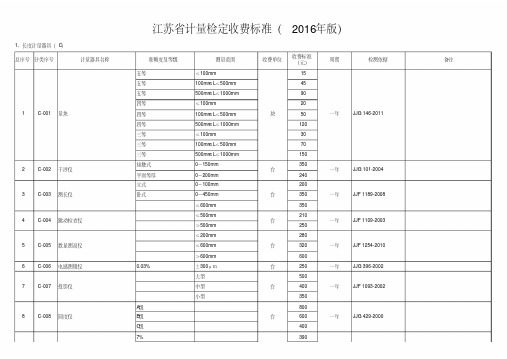
0~1000mm 0~2000mm 0~3000mm (200 ×100)mm (50 ×125)mm (75 ×150)mm (50 ×13)mm
0~6mm
1.0 μm以下 (1.0 ~50.0) μm
0~180mm 0~500mm 0~250mm 0.2um 1.0um ±100分度 0o~360° 0o~360°
38 C-038 高度游标卡尺 39 C-039 齿厚卡尺 40 C-040 塞尺 41 C-041 测厚仪
42 C-042 标准厚度片 43 C-043 刮板细度计
准确度及等级
4级, 5级 低,中,高级
(0.02 ~3.0)mm 超声测厚仪 涡流测厚仪 机械式测厚仪 1/100h (0 ~150)μm 工作
一年
一年 一年 一年 一年 一年 一年
检测依据 JJG 35-2006
JJG 379-2009
JJG 201-2008 JJG 201-2008 JJG 201-2008 JJG 201-2008 JJF 1254-2010 技术说明书
一年
JJG 21-2008
一年 一年
一年
JJF 1207-2008 JJF 1207-2008
一年
JJF 1189-2008
一年
JJF 1109-2003
一年
JJF 1254-2010
一年
JJG 396-2002
一年
JJF 1093-2002
一年
JJG 429-2000
备注
总序号 分类序号
计量器具名称
9
C-009 电动轮廓仪
10 C-010 气动量仪 11 C-011 样板
12 C-012 测长机
DELTA2000 10 kV自动化电感因数测试设备说明书

DELTA200010 kV Automated Insulation Power Factor Test SetnDesigned to work in high interference switchyards of up to 765 kVnBuilt-in capability for storing, printing and downloading test resultsnRugged, portable design for field/shop shop use with automated control via the PowerDB™ software packagenOptional module for LV 3-phase TTR testing and excitation current up to 500 mA (via PowerDB)nOptional HV reference capacitors(100 pF, 1000 pF) with 2% dissipation fac-tor, and a 10 nF HV TTR capacitornOptional Priority Access package offering exclusive services/support (US market only)DELTA200010 kV Automated Insulation Power Factor Test SetDESCRIPTIONThe DELTA2000 is a fully automatic 10 kV insulation power factor test set designed for condition assessment of electrical insulation in high voltage apparatus such as transformers, bushings, circuit breakers, cables, lightning arresters and rotating machinery.This set has been designed to provide a comprehensive AC insulation diagnostic test. Measurements are performed au-tomatically by the DELTA2000, and results are displayed on a large graphical LCD. Measured quantities include voltage, current, power (loss), power factor and capacitance. The operator has the option of correcting the current and loss readings to their 2.5 kV or 10 kV equivalents.The built-in tracking automatic interference suppression circuit ensures accurate and reliable test results undersevere electrostatic and electromagnetic interference condi-tions. This feature allows the performance of test measure-ments in energized switchyards of up to 765 kV.The operator has the option of storing the test results on the provided data key, or download directly to a PC or the included thermal printer. A small printer mounting can be installed inside the unit’s lid in lieu of the standard printer that is included. The data key has storage capacity for 127 sets of test results. Information stored on the data key can be easily retrieved on a PC using the provided software program and interface box.In addition to performing insulation power factor tests, the DELTA2000 can be used for measuring the excitation cur-rent of transformer windings.The Priority Access program provides specific guaranteed support to assure full utilization of the MeggerDELTA2000. The purchase of the program entitles the user free services for one year from receipt of the unit. FEATURES AND BENEFITSn Fully automatic operation eliminates operator error and reduces testing time.nSimplified operation procedure eliminates the need for extensive software or hardware setups.nPerforms all standard ungrounded-specimen tests (UST) and grounded-specimen tests (GST), with or without a guard circuit.nUtilizing the automatic suppression circuitry achieves high accuracy measurement under severe electrostatic and electromagnetic interference conditions.nTwo-piece design reduces size and weight of the system and provides easier transportation.n Built-in self diagnostic and calibration check.nThe operator has the option of measuring either the power factor or dissipation factor (tan ∂).1981DELTA2000 10 kV Automated Insulation Power Factor Test Setn Open-ground detector ensures proper grounding before test.n Interlock switches provide operator safety.n High accuracy SF6 gas-filled capacitor as internal refer-ence.n Built-in interface to the optional Resonating Inductor (Cat. No. 670600) to extend the capacitance measuring range to 1.1µF at 10 kV.n Data key stores 127 sets of test results for retrieval and analysis. Stored results can be easily transferred to a PC using the provided interface box.n Optional printer mounting inside unit’s lid instead of standard thermal printer.n Optional HV TTR capacitor (10 nF) in addition to two HV reference capacitors (100 pF and 1000 pF) with a2% dissipation factor.n Optional module to perform LV three-phase transformer turns ratio testing and excitation current up to 500 mA in accordance with Megger TTR300 product specifications (via PowerDB software).n RS-232 serial interface for downloading the test results to a PC. n Includes a battery/line operated printer for a hard copy of the test results which are date and time stamped.n Optional bar code wand and PC software for recording an alphanumeric test identification in the field.n Optional Priority Access package with exclusive services (US market only).n Optional Oil Test Cell for testing insulating fluids upto 10 kV.n Optional Calibration Standard verifies proper operation and accuracy of the test results.n Interfaces with a PowerDB software package that per-forms extensive information processing, data trendingand report generation. The DELTA2000, available in either 120 or 240 V ac/50 or 60 Hz,includes the Control Unit (top) and High Voltage Unit (bottom)Close-up of DELTA2000 panelDELTA200010 kV Automated Insulation Power Factor Test SetData Keys with PC interface box and standard thermal printerSPECIFICATIONSInput120/230 V ±10%, 1φ, 50/60 Hz, 1440 VAOutput0 to 12 kV, continuously adjustable, 200 mA continuous; 310 mA maximum for up to 5 minutes.The power supply capacity can be expanded to 4 Ampsusing the optional Resonating Inductor, catalog number 670600.AccuracyVoltage(RMS) ±(1% of reading + 1 digit)Current(RMS) ±(1% of reading + 1 digit)Capacitance±(0.5% of reading + 2 pF) in UST mode ±(0.5% of reading + 6 pF) in GST mode Power Factor±2% of reading + 0.05% (up to 90%)Dissipation Factor±2% of reading + 0.05% (up to 200%)Watt Loss±(2% of reading + 1mW)Measuring RangesVoltage250 V to 12 kV, 10 V resolution. Minimum recommended voltage is 500 V.Current0 to 5 Amps, 1µA maximum resolution. The measurement can be corrected to either 2.5 kV or 10 kV equivalents.Capacitance1 pF to 1.1 µF, 0.01 pF maximum resolution on low ranges.Power Factor0 to 100%, 0.01% maximum resolution.Dissipation Factor0 to 1000%, 0.01% maximum resolution.Watt Loss0 to 2 kW, actual power, 0 to 100 kW when corrected to 10 kV equivalent. 0.1 mW maximum resolution. The measurement can be corrected to either 2.5 kV or 10 kV equivalents.MeasurementThe following seven test modes are available, using the blue and red measuring leads, and can be selected by the operator:UST: Ground Red, Measure Blue UST: Ground Blue, Measure RedUST: No Ground, Measure to both Red and Blue GST: No GuardGST: Guard Blue, Ground Red GST: Guard Red, Ground BlueGST: Guard Red, and Blue, No Grounding UST: Ungrounded Specimen Testing GST: Grounded Specimen TestingTest FrequencySame as line frequencyInterference Suppression Available Suppression Methods1. Operator selectable automatic forward/reverse measurement averaging.2. Operator selectable automatic tracking interference cancellation. Safety QualificationsThe test set meets the requirements of both the IEC-1010 and the CE mark specifications. The test set also meets the shock and vibration requirements of the ASTM D999.75 standard. EnvironmentTemperatureOperating: 32 to 122° F ( 0 to 50° C), Storage: -58 to +140° F (-50 to +60° C)Relative HumidityOperating: 0 to 90% non-condensing Storage: 0 to 95% non-condensing DimensionsControl Unit16 H x 22 W x 16 D in.(406 H x 559 W x 406 D mm)High Voltage Unit 16 H x 22 W x 16 D in.(406 H x 559 W x 406 D mm)WeightControl Unit: 74 lb (33kg)High Voltage unit: 63 lb (29 kg)Cables: 35 lb (16 kg)The optional Resonating Inductor expands the capacitance range of the DELTA2000OPTIONAL ACCESSORIESThe optional accessory kit, C/N 670501 includes mini bushing tap connec-tors, hot collar straps, temperature/humidity meter, .75” bushing tap con-nector, 1” bushing tap connector, “J” probe bushing tap connector, 3-ft non-insulating shorting leads, 6-ft non-insulatingshorting leadsOptional capacitor kit includes carry case, TTR capacitor (left), and2 reference capacitors (center). Also shown are 2 connectors (right) that will work with the capacitors and are supplied with the DELTA2000 unitDELTA200010 kV Automated Insulation Power Factor Test SetThe optional Oil Test Cell, C/N 670511, is used for testing insulatingfluids up to 10 kVOptional TTR300D module, for LV three-phase TTR testing, installed inside DELTA HV cabinet. (Lid not shown for clarity.) Via PowerDB software, TTRtesting is in accordance with Megger TTR300 product specifications. External laptop is easily placed on top surface of module for added convenience.The optional Calibration Stan-dard traceable to theNIST for quick operating or calibration checks of test set bridges calibrated in watts loss or in dissipation factorOptional bar code wand for re-cording an alphanumeric testidentificationOPTIONAL ACCESSORIES (Continued)PowerDB™ Acceptance & Maintenance Test Data Management SoftwareThe DELTA2000 is controlled and automated by the PowerDB management system, a powerful softwarepackage providing data management for acceptance and maintenance testing jobs. Customer/contract information is quickly sorted and searched. Opening a specific record shows detailed information such as type of service, order date, sales contact, and invoice information. Job informa-tion can be transferred between field-use databases and a master database. Job/Device Productivity Reports aid in bidding future jobs as well as personnel evaluation.Electrical utilities who have invested in sophisticated Com-puterized Maintenance Management Systems (CMMS) can easily link with the PowerDB software because it works with a number of systems.The package also provides test documentation and trend-ing, report generation and a number of other optional add-ons that are described in the Megger PowerDB data sheet available on our website .Data entry and automated control of Megger DELTA2000DELTA200010 kV Automated Insulation Power Factor Test SetDELTA2000 10 kV Automated Insulation Power Factor Test SetUKArchcliffe Road, Dover CT17 9EN EnglandT +44 (0) 1 304 502101 F +44 (0) 1 304 207342 ******************UNITED STATES4271 Bronze WayDallas, TX 75237-1019 USAT 1 800 723 2861 (USA only)T +1 214 333 3201F +1 214 331 7399******************OTHER TECHNICAL SALES OFFICESValley Forge USA, College StationUSA, Sydney AUSTRALIA, TäbySWEDEN, Ontario CANADA, TrappesFRANCE, Oberursel GERMANY, AargauSWITZERLAND, Kingdom of BAHRAIN,Mumbai INDIA, Johannesburg SOUTHAFRICA, and Chonburi THAILANDISO STATEMENTRegistered to ISO 9001:2000 Cert. no. 10006.01DELTA2000_DS_en_V20Megger is a registered trademark。
爱森电子产品说明书
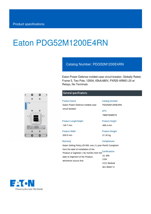
Eaton PDG52M1200E4RNEaton Power Defense molded case circuit breaker, Globally Rated, Frame 5, Two Pole, 1200A, 65kA/480V, PXR20 ARMS LSI w/ Relays, No TerminalsGeneral specificationsEaton Power Defense molded case circuit breakerPDG52M1200E4RN 786679286579139.7 mm 406.4 mm 209.5 mm 21.32 kg Eaton Selling Policy 25-000, one (1) year from the date of installation of theProduct or eighteen (18) months from thedate of shipment of the Product,whichever occurs first.RoHS Compliant UL 489CSACCC MarkedIEC 60947-2Product NameCatalog Number UPCProduct Length/Depth Product Height Product Width Product Weight WarrantyCompliancesCertifications1200 AComplete breaker 5Two-polePD5 Global Class A PXR 20 LSI w/ARMS600 Vac600 VNo Terminals65 kAIC at 480 Vac 100 kAIC Icu/ 100 kAIC Ics/ 220 kAIC Icm @240V (IEC) 15 kAIC Icu/ 7.5 kAIC Ics/ 31.5 kAIC Icm @690V (IEC) 65 kAIC @480/277V (UL) 100 kAIC @240V (UL)70 kAIC Icu/ 53 kAIC Ics/ 154 kAIC Icm @380-415V (IEC) 50 kAIC Icu/ 40 kAIC Ics/ 105 kAIC Icm @440V (IEC) 35 kAIC @600/347V (UL)30 kAIC Icu/ 25 kAIC Ics/ 63 kAIC Icm @525V South Africa (IEC)50 kAIC Icu/ 30 kAIC Ics/ 105 kAIC Icm @480V Brazil (IEC)1200 AEaton Power Defense MCCB PDG52M1200E4RN 3D drawing Power Xpert Protection Manager x64Amperage Rating Circuit breaker frame type Frame Number of poles Circuit breaker type Class Trip TypeVoltage rating Voltage rating - max Terminals Interrupt rating Interrupt rating rangeTrip rating 3D CAD drawing packageApplication notesConsulting application guide - molded case circuit breakersPower Xpert Protection Manager x32BrochuresStrandAble terminals product aidPower Defense brochurePower Defense molded case circuit breaker selection posterPower Defense technical selling bookletCatalogsPower Defense molded case circuit breakers - Frame 5 product aid Power Xpert Release trip units for Power Defense molded case circuit breakersMolded case circuit breakers catalogCertification reportsPDG6 CSA certificationPDG5 CB reportPDG5 CCC certificationPDG5 CSA CertificationPDG6 CCC certificatePower Defense Declaration concerning California’s Proposition 65EU Declaration of Conformity - Power Defense molded case circuit breakersPDG5 UL authorizationInstallation instructionsPower Defense Frame 2/3/4/5/6 voltage neutral sensor module wiring instructions – IL012316ENPower Defense Frame 4_5 flex shaft handle mech assembly instructions - IL012284ENPower Defense Frame 5 aux, alarm, shunt trip and uvr instructions(IL012201EN).pdfPower Defense Frame 5 vertical padlockable handle lock hasp installation instructions - IL012283ENPower Defense Frame 5 key interlock installation instructions -IL012294ENPower Defense Frame 5 walking beam installation instructions -IL012290ENPower Defense Frame 5 breaker status module installation instructions – IL012307ENPower Defense Frame 4_5_6 high performance flex shaft handle mech assembly instructions - IL012296ENInstallation videosPower Defense Frame 5 Trip Unit Replacement Animated Instructions Power Defense Frame 5 UVR Trip How-To VideoPower Defense Frame 5 Aux, Alarm, ST and UVR Animated Instructions.rh1Power Defense Frame 5 Shunt Trip, Aux and Alarm Trip How-To Video Power Defense Frame 5 Trip Unit Upgrade Relays Board, Animated Instructions.rhPower Defense Frame 5 Trip Unit Upgrade Wire Harnesses, Animated Instructions.rhMultimediaPower Defense molded case circuit breakersPower Defense Frame 2 Variable Depth Rotary Handle Mechanism Installation How-To VideoPower Defense Frame 5 Trip Unit How-To VideoEaton Power Defense for superior arc flash safetyPower Defense Frame 6 Trip Unit How-To VideoPower Defense Frame 3 Variable Depth Rotary Handle Mechanism Installation How-To VideoPower Defense BreakersSpecifications and datasheetsEaton Specification Sheet - PDG52M1200E4RNTime/current curvesPower Defense time current curve Frame 5 - PD5White papersMolded case and low-voltage power circuit breaker healthIntelligent power starts with accurate, actionable dataSingle and double break MCCB performance revisited Implementation of arc flash mitigating solutions at industrial manufacturing facilitiesIntelligent circuit protection yields space savingsMaking a better machineSafer by design: arc energy reduction techniquesMolded case and low-voltage breaker healthEaton Corporation plc Eaton House30 Pembroke Road Dublin 4, Ireland © 2023 Eaton. All Rights Reserved. Eaton is a registered trademark.All other trademarks areproperty of their respectiveowners./socialmedia。
常用共模电感外型图
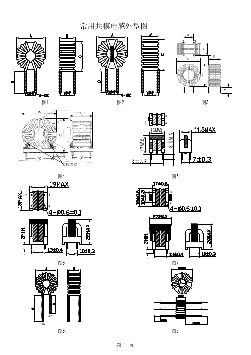
*CMI350uH/1A/H9 1.0350321768VDC 12645图1、2*CMI500uH/1A/H10 1.0500391768VDC 13 6.545图1、2*CMI2.0mH/1A/H14 1.020********VDC 17968图1、2CMI1.5mH/1A/H14 1.01500791768VDC 17968图1、2CMI1.0mH/1A/H14 1.010********VDC 17968图1、2CMI2.0mH/1.5A/H14 1.52000501768VDC 17968图1、2CMI1.5mH/1.5A/H14 1.51500441768VDC 17968图1、2CMI1.0mH/1.5A/H14 1.51000371768VDC 17968图1、2*CMI1.5mH/2A/H14 2.01500441768VDC 17968图1、2CMI1.0mH/2A/H14 2.010********VDC 17968图1、2CMI500uH/3A/H14 3.0500151768VDC 18968图1、2CMI350uH/3A/H14 3.0350131768VDC 18968图1、2CMI240uH/3A/H14 3.024*******VDC 18968图1、2CMI170uH/4A/H14 4.017071768VDC 18968图1、2CMI170uH/5A/H14 5.017061768VDC 19968图1、2CMI6.0mH/1A/H1608 1.060001571768VDC 1912711图1、2CMI4.2mH/1A/H1608 1.042001301768VDC 1912711图1、2CMI3.0mH/1A/H1608 1.030001131768VDC 1912711图1、2CMI4.2mH/1.5A/H1608 1.54200731768VDC 2013711图1、2CMI3.0mH/1.5A/H1608 1.53000641768VDC 2013711图1、2CMI3.0mH/2A/H160808 2.03000541768VDC 1912711图1、2CMI2.0mH/2A/H1608 2.020********VDC 1912711图1、2*CMI1.5mH/3A/H1608 3.01500251768VDC 2013712图1、2CMI1.0mH/3A/H1608 3.010********VDC 2013712图1、2CMI700uH/3A/H1608 3.0700191768VDC 2013712图1、2CMI500uH/4A/H1608 4.0500121768VDC 2013712图1、2CMI350uH/4A/H1608 4.0350101768VDC 2013712图1、2CMI350uH/5A/H1608 5.035091768VDC 2013712图1、2CMI240uH/6A/H1608 6.025061768VDC 2014712图1、2CMI170uH/7A/H16087.017051768VDC 2014712图1、2CMI3.0mH/1A/H1605 1.030001161768VDC 198.578图1、2CMI2.0mH/1A/H1605 1.020********VDC 198.578图1、2CMI3.0mH/1.5A/H1605 1.53000651768VDC 198.578图1、2CMI1.5mH/2A/H1605 2.01500391768VDC 198.578图1、2CMI1.0mH/2A/H1605 2.010********VDC 198.578图1、2CMI700uH/2A/H1605 2.0700281768VDC 198.578图1、2CMI1.0mH/3A/H1605 3.010********VDC 20978图1、2CMI700uH/3A/H1605 3.0700181768VDC 20978图1、2CMI350uH/4A/H1605 4.0350111768VDC 20978图1、2CMI240uH/5A/H1605 5.025071768VDC 201078图1、2CMI3.0mH/2A/H18 2.03000611768VDC 21978.5图1、2CMI2.0mH/2A/H18 2.020********VDC 21978.5图1、2CMI1.5mH/2A/H18 2.01500431768VDC 21978.5图1、2*CMI2.0mH/3A/H18 3.020********VDC 221078.5图1、2CMI1.5mH/3A/H18 3.01500291768VDC 221078.5图1、2*CMI700uH/4A/H18 4.0700151768VDC 2210.578.5图1、2CMI500uH/4A/H184.0500131768VDC221078.5图1、2MAX MAX 参考参考MAX 1mA,5s @1kHz,0.3V 流(A)流(A)MAX MAX参考参考@1kHz,0.3VMAX1mA,5sCMI500uH/5A/H18 5.0500111768VDC231178.5图1、2 CMI350uH/5A/H18 5.035091768VDC231178.5图1、2 CMI350uH/6A/H18 6.035071768VDC231178.5图1、2 CMI7.0mH/2A/H22H 2.07000992000VAC2916912图3 CMI6.0mH/2A/H22H 2.06000912000VAC2916912图3 CMI4.2mH/2A/H22H 2.04200782000VAC2815912图3 CMI6.0mH/3A/H22H 3.06000602000VAC2916912图3 *CMI4.2mH/3A/H22H 3.04200502000VAC2814912图3 CMI3.0mH/3A/H22H 3.03000432000VAC2814912图3 CMI1.5mH/4A/H22H 4.01500242000VAC2914912图3 CMI1.0mH/4A/H22H 4.010********VAC2914912图3 *CMI1.0mH/5A/H22H 5.010********VAC2813912图3 CMI700uH/5A/H22H 5.0700142000VAC2914912图3 CMI700uH/6A/H22H 6.0700112000VAC3014912图3 CMI500uH/7A/H22H7.050082000VAC3014912图3 CMI1.0mH/8A/H22H8.010********VAC3014912图3 CMI700uH/8A/H22H8.070062000VAC3014912图3 CMI20mH/3AY/H25 3.0200001212000VAC322217.515图4 CMI15mH/3AY/H25 3.0150001052000VAC322217.515图4 CMI10mH/3AY/H25 3.010*********VAC322217.515图4 CMI7.0mH/3AY/H25 3.07000722000VAC322217.515图4 CMI10mH/4AY/H25 4.010*********VAC322217.515图4 CMI7.0mH/4AY/H25 4.07000572000VAC322217.515图4 CMI6.0mH/4AY/H25 4.06000522000VAC322217.515图4 CMI4.2mH/4AY/H25 4.04200442000VAC322217.515图4 CMI3.0mH/4AY/H25 4.03000382000VAC322217.515图4 CMI2.0mH/4AY/H25 4.020********VAC322217.515图4 *CMI3.0mH/5AY/H25 5.03000312000VAC322217.515图4 CMI2.0mH/5AY/H25 5.020********VAC332217.515图4 CMI1.5mH/5AY/H25 5.01500222000VAC332217.515图4 CMI2.0mH/6AY/H25 6.020********VAC332217.515图4 CMI1.5mH/6AY/H25 6.01500182000VAC332217.515图4 CMI1.0mH/6AY/H25 6.010********VAC332217.515图4 CMI2.0mH/7AY/H257.020********VAC342317.515图4 CMI1.5mH/7AY/H257.01500162000VAC342317.515图4 CMI1.0mH/7AY/H257.010********VAC342317.515图4 CMI1.5mH/8AY/H258.01500132000VAC342317.515图4 *CMI1.0mH/10AY/H2510.010*******VAC342317.515图4 CMI700uH/10AY/H2510.070072000VAC342317.515图4 *CMI30uH/1A/H8* 1.02027500VDC10433图8 *CMI16mH/1A/W14** 1.0160001742000VAC181068图1、2 *3CMI2.0mH/8A/H318.020********VAC3820---CMI15mH/0.2A/U9.80.21500023302000VAC----图5 CMI10mH/0.2A/U9.80.21000018922000VAC----图5 CMI6.0mH/0.3A/U9.80.360009032000VAC----图5 CMI4.2mH/0.3A/U9.80.342007572000VAC----图5 CMI3.0mH/0.3A/U9.80.330006472000VAC----图5流(A)MAX1mA,5sMAX MAX参考参考@1kHz,0.3VCMI2.0mH/0.3A/U9.80.320005252000VAC----图5 CMI1.5mH/0.3A/U9.80.315004642000VAC----图5 CMI1.0mH/0.3A/U9.80.310003792000VAC----图5 *CMI2.0mH/0.5A/U9.80.520003092000VAC----图5 CMI1.5mH/0.5A/U9.80.515002732000VAC----图5 CMI1.0mH/0.5A/U9.80.510002232000VAC----图5 *CMI500uH/1A/U9.8 1.0500702000VAC----图5 CMI35mH/0.3A/U100.33500021042000VAC----图6 CMI28mH/0.3A/U100.32800018862000VAC----图6 CMI20mH/0.3A/U100.32000015892000VAC----图6 CMI15mH/0.3A/U100.31400013402000VAC----图6 CMI10mH/0.3A/U100.31000011212000VAC----图6 *CMI15mH/0.5A/U100.5140007872000VAC----图6 CMI10mH/0.5A/U100.5100006592000VAC----图6 CMI7.0mH/0.5A/U100.570005582000VAC----图6 *CMI3.0mH/1A/U10 1.030001622000VAC----图6 CMI2.0mH/1A/U10 1.020*********VAC----图6 CMI1.5mH/1A/U10 1.015001182000VAC----图6 CMI1.0mH/2A/U10 2.010********VAC----图6 *CMI4.2mH/2A/U16 2.04200922000VAC----图7 CMI3.0mH/2A/U16 2.03000782000VAC----图7 CMI2.0mH/2A/U16 2.020********VAC----图7 CMI1.5mH/2A/U16 2.01500552000VAC----图7 CMI1.0mH/2A/U16 2.010********VAC----图7 *CMI1.5mH/3A/U16 3.01500312000VAC----图7 CMI1.0mH/3A/U16 3.010********VAC----图7 CMI1.0mH/4A/U16 4.010********VAC----图7说明:此系列器件电流密度取值为6A/mm2,型号后面带*的为镍锌磁芯绕制,带**的为非晶磁芯绕制。
- 1、下载文档前请自行甄别文档内容的完整性,平台不提供额外的编辑、内容补充、找答案等附加服务。
- 2、"仅部分预览"的文档,不可在线预览部分如存在完整性等问题,可反馈申请退款(可完整预览的文档不适用该条件!)。
- 3、如文档侵犯您的权益,请联系客服反馈,我们会尽快为您处理(人工客服工作时间:9:00-18:30)。
序号 NO
边墙胶带 MARGIN TAPE
上下 TOP PIN
线材 WIRE
N1
/
/ 0.40TEX-E
N2
/
/ 2UEW0.40
圈数 TURNS
13TS 13TS
设计料号/DESING P/N:YHT1206041106-01 页次/PAGE:4/4
端子/PIN
入
出
IN
OUT
1
2
4
3
绝缘 胶带 TAPE
CUSTOMER : 均和科技
承
认
DATE:
书
2012. 11. 15
SPECIFICATION FOR APPROVAL
PRODUCT NAME: YOUR PART NO.: OUR PART NO.:
磁环电感
MTC100604-105T 立式
RECEPTION THE SPECIFICATION HAS BEEN ACCEPTED.
UL 编号 UL NO
130℃ 130℃
SHENZHEN CITY CHENGWEI INDUSTRY CO LTD E227475 HOI LUEN ELECTRICAL MANUFACTURER COE1L6T4D409
SHENZHEN CITY CHENGWEI INDUSTRY CO LTD
1KHz/0.25V
耐压/HI-POT TEST
5mA/3S
测试仪器:CS2670A
测试脚位/PIN 测试标准/Standard
L2-1=3-4
12MH MIN
COIL-COIL
AC0.5KV
绝缘阻抗/ INSULATION RESISTANCE
5.材料清单/MATERIAL lIST:
Байду номын сангаас
序号 NU 1
E227474
HOI LUEN ELECTRICAL MANUFACTURER E1264408
E-mail:sales@ Tel:0755-33693505~6/33693526 Fax:
0755-61624574
3
0755-61624574
2
SHENZHEN MOTTO TECHNOLOGY Co., Ltd
深圳市迈翔科技有限公司 SHENZHEN MOTTO TECHNOLGY CO.,LTD
客户料号/CUSTOMER`S P/N:
产品规格/PRODUCT SPEC:T10*6*4
3.绕线明细表/WINDING:
名称 ITEM 磁芯 Core
材质规格 MATERIAL T10*6*5 R10K
2
漆包线 Wire
2UEW 94V-0
漆包线
3
Wire
TEX-E
三层绝缘线
DC500V DC500V
COIL-COIL COIL-CORE
>100MΩ
温度 ℃
130℃
供应商 SUPPLIER
(JINYUAN)(GUANGDA)(WUHUAN)
HONGKONG PRC:
MOTTO OPTOELECTRONICS CO., LIMITED
FLAT/RM B 8/F CHONG MING BUILDING 72 CHEUNG SHA WAN RD KOULOON HONGKONG
TEL:00852-23192933 FAX:00852-23195168
DSGD.
詹海伟
SHENZHEN MOTTO TECHNOLOGY Co., Ltd
深圳市迈翔科技有限公司 SHENZHEN MOTTO TECHNOLGY CO.,LTD
客户料号/CUSTOMER`S P/N:
设计料号/DESING P/N:YHT1006051106-01
产品规格/PRODUCT SPEC:T10*6*4
/ /
套管/TUBE
入
出
IN
OUT
/
/
/
/
备注 REMARK
三层绝缘线
备注/NOTE:
4.电气性能/ELECTRICAL CHARACTERISTICS:
测试项目/TEST ITEM
测试条件/TEST CONDITION
电感量/INDUCTANCE 测试仪器:GKT-1061
电感量平衡/INDUCTANCE BALANCE 测试仪器:GKT-1061
COMPANY:
CFMD
CHKD
DATE: RCVD
TOTAL: 8 PAGES
MANUFACTURING NAME:
深圳市迈翔科技有限公司
SHENZHEN MOTTO TECHNOLOGY Co., Ltd 3F, 9# Liangong Road, SanLian Industrial Zone, Longhua Town
CFMD.
CHKD.
Baoan district Shenzhen
TEL: +86 0755-33693505 33693506 33693526 Fax: +86 0755- 61624574
张 芬 朱友谊
E-mail: sales@
页次/PAGE:3/4
1.外观尺寸/CONFIGURATION DIMENSIONS(单位/UNIT:mm):
A 12 MAX
B
8MAX
C φ0.40±0.1
D 4.0±0.5
E 12 MAX
备注: 2.电原理图/CIRCUIT DIAGRAM:
E-mail:sales@ Tel:0755-33693505~6/33693526 Fax: