DAS2空调双机切换器说明
WIFI型空调双机切换智能控制器(机房环境监控)
WIFI型空调双机切换智能控制器FDY-H2012QHNW使用说明书V2.5非常感谢您使用我公司的产品,我公司专注遥控空调的全自动控制的开发与生产,实现空调的停电来电自启动,温度、定时、人体感应、切换、开关量输入、RS485输入、开关量输出等控制。
可根据客户要求定制功能,OEM,ODM。
欢迎来电咨询WIFI型空调双机切换智能控制器采用智能化设计,可以在一瞬间学习每一种空调红外遥控器的控制代码,使用和安装都非常灵活,简单。
广泛用于有两台空调的场合,实现两台空调的定时和温度切换。
在WIFI环境下,通过APP可以了解空调运行情况和环境温度状态和手动开关空调。
同时可以选配断电模块,烟感,漏水,红外探测器,温湿度,声光报警器等实现物理环境的监控。
报警方式除APP推送以外,还可以选择短信通知或电话通知。
用户无需配手机卡或者固话,现场有WIFI的情况下就可以轻松使用。
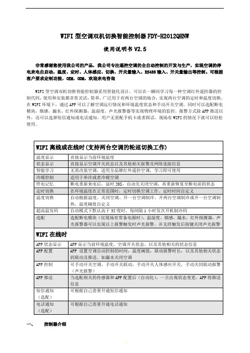
一、控制器介绍Power On Wait20技术参数:主机尺寸:130*110*25mm 外壳:铝合金 颜色:紫色工作电压:DC12V 工作温度:1~35度 (可应客户要求修改) WIFI 频率:2.4GHz控制器信号发射线 12V 电源空调双机切换控制器由一个控制器、两根信号发射线、一个12V (IC 方案)电源适配器组成。
控制器正面有LCD 液晶屏一个,右下脚有三个按键,分别标有“菜单”、“设置”和“确认”字样。
LCD 液晶屏用作显示环境温度,空调工作状态及管理人员设定修改参数时显示各进程及参数。
二、 安装说明1. 信号发射线与控制器连接控制器里的前三个接线口依次为空调A ,公共端,空调B ,将主信号线接线端子插入控制器相应的插口。
2. 信号发射线与空调的连接将信号发射线(发射端)用胶贴固定到空调自身红外遥控接收的区域即使用空调遥控器时红外发射头正对的位置或者打开空调接收面板置于接收头附近,。
3. 电源连接将电源适配器12V 与控制器连接,接上电源(与空调共一路电)。
什么是空调切换器
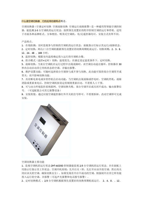
什么是空调切换器,它的应用功能特点概述。
空调切换器(空调定时切换空调故障切换空调运行故障报警)是一种通用型智能空调控制器,能监测2-3台空调机的运行状态,按照预先设置好的程序控制空调的运行和停机。
适用于市面各种品牌柜式、分体壁挂、吸顶式空调机,有/无遥控器均可,安装方式有所不同。
产品特点。
1、在线检测:实时监视参与控制的空调机的运行状态,面板指示灯标示其运行/故障状态。
2、定时切换:两台/三台空调机根据预先设置好的切换周期轮流运行,切换周期:2、3、8、12、24、48 、168小时;3、温控切换:根据室内温度确定投入运行的空调机台数。
4、组合模式(温控+定时)切换:温度优先,在满足设定温度条件下,定时切换。
5、故障切换:当某台空调机在运行过程中出现故障时,该空调自动退出循环,控制器在30秒内自动启动其它待机状态的空调,并输出报警。
6、维护设置功能:可随时选择某台空调参与或不参与切换,此功能可保持某台空调常开或常关,而不影响切换功能。
7、具有断电来电或异常停机自启动功能:当空调机出现故障或停电时,空调机停机;故障消除或重新来电后,控制空调机按设定的规则重新启动,不需要人工干预。
8、可与动力环境监控系统联网,空调切换失败,某台空调开启或关闭不成功,输出报警信号。
(可选配我公司其它报警设备)9、安装简便:通过识别空调遥控器红外开关机信号即可。
不需要拆卸、改动空调即可完成安装。
空调切换器主要功能1、监视空调机的运行状态:ZHT-ACO3D控制器能监视2/3台空调机的运行状态,并在面板上用指示灯指示其工作状态。
空调开机原则:先开后关(即,先打开应该开的空调,然后再关闭应该关的空调,确保切换安全),如果发现有开启不成功的空调,则强制开启其它所有能投入运行的空调,并报警(可选声光报警和电话拨号报警)。
2、定时切换模式:2/3台空调机根据预先设置好的切换周期轮流运行。
2、4、8。
、12、24、48、168小时三台的定时切换逻辑:默认开启2台,每台按设定的时间轮流休息。
LG 2室空调机器人用户指南说明书

TYPE : WINDOWP/NO : MFL67740303Please read this manual carefully before operating your set and retain it for future reference.ENGLISHSafety PrecautionsENGLISHOwner’s Manual 3Safety PrecautionsDo not allow water to runinto electric parts.•It will cause failure of machineor electric shock.conditioner may deteriorate,change color, or developVentilate the room well whenusing this appliancetogether with a stove, etc.•An oxygen shortage mayTurn off the power andbreaker firstly whencleansing the unit.•Since the fan rotates at highTurn off the main powerswitch when not using it fora long time.•Prevent accidental startup andIf strange sounds, or small orsmoke comes from product.Turn the breaker off ordisconnect the power supplycable.•There is risk of electricshock or fire.Do not open the suction inletgrill of the product duringoperation.•Otherwise, it may electricalshock and failure.If water enters the product, turnoff the power switch of the mainbody of appliance. Contactservice center after taking thepower-plug out from the socket.installation may cause fireor electric shockelectrical shock.ENGLISHSafety PrecautionsENGLISHOwner’s Manual 5Safety PrecautionsBe cautious not to touch thesharp edges wheninstalling.•It may cause injury.Avoid excessive cooling andperform ventilationsometimes.•Otherwise, it may do harm toyour health.Do not insert the hands orbars through the air inlet oroutlet during operation.•Otherwise, it may causepersonal injury.•It may cause injury.•It may cause product failure.•The appearance of the airconditioner may deteriorate,change color, or developsurface flaws.Do not step on theindoor/outdoor unit and donot put anything on it.•It may cause an injurythrough dropping of the unitor falling down.Always insert the filtersecurely.Clean it every two weeks.•Operation without filters willcause failure.Do not drink water drainedfrom air conditioner.•It contains containments andwill make you sick.6Room Air ConditionerBefore to OperationENGLISHOwner’s Manual 7IntroductionThis symbol alerts you to the risk of electric shock.This symbol alerts you to hazards that could cause harm tothe air conditioner.This symbol indicates special notes.This appliance should be installed in accordance with the National Electric Code.IntroductionVertical Air Deflector0DQXDO 7\SH0LFRP 7\SH8Room Air ConditionerInstallationENGLISHOwner’s Manual 910Room Air ConditionerStep 1Remove the air conditioner from its packaging and slide the air conditioner out of it ’s housing.Step 2Prepare the hole in the wall so that the bottom of the housing is well supported, the top has minimumcleara n ce and the air inlet louvers have clearance as shown. Holes from the outside through to the cavity should be sealed. The housing should slope down towards the rear by about 5mm to allow water formed during operation to drain.Step 3Install the housing into the wall and secure. Ensure the foam seals are not damaged. Flash, seal or fill gaps around the inside and outside to provide satisfactory appearance and protection against the weather, insects and rodents.Installation1.Slide the unit into the housing until it is firmly against the rear of the housing. Care is required to ensure the foam sealing strips on the housing remain in position.2.Connect the air conditioner to the power and coil excess cord length beneath the air conditioner base or control box.3.Engage the Chassis Lock into the bottom housing rail and secure to the base with the screwprovided.4.Remove the front panel from i t s carton and plastic bag and fit as per the Operating Instruction.5.Switch unit on. Check for operation of the unit and check for vibration in the installation.6.Fit the drain chute to the housing and run a drain line to a suitable location if required.Preferred method of installation into a timber framed wall, partition or window.UNIT MAY BE SUPPORTED BY A SOLID FRAME FROM BELOW OR BY A HANGER FROM A Alternative method of installation if externalsupport cannot be provided.45° BRICK CUT AWAY 45° BRICK CUT AWAY AIR OUTOPTION BInstallationscrew-driver tip (b).4.Then, rotate the inlet grille 180 degrees and insert the hooks into bottom holes of the front grille.5.Insert the filter and attach the front grille to the cabinet.B. If you want to pull out the filter downward;The grille is already designed that way.ENGLISHInstallationENGLISHOperating InstructionsOperating Instructions The controls will look like one of the following.Operating Instructionss COOLING DESCRIPTIONSFor Normal Cooling - Select High Cool or Med Cool with the Operation knob at the midpoint ofThermostat knob.For Maximum Cooling - Select High Cool with the Operation knob at the highest number available onyour Thermostat knob.For Quieter & Nighttime Cooling - Select Low Cool with the Operation knob at the midpoint ofThermostat knob.s AUTO SWING (available in some models), SI ) : Air swing is operated while OPERATION knob is set to the COOL position.OFF(, NO ) : Stops the operation of air swing.•When the air conditioner has been performed its cooling operation and is turned off or set to the fan position, wait at least 3 minutes before resetting to the cooling operation again.Operating InstructionsENGLISHOperating Instructions1.Push out the cover on the back of the remote control with your thumb2.Pay attention to polarity and insert two new AAA 1.5V batteries.3.Reattach the cover.In case the power comes on again after a power failure, Auto Restarting Operation is the function to operate procedures automatically to the previous operating conditions.Do not use rechargeable batteries. Make sure that both batteries are new. •if the air conditioner is not going to be used for an extended period of time Keep the remote control away from extremely hot or humid places.To maintain optimal operation of the remote control, the remote sensor should not be exposed to direct sunlight.•The remote control can be mounted on a wall using the mountable holder.Operating InstructionsENGLISHpart .Air DirectionOperating InstructionsThere are two drain holes at the product. (Fig. 1)One is at the rear and the other is at the bottom of the air conditioner unit.In case of cooling only model , there are two drain hole caps at the drain holes, but heat-pump model case, there is one drain hole cap at the rear. Additional drain hole cap is provided for heat pump model and drain pipe and washer are provided at the accessory.Select a drain method according to the following by each model.•Cooling only model1.Connecting drain from rear1)Remove the drain hole cap from rear at the product.2)After assembling washer and drain pipe, secure the drain pipe to the rear hole of the base pan. (Fig. 2) Press the drain pipe into the hole by pushing.3)Connect a drain hose of 9/16 inside diameter to the drain pipe as shown Fig. 32.Connecting drain from bottom1)Remove the drain hole cap from bottom at the product.2)After assembling washer and drain pipe, secure the drain pipe to the bottom hole of the base pan. (Fig. 4) Press the drain pipe into the hole by pushing.3)Connect a drain hose of 9/16 inside diameter to the drain pipe as shown Fig. 5Fig. 2Fig. 1Drain hole aFig. 4Fig. 5Fig. 3WASHER DRAIN HOLE CAPDRAIN PIPEWASHERDRAIN PIPEWASHERDRAIN PIPEOperating Instructions•Heat pump model1.Operating cooling mode1)As mentioned above, in case of heat pump model, there is no drain hole cap at thebottom,but for maximum cooling capacity,drain hole should be blocked by drain hole cap which is inside the accessory.2)For drain, please follow drain method same as cooling only model.2.Operating heating mode1)When it is operating heating mode, drain hole cap of bottom sideshould be removed.2)And please secure the drain pipe to the bottom hole of the basepan (Fig. 4) Press the drain pipe into the hole by pushing.3)Connect a drain hose of 9/16 inside diameter to thedrain pipe as shown Fig. 5ENGLISHMaintenance and ServiceENGLISHOwner’s Manual 21Maintenance and ServiceListed below are important instructions which will prevent malfunctions of the unit or serious problem with your air conditioner.1.Operate the unit from a stable power supply voltage variation must be within ±10 percent of therated voltage.2.DO NOT modify any part of the unit.3.DO NOT put sticks, rods, etc. into any part of the unit.4.DO NOT operate the unit without an air filter because dirt and lint will clog it and reduceperformance.5.DO NOT hold the power cord plug with wet hand.6.DO NOT obstruct the air inflow of the evaporator, it may cause some trouble.7.Turn the mode control to "O" or "OFF" and unplug your unit during the cool season or when youare checking the unit.8.Close the ventilation damper on windy days and/or during heavy rains.We strongly recommend that any servicing be performed by a qualified individual.22Room Air ConditionerMaintenance and ServiceA. WHEN AIR CONDITIONER DOESNOT OPERATE;1.Is the air conditioner plugged into the receptacle properly?2.Is the unit connected to a live receptacle supplying the proper voltage?3.Is the fuse blown or is the automatic circuit breaker off?4.Is there a local power failure?Try another electrical product.5.Has the air conditioner been accidentally switched off?6.Is the circuit overloaded by other devices on the same line?7.Is the thermostat knob set too low comparing to the temperature of indoor?8.If an extension cord is used, is the wire diameter large enough to carry the current?B. WHEN AIR CONDITIONER DOESNOT COOL AS IT SHOULD;1.Is the operation switch set properly?2.Is the thermostat control set properly to provide the desired cooling?3.Are there too many people than the usual number in the room?4.Is the air circulation restricted by drapes, furniture, etc., or by an improper vane setting?5.Are the doors or windows open, or is there an unusual heat source in the room?6.Is the ventilation damper closed for maximum cooling?7.Is the air filter clean so that it will not obstruct the air flow?8.Have all the steps outlined in the Installation Instructions been followed?9.Is the evaporator frosted? Frosting of the evaporator may occur during the spring and autumn months if there is a considerable temperature drop or during cool weather. If so, turn the operation switch to “MED FAN”. The fast air circulation will quickly defrost the coil so that normal cooling operating may be resumed.When you find something wrong with your room air conditioner, please check carefully referringto the following items. If you can’t find out the causes of trouble, get into contact with your dealer.Owner’s Manual 23Maintenance and Service Details of LG serial No.123456789101112*→*→*→H. G. IBRAHIM SHAKER COMPANY, LTD. SERVICE CENTER JEDDAH RIYADH AL-KHOBARP. O. BOX 200, JEDDAH 21411 KINGDOM OF SAUDI ARABIA P. O. BOX 15, RIYADH 11411 KINGDOM OF SAUDI ARABIA P. O. BOX 78, AL-KHOBAR 31952 KINGDOM OF SAUDI ARABIA CUSTOMER SERVICE CALL CENTER Toll Free No. 8002445454Service Centre No. 92000605424 Room Air ConditionerMaintenance and ServiceENGLISH Owner’s Manual 2526Room Air Conditioner。
大金空调监控协议转换器

大金空调监控协议转换器专利说明书发明人穆丹枫技术领域本实用新型提供了一种通用的RS485接口,支持MODBUS-RTU协议,可以方便的实现在大金空调的远程监控和两台空调之间实现轮流工作,适用于实现以下功能:1 通过MODBUS协议读取大金空调的运行状态,实现远程控制。
2 机房空调的时间轮值(双机切换)。
3 读取大金空调的故障状况,实现故障报警背景技术日本大金空调采用高效耐用的优质压缩机和稳定易控的电路系统,十分适合机房使用,大金空调提供了P端子应用于外接监控系统,可以多台空调联网运行,统一调度。
机房空调运行条件苛刻,24小时运转使压缩机温度会不断攀升,遇到外机过脏或电压偏低等情况都会造成系统故障,为解决此问题,让两台空调轮流工作是合适的解决办法,一方面大大降低了故障几率,另一方面,在一台机出现故障的情况下可及时转换到另一台运行,特别适应于无人值守的情况。
因大金空调采用日本独有的数据通信传输协议Homebus,和国内常见的RS485传输协议并不兼容,限制了大金空调在远程监控和智能控制方面的应用。
为解决此问题,我设计这款智能控制器,利用两条无极性的数据线从大金空调P端子将空调运行数据采集,传输到主板进行数据转换和执行,转换后的协议采用RS485信号传输,供上位机进行二次开发和监控。
发明内容本实用新型所要解决的技术问题是,利用两条无极性的数据线从大金空调P 端子将空调运行数据采集,转换为RS485接口输出,转换后的通信协议为MODBUS-RTU.本实用新型是这样的,先利用HBS解码电路对空调发出的HBS信号进行解码,用单片机的程序对编码进行分析,然后将空调机的开关和温度代码写入存储器进行记忆;控制器外接485驱动电路,经CPU运算后,向外输出MODBUS协议格式的RS485信号。
本设备还配有热敏电阻,不停对环境温度进行判断,并显示在数码管上。
控制器有按纽输入设定温度和切换时间,当控制器工作时,中央控制器CPU对通信传输的信号进行综合判断,发出控制空调开关机等指令,系统也会把空调的运行状况和故障情况实时传递到485端口,供上位机查询。
D2MQ系列微型基本切换器说明书

D 2M QUltra Slim Snap-actionSwitch with 2.7 mm in depth●Excellent electrical characteristics and snap action mechanism in spite of its ultra small size. ●Ideal for applications where size is extremely limited and high reliability is demanded.RoHS CompliantModel Number Legendthe Switch is viewed from the direction of the arrow in the drawing below.Contact Form●SPDTContact SpecificationsD2MQ-1@@@ 3. Terminal s None : PCB termin a l s (S tr a ight) -TL : PCB Termin a l s (Left-a ngled) -TR : PCB Termin a l s (Right-a ngled)1. ActuatorNone : Pin pl u nger L : Le a f lever 2. S witchin g capacity None : 30 VDC 0.5A -105 : 30 VDC 50mA<Hinge lever>D2MQ-@@-1@ 3. Terminal s None : PCB termin a l s (S tr a ight) -L : PCB Termin a l s (Left-a ngled) -R : PCB Termin a l s (Right-a ngled)1. Actuator4L: Hinge lever 2. Ratin gsNone : 30 VDC 0.5A -105 : 30 VDC 50mA123123ItemModel0.5 A models50 mA modelsContactSpecification RivetMaterial Silver platedGold platedGap(standard value)0.15 mmMinimum applicable load (see note)5 VDC 50 mA5 VDC 5 mAD2MQ Subminiature Basic SwitchD 2 M Q RatingsNote.The above rating values apply under the following test conditions.(1) Ambient temperature: 20±2°C(2) Ambient humidity: 65±5%(3) Operating frequency: 30 operations/minCharacteristicsNote.The data given above are initial values.*1.For the pin plunger models, the above values apply for use at the freeposition and total travel position. For the lever models, they apply at thetotal travel position. Close or open circuit of the contact is 1ms max.*2.For testing conditions, consult your OMRON sales representative. Terminals/Appearances (Unit:mm)●PCB terminals (Straight) ●PCB terminals (Left-angled)●PCB terminals (Right-angled) <PCB Mounting Dimensions (Reference)>Mounting Holes (Unit: mm)Type0.5A models 50mA modelsRated voltage Item Resistive load30 VDC0.5A 50 mAPermissible operating speed0.1 mm to 0.5 mm/s (for pin plungermodels)PermissibleoperatingfrequencyMechanical 60operations/minElectrical 30 operations/minInsulation resistance100 MΩ min. (at 250 VDC with insulationtester)Contact resistance (initial value) 100 mΩ max.DielectricstrengthBetweenterminals of thesame polarity500 VAC 50/60 Hz 1minBetweencurrent-carryingmetal parts andground500 VAC 50/60 Hz 1minVibrationresistance * 1Malfunction 10 to 55 Hz, 1.5 mm double amplitudeShockresistanceDurability 1,000m/s2 {approx. 100G} max.Malfunction * 1300 m/s2 {approx. 30G} max.Durability * 2Mechanical 30,000 operations min. (60 operations/min)Electrical 10,000operationsmin.(30 operations/min)Degree of protection IEC IP40Ambient operating temperature−15°C to +70°C (at ambient humidity of60% max.)(with no icing or condensation)Ambient operating humidity 35% to 85% (for +5°C to +35°C)Weight Approx.0.3g 2-1.6+0.12-1.6+0.12-1.6+0.10a. hole s* Termin a l g a p i s 1 pitch2-1.6 di a. mo u nting hole sD2MQSubminiature Basic SwitchD2M QDimensions (Unit: mm) /Operating CharacteristicsThe illustrations and drawings are for PCB terminals (straight) models.Refer to "Terminals/Appearances" of the previous page for details on models with PCB terminals (Right-angled) and PCB terminals (Left-angled).Note 1.Unless otherwise specified, a tolerance of ±0.15 mm applies to all dimensions. Note 2.The operating characteristics are for operation in the A direction ().Precautions★Please refer to "Basic Switches Common Precautions" for correct use.●Soldering•Terminal connectionsWhen soldering terminals manually, perform soldering within 3 seconds at iron tip temperature no higher than 300°C. Do not apply any external force for 1 minute after soldering. When applying solder, keep the solder away from the case of the Switch and do not allow solder or flux to flow into the case. It is recommended that you apply flux guard to the mounting surface of the Switch.●MountingUse M1.4 mounting screw with plane washers or spring washers to securely mount the Switch. Tighten the screws to a torque of 0.08 to 0.1 N·m {0.8 to 1 kgf·cm}.●Operation•Do not apply a force more than two times the rated operating force to the actuator and leaf lever.•Provide an amount of OT that equals or exceeds the standard. •Do not change the operating position by modifying the actuator.•Do not use the Switch in an application where the operating speed is extremely slow or the actuator is set in the midpoint between the free position and operating position.•Mount the pin plunger so that the operating force is applied in perpendicular alignment with the stroke of the actuator. •Do not apply a shock to the actuator, otherwise, the Switch may be damaged.•Do not apply excessive force to the actuator of the Leaf Lever Switch in the operating, releasing, and horizontal directions.●Pin plunger Models Operating Force OF Max. Releasing ForceRF Min. 1.18N {120 gf} 0.20N {21 gf}Pretravel PT Max. Overtravel OT Min.Movement Differential MD Max. 0.4 mm 0.1 mm 0.1 mm Operating PositionOP5.7±0.2 mmD2MQ-1 D2MQ-1-TL D2MQ-1-TR D2MQ-1-105●Leaf lever Models Operating ForceOF Max. Releasing Force RF Min.0.59N {60 gf} 0.08N {8 gf}Pretravel PT Max. Overtravel OT Min.Movement Differential MD Max. 2.4 mm 0.3 mm 0.7 mm Free Position FP Max. Operating PositionOP9.6 mm 6.7±0.5 mm* Pl as tic leverD2MQ-1L D2MQ-1L-TL D2MQ-1L-TR D2MQ-1L-105* Pl as tic lever●Hinge lever Models Operating Force OF Max. Releasing ForceRF Min.0.39N {40 gf} 0.04N {4 gf}Pretravel PT Max. Overtravel OT Min.Movement Differential MD Max. 2.1 mm 0.3 mm 0.7 mm Free Position FP Max. Operating PositionOP8.7 mm 7.1±0.5 mmD2MQ-4L-1 D2MQ-4L-1-L D2MQ-4L-1-R D2MQ-4L-105-1 D2MQ-4L-105-1-L D2MQ-4L-105-1-RCautionsCorrect UseD2MQ Subminiature Basic SwitchD2MQ•Applic a tion ex a mple s provided in thi s doc u ment a re for reference only. In a ct ua l a pplic a tion s, confirm e qu ipment f u nction s a nd sa fety b efore us ing the prod u ct.• Con su lt yo u r OMRON repre s ent a tive b efore us ing the prod u ct u nder condition s which a re not de s cri b ed in the m a n ua l or a pplying the prod u ct to n u cle a r control s y s tem s, r a ilro a d s y s tem s, a vi a tion s y s tem s, vehicle s, com bus tion s y s tem s, medic a l e qu ipment, a m us ement m a chine s, sa fety e qu ipment, a nd other s y s tem s or e qu ipment th a t m a y h a ve a s erio us infl u ence on live s a nd property if us ed improperly. M a ke su re th a t the r a ting s a nd perform a nce ch a r a cteri s tic s of the prod u ct provide a m a rgin of sa fety for the s y s tem ore qu ipment, a nd b e su re to provide the s y s tem or e qu ipment with do ub le sa fety mech a ni s m s.Note: Do not u s e thi s document to operate the Unit.OMRON CorporationELECTRONIC AND MECHANICAL COMPONENT S COMPANY Contact: /ecb Cat. No. B034-E1-080812(0207)(O)。
Daikin 高压吸气机分离式空调产品说明书

0936Owner’s ManualTABLE OF CONTENTSPAGESAFETY PRECAUTIONS2 .....................................................................................GENERAL2 .................................................................................................INDOOR UNIT PART NAMES3 ................................................................................. REMOTE CONTROL PART NAMES4............................................................................DISPLAY PANELS5 .......................................................................................... REMOTE CONTROL6 ........................................................................................ REMOTE CONTROL FUNCTIONS7.............................................................................CLEANING,MAINTENANCE AND TROUBLESHOOTING9........................................................NOTE TO EQUIPMENT OWNER:Please read this Owner’s Information Manual carefully before installing and using this appliance and keep this manual for future reference.For your convenience,please record the model and serial numbers of your new equipment in the spaces provided.This information,along with the installation data and dealer contact information, will be helpful should your system require maintenance or service.UNIT INFORMATIONModel#___________________________________ Serial#___________________________________INSTALLATION INFORMATIONDate Installed_____________________________DEALERSHIP CONTACT INFORMATION Company Name:_________________________________ Address:_________________________________________ ________________________________________________ Phone Number:__________________________________ Technician Name:_________________________________ ________________________________________________SAFETY PRECAUTIONSAny time you see this symbol in manuals,instructions and on the unit,be aware of the potential for personal injury.There are three levels of precaution:DANGER identifies the most serious hazards which will result in severe personal injury or death.WARNING signifies hazards that could result in personal injury or death.CAUTION is used to identify unsafe practices which would result in minor personal injury or product and property damage. NOTE is used to highlight suggestions which will result in enhanced installation,reliability,or operation.GENERALThe high wall fan coil unit provides quiet,maximum comfort.In addition to cooling and/or heating,the high wall fan coil unit matched with an outdoor condensing unit will filter and dehumidify the air in the room to provide maximum comfort. IMPORTANT:The high wall fan coil unit should be installed by authorized personnel only;using approved tubing and accessories. If technical assistance,service or repair is needed,contact the installer.The high wall fan coil unit can be set up and operated from the remote control(provided).If the remote is misplaced,the system can be operated from the“Auto”setting on the unit. Operating Modes:The high wall fan coil unit has five operating modes.S Fan onlyS AutoS HeatingS CoolingS Dehumidification(DRY)Fan OnlyIn Fan Only mode,the system filters and circulates room air without changing room air temperature.AutoIn Auto mode,the system will automatically cool or heat the room according to the user-selected set point.HeatingIn Heating mode,the system heats and filters room air. CoolingIn Cooling mode,the system cools,dries and filters room air. Dehumidification(DRY)In Dehumidification mode,the system dries,filters and slightly cools room air e of this mode does not take the place of a dehumidifier.Remote ControlThe remote control transmits commands to set up and operate the system.The control has a window display panel that shows the current system status.The control can be secured to a surface when used with the mounting bracket provided.INDOOR UNIT PART NAMESFig.1-Indoor UnitFig.2-Remote ControllerDISPLAY PANELSNOTE:The display panel on the indoor unit can be turned on or off using the LIGHT button on the remote control.*The temperature readout will be replaced by an error code if there is a malfunction.heating temp.cooling power indicatorFig.3-Display PanelsREMOTE CONTROL PARTNAMESON/OFF button MODE button FAN button SWING button TURBO buttonTEMP button I FEEL button LIGHT button CLOCK button TIMER ON/TIMER OFF buttonSLEEP button 123456789101112Fig.4-Remote ControlRemote Control Display46.4 F heating function Fig.5-Remote Control DisplayREMOTE CONTROLNOTE:To switch between_C and_F,push the“MODE”and “▼”button simultaneously while the remote controller is off. IMPORTANT:The remote control can operate the unit from a distance of up to25ft.(7.6m)as long as there are no obstructions. This is one way communication only(from remote control to fan coil).The remote control can perform the following basic functions:S Turn the system ON and OFFS Select operating modeS Adjust room air temperature set point and fan speedS Adjust airflow directionBattery InstallationTwo AAA1.5v alkaline batteries(included)are required for operation of the remote control.To install or replace batteries:1.Slide the back cover off the control to open the batterycompartment.2.Remove old batteries if you are replacing the batteries.3.Insert batteries.Follow the polarity markings inside thebattery compartment.4.Replace battery compartmentcover.A08299 NOTE:1.When replacing batteries,do not use old batteries or a differenttype battery.This may cause the remote control to malfunction.2.If the remote is not going to be used for several weeks,removethe batteries.Otherwise battery leakage may damage the remote control.3.The average battery life under normal use is about6months.4.Replace the batteries when there is no audible beep from theindoor unit or if the Transmission Indicator fails to light.Remote Control Operation-Quick Start NOTE:When transmitting a command from the remote control to the unit,be sure to point the control toward the LED display on the front panel of the unit.The unit confirmsreceipt of a command by sounding an audible beep.1.Turn the unit on by pushing the ON/OFF button.2.Select the desired mode by pushing the mode button.Fig.6-Modes3.Select the temperature set point by pointing the controltoward the unit and pressing the“▲”or“▼”temperatureset point buttons until the desired temperature appears onscreen.4.Select the desired fan speed by pressing the FAN button toselect desired fan speed.5.Set the airflow direction.When the unit is turned on,thelouvers default to the cooling or heating position.The usercan adjust the default louver position by pushing the“SWING”buttons.For details on operating the SWINGlouvers,refer to the Remote Control Functions section.Emergency OperationIf the remote control is lost,damaged,or the batteries are exhausted, the ON/OFF button on the unit can be used to run the unit. Press the ON/OFF button once briefly when the system is off. To stop emergency operation,push the ON/OFF buttononce.WARNING:Use an insulated object to press the auto button.Fig.7-Emergency Operation REMOTE CONTROL FUNCTIONS The remote control is the interface between the user and the high-wall mands are entered by the user to control the system.Any command that has been entered with the remote control will remain in the memory until it is changed by the user or the batteries are replaced.NOTE:When entering commands,point the remote in the direction of the LED display on the front panel.appears for a short period of time on the remote control when the command is entered.The unit only emits an audible beep when the signals are received correctly.ON/OFF:Press this button to turn unit on and off.MODE:Each time this button is pressed,a mode is selected in a sequence that goes from AUTO,COOL,DRY,FAN and HEA T,as shownbelow:Fig.8-ModesAUTO:The AUTO mode is the default setting at start-up.In the AUTO mode,the set temperature will not appear on the LCD,and the unit automatically selects the suitable operation mode to provide comfort based on parameters set from the factory.COOL:To cool to the selected set point and remove moisture.System varies compressor speed to maintain desired temperature.DRY:Select the DRY MODE to increase moisture removal during warm humid conditions.The unit operates at low speed.The Fan Speed cannot be adjusted.Press the”SWING”button to adjust the fan blow angle.FAN:To circulate air without heating or cooling use the Fan Speed button to select speed from low to high.HEAT:To heat to the selected room set point.The system varies compressor speed to maintain desired room temperature.▼:Press this button once to decrease the setpoint by1_F.If the button is pressed for more than two seconds,the setpoint decreases rapidly in increments of1_F.In AUTO mode,set temperature is not adjustable.▲:Press this button to increase the setpoint by1_F.If the button is pressed for more than two seconds,the setpoint increases rapidly in increments of1_F.In AUTO mode,set temperature is not adjustable.FAN:Fig.9-FanspeedPress the Swing button to select different vertical(up and down) air discharge directions including Continuous Sweep.The Swing Louver icon appears.Press this button to set swing angle,which changesbelow.at current position)Fig.10-Swing buttonsTURBO:The desired room set point can be achieved faster in TURBO mode.After selecting the“HEAT”or“COOL”mode button, push the“TURBO”button.The TURBO icon appears on the remote controller and the unit runs at an ultra-high speed.To deactivate the feature,push the“TURBO”button again.The unit returns to normal operation.I FEEL:Press this button to use the I FEEL function,and the icon appears. The unit senses room temperature at the remote controller instead of at the indoor unit.It then adjusts airflow and temperature accordingly for the ultimate in personal comfort control and energy savings. Press the button again to exit this function.For best performance, keep remote controller away from heat or cold temperature sources while using this function.TEMP:By pressing this button,you can see the indoor set temperature, indoor ambient temperature or outdoor ambient temperature on the indoor unit’s display.The setting on remote controller is selected circularly as shown below:Fig.11-TempTimer ON-Timer OFFTo set when you want the unit to turn On at the end of a selected time period,use the button labeled“Time-ON”on the remote controller.Press this button to make the clock icon disappear, replaced with the word“ON”(blinking).Press“▲”or“▼”buttons to adjust timer setting1minute at a time.Press and hold “▲”or“▼”button to set timer more quickly.Press“Timer-ON”button again to confirm setting,and the word“ON”stops blinking. To cancel,press the“Timer OFF”.NOTE:Under Timer On and Off status,you can set T-ON and T-OFF simultaneously.Before setting timer,be sure toset clock to correct time.CLOCK SETTINGPress this button to set clock time.The Clock icon on remote controller blinks.Within5seconds,press“▲”or“▼”button to set clock time.With each press of the“▲”or“▼”buttons,the clock time increases or decreases by1minute.To quickly adjust the time setting,press and hold“▲”or“▼”button for2seconds. Release the button when you have reached the desired time setting. Press the“CLOCK”button to confirm the time,and clock icon stops blinking.NOTE:Clock time adopts24-hour mode.A12-hour format is not available.SLEEP:The unit automatically adjusts room temperature during your sleep time.This slight change in temperature will not affect your comfort level due to the natural effects that sleeping has on the body,however it saves on energy consumption and lowers your electric bill.The unit has four Sleep Modes to select from.Press the SLEEP button to select Sleep1,Sleep2,Sleep3,Sleep4modes or Cancel. The SLEEP icon appears.LIGHT:This function allows the user to turn the display ON or OFF on the front panel.Press the light icon to turn the indoor unit front panel ON or OFF.The remote control displays the Light Icon.WIFI Button:Press and hold this button for three seconds to turn WIFI function on or off.See the“Operation of Smart Control”section for more information.Only the set point temperature appears on the front panel and on the remote bination ButtonsCombination of“▲”and“▼”Buttons:Press“▲”and“▼”buttons simultaneously for8secondsor unlock the keypad.If the remoteis locked,is displayed.In this case,pressing any button,blinks three timesto acknowledge the keypad is locked.process to unlock the remote controller.Combination of“MODE”and“▼”Buttons: Switch between Fahrenheit and Centigrade.At unit OFF,press the “MODE’”and“-”buttons simultaneously to switch between_C and _F.Energy-Saving FunctionUnder the cooling mode,press the“TEMP”and“CLOCK”buttons simultaneously to start or stop the energy-saving function. When the energy-saving function starts”SE”displays on the remote controller,and the air conditioner adjusts the set temperature automatically according to the factory setting to reach the best energy-saving effect.Press the“TEMP”and“CLOCK”buttons simultaneously again to exit the energy-saving function. NOTE:S Under the Energy-Saving function,the fan speeddefaults to the auto speed and can not be adjusted.S Under the Energy-Saving function,the set temperature can not be adjusted.Press the“TURBO”button and theremote controller will not send the signal.S The Sleep and Energy-Saving functions can not operate at the same time.If the Energy-Saving function has beenset under the Cooling mode,press the Sleep button tocancel the Energy-Saving function,If the Sleep functionhas been set under the Cooling mode,start theEnergy-Saving function to cancel the Sleep function. 46_F Heating Functions:Under the heating mode,press the“TEMP”and“CLOCK”buttons simultaneously to start the46_F heating function.When this function starts,the“$”and46_F icons appear on the remote controller,and the air conditioner maintains the heating status. Press the“TEMP”and“CLOCK”buttons simultaneously again to exit the46_F heating function.NOTE:S Under the46_F heating function,the fan speed defaults to the auto speed and it can not be adjusted.S Under the46_F heating function,the set temperature can not be adjusted.Press the TURBO button and the remotecontroller will not send the signal.S The Sleep function and the46_F heating function can not operate at the same time.If the46_F heating functionhas been set under the Cooling mode,press the Sleepbutton to cancel the46_F heating function.If the Sleepfunction was set under the Cooling mode,the46_Fheating function cancels the Sleep function.CLEANING,MAINTENANCE AND TROUBLESHOOTINGPeriodic MaintenancePeriodic maintenance isrecommended to ensure proper operation of the unit.Recommended maintenance intervals may vary depending on the installation environment,e.g.,dusty zones,etc.Refer to Table 1.Cleaning the CoilClean the coil at the beginning of each cooling season,or when e a vacuum cleaner or a long-bristle brush to avoid damage to the coil fins.Air FiltersRemove and clean the air filters once a month.NOTE:If air filters show signs of excessive wear or are torn,they must be replaced.Contact your local dealer for replacement filters.1.Open front panel on unit.2.Pull filters down to remove.3.Vacuum filters.4.Clean with warm water.5.Shake filter to remove excess water and dry thoroughly.6.Replace filter by sliding into rack until filter snaps in place.7.Close front panel on unit.Indoor Unit Front PanelTo clean the front panel on the indoor unit,wipe the outside with a soft,dry cloth.If necessary,a mild liquid detergent can be applied and wiped off with a dry cloth.Preparing for Extended Shutdown PeriodClean the filters and reposition them in the unit.Operate the unit in Fan only mode for 12hours to dry all internal parts.Turn main power supply off and remove batteries from the remote control.System Operation RecommendationsThe items outlined in the following list helps to assure proper system operation:S Replace both remote control batteries at the same time.S Point the remote control toward the unit display panel when transmitting a command.S Keep doors and windows closed while unit is operating.S Contact an authorized service representative if a problem arises that cannot be easily resolved.S Do not perform cleaning or maintenance activities while unit is on.S Keep display panel on unit away from direct sunlight and heat as this may interfere with remote control transmissions.S Do not block air intakes and outlets on the indoor or outdoor units.Energy Saving RecommendationsThe following recommendations add greater efficiency to the ductfree system:S Select a comfortable thermostat setting and leave it at chosen setting.Avoid continually raising and lowering the setting.S Keep unit filter clean.Frequent cleaning may be necessary depending on indoor air quality.S Use drapes,curtains or shades to keep direct sunlight from heating room on very hot days.S Do not obstruct air intake on front panel.S Turn on air conditioning before indoor air becomes too uncomfortable.TroubleshootingRefer to Table 2before contacting your local dealer.Table1—Periodic MaintenanceINDOOR UNIT EVERY3MONTHS EVERY6MONTHS EVERY YEARClean Air Filter*Change Remote Control Batteries SSSOUTDOOR UNIT EVERY3MONTHS EVERY6MONTHS EVERY YEARClean Outdoor Coil from Outside Clean Outdoor Coil from Inside†Blow Air Over Electric Parts†Check Electric Connection Tightening†Clean Fan Wheel†Check Fan Tightening†Clean Drain Pans†SSSSSSS*Increase frequency in dusty zones.{Maintenance to be carried out by qualified service personnel.Refer to the Installation ManualTable2—TroubleshootingPROBLEM POSSIBLE CAUSE SOLUTIONIndoor unit emits a bad odor on start-up ∙Air filter dirty∙Output air still has odor after cleaning filter.∙Clean the air filter∙Contact your service representative.You hear water flowing noise when the unit is running ∙This is normal and is the refrigerant flowingthrough the system.∙No maintenance requiredIndoor unit produces a mist when the air conditioner is running ∙This is normal cooling and is caused by highhumidity and temperature in the room.∙No maintenance required.Mist should stop asroom is cooled down and the humidity is removed.Wireless remote control doesnot work∙Batteries are dead.∙Unit needs to be reset.∙See battery replacement section in this manual and replace batteries.∙Turn off power to indoor unit.Remove plug from wall and then reinsert plug.Restart unit.Water leaks into room from Indoor unit ∙Condensing water has overflowed∙Check indoor condensing drain or call yourrepresentative.Unit/System Does Not Work∙T o protect the unit upon an immediate restartafter a stop,the system controller delaysthe unit for3minutes before allowing the unitto start back up.∙The circuit breaker has tripped or a fusehas blown.∙Power failure.∙Error codes displayed∙Voltage is too low.∙After turning unit off,wait at least3minutes before trying to restart.∙Reset the circuit breaker or replace the fuse with the specified replacement fuse.∙Restart operation when the power is restored.∙Call your service representative.∙Call your service representative.Cooling is Not Working Properly ∙The filter is blocked with dust.∙T emperature is not set properly.∙A window or door is open.∙The outdoor unit is obstructed.∙The fan speed is too low.∙The operation mode is in Fan instead ofCool.∙Clean the air filter.∙Check the temperature and reset if necessary.∙Close the window or door.∙Remove the obstruction.∙Change the fan speed selection.∙Change the operating mode to Cool or reset theunit.Heating is Not Working Properly ∙The filter is blocked with dust.∙T emperature is set too low.∙A window or door is open.∙The outdoor unit is obstructed.∙Clean the air filter.∙Check the temperature and reset if necessary.∙Close the window or door.∙Remove the obstruction.Unit Stops During Operation∙The Off timer is not operating correctly.∙Error codes displayed ∙Restart the operating mode.∙Call your service representative.Copyright2015International Comfort Products Lewisburg,TN37091USAManufacturer reserves the right to change,at any time,specifications and designs without notice and without obligations.Catalog No:42102941000 Replaces:NEWEdition Date:06/15。
空调切换器使用说明
产品特点:
1、定时切换空调(6、8、12小时可选);
2、智能红外学习(能够学习空调的开、关机及遥控状态编码);
3、来电自启动(无需人为的操作和开启);
4、编码掉电不丢失,可保存100年;
5、用户操作、当前状态液晶显示(显示切换时间、运行状态、温度值);
6、空调启动故障自识别(一台启动失败,2分钟内自动启动另一台)。
分别对应主机上的三个绿色灯(灯1、2、3)。
(2)STU键:该键为编码学习键,可对空调的遥控编码进行学习。
“STU键”按键轮转图如下:
空调开机编码的学习:通过“STU键”切换到对应的界面,“S灯”(黄灯)长亮,表示已经进入学习状态,正等待“空调遥控器”发送开机信号,此时用“空调遥控器(遥控器目前是关机的状态)”对着主机,按空调遥控器的“开/关”键,主机将自动学习遥控器编码,当学习完成后,“S灯”自动熄灭,表示学习完成。
空调关机编码的学习:通过“STU键”切换到对应的界面,“S灯”(黄灯)闪烁,表示已经进入学习状态,正等待“空调遥控器”发送关机信号,此时用“空调遥控器(遥控器目前是开机的状态)”对着主机,按遥控器的“开/关”键,主机将自动学习遥控器编码,当学习完成后,“STU灯”自动熄灭,表示学习完成。
注意:空调1的编码学习必须是空调1的遥控器,空调2的编码学习必须是空调2的遥控器。
(3)液晶显示:
主界面显示:空调目前的状态、定时的时间、实时温度。
EQU-1表示空调1,EQU-2表示空调2(状态ON表示对应的空调开启,OFF表示对应的空调关闭);右上角的xxh表示:定时xx小时;xx’C表示摄氏温度值。
界面Study:表示进入学习状态,(ON表示空调开启学习,OFF表示空调关闭学习)其他提示同主界面。
Daikin 17 SEER 双阶段空调系统产品说明书
421411703026/02/17Specifications subject to change without notice.HIGH EFFICIENCY 17SEER TWO-STAGE AIR CONDITIONER WITH OBSERVER ®COMMUNICATING CONTROL SYSTEM2THRU 5TONS SPLIT SYSTEM 208/230Volt,1-phase,60Hz REFRIGERATION CIRCUITS Copeland Scroll ®Ultratech t compressors on all models S Filter-drier supplied with every unit for field installation S External high and low refrigerant service ports S High and low pressure switches S Copper tube /aluminum fin coilPERFORMANCES Self-configuring installation capabilities when used withObserver ®Wall ControlS Outdoor temperature sensor factory installed (for use with Observer Wall Control only)S Ball Bearing PSC fan motors on all modelsS High performance compressor sound shield standard S Isolation compressor grommetsEASY TO INSTALL AND SERVICES Text based diagnostics with Observer ®Wall ControlS Only 2control wires required from communicating indoor unitto condenserS Easy access service valves on all models S Innovative control box designS Only two screws to access control panel S Factory charged with R-410A refrigerantBUILT TO LASTS High gloss,baked-on powder coat finish over galvanized steel S Post-painted (black)coil finsS C oated,weather-resistant cabinet screwsS Coated inlet grille with 3/8”(10mm)spacing for extra protection S Corner posts for extra strength and styleWARRANTY*S 10year No Hassle Replacement t limited warrantyS 5year parts limited warranty (including compressor and coil)-With timely registration,an additional 5year parts limited warranty (including compressor andcoil)This product has been designed and manufactured to meet ENERGY ST AR criteria for energy efficiency when matched with appropriate coil components.However,proper refrigerant charge and proper air flow are critical to achieve rated capacity and efficiency.Installation of this product should follow the manufacturer’s refrigerant charging and air flow instructions.Failure to confirm proper charge and airflow may reduce energy efficiency and shorten equipmentlife.Use of the AHRI Certified TM Mark indicates a manufacturer’s participation in the program.For verification of certification for individual products,go to .*Applies to original purchaser/homeowner,some limitations may apply.See Warranty certificate for complete details.Model Number Size (tons)Nominal Btu/hr Min.Circuit Ampacity Max.Fuse or BreakerOperating Dimensionsheight x width x depth in.(mm)Ship /Operating Weight lbs.(kg)CCA724GKA 224,00014.52035-1/2x31-3/16x31-3/16(902x792x792)222/183(101/83)CCA736GKA 336,00019.83535-1/2x31-3/16x31-3/16(902x792x792)256/217(116/98)CCA748GKA 448,00027.84040-3/8x35x35(1026x889x889)326/283(148/128)CCA760GKB560,00037.36040-3/8x35x35(1026x889x889)327/284(148/129)CCA7SoftSound r SXT+Product SpecificationsTSTAT0201CW(Sold Separately)PRODUCT SPECIFICATIONS Split System Air Conditioner:CCA7242141170302Specifications subject to change without notice.OUTDOOR UNIT MODEL NUMBER IDENTIFICATION GUIDE (single phase)Digit Position:12345,6789101112Example Part Number:C C A 724G K A 200C =Comfortmaker MainlineBRANDING C =Communicating KEYCHARACTERISTICA =Air Conditioner H =Heat Pump TYPE6=16SEER 7=17SEER 8=18SEER 9=19SEERNOMINAL EFFICIENCY24=24,000BTUH =2tons 36=36,000BTUH =3tons 48=48,000BTUH =4tons 60=60,000BTUH =5tonsNOMINAL CAPACITYG =Coil Guard Grille FEATURESK =208/230-1-60VOLTAGESales CodeEngineering Revision Extra Digit Extra DigitACCESSORIES PART NUMBER IDENTIFICATION GUIDEDigit Position:123456,78,910,11Example Part Number:N A S A 00101C HN =Non-Branded A =AccessoryPRODUCT GROUPS =Split System (AC &HP)KIT USAGEA =OriginalB =2nd GenerationMAJOR SERIES0=Generic or Not Applicable 4=R-410AREFRIGERANTProduct Identifier Number Package QuantityType of Kit (Example:CH =Crankcase Heater)T Y .3. S E R I E S D E S I G N A T I O N I S T H E 10T H P O S I T I O N O F T H EU N I T M O D E L N U M B E U N I T S I Z EY "M I N I M U M R O O F -T O P M O U N T I N G M I N I M U M G R O U N D M O U N T I N G R .""X "PRODUCT SPECIFICATIONSSplit System Air Conditioner:CCA7421411703023Specifications subject to change without notice.PRODUCT SPECIFICATIONS Split System Air Conditioner:CCA7442141170302Specifications subject to change without notice.PHYSICAL DATAModel Size24364860Nominal Cooling Capacity (BTU/hr)24,00036,00048,00060,000Sound Rating**,High Stage (dBA)Low Stage (dBA)7271717072707272PSC Fan Motor HP1/121/101/41/4Fan RPM 800825825825Fan CFM 2481306847004700Coil Face Area ft 2(m 2)19.5819.3825.1225.12Coil Rows -fins per inch 1-252-202-202-20Low Pressure Open Pressure Switch Close Pressure 50±7PSIG 95±7PSIG 50±7PSIG 95±7PSIG 50±7PSIG 95±7PSIG 50±7PSIG 95±7PSIG Hi Pressure Open Pressure SwitchClose Pressure670±10PSIG 470±25PSIG670±10PSIG 470±25PSIG670±10PSIG 470±25PSIG670±10PSIG 470±25PSIGLiquid Line Connection Size in.(mm)3/8(10)3/8(10)3/8(10)3/8(10)Vapor Line Connection Size in.(mm)3/4(19)7/8(22)7/8(22)7/8(22)Recommended Line Set Liquid Tube Diameter in.(mm)3/8(10)3/8(10)3/8(10)3/8(10)Recommended Line Set Vapor Tube Diameter in.(mm)*3/4(19)*7/8(22)*1-1/8(29)*1-1/8(29)**Recommended Vapor Tube Line size is for standard installations.These recommendations may not apply to “Long Line”installations.When the total equivalent line length exceeds 80feet (24.4m)or there is more than 20feet (6.1m)vertical separation between indoor and outdoor units,consult the Long Line Application Guideline document before purchasing/installing line sets.Factory Charge R-410A lbs.(kg) 6.64(3.01)9.26(4.20)12.94(5.87)12.70(5.76)Required Subcooling °F (°C)10(5.6)14(7.8)13(7.2)14(7.8)ELECTRICAL DATA (208/230-1-60,voltage range 197V -253V)Model Size24GKA236GKA248GKA260GKB1Minimum Circuit Ampacity -MCA (amps)14.519.827.837.3Maximum OverCurrent Protective device -MOCP (amps)20354060Compressor RLA (Rated Load Amps)LRA (Locked Rotor Amps)11.158.315.383.021.2104.028.8152.9Fan Motor FLA (Full Load Amps)0.60.71.31.3**Sound Rating tested in accordance with AHRI Standard 270-95(not listed with AHRI).PRODUCT SPECIFICATIONS Split System Air Conditioner:CCA7421411703025Specifications subject to change without notice.R-410A COOLING CAPACITY LOSS FOR VARIOUS LINE LENGTHS &TUBE DIAMETERSUnit Nominal Size (Btuh)Maximum Liquid Line Diameter (OD)in.(mm)Vapor Line Diameters (OD)in.(mm)Cooling Capacity Loss (%)at Total Equivalent Line Length,feet (m)26-50(7.9-15.2)51-80(15.5-24.4)81-100(24.7-30.5)101-125(30.8-38.1)126-150(38.4-45.7)151-175(46.0-50.3)176-200(53.6-60.0)201-225(61.3-68.6)226-250(68.9-76.2)242-Stage AC 3/8(10)5/8(16)0112334453/4(19)000011111362-Stage AC 5/8(16)124567910113/4(19)0011223347/8(22)000011112482-Stage AC 3/4(19)1223456777/8(22)0112223331-1/8(29)00-------602-Stage AC3/4(19)124567910107/8(22)0122234451-1/8(29)11111Applications in shaded area may be long line and may have height restrictions.See the AC &HP R410A Split System Long Line Applications Guideline.-Applications in this area are not recommended due to insufficient oil return.TESTED AHRI COMBINATION RATINGS*NOTE:Ratings contained in this document are subject to change at any time.For AHRI ratings certificates,please refer to the AHRI Additional ratings and system combinations can be accessed via the Comfortmaker database at:/AHRIratings/ratings.aspx?Brand=Comfortmaker Or scan this QR code:COOLING PERFORMANCEFor complete ratings information,use the AHRI website directory search:.New ratings may be listed online before Specification Sheets are updated.Model NumberIndoor ModelAHRI STANDARD RATINGS -COOLINGCapacityEERSEERID SCFM HighLow High Low C CA724GKA EN(A,D)4X31L17**+TDR 250002120012.214.0800680C CA736GKA EA*4X37L21A*+TDR 368003020012.214.01050840C CA748GKA EA*4X61L24A*+TDR 490004050012.515.014001120C CA760GKBEA*4X61L24A*+TDR565004700012.014.516251300*AHRI =Air Conditioning,Heating &Refrigeration InstituteEERA —Energy Efficiency Ratio -’A’conditions -80︒F (26.6︒C)indoor db/67︒F (19.4︒C)indoor wb &95︒F (35︒C)outdoor wb.SEER —Seasonal Energy Efficiency Ratio NOTES:1.Ratings are net values reflecting the effects of circulating fan motor heat.Supplemental electric heat is not included.2.T ested outdoor/indoor combinations have been tested in accordance with DOE test procedures for central air conditioners.Ratings for other combinations are determined under DOE computer simulation procedures.3.Determine actual CFM values obtainable for your system by referring to fan performance data in fan coil or furnace coil literature.4.Do not apply with capillary tube coils as performance and reliability are significantly affected.PRODUCT SPECIFICATIONSSplit System Air Conditioner:CCA7642141170302Specifications subject to change without notice.S I Z E 24E X P A N D E D D A T AH i g h S t a g e 24S i z e O u t d o o r W i t h E N (A ,D )4X 31L 17**I n d o o r C o o l i n g O u t d o o r A m b i e n t T e m p e r a t u r e -D e g r e e s F ,D r y B u l b 758595105115E n t e r i n g I n d o o r T e m p e r a t u r e -D e g r e e sF ,W e t B u l b C F M 576263††6772576263††6772576263††6772576263††6772576263††6772M B h †22.3023.7624.2226.1928.9021.5622.7823.2225.1127.7120.7521.7222.1423.9426.4319.8720.5920.9722.6925.0618.9119.3819.7321.3623.62S /T ‡1.000.850.690.660.501.000.870.700.670.501.000.880.710.680.501.000.910.720.700.511.000.930.740.710.52600A M P S *7.007.047.057.107.177.687.727.737.787.848.478.508.518.568.629.409.429.439.479.5310.4810.5010.5110.5510.62H I P R 261263263265268302304305307311349351351354358400401402405409455456457460464L O P R 119126128138151122128130140154125130132142156129133135145158132135137147161M B h †22.9824.1624.6126.6029.3322.2023.1723.5825.4828.1021.3522.0822.4624.2726.7820.4220.9021.2622.9925.3719.4319.6819.9821.6223.88S /T ‡1.000.870.700.670.501.000.890.710.690.511.000.910.720.700.511.000.940.740.710.521.000.960.760.730.53650A M P S *7.107.137.157.207.267.797.817.827.877.938.578.598.608.658.719.499.509.519.569.6210.5810.5810.5910.6410.71H I P R 262263264266269304305306308312350351352354358401401402405409457457458461465L O P R 123128130140154125130132142156129133134145158132135137147161136138139150163M B h †23.5924.5224.9526.9529.7022.7823.5023.8825.7928.4321.8922.3822.7324.5627.0820.9221.1921.5023.2425.6319.8920.3720.1921.8424.11S /T ‡1.000.900.720.690.511.000.920.730.700.511.000.940.740.720.521.000.960.760.730.531.000.930.780.750.54700A M P S *7.207.237.247.297.357.887.907.917.968.028.678.688.698.748.799.599.599.619.659.7110.6810.6910.6910.7310.80H I P R 263264264266270305306306309312351352352355359402402403406410458458458461466L O P R 126131132143156129133134145158132135136147160136137138149163139142141151165M B h †24.1524.8425.2427.2430.0123.3123.7924.1426.0628.7122.3822.6622.9624.8027.3221.3821.4721.7023.4525.8420.3020.3420.3722.0224.29S /T ‡1.000.920.730.700.521.000.940.740.720.521.000.960.760.730.531.000.990.780.750.541.001.000.800.770.55750A M P S *7.307.327.337.387.447.987.998.008.058.118.768.778.788.828.889.689.689.699.749.8010.7710.7710.7710.8210.88H I P R 263264265267270306306307309313352352353355359403403403406410459459459462466L O P R 129133134144158132135136146160135137138148162139139140151164142143142153167M B h †24.6625.1325.4927.5030.2823.7824.0624.3726.3028.9422.8222.9423.1625.0027.5221.7922.0021.8823.6226.0220.6820.7120.5222.1824.44S /T ‡1.000.940.750.720.521.000.960.760.730.531.000.990.780.750.541.000.980.800.770.551.001.000.820.800.56800A M P S *7.397.417.417.467.538.078.088.098.138.198.868.868.878.918.979.789.789.789.829.8810.8710.8710.8610.9010.97H I P R 264265265267270306307307309313353353353356360404404404407411459460459462466L O P R 132134136146160135136138148162138139139150164142143142152166145145144154168M B h †24.9925.3425.6427.6630.4424.0924.2624.5126.4429.0923.1023.3323.2825.1227.6522.0522.0821.9923.7426.1320.9220.9520.6122.2724.53S /T ‡1.000.960.760.730.531.000.980.770.750.541.000.970.790.760.551.001.000.810.790.561.001.000.840.810.57835A M P S *7.467.477.487.527.598.148.148.158.198.258.928.938.938.979.039.849.849.849.889.9410.9310.9310.9210.9711.03H I P R 264265265267271307307307310313353353354356360404404404407411460460459462467L O P R 134136137147161137138139149163140141140151165143144142153167147147145155169M B h †25.5525.6925.8927.9230.7024.6124.8424.7326.6629.3223.5923.6223.4825.3327.8522.4922.5222.1623.9126.3021.3221.3520.7722.4224.67S /T ‡1.000.980.780.750.541.000.980.790.770.551.001.000.810.790.561.001.000.830.810.571.001.000.860.840.58900A M P S *7.587.597.597.647.708.268.268.268.318.369.049.049.049.089.149.969.969.959.9910.0511.0511.0511.0311.0811.14H I P R 265265266268271308308308310314354354354357360405405405407411461461460463467L O P R 137138138149163140141140151164143143142153166147147144155168150150146157170†T o t a l c a p a c i t i e s a r e n e t (I .D b l o w e r h e a t s u b s t r a c t e d )s y s t e m c a p a c i t i e s b a s e d o n 25'l i n e s e t .I f a d d i t i o n a l t u b i n g l e n g t h a n d /o r i n d o o r u n i t i s l o c a t e d a b o v e o u t d o o r u n i t ,a s l i g h t v a r i a t i o n i n c a p a c i t y m a y o c c u r .*S y s t e m a m p s a r e t o t a l o f i n d o o r a n d o u t d o o r a m p s ‡S /T a r e b a s e d o n 80F d b e n t e r i n g a i r a t t h e i n d o o r c o i l.F o r s e n s i b l e c a p a c i t i e s a t o t h e r t h a n 80F d b ,d e d u c t 835B t u h p e r 1000c f m o f i n d o o r c o i l a i r f r o m M B h x S /T f o r e a c h d e g r e e b e l o w 80F ,o r a d d 835B t u h p e r 1000c f m o f i n d o o r c o i l a i r f r o m M B h x S /T f o r e a c h d e g r e e a b o v e 80F ††A t T V A r a t i n g i n d o o r c o n d i t i o n (75F d b /63F w b ),A l l o t h e r i n d o o r a i r t e m p e r a t u r e s a r e a t 80F d bPRODUCT SPECIFICATIONSSplit System Air Conditioner:CCA7421411703027Specifications subject to change without notice.S I Z E 24E X P A N D E D D A T AL o w S t a g e 24S i z e O u t d o o r W i t h E N (A ,D )4X 31L 17**I n d o o r C o o l i n g O u t d o o r A m b i e n t T e m p e r a t u r e -D e g r e e s F ,D r y B u l b 758595105115E n t e r i n g I n d o o r T e m p e r a t u r e -D e g r e e sF ,W e t B u l b C F M 576263††6772576263††6772576263††6772576263††6772576263††6772M B h †17.1318.2318.6020.1722.3415.5516.3916.7318.1420.0913.9814.5714.8616.1317.8912.4312.7913.0414.1815.7510.9511.1111.3212.3313.73S /T ‡1.000.860.690.660.501.000.880.700.670.501.000.900.720.690.511.000.930.740.710.511.000.960.760.730.52450A M P S *4.984.944.924.854.765.625.585.575.505.406.346.316.306.246.157.167.147.147.087.018.098.088.078.037.98H I P R 250251252253256291292292294296335336337339341384385386388390438439439441445L O P R 122129131141154125131133143157129134136146160133136138149162138139141151165M B h †17.8418.6519.0120.6022.7916.1816.7617.0818.5020.4814.5314.8815.1516.4318.2112.9113.0613.2914.4316.0111.3611.3711.5212.5413.93S /T ‡1.000.890.710.680.511.000.910.720.700.511.000.940.740.710.521.000.970.760.730.531.001.000.780.760.54500A M P S *5.034.994.984.914.825.675.645.635.565.466.396.376.366.306.217.217.217.207.147.078.158.148.158.108.05H I P R 251252252254256292292293295297336337337339342385386386388391439439440442445L O P R 127132134144158130134136146160134137138149163138139141151165142143144154168M B h †18.4719.0119.3520.9523.1616.7417.0717.3518.7920.7815.0115.1515.3816.6718.4613.3313.4913.4814.6316.2111.7111.7311.6712.6914.09S /T ‡1.000.920.730.700.521.000.950.750.720.521.000.970.760.740.531.000.970.790.760.541.001.000.810.790.55550A M P S *5.085.065.044.974.875.715.705.695.625.526.446.446.436.366.287.277.277.277.217.148.218.218.228.178.13H I P R 252252253254257292293293295297337337338340342386387387389392440440440442446L O P R 131135137147161135137139149163138139141151165142144143154168147147146156170M B h †19.0219.3319.6221.2423.4617.2217.3517.5819.0321.0315.4315.6215.5716.8718.6513.6913.7113.6314.7916.3712.0212.0411.7912.8214.22S /T ‡1.000.960.750.730.531.000.980.770.740.531.000.970.790.760.541.001.000.810.790.561.001.000.840.820.57600A M P S *5.135.125.115.044.945.775.765.765.685.596.506.496.506.436.347.337.337.347.287.218.288.288.308.258.20H I P R 253253253255257293293294295298338338338340343387387387389392441441441443446L O P R 135137139149163139140141151165142144143153167146146145156170150151148158172M B h †19.5219.9119.8521.4723.7017.6517.8117.7719.2321.2315.8115.8315.7317.0318.8114.0114.0313.7614.9216.5012.2912.3111.9112.9314.31S /T ‡1.000.950.770.750.541.000.980.790.770.551.001.000.810.790.561.001.000.840.820.571.001.000.870.850.59650A M P S *5.195.175.185.105.005.825.825.825.755.656.566.566.576.506.417.407.407.417.367.288.358.358.378.328.28H I P R 253253253255257294294294296298339339339340343388388387390393442442441443447L O P R 139142141151165142143143153167146146145155169150150147158171154154149160174M B h †19.7820.1019.9721.5923.8317.8917.9217.8719.3321.3316.0116.0415.8117.1118.8914.1814.2113.8214.9916.5612.4412.4611.9512.9814.36S /T ‡1.000.960.790.760.541.001.000.810.780.551.001.000.830.800.571.001.000.860.830.581.001.000.890.870.60680A M P S *5.225.205.225.145.045.865.865.875.795.696.596.596.616.546.467.447.437.467.397.338.398.398.428.378.32H I P R 253254254255257294294294296298339339339341343388388388390393442442441444447L O P R 141143142152166144144144154168148148146156170152152148159172156156150161174M B h †19.9620.2020.0421.6723.9018.0418.0717.9319.3921.3916.1416.1615.8617.1618.9414.2914.3213.8715.0316.6012.5312.5511.9913.0114.39S /T ‡1.000.970.800.770.551.001.000.820.790.561.001.000.840.810.571.001.000.870.840.591.001.000.900.880.60700A M P S *5.245.235.245.175.075.885.885.895.825.726.626.626.646.576.487.467.467.497.437.368.428.428.448.408.35H I P R 254254254255257294294294296298339339339341344389389388390393443443441444447L O P R 142144142153167145146144155169149149146157171153153148159173157157151162175†T o t a l c a p a c i t i e s a r e n e t (I .D b l o w e r h e a t s u b s t r a c t e d )s y s t e m c a p a c i t i e s b a s e d o n 25'l i n e s e t .I f a d d i t i o n a l t u b i n g l e n g t h a n d /o r i n d o o r u n i t i s l o c a t e d a b o v e o u t d o o r u n i t ,a s l i g h t v a r i a t i o n i n c a p a c i t y m a y o c c u r .*S y s t e m a m p s a r e t o t a l o f i n d o o r a n d o u t d o o r a m p s ‡S /T a r e b a s e d o n 80F d b e n t e r i n g a i r a t t h e i n d o o r c o i l.F o r s e n s i b l e c a p a c i t i e s a t o t h e r t h a n 80F d b ,d e d u c t 835B t u h p e r 1000c f m o f i n d o o r c o i l a i r f r o m M B h x S /T f o r e a c h d e g r e e b e l o w 80F ,o r a d d 835B t u h p e r 1000c f m o f i n d o o r c o i l a i r f r o m M B h x S /T f o r e a c h d e g r e e a b o v e 80F ††A t T V A r a t i n g i n d o o r c o n d i t i o n (75F d b /63F w b ),A l l o t h e r i n d o o r a i r t e m p e r a t u r e s a r e a t 80F d bPRODUCT SPECIFICATIONSSplit System Air Conditioner:CCA7842141170302Specifications subject to change without notice.S I Z E 36E X P A N D E D D A T AH i g h S t a g e 36O u t d o o r W i t h E A *4X 37L 21A *I n d o o r C o o l i n g O u t d o o r A m b i e n t T e m p e r a t u r e -D e g r e e s F ,D r y B u l b 758595105115E n t e r i n g I n d o o r T e m p e r a t u r e -D e g r e e sF ,W e t B u l b C F M 576263††6772576263††6772576263††6772576263††6772576263††6772M B h †33.4635.7236.4739.4143.4532.3034.2034.9437.7341.6231.0432.5533.2435.9239.6029.6530.7331.3733.8937.3928.1028.7429.3331.7034.95S /T ‡1.000.850.690.660.501.000.870.700.670.501.000.890.710.690.511.000.920.730.700.511.000.950.750.720.52900A M P S *10.0210.1010.1310.2510.4211.2311.3011.3311.4311.5812.6612.7112.7412.8312.9714.3114.3514.3814.4714.5916.2116.2316.2616.3616.48H I P R 272274275279283314316318321327360363364368374411413415419424467468469474480L O P R 119126129139152122128131141155125130133143157129133135146160133136138148163M B h †34.4836.3137.0540.0244.0833.2734.7535.4538.2842.1831.9533.0533.7036.3940.1130.4831.1831.7934.3337.8228.8529.1529.6732.0435.33S /T ‡1.000.880.700.680.501.000.900.720.690.511.000.920.730.700.521.000.950.750.720.521.000.980.770.740.54975A M P S *10.1810.2510.2810.4010.5711.3911.4511.4711.5811.7312.8212.8612.8712.9713.1114.4614.5014.5214.6214.7416.3716.4016.4116.5016.63H I P R 273275276280284315318318322327362364365369374413414415420425468469470474481L O P R 122129131141155125131133143157129133135145159132135137148162137138140151165M B h †35.4036.8337.5440.5344.6134.1435.2135.8938.7442.6732.7633.4834.1036.8040.5331.2331.5832.1234.6738.0129.5229.5729.9732.3335.62S /T ‡1.000.900.720.690.511.000.920.730.710.521.000.950.750.720.521.000.980.770.740.541.001.000.790.770.551050A M P S *10.3410.3910.4210.5410.7211.5511.5911.6111.7211.8712.9712.9913.0113.1113.2514.6214.6414.6514.7514.8416.5316.5316.5616.6416.77H I P R 274276276280285317318319323328363364365370375414415416420425470470471475481L O P R 126131133143157129133135145159132135137147162136137139150164140140142152167M B h †37.0437.7238.3441.3445.4535.6636.0636.6039.4643.3934.1834.4134.7237.4241.1632.5332.5732.6635.2238.7230.6830.7230.4132.8036.09S /T ‡1.000.950.750.730.531.000.970.770.740.531.000.990.780.760.541.001.000.810.780.561.001.000.840.810.571200A M P S *10.6510.6710.6910.8211.0011.8511.8711.8811.9912.1513.2713.2813.3013.3913.5314.9414.9314.9315.0315.1616.8316.8316.8316.9217.05H I P R 277277278281286319320321324330366366367371376417417417422427472472472477483L O P R 132135136147161135137138149163138139140151165142142142153167146146144155170M B h †38.4138.9238.9141.9346.0336.9437.0137.1139.9943.9235.3535.4035.2037.9041.6333.6033.6433.0635.4539.1031.6331.6830.7633.1336.39S /T ‡1.000.960.780.760.541.001.000.800.780.551.001.000.820.800.561.001.000.850.830.581.001.000.880.860.601350A M P S *10.9410.9710.9611.0911.2812.1512.1512.1512.2612.4213.5713.5713.5613.6613.8015.2415.2315.2015.2515.4317.1317.1517.1117.2017.33H I P R 278279279282287321321321325330368368368372378420419418421428475475473478484L O P R 138140139150164141141141152166144144143153168147148145156170151152147158172†T o t a l c a p a c i t i e s a r e n e t (I .D b l o w e r h e a t s u b s t r a c t e d )s y s t e m c a p a c i t i e s b a s e d o n 25'l i n e s e t .I f a d d i t i o n a l t u b i n g l e n g t h a n d /o r i n d o o r u n i t i s l o c a t e d a b o v e o u t d o o r u n i t ,a s l i g h t v a r i a t i o n i n c a p a c i t y m a y o c c u r .*S y s t e m a m p s a r e t o t a l o f i n d o o r a n d o u t d o o r a m p s ‡S /T a r e b a s e d o n 80F d b e n t e r i n g a i r a t t h e i n d o o r c o i l.F o r s e n s i b l e c a p a c i t i e s a t o t h e r t h a n 80F d b ,d e d u c t 835B t u h p e r 1000c f m o f i n d o o r c o i l a i r f r o m M B h x S /T f o r e a c h d e g r e e b e l o w 80F ,o r a d d 835B t u h p e r 1000c f m o f i n d o o r c o i l a i r f r o m M B h x S /T f o r e a c h d e g r e e a b o v e 80F ††A t T V A r a t i n g i n d o o r c o n d i t i o n (75F d b /63F w b ),A l l o t h e r i n d o o r a i r t e m p e r a t u r e s a r e a t 80F d bPRODUCT SPECIFICATIONSSplit System Air Conditioner:CCA7421411703029Specifications subject to change without notice.S I Z E 36E X P A N D E D D A T AL o w S t a g e 36O u t d o o r W i t h E A *4X 37L 21A *I n d o o r C o o l i n g O u t d o o r A m b i e n t T e m p e r a t u r e -D e g r e e s F ,D r y B u l b 758595105115E n t e r i n g I n d o o r T e m p e r a t u r e -D e g r e e sF ,W e t B u l b C F M 576263††6772576263††6772576263††6772576263††6772576263††6772M B h †25.2726.4527.0529.3632.6023.2524.1124.6526.7529.6921.2421.8022.2824.1826.8519.2319.5019.9221.6424.0417.2117.2517.5719.1321.26S /T ‡1.000.900.720.690.511.000.920.730.700.511.000.940.740.720.521.000.970.760.730.531.001.000.790.760.54720A M P S *7.237.197.187.096.988.048.028.007.937.838.988.968.958.888.7910.0610.0510.049.979.8811.2911.2911.2911.2111.12H I P R 257258259261264298299299302306343344344347351392393393397401446446447450455L O P R 128133135145159131135137147161134137139149163137139141152166141142144154168M B h †26.0426.8727.4529.7833.0723.9324.4824.9927.1130.0821.8522.1222.5724.4927.1719.7619.8120.1721.8924.3017.6717.7017.7719.3121.47S /T ‡1.000.930.730.710.521.000.950.750.720.521.000.980.760.740.531.001.000.780.760.541.001.000.810.780.55780A M P S *7.307.277.257.177.068.118.098.088.017.919.059.049.038.978.8710.1310.1310.1210.069.9711.3711.3711.3711.3011.21H I P R 258259259262265298299300303306344344345348351393393394397401448448448451455L O P R 131135137148161134137139149163137139141151165141141143154168145145145156170M B h †26.7227.2527.7930.1433.4424.5524.8125.2827.4130.4022.3922.4522.8124.7427.4420.2420.2720.3622.1024.5218.0818.1117.9319.4821.65S /T ‡1.000.960.750.730.521.000.980.770.740.531.001.000.790.760.541.001.000.810.780.551.001.000.840.810.57840A M P S *7.377.357.337.257.148.198.188.178.097.999.139.129.119.058.9610.2110.2110.2010.1410.0511.4411.4411.4511.3811.29H I P R 259259259262265300300300303307345345345348352394394394398402449449448451456L O P R 135137139149163138139141151165141141143153167144145145155170148149147158172M B h †28.1228.4628.4030.7834.1225.7825.8525.8027.9530.9823.4823.5223.2425.1927.9021.1821.2120.7222.4724.9018.8918.9118.2219.7721.93S /T ‡1.000.970.800.770.551.001.000.810.790.561.001.000.840.810.571.001.000.860.840.581.001.000.900.870.60980A M P S *7.537.527.537.447.338.368.368.368.298.199.319.309.329.259.1610.3910.3910.4110.3410.2511.6211.6211.6511.5811.49H I P R 260261260263266301301301304308347347346349353396397396399403451451449452457L O P R 142143143153167145145144155169148148146157171151151148159173155155150161175M B h †28.9529.0028.7331.1234.4626.5226.5626.0728.2331.2624.1224.1523.4825.4328.1421.7421.7720.9222.6725.0919.3619.3918.3819.9322.06S /T ‡1.001.000.830.800.561.001.000.850.820.571.001.000.870.850.591.001.000.900.880.601.001.000.940.910.621080A M P S *7.667.667.677.587.478.498.498.518.438.339.439.439.479.399.3010.5210.5210.5610.4910.4011.7611.7511.8011.7311.64H I P R 261261261263267302303302304308348348347350354398398396399403452452450453457L O P R 146146145155169149149146157171152152148159173155156150161175159159152163177†T o t a l c a p a c i t i e s a r e n e t (I .D b l o w e r h e a t s u b s t r a c t e d )s y s t e m c a p a c i t i e s b a s e d o n 25'l i n e s e t .I f a d d i t i o n a l t u b i n g l e n g t h a n d /o r i n d o o r u n i t i s l o c a t e d a b o v e o u t d o o r u n i t ,a s l i g h t v a r i a t i o n i n c a p a c i t y m a y o c c u r .*S y s t e m a m p s a r e t o t a l o f i n d o o r a n d o u t d o o r a m p s ‡S /T a r e b a s e d o n 80F d b e n t e r i n g a i r a t t h e i n d o o r c o i l.F o r s e n s i b l e c a p a c i t i e s a t o t h e r t h a n 80F d b ,d e d u c t 835B t u h p e r 1000c f m o f i n d o o r c o i l a i r f r o m M B h x S /T f o r e a c h d e g r e e b e l o w 80F ,o r a d d 835B t u h p e r 1000c f m o f i n d o o r c o i l a i r f r o m M B h x S /T f o r e a c h d e g r e e a b o v e 80F ††A t T V A r a t i n g i n d o o r c o n d i t i o n (75F d b /63F w b ),A l l o t h e r i n d o o r a i r t e m p e r a t u r e s a r e a t 80F d b。
达美通DAS小型基站集中器说明文档说明书
D O C H O N -60257.05 • 12152020 • D M CProduct Features• Speci cally designed for LMR and Public Safety Applications • No need of “Front End BDA” or “POI”, reduced infrastructure cost • Channelized• Programmable uplink squelch (per channel and time slot) for reduced UL noise contribution• Software programmable channel selective or band selective operation, suitable for highly congested RF environments • Centralized operation, single point of access • AGC per channel and time slot• Supports Over The Air (OTA) operation • NFPA Compliant• Preserves BTS Rx sensitivity• Works with Enterprise DAS Remotes• Signal Booster functionality, TO MOBILE RF Port available • Country of Origin: USA • 3-year warranty• IFC & NFPA compliance; UL2524 2nd Edition Listing Applications• For P25 Ph1, P25 Ph2, DMR, TETRA, TETRAPOL, C2000, NXDN and Conventional Systems• Indoor: tunnels, buildings, subways, airports, among others• Outdoor: stadiums, canyons, dense urban areas, remote rural townsSpeci cations ValueFiber Optic Single mode WDM Yes Optical wavelengths 1310 / 1550 nMOperational bands136 - 174 MHz & 450 - 512 MHzNumber of channel lters 32 UL - 32 DL + 2 Bandwidth adjustable per bandAvailable channel lter BW 150 KHz, 100 KHz, 75 KHz, , 62.5 KHz, 50 KHz, 37.5 KHz, 25 KHz & 12.5 KHz Group delayChannel Selective 150KHz, 11.5μSChannel Selective 100KHz, 13.5μS Channel Selective 75KHz, 16.0μS Channel Selective 62.5KHz, 18.0μS Channel Selective 50KHz, 21.0μS Channel Selective 37.5KHz, 25.5μS Channel Selective 25KHz, 35.0μSChannel Selective 12.5KHz, 61.5μSor Band selective: 3.5 to 6.5μS, depending on BWASupported Fiber Loss 5 dBo max Optical return loss >45dB RF Input/Output Impedance 50ΩMax Operational DL Input Power -35dBmDL manual attenuator 20dB in 1dB steps Maximum UL output power* +24 dBm per band UL IM and spurious generation< -13dBm UL manual attenuator20dB in 1dB stepsRemote UnitMaster UnitOverall Gain (Master + Remote)* 80dB RF connectors N(f )Optical connectors FC / APC Number of optical ports4Noise gure <9dBPower Supply 110VAC 60Hz & +24/-48VDC Power consumption 100WHousing IP67 / NEMA4X Environmental EN 300 019 4.1Temperature range -22º to +131º F • -30º to +55º C Humidity <95% non condensing Dimension and weight30x24x12 in • 35 kgrMTBF >50,000 hoursSignal Booster Speci cations ValueRF Ports To Base & To Mobile Operational bands VHF + UHF Number of band pass (TO MOBILES Port) One per band Bandwidth (TO MOBILES Port)Full band Composite Output Power, DL (TO MOBILES Port)*VHF: 24 dBmUHF: 30 dBm Overall G ain* 80 dBControl and Alarms ValueAlarms report Via Master UnitLocal: USB (POWER STATUS, MU STATUS, RM STATUS)Master Unit Con guration Local: USBNormative ValueStandards ITU T G 652 EN60825-1FCCFCC, CFR 47, Part 15, Subpart B, Class A digital devicesETSI EN301489-1; EN301489-18 EN60950-1; TS 101 789-1D O C H O N -60257.05 • 12152020 • D M C* Value valid for non duplexed units. This value can change depending on the ltering insertion loss of the duplexer.THE FUTUREIS WHATWE MAKE ITHoneywell Business Solutions 715 Peachtree Street NE Atlanta, GA HON-60257.05 • 12152020©2020 by Honeywell International Inc. All rights reserved.Unauthorized use of this document is strictly prohibited.This document is not intended to be used for installation purposes. We try to keep our product information up-to-date and accurate. We cannot cover all specificapplications or anticipate all requirements. All specifications are subject to change without notice.Country of origin: U.S.A.D O C H O N -60257.05 • 12152020 • D M C。
联网切换器说明书
联网切换器说明书
1、切换器内存说明:每个切换器板上都标有数字号码,第一块板上内存设置为011A、012A、013A、014A;第二块板上内存设置为021A、022A、023A、024A;余此类推。
(A代表1-9中的一个)
2、门口机主内存号码设置方法:门口机连第一个切换器(即标有011A的板)的第一路(即011A)的号码为0111-0119这9个中的一个,如这一路有多个门口机串联,则每个门口机各用一个号码;门口机连接第一个切换器的第二路号码为0121-0129这9个中的一个,如这一路有多个门口机,则每个门口机各用一个号码。
余此类推。
(注:这种方法每一路连接门口机数量最多为9个,如要连接更多门口机,则要事先说明)
3、切换器单路接10台以上门口机的内存设置:01AA、02AA。
4切换器接线说明:切换器接管理中心机的是OUTPUT,INPUT 接下一个切换器的OUTPUT,接门口机的是1、2、3、4共4路(路数视切换器的路数而定)。
切换器上接线座上的标号ASGVd与管理机的ASGV对应,与门口机的A1S1GV1对应。
- 1、下载文档前请自行甄别文档内容的完整性,平台不提供额外的编辑、内容补充、找答案等附加服务。
- 2、"仅部分预览"的文档,不可在线预览部分如存在完整性等问题,可反馈申请退款(可完整预览的文档不适用该条件!)。
- 3、如文档侵犯您的权益,请联系客服反馈,我们会尽快为您处理(人工客服工作时间:9:00-18:30)。
几度空调双机切换DAS2多重安全设计全面实现如下功能★空调定时切换
★空调故障切换
★高温双机同开
★低温关机省电
★空调来电自启动
★高温报警输出
★远程电脑监控(选配)
★免学习轻松装
几度空调切换器掌握核心科技
拥有完全知识产权
DAS2技术说明
一、双机切换能解决什么问题?
随着网络时代的到来,数据的保管和流动越来越重要,而保管数据的服务器需要24小时稳定工作,对温度的要求十分严格,所以机房空调需要24小时不停运行,而如果一台空调长时间运行,外机发热严重,经常造成压机过热保护或烧毁,从而导致机房温度升高,引发严重问题。
为解决此问题,需要在数据机房安装两台空调,定时切换两台空调的运行和休息,并在故障发生时自动开启另一台空调。
二、双机切换器VS人工切换
比较项目DAS双机切换人工切换
切换时间4小时-48小时1周-1月
均匀性时间精确,分配均匀受人为因素影响
投入成本一次投入,使用十年人力成本不断上升
即时性机房高温时可即时切
换人工到达机房往往需要几个钟
三、几度空调切换器DAS2自动控制原理说明
DAS2是广州几度科技公司的专利产品,专利号ZL20092002502.0,该专利解决了以下两个问题:
1 各品牌不通用:不同空调品牌的空调遥控代码不通用,电路板通信代码不一致,当更换一个不同品牌时,以往的切换器就不能用了。
2 安装麻烦:旧式切换器一般采用连线安装,需要拆开空调进行插接,需要专业的空调技师,安装时间长。
DAS2内置了市面上主流品牌的控制代码,两个控制器可以分别发出不同的控制代码,使得不同品牌的空调可以进行切换。
对于新型
空调,DAS2集成了学习功能,可以在一瞬间学会控制代码。
DAS2的遥控方式,适合主流的空调品牌,通用格力、美的、海尔、大金、三菱海尔、志高、奥克斯、松下、日立等各大品牌,安装时只需要将A、B发射器各对准一台空调,通电即可工作。
真正做到即插即用。
DAS2在工作时,通电进行初始化,常温时会向A机发射开机信号,B机发射关机信号,到了切换时间(默认4小时)后再向B机发射开机信号,向A机发射关机信号,然后依次轮换,从而实现定时切换。
DAS2工作时,每10秒检测一次机房温度,当发现机房温度超出设定的告警温度时,DAS2会进行故障处理,认为当前运行的空调出现故障。
设备第三个输出口的继电器闭合,向外输出告警信号,同时DAS2会打开备用空调,关掉当前运行的空调。
然后进行10分钟温度测试。
10分钟内温度下降,低于告警温度。
设备第三口停止告警,空调维持当前的运行方式继续工作。
10分钟后,温度仍然高于告警温度,则DAS2认为环境温度过高而非空调故障,此时会启动高温双机同开程序,设备会把先前关闭的空调重新打开,一起运转。
双机同开期间,如果温度下降达到设定温度,则转为单机运行,进行定时切换。
双机同关程序为那些需要在冬天省电的机房而设计,在寒冷地区
机房温度已经低于最低温度(比如16度),空调机可以同时关闭,待温度上升到设定温度(比如24度)时,空调会自动打开,进入常温运行状态。
双机切换并不能避免空调故障的发生,它只是通过均匀的运转保证压缩机良好润滑,从而降低故障的发生。
同时,在故障发生时,它会进行紧急处理,将机房的温度恢复到正常的状态。
DAS2可靠性说明
一、产品可靠性的质量保证措施:采用优质的硬件和稳定的软件
二、切换器故障对空调的影响:
万一出现切换器故障,切换器停止工作,造成的后果是空调停止切换,其中当前运行的空调一直运转,关闭的空调一直关闭,直到人工干预。
因为切换器和空调在物理上是隔离的,
切换器的故障并不会传导到空调上,机房温度不会受到影响。
切换器本身的故障可以通过远程监控系统而发现,在没有远程监
控的情况下,需要通过人工巡检的方法来检查。
三、切换器的第三口是通信和故障报警接口,内置报警继电器一个,常开设计,当因为空调故障产生高温告警时,此继电器闭合,向外输出告警信号,此告警信号可以连接声光报警器或连接GSM报警模块,向指定维护人员发消息或电话。
当机房断电时也可以通过GSM模块向指定人员报警。
当来电后,DAS2会自动重启空调,无须人工干预。
通过DAS2实现远程监控
DAS2预留远程接口,增加通信模块即可提供远程监控功能,设备的第三接口(即485接口)可外接485通信设备,与电脑监控主机进行通信,根据传输设备的不同,可以用以下三种方式进行远程监控:
一、本地电脑监控:
通过USB/485转换器,将485信号转换为USB信号,插入电脑USB接口进行通信。
此种通信方式最大传输距离为1000米。
二、无线远程监控:
如果机房无网络接口,可通过插手机卡的DTU设备,将485信号转为GPRS信号,通过移动互联网进行远程传输。
三、关于监控软件:
几度科技专门为控制器开发了控制系统,也可以根据客户的通信协议更改控制器产品的程序,更好的满足客户的需要。