CATL动力电池系统Bus用户手册
SolaHD SDU 24-BAT 电池模块说明书

While every precaution has been taken to ensure accuracy and completeness in this manual, SolaHD assumes no responsibility, and disclaims all liability for damages resulting from use of this information or for any errors or omissions.©2008 SolaHD. All rights reserved throughout the world. Specifications are subject to change without notice.®SolaHD name and logo are registered trademarks of EGS Electrical Group, LLC. All names referred to are trademarks or registered trademarks of their respective owners.1.0 Important Safety Instructions (4)2.0 Warnings Defined (4)3.0 Wiring Diagram (5)4.0 Replacing the Battery ................................................................................ 6–95.0 Battery Backup Times (10)6.0 Specifications (11)7.0 Product Registration & Warranty Information (11)This manual contains important safety instructions. Read all safety, installation, and operating instructions before operating the Uninterruptible Power System (UPS). Adhere to all warnings on the unit and in this manual and follow all oper-ating and user instructions.This equipment is designed for Industrial or Commercial use and can be installed and operated by individuals without previous training.Observe all cautions and warnings in this manual. Failure todo so may result in serious injury or death. Refer all UPS andbattery service to qualified service personnel. Do not attemptbatteries. Proper disposal of batteries is required. Refer toyour local laws and regulations for disposal requirements.Do not dispose of batteries in a fire; they may explode.Do not open or mutilate the battery. Released electrolyte isharmful to skin and eyes and may be toxic.For battery recycling information, contact CSB recyclingnetwork at: 1-800-738-7372.Always disconnect this external battery module from theSDU power module before replacing the batteries.Danger: Indicates an imminently hazardous situationthat, if not avoided, will result in death or serious injury.This signal word is limited to the most extreme situations.Warning: Indicates a potentially hazardous situation that,if not avoided, could result in death or serious injury.Caution: Indicates a potentially hazardous situation that,if not avoided, may result in minor or moderate injury. Itmay also be used to alert against unsafe practices.3.1 SDU DC UPS with SDU 24-BAT Battery ModuleUp to 4 SDU 24-BAT modules can be connected in parallel with the power modules SDU 10-24 or SDU 20-242Power Module: SDU 10-24 or SDU 20-243Battery Module: SDU 24-BAT4.1 Limitation of LiabilitySolaHD assumes no liability for incidental or consequential loss or damagedue to the third-party servicing or placement of batteries in SolaHD products, including but not limited to, liability for injury, loss of life, property damage, lossof use, loss of data, loss of time, inconvenience or commercial loss, or breach of implied or expressed warranties. Any and all such liability is expressly excluded. In no event shall SolaHD be responsible for any amount. If SolaHD determines that any third-party service work has been performed improperly or in a manner inconsistent with SolaHD workmanship criteria, all existing warranties in effect for that product will become null and void.4.2 Replacement BatteriesThe following battery types can be used as a replacement:4.3 Replacement FusesThe following fuse types can be used as a replacement:4.4 Battery Replacement InstructionsWhen removing and installing the new batteries, extremecare must be used not to short the metal chassis partsacross the battery terminals and not to short the batteries toeach other. Personal injury may result.The battery can present a risk of electrical shock and highshort circuit current. The following precautions should beobserved when working on batteries:• Remove watches, rings, and other metal objects.• Use tools with insulated handles.• Do not lay tools or other metal objects on top of the batteries.• If the battery replacement kit is damaged in any way orshows signs of leakage, contact your SolaHD representa-tive immediately.• Do not dispose of batteries in a fire; they may explode.• Dispose of old batteries according to local codes.Electrical safety precautions must be followed wheninstalling or servicing this equipment. To prevent risk ofelectrical shock, turn off and lock out all power sources tothe unit before making electrical connections or servicing. NOTE: Caution should be exercised when replacing the batteries. The load is unprotected from disturbances and power outages during this procedure.1. Remove four screws from the right and left sides of the enclosure.2. Remove eight screws from the top and bottom sides of the enclosure.3. Carefully slide the front cover forward and off the enclosure. Do not disconnectthe wires from the polarized terminals.4. Remove the wires from the battery posts.5.Remove the failed battery/batteries. Insert the new battery/batteries.6. Use the following connection diagram to ensure a proper connection to the fuse protection board and polarized terminals.FuseBat 1 = Polarized terminal 1Bat 2 = Polarized terminal 2R = Red terminal B = Black terminal 7. Slide the battery/batteries into their respective positions.ing four screws, secure the protection fuse board.9.Slide the front cover onto the enclosure.10.Secure the assembly with eight screws.NOTE: Resistive loads were used to measure the battery run times. Using other types of loads may result in different battery run times.5.1 SDU 10-24 with SDU 24-BAT5.2 SDU 20-24 with SDU 24-BAT*The SDU DC UPS system includes a power module (SDU 10-24 or SDU 20-24) and a battery module (SDU 24-BAT or SDU 24-BATEM).7.1 Product RegistrationTo register your product for updates and information on service and support:• Visit the Technical Support section of our Web site at:/support/registration.htm• Click on the Product Registration link and fill in the form. This will register your product with SolaHD.7.2 Warranty InformationPlease see “Terms & Conditions of Sale”.SDU 24-BAT Instruction Manual • 11Technical SupportU.S.: (800) 377-4384 International: (847) 268-6000 E-mail: Part Number: A272-149 Rev 1July 29, 2008。
CATL 张明 固态锂电池

P
F
After 80℃@72h
ery
2017/8/25
Control EL
Control EL+ additive Z
CATL Confidential
Page 10
High nickel NCM electrolyte – can cell
sino
CATL Confidential
sino
CATL Confidential
Additive X to form protection film
batt
Page 8
ery
2017/8/25
Technologies for high nickel NCM
sino
CATL Confidential
Additive Y to stabilize the surface O
Energy density (WhTL Confidential
High energy High safety
Suitable electrolyte is very important!
NCM523 NCM622
batt
Page 6
ery
NCM811/NCA
2017/8/25
batt
Page 5
5% 5亿
作为研发投入
建设测试中心,集分析和测试为一体的综合
总专利数量超过1300件(包括授权使用),其中授权专 利达400多件,已经达到世界前列。 参与国际和国内的新能源产业相关各种标准的制定和修改, 共达40多项
ery
2017/8/25
Challenges for EV cells
>120℃ >90℃
CATLeBUS动力电池系统_外发0814

宁德时代新能源有限公司 Contemporary Amperex Technology Limited
电芯寿命满足应用要求(8年)
LFP 电芯日历寿命
Page 6
25℃ 日历寿命评估结果为9.2~10.8年。
宁德时代新能源有限公司 Contemporary Amperex Technology Limited
预测结果检验----80Ah LFP 电芯
循环寿命预测
存储寿命预测
400次循环测试预测循环寿命
418天实际存储预测存储寿命
颜色点为预测所用点,虚线为预测线,黑色点为预测后实测点
Page 8
宁德时代新能源有限公司 Contemporary Amperex Technology Limited
电池模组系列化
3.2 1.376 ~12 113
269*177*180
25.6/12.8 3.072 ~26 118
412*177*200
57.6/38.4 3.84 ~31 123
315/268/275
纯电动巴士
纯电动巴士
纯电动巴士
宁德时代新能源有限公司 Contemporary Amperex Technology Limited
宁德时代新能源有限公司 Contemporary Amperex Technology Limited
电池成组工艺-模组间连接
电池模组间高压连接:快速、抗震,接触阻抗小于0.1mΩ
PACK输出高压连接器:防护等级IP67,屏蔽,防触摸,带HVIL
插头
HVIL线(箱体内部分)
高压防触摸
Page 13
插电式应用:75Ah/80Ah铝壳电芯(功率型) 纯电动应用:86Ah铝壳电芯(能量型) 纯电动应用: 120Ah铝壳电芯(能量型)
锂动力电池管理系统操作手册

锂动力电池管理系统操作手册GTBMS005A-MC8冠拓电源设备有限公司2009-7-22目录1产品介绍及系统设置 (2)1.1 产品组成与功能简介 (2)1.2主要技术指标 (3)1.3系统设置 (4)2充电机和控制器连接方式 (7)2.1 接口说明与接线方式 (7)2.2 充放电保护原理 (8)3注意事项与联系我们 (10)3.1 注意事项 (10)3.2 联系我们 (10)1产品介绍及系统设置1.1 产品组成与功能简介GTBMS 005A电池管理系统由一块 GTBMS 005A-MC8管理主机、两块 GTBMS 005-VCT电压、电流、温度采集模块组成,可以检测电池组中所有单体电池电压,电池组总电流,环境温度。
具体性能如下:1.管理主机由单色液晶显示器和管理计算机构成,显示器首页显示电池组总电压、电池组总电流、最高电池电压及电池号、最低电池电压及电池号;次页显示储备电量(充时增、放时减,停电记忆,清零)、消耗的瓦时、所有监测点内最高温度及最低温度;按键翻屏显示每只电池电压。
2.采集模块设置为主从方式。
主采集模块管理 10只电池、1路电流和 1路温度,从采集模块管理 10只电池和 1路温度。
3.主采集模块提供一路电流采集,电流传感器选用电流霍尔传感器。
4.采集模块管理电池数量可以通过管理主机从 1~N(N≤10)只灵活设置,接线方式采用N+1根。
5.管理主机提供两组报警接口,电压上限开关、声光报警,电压下限声光警告,电压下限开关、声光报警,高温开关、声光报警,过流开关、声光报警。
电压上限报警与高温报警共用一组接口,电压下限与过流报警共用一组接口。
6.2个按键,分别为“FIRST”、“SET”。
选择“FIRST”键,显示屏显示首页内容,通过“SET”键可查询除首页外的所有信息;在首页状态下选择 “SET”键按下持续 5秒可以进入系统运行参数设置菜单。
进入次页后“FIRST”键按下持续 5秒可以使系统存储的储备电量数据清零,“SET”键按下持续 5秒可以使系统存储的消耗瓦时数据清零;系统进入报警状态时将闪烁报警指示灯和蜂鸣报警同时提供继电器节点报警。
CATL动力电池系统使用、保养手册 v1 0-0402

《动力电池系统使用、保养手册》宁德时代新能源科技有限公司Ningde Contemporary Amperex Technology Limited版本:V1.0正确的使用和保养才能确保您的电池系统长期可靠、经济运行。
凡不按本手册规定进行使用和保养者视同放弃保修权利,我司及其服务站有权不再予以保修,对由此而产生的一切损失也不予以赔偿,但可以根据情况提供相应的有偿服务。
当您遇到疑难问题时,欢迎您与宁德时代新能源售后服务部联系。
来函请寄:宁德时代新能源科技有限公司售后服务部地址:福建省宁德市蕉城区漳湾镇新港路1号邮政编码:352100服务热线:400-918-0889网址:宁德时代新能源科技有限公司在法律许可下保留修改《CATL动力电池系统使用、保养手册》的权利,内容如有变动恕不另行通知。
欢迎您随时访问本公司网站或拨打客户服务热线了解最新信息。
宁德时代新能源科技有限公司在法律许可下拥有对本手册的最终解释权为了安全使用和保养产品,相关人员必需经过专业培训合格才能上岗,无关人员禁止打开电池箱。
有关人员一定要遵守如下安全说明:1)禁止将电池丢弃到垃圾中;2)严禁拆开、挤压、刺穿或者燃烧;3)在装卸和运输过程中避免剧烈震动;4)严禁将电池暴露在 55 ℃以上的温度中;5)禁止将其它类型的电池与锂电池串联或并联使用;6)在操作和维护电动客车时,请不要佩戴金银首饰或手表等金属饰品;7)严禁在没有充电保护线路或者使用非电池生产厂家认可的设备充电;8)对系统线缆进行连接和拆卸作业时,请断开所有高压和低压开关;9)时刻谨记系统内部存在高压,即使系统没有运行,当系统断开服务开关后,需用万用表确认高压端无电压后,才能进行下一步动作;10)使用环境要求电池组的工作环境应无腐蚀性、爆炸性和破坏绝缘的气体及导电尘埃,并远离热源;11)维护保养时,请使用绝缘工具,穿戴绝缘手套、绝缘鞋,维护中使用的绝缘工具(六角扳手、螺栓刀等)需要用绝缘胶布缠绕较少裸露面积;12)维护作业结束后,请及时清理工具和物料,不要将金属物品放在设备内部或顶部;13)灭火方式:使用二氧化碳或者干粉灭火器灭火,或者用沙土、泥土掩埋;14)更换电池箱时,请务必断开高压电和低压电,同时卸下服务开关;15)客户发现电池供电时间大大缩短或频繁发生故障时,应及时请专业人员对系统进行诊断和维护;16)作业人员装备:指导文件、万用表、灭火器、安全帽、防护目镜、棉质工作服、棉质劳保手套、高压手套工具、高压绝缘鞋等;注意:系统操作及维护人员对电池系统的维护和保养有任何疑问时,请联系制造厂商CATL相应部门及工程师;非专业人士请勿擅自接触及开箱。
BMS储能系统用户手册(V1.0)-磷酸铁锂
储能电站电池管理系统(BMS)用户手册V1.0(磷酸铁锂电池)市光辉电器实业目录1、概述32、系统特点33、储能电站系统组成44、电池管理系统主要组成44.1 储能电池管理模块ESBMM44.1.1 ESBMM-12版本54.1.2 ESBMM-24版本84.2 电池组控制模块ESGU124.3 储能系统管理单元ESMU145、安装及操作注意事项17附录A:产品操作使用界面181、概述ESBMS 是根据储能电池组特点设计的电池管理系统,实现电池组的监控,管理和保护等功能,为磷酸铁锂电池在成组使用时的安全应用以及寿命的延长等方面都起着决定性的作用。
2、系统特点●全面电池信息管理实时采集单体电池电压、温度,整组电池端电压、充放电电流等。
●在线SOC诊断在实时数据采集的基础上,采用多种模式分段处理办法,建立专家数学分析诊断模型,在线预估单体电池的SOC。
同时,智能化地根据电池充放电电流和环境温度等对SOC预测进行校正,给出更符合变化负荷下的电池剩余容量及可靠使用时间。
●主动无损均衡充电管理在充电过程中,采用我司“补偿式串联电流均衡法”和“集中式均衡法”两项发明专利技术调整单节电池充电电流,保证系统所有电池的电池端电压在每一时刻有良好的一致性,同时减少有损均衡方法带来的能量浪费,最大均衡电流不小于2A。
●系统保护功能对运行过程中可能出现的电池严重过压、欠压、过流(短路)、漏电(绝缘)等异常故障情况,通过高压控制单元实现快速切断电池回路,并隔离故障点、及时输出声光报警信息,保证系统安全可靠运行。
●热管理功能对电池箱的运行温度进行严格监控,如果温度高于或低于保护值将输出热管理启动信号,系统可配备风机或保温储热装置来调整温度;若温度达到设定的危险值,电池管理系统自动与系统保护机制联动,及时切断电池回路,保证系统安全。
●自我故障诊断与容错技术电池管理系统采用先进的自我故障诊断和容错技术,对模块自身软硬件具有自检功能,即使部故障甚至器件损坏,也不会影响到电池运行安全。
维克トン能源Victron LiFePO4电池BMS说明说明书

VE.Bus BMSFigure 1: Application example for a vehicle or boat.A Cyrix Li-ion Battery Combiner is used to connect to the starter battery and alternator. The UTP cable to the inverter/charger also provides the minus connection to the BMS.Protects each individual cell of a Victron lithium iron phosphate (LiFePO 4 or LFP) batteryEach individual cell of a LiFePO 4 battery must be protected against over voltage, under voltage and over temperature.Victron LiFePO4 batteries have integrated Balancing, Temperature and Voltage control (acronym: BTV) and connect to theVE.Bus BMS with two M8 circular connector cord sets.The BTVs of several batteries can be daisy chained. Up to five batteries can be paralleled and up to four batteries can be series connected (BTVs are simply daisy-chained) so that a 48V battery bank of up to 1500Ah can be assembled. Please see our LiFePO4 battery documentation for details. The BMS will:- shut down or disconnect loads in case of imminent cell under voltage, - reduce charge current in case of imminent cell overvoltage or over temperature (VE.Bus products only, see below),and - shut down or disconnect battery chargers in case of imminent cell overvoltage or over temperature.Protects 12V, 24V and 48V systemsThe operating voltage range of the BMS: 9 to 70V DC.Communicates with all VE.Bus productsThe VE.Bus BMS connects to a MultiPlus, Quattro or Phoenix inverter with a standard RJ45 UTP cable.Other products, without VE.Bus, can be controlled as shown below:Load DisconnectThe Load Disconnect output is normally high and becomes free floating in case of imminent cell under voltage (default 3,1V/cell, adjustable on the battery between 2,85V and 3,15V per cell). Maximum current: 2A.The Load Disconnect output can be used to control- the remote on/off of a load, and/or - the remote on/off of an electronic load switch (Battery Protect)Pre-alarmThe pre-alarm output is normally free floating and becomes high in case of imminent cell under voltage (default 3,1V/cell, adjustable on the battery between 2,85V and 3,15V per cell). Maximum current: 1A (not short circuit protected).The minimum delay between pre-alarm and load disconnect is 30 seconds.Charge DisconnectThe Charge Disconnect output is normally high and becomes free floating in case of imminent cell over voltage or over temperature. Maximum current: 10mA.The Charge Disconnect output can be used to control- the remote on/off of a charger and/or - a Cyrix-Li-Charge relay and/or - a Cyrix-Li-ct Battery CombinerLED indicators - Enabled (blue): VE.Bus products are enabled. - Cell>4V or temperature (red): charge disconnect output low because of imminent cell over voltage or overtemperature. - Cell>2,8V (blue): load disconnect output high.Victron Energy B.V. | De Paal 35 | 1351 JG Almere | The NetherlandsGeneral phone: +31 (0)36 535 97 00 |E-mail: *********************** Input voltage range9 – 70V DCCurrent draw, normal operation 10 mA (excluding Load Disconnect current)Current draw, low cell voltage 2mALoad Disconnect output Normally high Source current limit: 2ASink current: 0 A (output free floating)Charge Disconnect outputNormally highSource current limit: 10mASink current: 0 A (output free floating)Pre-alarm outputNormally free floatingHigh (Vbat) in case of alarm, max. 1A(not short circuit proof)VE.Bus communication port Two RJ45 sockets to connect to all VE.Bus productsOperating temperature -20 to +50°C 0 - 120°F Humidity Max. 95% (non-condensing)Protection grade IP20Material and colour ABS, matt blackWeight0,1kg Dimensions (h x w x d) 105 x 78 x 32mmStandards: Safety Emission Immunity AutomotiveEN 60950EN 61000-6-3, EN 55014-1EN 61000-6-2, EN 61000-6-1, EN 55014-2Regulation UN/ECE-R10 Rev.4Figure 2: Application example for a vehicle or boat, without inverter/charger.Cyrix Combiners especially designed for use with the VE.Bus BMS:Cyrix-Li-ct (120A or 230A)Is a battery combiner with a Li-ion adapted engage/disengage profile and a control terminal to connect to the Charge Disconnect of the BMS.Cyrix-Li-Charge (120A or 230A)Is a unidirectional combiner to insert in between a battery charger and the LFP battery. It will engage only when charge voltage from a battery charger is present on its charge-side terminal. A control terminal connects to the Charge Disconnect of the BMS.。
布士电子汽车电池搬运平台操作指南说明书
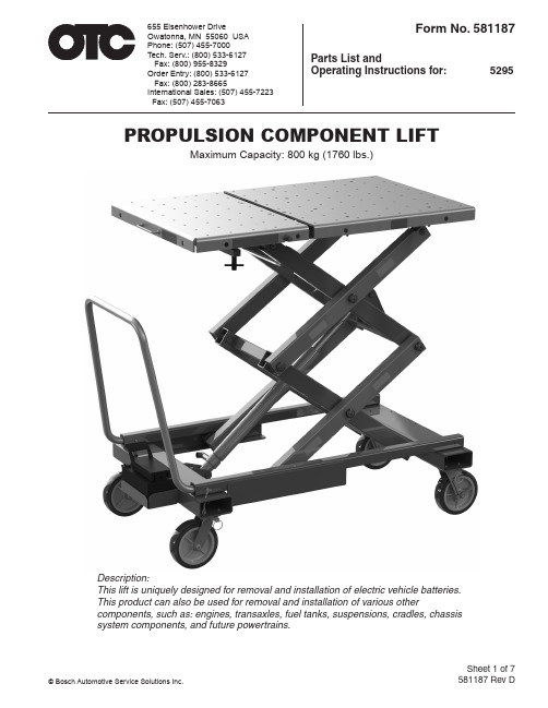
Sheet 1 of 7 581187 Rev DPROPULSION COMPONENT LIFTMaximum Capacity: 800 kg (1760 lbs.)Description:This lift is uniquely designed for removal and installation of electric vehicle batteries.This product can also be used for removal and installation of various othercomponents, such as: engines, transaxles, fuel tanks, suspensions, cradles, chassissystem components, and future powertrains.Parts List and Operating Instructions for: 5295Form No. 581187655 Eisenhower Drive Owatonna, MN 55060 USA Phone: (507) 455-7000Tech. Serv.: (800) 533-6127 Fax: (800) 955-8329Order Entry: (800) 533-6127 Fax: (800) 283-8665International Sales: (507) 455-7223Fax: (507) 455-7063© Bosch Automotive Service Solutions Inc.Back Sheet 1 of 7Safety PrecautionsWARNING: To prevent personal injury or equipment damage,●Study, understand, and follow all instructions before operating this device.●Wear eye protection that meets OSHA and ANSI Z87.1 standards.●Only qualified personnel shall perform inspections and repairs to this lift.●Before using lift, inspect the lift for bends, cracks, dents, elongated holes, or missinghardware. If damage is found, discontinue use.●Use only those repair parts called out in the parts list in this document. Items foundin the parts list have been carefully tested and selected.●Do not exceed the rated capacity of lift or platform extension.●Do not raise or lower lift with platform extended.●Use only on a hard, level surface.●Do not raise or move a load having a center of gravity extending beyond the wheels.Tipping can result in personal injury.●Do not move lift while a load is raised. Carefully and slowly move the load on inclinesor around corners. T ipping can result in personal injury. Lower load completely beforestorage.●Do not stand under a load supported by the lift.●Secure component in place before removing it from the lift.●No alterations shall be made to this product as this will void the warranty.Pump●Do not exceed the hydraulic pressure rating noted on the pump data plate or tamperwith the internal high pressure relief valve. Creating pressure beyond the ratedpressure can result in personal injury.●Before replenishing the fluid level, retract the system to prevent overfilling the pumpreservoir. An overfill can cause personal injury due to excess reservoir pressurecreated when cylinders are retracted.Explanation of Safety Signal WordsThe safety signal word designates the degree or level of hazard seriousness.DANGER : Indicates an imminently hazardous situation which, if not avoided, will result in death orWARNING : Indicates a potentially hazardous situation which, if not avoided, could result in death orCAUTION : Indicates a potentially hazardous situation which, if not avoided, may result in minor or moderate injury.CAUTION : Used without the safety alert symbol indicates a potentially hazardous situation which, if not avoided, may result in property damage.Sheet 2 of 7Preparation and Set UpUnpackaging1. Cut shipping banding from carton and platform.2. Install lift handle into base frame weldment and secure in place with cotterless hitch pins.3. Remove the wood chocks from around the caster wheels.4. Carefully roll the lift off the shipping pallet onto the floor.Prepare The Air Pump For OperationA. Pictogram DefinitionsB. Cut shipping tie straps from air pump.C. Air Supply Hook Up1. Remove the thread protector from the air inlet of the pump. The pump's air inlet is 1/4-18 NPT internal threads. Select and install the threaded fittings which are compatible with your air supply fittings. The air supply should be 20 CFM (.57 M³/min.) at 100 PSI (7 BAR) at the pump to obtain the rated hydraulic pressure. Air pressure should be regulated to between 50 PSI (3.5 BAR) and 140 PSI (9.5 BAR). A pressure of 100 PSI (7 BAR) is the recommended minimum. Secure your pump fitting to the air supply.2. It is highly recommended to install an automatic air line oiler to the air supply as close to the pump as possible. Set the unit to feed approximately one drop of oil per minute into the system. Use SAE grade oil, 5W to 30W.D. Priming The Pump UnitUnder certain circumstances it may be necessary to prime the air pump. To accomplish this, perform the following procedure:1. Press the release end of the pedal while holding downthe air intake valve with a flathead screwdriver. The air2. Allow the pump to cycle approximately 15 seconds.pedal once more.4. If the cylinder extends or pressure builds, the pump hasbeen successfully primed. If the pump does not respond,Activating the pump with the pedal end marked with this pictogram,the flow of fluids is directed out of the reservoir.Activating the pump with the pedal end marked with this pictogram,the flow of fluids is directed back to the reservoir.Air Intake Valve Filler/Vent Cap Air Inlet(1/4-18 NPT internal)Back Sheet 2 of 7Functional Check of LiftWithout external load applied to lift platform, fully raise and lower multiple times to ensure proper function of the hydraulic system and scissor components.1.extension.2.full collapse.3. Ensure platform raises and lowers only when the air pump foot pedal is actively depressed by the operator.WARNING: To prevent personal injury and/or equipment damage, if platform moves after air pump pedal is released, discontinue use and service immediately.Preparation of Other FeaturesA. Platform Tilting Features1. Turn forcing screws in/out fully to ensure proper function of platform tilting feature. See Figure 1 of “Fine Adjustment Tilting Feature” section.B. Stabilization Feature 1. Insert leveler screws into sockets (approx. 5 turns). Leveler screws should not project above steel tube or contact platform underside when not in use. See Figure 2 of “Stabilization Feature” section.C. Platform Sliding Extension Feature1. Cut shipping banding securing platform halves2. Retract spring plunger and extend platform by pulling on table handle. Ensure spring plunger engages at all three stop positions when the plunger is released.Operating InstructionsFine Adjustment Tilting FeatureThe forcing screws shown in Figure 1 allow the user to finely tilt the platform to help remove or install vehicle components. This feature provides a total of two inches of tilt at the front of the platform which helps compensate for uneven shop floors, difficult fastener locations, etc. The forcing screws can be operated by either hand, or wrench or socket, depending on the applied load.CAUTION: To prevent equipment damage, do not tilt the platform without the leveler screws in their lowest position as the platform might be driven into the screws.Figure 1Forcing ScrewsSheet 3 of 7Figure 2Leveler ScrewsStabilization FeatureIf lift is to be used as a stationary work surface for servicing components, two leveler screws (see Figure 2) have been added to help stabilize the platform.When the desired tilt or platform position has been reached, thread both leveler screws inward until they meet the bottom of the platform and tighten finger-tight only. This provides two extra points of contact for a more stable platform.CAUTION: To prevent equipment damage,• Do not tighten the leveler screws with a wrench or ratchet.• Do not tilt the platform if the leveler screws are not in their lowest position.Platform Sliding Extension FeatureWhen the lift is to be used as a stationary work surface, the sliding platform extension may be used to facilitate the separation of powertrain components (i.e., engine and transmission). Retract spring plunger and pull on T able Handle (See Figure 3) to extend sliding platform. Release spring plunger and slide platform extension until it locks into a stationary position.Secure components to the platform with bolts and/or straps. Many M10 x 1.5 holes are provided in the platform top to thread bolts into. CAUTION: To prevent damaging threads in the platform, do not torque bolts beyond 50 ft. lbs. (68 N•m). Holes in the side edges of the platform are provided for securing straps.●Always secure components to the platform with bolts and/or straps.●Do not raise or lower lift with platform extended.●Do not use the Platform Handle (located on the sliding platform) to move the entire lift.Figure 3Platform HandleSpringPlungerM10 x 1.5 holes to secure componentsHoles for strapsOperating The Lift To Remove Components1. Always follow the vehicle manufacturer’s recommended service procedure for removal of the component.2. Position the lift under the vehicle. Connect the air hose to the air pump.3.4. Remove any remaining bolts from the vehicle component.5.6. Move the lift and load out from under the vehicle.Operating The Lift To Install Components1. Position the lift under the vehicle chassis.2.raise the lift.3. Always follow the vehicle manufacturer’s recommended service procedure for installing the component.Inspection and Maintenance•Only qualified personnel shall perform inspections and repairs to this lift.•Before each use, inspect the lift for bends, cracks, dents, elongated holes, or missing hardware. If damage is found, discontinue use.•Use only those repair parts called out in the parts list in this document. Items found in the parts list have been carefully tested and selected.InspectionBefore each use, an approved inspector must inspect the lift for bends, cracks, dents, elongated holes, or missing hardware. If damage is found, discontinue use.RepairWhen repairing the lift, use only those repair parts called out in the parts list in this document. Items found in the parts list have been carefully tested and selected.DisposalAt the end of the useful life of the lift, dispose of the components according to all state, federal, and local regulations.Preventive MaintenanceNOTE: 1 cycle = 1 complete raising and lowering of the lift platform.Every 300 cycles or 6 months, whichever comes first:A. Hydraulic Cylinder1. Inspect for hydraulic fluid leaks.●Some oil accumulation on cylinder rod is normal and desired for proper function of the unit.●If fluid is escaping and puddling on the floor, the cylinder requires servicing.2. Without load applied to platform, raise and lower lift multiple times. If cylinder pulses, sticks, orgenerally doesn't operate smoothly, unit needs servicing.Back Sheet 3 of 7Preventive Maintenance continuedB. Hydraulic Fittings1. Inspect for leaks.●Tighten fittings to stop leak.●Replace fittings if tightening does not stop leak.C. Hose1. Inspect and replace if found to contain cuts, cracks, or considerable surface wear.D. Pump1. Check hydraulic fluid level.●The fluid level should be 1/2 inch (12.7 mm) from the filler/vent cap with cylinder retracted.Replenish with hydraulic fluid (P/N 9637) through this port if needed.2. Check pump reservoir for leaks due to damage to reservoir.3. Raise and lower platform by operating air pump pedal. Ensure platform raises and lowers only whenWARNING: To prevent personal injury and/or equipment damage, discontinue use and service the unit immediately if platform moves after air pump pedal is released.4. If platform moves slowly when raising, or pump seems to reciprocate faster than normal, install anautomatic air line oiler prior to the pump.●When automatic air line oiler is installed, some oil discharge from pump exhaust is normal andindicates proper lubrication.E. Lubrication1. Use a grease gun to thoroughly apply grease at every location fitted with grease fitting (i.e., upper& lower rollers, casters, scissor & hydraulic cylinder pivot pins, etc.). Pump grease into fitting until only new grease can be seen escaping from joint. Wipe away excess.F. Cleaning1. Wipe dirt, debris, and grime from all surfaces using clean rag.Every 3000 cycles or 24 months, whichever comes first:A. Draining and Flushing the Pump Reservoir1. Remove screws that fasten pump assembly to reservoir. Remove pump assembly from reservoir.Do not damage gasket, filter or safety valve.2. Drain reservoir of all fluid and refill half full with clean hydraulic fluid (P/N 9637). Rinse filter clean.3. Place pump assembly back onto reservoir, and secure with two machine screws assembled inopposite corners of housing.4. Run unit for several minutes. Use same method described in section titled “Priming the Pump Unit.”5. Drain and clean reservoir once more.6. Refill reservoir with hydraulic fluid (p/n 9637) and replace pump assembly (with gasket) on reservoirand install screws. Torque screws to 25 to 30 inch pounds (2.8 to 3.4 N•m).B. Refilling the Pump Reservoir1. If additional fluid must be added to reservoir, use only hydraulic fluid (p/n 9637; 215 SSU @ 100°F [38° C]). Clean entire area around filler plug before adding fluid to reservoir. Remove filler plug,and insert a clean funnel with filter. The cylinder must be fully retracted and air supply disconnected when adding fluid to reservoir.Sheet 4 of 7Back Sheet 4 of 7Parts List Item Part N o. N o.N o. Req'd Description 1Ý 2 Warning Decal 2Ý 2 Warning Decal 3579255 1 Base Weldment 4579251 1 Lower Left Scissor Weldment 5 Ý 8 Warning Decal 6 5641181 Elbow 7Ý 4 Caster Swivel Lock 8Ý 4 Swivel Caster With Brake 9Ý 1 Decal 10SP04506444 1 Air/Hydraulic Pump 11 579254 1 Lower Right Scissor Weldment 12Ý 1 Warning Decal 13579134 1 T able Top, Split40 14579136 1 T able Top, Split60 15Ý 2 Cotterless Hitch Pin 16Ý 14" Sash Chain 17 Ý 2 Split Ring Ý See Replacement Kit List13245679See Detail A Detail A16UUItem Part N o.N o. N o. Req'd Description18 Ý 4 Eccentric Guide19 Ý 4 Hex Head Cap Screw20 579131 1 T able Top Weldment21 SP04506434 1 Hydraulic Cylinder22 564117 1 Velocity Fuse23 579259 1 Hydraulic HoseÝ See Replacement Kit ListDetail BSeeDetail BUUSheet 5 of 7Back Sheet 5 of 7 ItemPart N o. N o.N o. Req'd Description 24578891 1 Riser Frame Weldment 25564060 2 Frame Tube Weldment 26579553 2 Forcing Screw Assembly 27579152 1 Riser Frame Weldment 28Ý 18 Serrated Flange Bolt(3/8-16 x 3/4") 29566055 1 In-line Flow Regulator Valve(Install valve with arrow pointingtowards the pump body.) 3010623 1 Hex Nipple Straight Fitting 31579264 1 Air Pump T ray 32Ý 8 Ball Caster (.625") 33 579131 1 Table Top Weldment ÝSee Replacement Kit ListSee Detail C(See note below)Detail D242528313233Sheet 6 of 7See Detail ESee Detail FSee Detail GSee Detail HDetail EDetail FDetail GDetail H353637383924254344142 Item Part N o. N o. N o. Req'd Description 34 579188 4 Roller35 Ý 13 Retaining Ring 36 579257 2 Table Keeper37 578798 1 Table Base Weldment38 Ý 16 Grease Fitting (Alemite) 39 Ý 6 Pivot Pin40 564076 8 Hex Lock Nut41 Ý 5 Retaining Ring 42Ý 2 Cylinder Pivot PinÝ See Replacement Kit ListSection Z-Z56Item Part N o.N o. N o. Req'd Description43 579126 1 T able Handle44 578940 1 T able Top Hinge45 Ý 2 Socket Head Shoulder Screw46 Ý 2 L ocknut(Nylon)47 Ý 2 Cap Screw48 579012 2 Center Guide Bar49 579011 2 Spacer50 Ý 6 Flat Head Socket Screw (.313-18)51 10230 10 Washer (5/16")52 Ý10 L ocknut53 Ý 3 Center Rod Mount54 Ý 2 Flange Nut55 579768 1 Spring Plunger Pin (.375")56 Ý 4 Flat Head Socket Screw (.313-18)57 Ý 2 Roll Pin58 216432 1 Hinge Nut (.625"-18)Parts Included But Not Shown578896 1 HandleÝ See Replacement Kit ListBack Sheet 6 of 7Sheet 7 of 7Replacement Kit ListItem N o. Qty. Description579905 Chain, Pin, Ring Kit15 2 Cotterless Hitch Pin16 14" Sash Chain 172 Split Ring579906 Pivot Pin Hardware Kit35 4 Retaining Ring38 2 Grease Fitting (Alemite) 392Pivot Pin579907 Hardware Kit45 2 Socket Head Shoulder Screw 46 2 Locknut (Nylon) 47 2 Cap Screw 50 6 Flat Head Socket Screw (.313-18) 52 10 L ocknut 54 2 Flange Nut 57 2 Roll Pin579908 Guide Kit18 4 Eccentric Guide194Hex Head Cap ScrewItem N o. Qty.Description579909 Decal Kit1 2 Warning Decal 2 2 Warning Decal 5 8 Warning Decal 9 1 Decal 12 1 Warning Decal579910 Cylinder Pin Hardware Kit41 4 Retaining Ring 422Cylinder Pivot Pin579911 Center Mount Pack533Center Rod Mount579912 Caster Kit7 1 Caster Swivel Lock81Swivel Caster With Brake579913 Bolt Pack286Serrated Flange Bolt (3/8-16 x 3/4")579915 Ball Caster Pack324Ball Caster (.625")IMPORTANT PRODUCT INFORMATIONRecord serial number and year of manufacture for future reference. See product identification label on unit for information.Serial Number:Year of Manufacture:Get parts at This document contains product parts lists and information regardingoperation and maintenance. Items listed in the parts list have been carefully tested and selected by OTC. Therefore, use only OTC replacement parts.Product questions may be directed to the OTC Technical Service Department at (800) 533-6127.。
- 1、下载文档前请自行甄别文档内容的完整性,平台不提供额外的编辑、内容补充、找答案等附加服务。
- 2、"仅部分预览"的文档,不可在线预览部分如存在完整性等问题,可反馈申请退款(可完整预览的文档不适用该条件!)。
- 3、如文档侵犯您的权益,请联系客服反馈,我们会尽快为您处理(人工客服工作时间:9:00-18:30)。
动力动力电电池池系系统统使用用户手手册册
为了便于使用及质保,请仔细阅读并随车妥善保管
目录
安全须知
01
紧急事故处理
02
术语解释
04
第1章 使用说明
04
1.0 电池温度特性
04
1.1 出车前检查
05
1.2 正常运营车辆的使用要求
05
1.3 机动运营车辆的使用要求
06
1.4 久放不用车辆的使用要求
● 如检查发现异常,请联系我司售后部
或服务站获得帮助,切勿擅自维修。
7
第1章 使用说明
1.8 手动维护开关的作用
1、手动维护开关是一种用于手动切断高压线路,起到安全保护功能的橙色电器元件(见右图)。 2、相关人员在对车辆进行检修作业前,需先断开手动维护开关,检修作业完成后,需确保手动
维护开关安装到位。
1.5 充电机的使用要求
● 必须使用符合国家标准的充电机。 ● 充电时请使用“自动充电”功能,严禁使用“手动充电”功能,严禁带载拔枪。
6
第1章 使用说明
1.6 电池保养的操作方法
● 保养场地要求:宽敞平整安全,要有充电设备。 ● 保养操作流程:
步骤一 调整电池电量(SOC)在25%~40%区间。 步骤二 车辆停稳,关闭电源(钥匙拧至OFF档),然后启动电源
第1章 使用说明
为了保证您的电池系统长期安全可靠的运行,请您仔细阅读并遵守以下使用说明:
1.0 电池温度特性
● 工作环境温度: -30℃~55℃ ● 存储环境温度: -40℃~55℃ ● 最佳充放电温度: 25℃~45℃
4
第1章 使用说明
1.1 出车前检查
观察车辆仪表盘,确认电池系统状态正常,无任何报警信息。 当SOC值大于50%时,出车较好;若条件允许,建议满充后出车。 当SOC值小于30%时,电量较低,应充电至50%以上方可出车。
1.9 手动维护开关操作规范 1.9.1 拆卸维护开关的步骤
步骤一 如图1所示,用左手拇指向下按压A箭头标记的卡扣位置,同时用右手拇指沿着B箭头所示的方向掰开维护开 关的拉手至图2中所示的角度。
步骤二 如图2所示,继续用左手拇指向下按压A箭头标记的位置,同时用右手拇指沿着B箭头所示的方向继续掰开维护 开关的拉手至图3中所示的角度,即拉手与维护开关成90度夹角。
表1:易损件质量保修期清单
序号 1 2 3 4
名称 继电器 风扇 MSD 保险
质保期(月) 里程(万公里)
24
15
12
8
36
18
3
2
2.3.2 售后市场销售配件的质量保修期
1、销售配件的定义:客户向CATL指定配件销售商采购的零部件。
表2:销售配件质量保修期清单
2、质量保修期的起始:以“CATL售后服务部或服务代理商”开具的 序号
场景·火灾
第一步 人员迅速离开车辆,根据现场情况拨打报警电话。 第二步 保证人身安全的情况下,有条件的进行如下操作:
1)如果电池线束冒烟起火,使用二氧化碳或者干粉灭火器喷射。 2)如果电池起火,在远距离使用高压水枪灭火。 3)如果不慎吸入浓烟,请尽快转移并就医。 第三步 通知汽车所属品牌经销商,获取进一用要求
06
1.6 电池保养的操作方法
07
1.7 定期检查要求
07
1.8 手动维护开关的作用
08
1.9 手动维护开关操作规范
09
第2章 质保说明
10
2.0 保养登记卡须知
10
2.1 质保服务承诺
10
2.2 质量保修规定
11
2.3 质量保修期
12
2.4 质量保修责任豁免范围
13
安全须知
1.2 正常运营车辆的使用要求
纯电动车每三日至少做一次自动满充电。 每日累计充电电量,尽量不超过额定总电量的1.5倍。 仪表盘提示电池需保养时,请尽快进行“电池保养”,使电池系统恢复到正常状态。 车辆必须每三个月做一次“电池保养”,防止造成电池损伤,具体保养操作方法参见1.6节。 车辆未按要求使用造成电池损坏,将不享受三包政策。
步骤二 如图2所示,使用左右手的拇指沿着B箭头所示的方向缓慢推动维护开关的拉手, 直到听见“咔嚓”声后停 止,如图3所示,此时维护开关安装到位。
步骤三 如图4所示,用右手握住维护开关的上盖沿着A箭头所示的方向拉拨,以此确认维护开关的上盖是否安装 到位。
9
第2章 质保说明
2.0 保养登记卡须知
1、本卡由CATL服务代理商或售后服务人员填写,无代理商签章或售后服务人员签字,该保养卡无效。 2、本卡是用户享受产品质量保修服务的凭证,请务必认真填写“保养登记卡”内容,以便充分享受质保服务。 3、本卡不得转借、涂改,遗失不补发,请妥善保管。 4、本卡一式三联,详见本手册第20-22页。
提示
● 夏季高温天气下,白天补电次数不超过2次,每次时间不超过30分钟;若补电时间超过30分钟,
仅允许补电1次。以避免电池高温影响到正常运营。
5
第1章 使用说明
1.3 机动运营车辆的使用要求
● 使用要求与正常运营车辆相同。
提示
● 当气温在0℃及以下,运营车辆收车后应尽快充电,以防止电池温度过低后充电时间延长,影响运营。
1、本手册的所有规定仅适用于在中国大陆地区(不含港、澳、台)销售并使用的CATL动力电池系统。 2、在质量保修期内,CATL对其认可的量产车型因电池系统的质量缺陷所引起的故障,由CATL提供质量保修服务。 3、对于超过质量保修期的产品,CATL提供有偿服务。 4、任何不属于CATL责任的故障,均不在质量保修的责任范围内。 5、在质量保修期内,由CATL免费更换下来的故障件产权归CATL所有。 6、除中国法律的强制性规定外,本手册规定提供的质量保修服务是本公司对客户承担的唯一责任。
提示 ● 凡同时标注时间和里程者,均已先到者为准。
12
第2章 质保说明
2.4 质量保修责任豁免范围 CATL对如下情况不提供质量保修服务:
1、 未按本手册的规定进行正确使用、保养、检查产品而导致的损坏。 2、 手动维护开关(MSD)未安装到位而造成的损坏。 3、 车辆未按本手册第一章节的使用要求操作而导致的各类故障情形。 4、 使用不符合国家标准的充电设备或充电操作不规范而导致的损坏。 5、 非电池系统故障引起的交通事故而导致的损坏 6、 动力电池系统浸泡在水中的时间超过30分钟。 7、 未经CATL的售后服务部、服务站授权,私自改装、加装、拆装电池系统导致的损坏由拆装方负责。 8、 电池系统发生故障时,客户未经CATL售后服务部或服务站允许私自对故障进行处理而导致的损坏。 9、 客户因无法使用车辆所造成的关联或间接损失,如时间、停车、差旅费、个人财物或商业财产损失、收益损失、精
13
服务站
序号 省份 城市
服务代理商名称
服务站负责人
固定电话
移动电话
服务站地址
1
安徽 临泉 临泉县工业园区万里达汽车修配厂
齐保民
0558-6311188 15055830199 临泉县工业园区邢塘集西头S102省道
2
广东 惠东
惠东县粤惠运输有限公司
郑尉昌
0752-8862331 18927336478
神损失等,但依法判定由本公司承担的情况除外。 10、因不可抗力如地震、台风、洪水、化学污染、雷击、冰雹、泥沙、飞石、火灾、政治灾难,或人为的故意损坏等因
素导致的损坏,以及基于这些损坏而引起的二次赔偿,双方均予以免责。
CATL在法律许可下拥有对本手册的最终解释权,保留修改本手册的权利,如有变动恕不另行通知。
配件发票上的日期开始计算。
1
2
3、销售配件在质量保修期内免费维修或更换后的质量保修期等于原销 3
4
售配件规定的质保期的剩余期限。
名称 继电器 风扇 MSD 保险
质保期(月) 里程(万公里)
24
15
12
8
36
18
3
2
4、电池箱总成的质保期等于整车规定质保期的剩余期限。 5、销售配件质量保修期清单参见表2。
2.1 质保服务承诺
1、服务目标:追求卓越,创造世界一流服务体系。 2、服务口号:用心服务,E路领先。 3、服务原则:结果导向,快速服务。 4、服务信念:客户永远是对的。
提示
● 新车上线时,请致电400-918-0889,CATL将免费提供一次新车上线检查。
10
第2章 质保说明
2.2 质量保修规定
惠东县平山镇旱坑仔50米路边
3
广东 东莞 东莞市捷盛汽车设备有限公司
张文杰
0769-22188221 13592762788 东莞市道滘镇昌平村扶屋水组横路
4
广东 广州
广州市黄埔区炳胜修配厂
吴汉华
020-82088182 13434151289
广州市黄埔区隔墙路自编16号
广州市南沙区南沙街虎门联络道塘坑路
1.4 久放不用车辆的使用要求
● 电池存放的最佳SOC区间:40%~80%。 ● 电池系统的存放环境要求通风、干燥、不受阳光直晒、不受雨淋、远离热源。 ● 车辆必须每三个月做一次“电池保养”,防止造成电池损伤,具体保养操作方法参见1.6节。 ● 久放车辆首次使用前,为激活电池系统至少需要做一次"电池保养",以恢复电池的性能到最佳状态。
提示
● 如果因充电异常引起的火灾,务必第一时间关闭充电电源,再执行下一步灭火动作。
2
紧急事故处理
场景·车辆涉水
涉水须知
车辆在积水路面行驶时,需注意如下:
深度
速度
时间
<=30Cm <=10Km/h <=10Min.
注:若路面积水深度 >30cm , 禁止通过。 浸泡须知