萨牌双交流电控DUAL_AC2说明书
萨牌仪表说明书

萨牌仪表说明书1 特性1.1 特点1( 萨牌MDI多功能数字仪表是一个显示器,它适用于所有装有ZAPI高频电控器的各种形式的电动车辆。
2( 萨牌MDI多功能数字仪表的信号取自斩波器,而不是电瓶,这样不同电压等级的车辆也可用同一仪表。
3( 电瓶的放电状态由微处理器进行一定的换算模拟获得。
该换算考虑了制动及起动等大电流工况对电瓶的影响。
4( 用萨牌MDI数字式手持单元,可以选择100种不同放电曲线。
5( 萨牌MDI 多功能数字仪表是一个以微处理器为基础的系统。
对电瓶放电状态测量是高精度的,具有很高的可靠性和灵敏度。
同时萨牌MDI多功能数字仪表还可以显示工作小时。
6( 萨牌MDI多功能数字仪表有三个内部功能。
, 显示放电状态。
, 工作小时。
, 显示控制系统故障。
7( 萨牌MDI多功能数字仪表不直接连到电瓶,她仅与斩波器相连。
与传统显示仪表相比,萨牌MDI多功能数字仪表无需复杂接线,也节省了安装时间。
1.2 显示功能说明1.2.a 发光二极管显示功能萨牌MDI多功能数字仪表用发光二极管显示电瓶放电状态。
萨牌MDI多功能数字仪表有五个发光二极管,一红四绿,表示电瓶的放电状态。
充足电时,四个绿色发光二极管全亮。
随着电瓶不断放电,四个绿灯随电瓶剩余电量的减少逐步并按一定顺序熄灭,直至电瓶放完电,红灯开始闪烁,表示电瓶已开始过放电,斩波器进入低电压保护状态。
1.2.b 液晶显示功能小时计:在萨牌MDI多功能数字仪表中部装有液晶显示器,它可以用来显示 1( 工作小时2( 系统故障,萨牌MDI多功能数字仪表显示故障状态时是以相应的代码表示,故障发生时,红色发光二极管将开始闪烁,以引起注意。
3( 软件版本:电锁刚闭合时,萨牌MDI多功能数字仪表显示EPROM中的软件版本,即EP××,同时出现扳手图案。
4( 其它信息,萨牌MDI多功能数字仪表上有三种图案,分别告知司机下列信息:乌龟图案:表示车辆处在“软”方式工作状态,在这种状态下,最大速度和加速度都被减小了。
萨奥使用手册说明(调试)
1.使用手册说明该手册含概了对操作方法的说明,它对于了解如何安装和操作该装置是十分必要的。
本手册是为最终用户/顾客服务的。
该手册及其所有相关文件是由明尼阿波利斯市的Sauer-Danfoss公司编写并将由该公司享有改进维护的权力。
所有的改动将和Sauer-Danfoss公司同步。
2.修改记录3.机器图片4.操作说明4.1 概述该系统的输入值包括一个内含行驶速度电位计的FNR控制手柄,一个最大行驶速度的电位计,和一个转向电位计。
在两个驱动马达上的速度信号以脉冲的形式反馈给控制器。
还有开关输入,可以实现行驶/摊铺模式,停车制动状态,高/低速空转状态,和标准模式状态。
系统输出由四个单向阀驱动装置构成。
机器的每一条履带都有一个相应的向前和向后的阀驱动器。
这些驱动的双盘绕的EDC阀安装在泵上。
还有一个RS232的连续端口,它一般用来驱动2x24字符文字显示器,为操作者提供信息。
这种一样的连续端口可以交替的与膝上型电脑连接运行WebGPL。
最大行驶速度电位计的位置,将会为摊铺机设定允许的最大摊铺速度。
这是一个正常最大行驶速度的百分值。
正常最大行驶速度取决于系统处于摊铺还是空行驶模式。
空行驶模式时,两个马达处于最小排量的位置。
摊铺模式时,两个马达处于最大排量的位置。
在所有操作模式下,FRN手柄将会选择一个行驶方向和一个最大值的百分数,从而使其得到一个综合的行驶速度。
行驶电位计将为控制系统提供一个行走命令。
当电位计处于中点时,将没有行驶方向的命令,这时摊铺机将会以直线行驶。
以反时针方向转动电位计将会使摊铺机向左行驶。
左边的履带会减速而右边的履带会加速的程度取决于电位计被旋转多少。
这会保持一个连续的行驶速度。
如果右边履带达到最大速度,而且不能再增加,在这种情况下,随着行驶命令的增加,左边履带会继续减速,而右边履带一直以最大速度行驶。
于是整机的速度随之改变。
如果左边履带倒退,机器进入反旋转模式。
如果以顺时针方向旋转电位计,右边履带也会出现相同情况。
SAMCO-VM05系列变频器中文操作说明书

由衷地感謝您購買日本サンケン(S A N K E N )牌32位元R I S C 架構、具有V /F 控制模式與Se n s o r l e s s �或稱速度推算式、無速度傳感式�向量控制模式可供選擇的S A M C O -v m 05系列雙重額定、高性能、靜音型汎用變頻器。
裝設這部變頻器之後�您的三相感應馬達立刻具有無段變速的機能。
由於32位元R I S C 演算速度快、程式容量大�因此具備多機能、操作容易的特點。
為了讓您充分地享用這部變頻器的特性與機能�務必詳閱這本操作說明書。
當您使用中發現任何疑難時�請立刻就近向士林電機的F A 產品經銷商洽詢�或撥電話�03�597-0921轉231~233通知士林電機自動化營業部營業三課�我們的專業人員隨時都等待著為您做熱誠地服務。
在此我們再度深切地期望您永遠愛顧 的優良產品。
台灣總代理�士林電機廠股份有限公司安全通告●為了要預先防範您以及第三者因採用本產品而導致對人體危害或財產損失�因此在這本操作說明書上明確地登載著各種警告與禁制事項�請務必遵守。
使用本產品以前請務必詳閱這本操作說明書�並請依照正確的方式使用。
●這本操作說明書務必放置在設備、機台的旁邊或是便於取閱的地方�以便使用者查閱。
●對於安全注意事項等級�在說明書內分為「危險」、「注意」兩級。
操作人員如果不理會而誤操作時�可能會造成人體傷害或對財物造成損失的事項。
注意操作人員如果不理會而誤操作時�可能會對人體造成傷亡事件的事項。
危險※還有�即使是「注意」所記載內容都是屬於必需遵守的重要事項�不予理會時亦可能會引發不可臆測的後果。
標誌之後所敘述的是具體的強制內容。
強制�不可不為�標誌標誌之後所敘述的是具體的禁止內容。
禁止�不可為�標誌標誌之後所敘述的是具體的注意內容。
注意標誌標誌之後所敘述的是具體的危險內容。
危險標誌標誌解說安全注意事項1.請採用3-2-(1)所指定的螺絲�將變頻器牢牢地固定在平整的水泥或金屬板類的牆面上�並加以適當地屏蔽。
Lincoln Dual Maverick 450 产品说明书

Operator’s ManualRegister your machine:/registerAuthorized Service and Distributor Locator: /locatorIM10537 | Issue D a te May -21© Lincoln Global, Inc. All Rights Reserved.For use with machines having Code Numbers:12881Need Help? Call 1.888.935.3877 to talk to a Service Representative Hours of Operation:8:00 AM to 6:00 PM (ET) Mon. thru Fri.After hours?Use “Ask the Experts” at A Lincoln Service Representative will contact you no later than the following business day.For Service outside the USA:Email:*********************************Save for future referenceDate PurchasedCode: (ex: 10859)SECTION A:WARNINGSC ALIFORNIA PROPOSITION 65 WARNINGSWARNING: This product, when used for welding or cutting, produces fumes or gases which contain chemicals known to the State of California to cause birth defects and, in some cases, cancer. (California Health & Safety Code § 25249.5 et seq.)ARC WELDING CAN BE HAZARDOUS. PROTECTYOURSELF AND OTHERS FROM POSSIBLE SERIOUS INJURY OR DEATH. KEEP CHILDREN AWAY.PACEMAKER WEARERS SHOULD CONSULT WITH THEIR DOCTOR BEFORE OPERATING.Read and understand the following safety highlights. For additional safety information, it is strongly recommended that you purchase a copy of “Safety in Welding & Cutting - ANSI Standard Z49.1” from the American Welding Society, P.O. Box 351040, Miami, Florida 33135 or CSA Standard W117.2-1974. A Free copy of “Arc Welding Safety” booklet E205 is available from the Lincoln Electric Company, 22801 St. Clair Avenue, Cleveland, Ohio 44117-1199.BE SURE THAT ALL INSTALLATION, OPERATION,MAINTENANCE AND REPAIR PROCEDURES ARE PERFORMED ONLY BY QUALIFIED INDIVIDUALS.FOR ENGINE POWERED EQUIPMENT.1.a.Turn the engine off before troubleshootingand maintenance work unless themaintenance work requires it to be running.1.b.Operate engines in open, well-ventilated areas or vent the engineexhaust fumes outdoors. 1.c.Do not add the fuel near an open flame weldingarc or when the engine is running. Stop the engine and allow it to cool before refueling to with hot engine parts and igniting. Do not spill fuel when filling tank. If fuel is spilled, wipe it up and do not start engine until fumes have been eliminated.1.d. Keep all equipment safety guards, coversand devices in position and in good repair.Keep hands, hair, clothing and tools away from V-belts, gears, fans and all other moving parts when starting, operating or repairing equipment.1.e.In some cases it may be necessary to remove safety guards toperform required maintenance. Remove guards only when necessary and replace them when the maintenance requiring their removal is complete. Always use the greatest care when working near moving parts. 1.f. Do not put your hands near the engine fan. Do not attempt tooverride the governor or idler by pushing on the throttle control rods while the engine is running. 1.g.To prevent accidentally starting gasoline engines while turningthe engine or welding generator during maintenance work,disconnect the spark plug wires, distributor cap or magneto wire as appropriate. 1.h.To avoid scalding, do not remove the radiatorpressure cap when the engine is hot.ELECTRIC ANDMAGNETIC FIELDS MAY BE DANGEROUS2.a.Electric current flowing through any conductorcauses localized Electric and Magnetic Fields (EMF).Welding current creates EMF fields around welding cables and welding machines 2.b.EMF fields may interfere with some pacemakers, andwelders having a pacemaker should consult their physician before welding. 2.c.Exposure to EMF fields in welding may have other health effectswhich are now not known. 2.d.All welders should use the following procedures in order tominimize exposure to EMF fields from the welding circuit:2.d.1.Route the electrode and work cables together - Securethem with tape when possible.2.d.2.Never coil the electrode lead around your body.2.d.3.Do not place your body between the electrode and workcables. If the electrode cable is on your right side, the work cable should also be on your right side.2.d.4.Connect the work cable to the workpiece as close as pos-sible to the area being welded.2.d.5.Do not work next to welding power source.SAFETYConformanceProducts displaying the CE mark are in conformity with European Community Council Directive of 15 Dec 2004 on the approximation of the laws of the Member States relating to electromagnetic compatibility,2004/108/EC. It was manufactured in conformity with a national standard that implements a harmonized standard: EN 60974-10 Electromagnetic Compatibility (EMC) Product Standard for Arc Welding Equipment. It is for use with other Lincoln Electric equipment. It is designed for industrial and professional use. IntroductionAll electrical equipment generates small amounts of electromagnetic emission. Electrical emission may be transmitted through power lines or radiated through space, similar to a radio transmitter. When emissions are received by other equipment, electrical interference may result. Electrical emissions may affect many kinds of electrical equipment; other nearby welding equipment, radio and TV reception, numerical controlled machines, telephone systems, computers, etc. Be aware that interference may result and extra precautions may be required when a welding power source is used in a domestic establishment.Installation and UseThe user is responsible for installing and using the welding equipment according to the manufacturer’s instructions. If electromagnetic disturbances are detected then it shall be the responsibility of the user of the welding equipment to resolve the situation with the technical assistance of the manufacturer. In some cases this remedial action may be as simple as earthing (grounding) the welding circuit, see Note. In other cases it could involve construction of an electromagnetic screen enclosing the power source and the work complete with associated input filters. In all cases electromagnetic disturbances must be reduced to the point where they are no longer troublesome.Note: The welding circuit may or may not be earthed for safety reasons according to national codes. Changing the earthing arrangements should only be authorized by a person who iscompetent to access whether the changes will increase the risk of injury, e.g., by allowingparallel welding current return paths which may damage the earth circuits of other equipment. Assessment of AreaBefore installing welding equipment the user shall make an assessment of potential electromagnetic prob-lems in the surrounding area. The following shall be taken into account:a) other supply cables, control cables, signaling and telephone cables; above, below and adjacent to thewelding equipment;b) radio and television transmitters and receivers;c) computer and other control equipment;d) safety critical equipment, e.g., guarding of industrial equipment;e) the health of the people around, e.g., the use of pacemakers and hearing aids;f) equipment used for calibration or measurementg) the immunity of other equipment in the environment. The user shall ensure that other equipment beingused in the environment is compatible. This may require additional protection measures;h) the time of day that welding or other activities are to be carried out.The size of the surrounding area to be considered will depend on the structure of the building and other activities that are taking place. The surrounding area may extend beyond the boundaries of the premises. Methods of Reducing EmissionsMains SupplyWelding equipment should be connected to the mains supply according to the manufacturer’s recommenda-tions. If interference occurs, it may be necessary to take additional precautions such as filtering of the mains supply. Consideration should be given to shielding the supply cable of permanently installed welding equip-ment, in metallic conduit or equivalent. Shielding should be electrically continuous throughout its length. The shielding should be connected to the welding power source so that good electrical contact is maintained between the conduit and the welding power source enclosure.Maintenance of the Welding EquipmentThe welding equipment should be routinely maintained according to the manufacturer’s recommendations. All access and service doors and covers should be closed and properly fastened when the welding equip-ment is in operation. The welding equipment should not be modified in any way except for those changes and adjustments covered in the manufacturers instructions. In particular, the spark gaps of arc striking and stabilizing devices should be adjusted and maintained according to the manufacturer’s recommendations. Welding CablesThe welding cables should be kept as short as possible and should be positioned close together, running at or close to floor level.Equipotential BondingBonding of all metallic components in the welding installation and adjacent to it should be considered. However, metallic components bonded to the work piece will increase the risk that the operator could receive a shock by touching these metallic components and the electrode at the same time. The operator should be insulated from all such bonded metallic components.Earthing of the WorkpieceWhere the workpiece is not bonded to earth for electrical safety, not connected to earth because of its size and position, e.g., ships hull or building steelwork, a connection bonding the workpiece to earth may reduce emissions in some, but not all instances. Care should be taken to prevent the earthing of the workpiece increasing the risk of injury to users, or damage to other electrical equipment. Where necessary, the connec-tion of the workpiece to earth should be made by a direct connection to the workpiece, but in some countries where direct connection is not permitted, the bonding should be achieved by suitable capacitance, selected according to national regulations.Screening and ShieldingSelective screening and shielding of other cables and equipment in the surrounding area may alleviate prob-lems of interference. Screening of the entire welding installation may be considered for special applications1._________________________1 Portions of the preceding text are contained in EN 60974-10: “Electromagnetic Compatibility (EMC) prod-uct standard for arc welding equipment.”INSTALLATION...........................................................................................................................SECTION A TECHNICAL SPECIFICATIONS...................................................................................................................A-1 VRD (VOLTAGE REDUCTION DEVICE).......................................................................................................A-2 LOCATION AND VENTILATION..................................................................................................................A-3 STORING ............................................................................................................................................A-3 STACKING ............................................................................................................................................A-3 ANGLE OF OPERATION............................................................................................................................A-3 LIFTING ............................................................................................................................................A-3 HIGH ALTITUDE OPERATION....................................................................................................................A-4 HIGH TEMPERATURE OPERATION............................................................................................................A-4 TOWING ............................................................................................................................................A-4 VEHICLE MOUNTING................................................................................................................................A-4 PRE-OPERATION ENGINE SERVICE...........................................................................................................A-4 OIL ............................................................................................................................................A-4 FUEL - USE DIESEL FUEL ONLY...............................................................................................................A-5 ENGINE COOLANT...................................................................................................................................A-5 BATTERY CONNECTION...........................................................................................................................A-5 MUFFLER OUTLET PIPE...........................................................................................................................A-5 SPARK ARRESTOR...................................................................................................................................A-5 CASE FRONT CONTROLS.........................................................................................................................A-6 WELDING TERMINALS.............................................................................................................................A-8 WELDING OUTPUT CABLES......................................................................................................................A-8 MACHINE GROUNDING.............................................................................................................................A-8 REMOTE CONTROL .................................................................................................................................A-9 AUXILIARY POWER RECEPTACLES ..........................................................................................................A-9 STANDBY POWER CONNECTIONS............................................................................................................A-9 CABLE INDUCTANCE AND ITS EFFECTS ON WELDING..............................................................................A-9 CONNECTION OF WIRE FEEDERS WITH CONTROL CABLE (14 PIN)..........................................................A-10 CONNECTION OF ACROSS THE ARC WIRE FEEDERS TO THE DUAL MAVERICK®450 (AU) ......................A-11 ELECTRICAL CAUTIONS.........................................................................................................................A-12 OPERATION................................................................................................................................SECTION B GENERAL DESCRIPTION..........................................................................................................................B-1 FOR AUXILIARY POWER:..........................................................................................................................B-1 ENGINE OPERATION................................................................................................................................B-1 ADD FUEL ............................................................................................................................................B-2 HAND PRIMER BUTTON...........................................................................................................................B-2 RECOMMENDED APPLICATIONS..............................................................................................................B-2 GENERATOR............................................................................................................................................B-2 AUTO-START INSTRUCTION ....................................................................................................................B-2 BREAK-IN PERIOD ..................................................................................................................................B-2 ENGINE OPERATION................................................................................................................................B-3 TYPICAL FUEL CONSUMPTION.................................................................................................................B-3 WELDER OPERATION...............................................................................................................................B-4 PARALLELING..........................................................................................................................................B-6 AUXILIARY POWER OPERATION................................................................................................................B-7 DISPLAY OPERATION...............................................................................................................................B-8 ACCESSORIES............................................................................................................................SECTION C MAINTENANCE...........................................................................................................................SECTION D ROUTINE AND PERIODIC MAINTENANCE..................................................................................................D-1 ENGINE MAINTENANCE...........................................................................................................................D-1 AIR FILTER ............................................................................................................................................D-1 FUEL FILTERS.........................................................................................................................................D-3 COOLING SYSTEM...................................................................................................................................D-3 NAMEPLATES / WARNING DECALS MAINTENANCE..................................................................................D-3 WELDER / GENERATOR MAINTENANCE..................................................................................................D-3 FAN BELT CHANGE..................................................................................................................................D-3 OIL CHANGE............................................................................................................................................D-3 BATTERY HANDLING...............................................................................................................................D-4 PREVENTING ELECTRICAL DAMAGE.........................................................................................................D-4PREVENTING BATTERY DISCHARGE.........................................................................................................D-4 PREVENTING BATTERY BUCKLING...........................................................................................................D-4 CHARGING THE BATTERY........................................................................................................................D-4 BATTERY LOCKOUT SWITCH....................................................................................................................D-4 TROUBLESHOOTING...................................................................................................................SECTION E DIAGRAMS.................................................................................................................................SECTION F PARTS CONTENT/DETAILS MAY BE CHANGED OR UPDATED WITHOUT NOTICE. FOR MOST CURRENT INSTRUCTION MANUALS, GO TO .INSTALLATION DUAL MAVERICK®450 (AU)7. 15 AMP CIRCUIT BREAKER (2) -Auxiliary output breakerprotects the 230V, single phase receptacle.8.25 AMP CIRCUIT BREAKER - Auxiliary output breakerprotects the 400V, three phase receptacle.9. 230VAC SINGLE PHASE RECEPTACLE (QTY 2) -protected by15 Amp circuit breaker and is IP66 rated10. 400V THREE PHASE AUXILIARY PLUG -protected by a 25 Acircuit breaker and is IP66 rated11. POSITIVE AND NEGATIVE WELD TERMINAL OPERATOR A -Provides a connection point for the electrode and workcables.12. GLOW PLUG PUSH BUTTON -When pushed activates theglow plugs. Glow plug should not be activated for more than20 seconds continuously.13. RUN / STOP SWITCH -RUN position energizes the engineprior to starting. STOP position stops the engine. The oilpressure interlock switch prevents battery drain if the switch is left in the RUN position and the engine is not operating. 14. START PUSH BUTTON- Energizes the starter motor to crankthe engine.15. EMERGENCY STOP –Push to stop the engine immediately.The stop button needs to be manually reset after use in order to turn on the engine again.16. BATTERY BREAKER -For protection of Battery ChargingCircuit.17. LCD SCREEN, IP67 RATED OPERATOR B18. OUTPUT CONTROL OPERATOR B19. 6-PIN REMOTE CONTROL CONNECTION OPERATOR B20. WIRE FEEDER POLARITY SWITCH OPERATOR B21. 14-PIN WIRE FEEDER CONNECTION OPERATOR B22. RESIDUAL CURRENT DEVICE– 30mA- Instantly breaks theauxiliary circuit to prevent serious harm from an ongoingelectric shock.23. WIRE FEEDER CIRCUIT BREAKER- 42V WIRE FEEDERBREAKERS24. POSITIVE AND NEGATIVE WELD TERMINAL OPERATOR BWireDiameter Note: Select the maximum wire feed speed (WFS) that willbe used during the welding session to ensure poweroutput to the wire feeder is sufficient.ACCESSORIES DUAL MAVERICK®450 (AU)MAINTENANCE DUAL MAVERICK®450 (AU)outlet tube to create the critical seal, there will be some initial resistance, similar to breaking the seal on a jar. Gently move the end of the filter back and forth to break the seal then rotate while pulling straight out. Avoid knocking the filter Remove the FilterRotate the filter while pullingstraight out.If your air cleaner has a safety filter, replace it every third primary filter change. Remove the safety filter as you would the primary filter. Make sure you cover the air cleaner outlet tube to avoid any If your air cleaner is equipped with a Vacuator Valve Visually check and physically squeeze to make sure the valve is flexible and not inverted, damaged or plugged.Inspect the new filter carefully, paying attention to If you're servicing the safety filter, this should be seated into position before installing the primary filter.If the service cover hits the filter before it is fully in place, remove the cover and push the filter (by hand) further into the air cleaner and try again. The cover should go on with no extra force.slightly, adjust itself and distribute the sealing pressure evenly. To complete a tight seal, apply pressure by hand at the outer rim of the filter, not the flexible center. (Avoid pushing on the center of the urethane end cap.) No cover pressure is required to hold the seal.NEVER use the service cover to push the filter into place! Using the cover to push the filter in could cause damage to the housing, cover Visually inspect the old filter for any signs of leaks. A streak of dust on the clean side Inspect the OldFilter for Leak CluesInspect the New Filter for DamageInsert the New Radial Seal Filter ProperlyOuter edge of the outlet tubeInner edge of the outlet tubeWIRING DIAGRAM DUAL MAVERICK®450 (AU)DIMENSION PRINT DUAL MAVERICK®450 (AU)ATENÇÃOJapaneseChineseKoreanArabicREAD AND UNDERSTAND THE MANUFACTURER’S INSTRUCTION FOR THIS EQUIPMENT AND THE CONSUMABLES TO BE USED AND FOLLOW YOUR EMPLOYER’S SAFETY PRACTICES.SE RECOMIENDA LEER Y ENTENDER LAS INSTRUCCIONES DEL FABRICANTE PARA EL USO DE ESTE EQUIPO Y LOS CONSUMIBLES QUE VA A UTILIZAR, SIGA LAS MEDIDAS DE SEGURIDAD DE SU SUPERVISOR.LISEZ ET COMPRENEZ LES INSTRUCTIONS DU FABRICANT EN CE QUI REGARDE CET EQUIPMENT ET LES PRODUITS A ETRE EMPLOYES ET SUIVEZ LES PROCEDURES DE SECURITE DE VOTRE EMPLOYEUR.LESEN SIE UND BEFOLGEN SIE DIE BETRIEBSANLEITUNG DER ANLAGE UND DEN ELEKTRODENEINSATZ DES HER-STELLERS. DIE UNFALLVERHÜTUNGSVORSCHRIFTEN DES ARBEITGEBERS SIND EBENFALLS ZU BEACHTEN.。
Ae0zp0ba (AC0-ing)

INDEXPage 1Introduction (3)2Specification (3)2.1Technical specifications (3)2.2Control unit (4)2.2.a Microswitches (4)2.2.b Accelerator unit (4)2.2.c Other analog control unit (5)2.2.d Speed feedback (5)2.3Protection features (6)2.4Operational features (7)2.5Diagnosis (8)2.6Thermal consideration (8)2.7General instructions and precautions (8)2.8Susceptibility and electromagnetic emission (9)2.9Main contactor and emergency switch (9)3Installation (10)3.1Connection cables (10)3.2Contactors (10)3.3Fuses (10)3.4Description of connectors - Standard version (11)3.5Description of connectors - MDI PRC Version (13)3.6Encoder installation (15)3.7Description of power connections (16)3.8Mechanical drawing (17)3.9Connection drawing - Standard Version (18)3.10Connection drawing - MDI PRC Version (19)4Programming & Adjustments using Digital Console (20)4.1Adjustments via Console (20)4.2Description of Console & Connection (20)4.3Description of Standard Console Menu (21)4.3.a Standard Version (21)4.3.b MDI PRC Version (22)4.4Function configuration (23)4.4.a Standard Version (23)4.4.b MDI PRC Version (28)4.5Parameter regulation: Standard Version (37)4.6Parameter regulation: MDI PRC Version (39)4.7Programming console functions (43)4.8Sequence for Ac Inverter Traction setting (44)4.9Tester: description of the function; Standard Version (45)4.10Tester: description of the function; MDI PRC Version (48)=The informations included into the marked paragraphs by this symbol areessential for the safety.SIGNATURES TABLE SE C I V R E S .T P E D Y N A P M O C EM V I T U C E X E T N E M E G A N A EV I T U C E X E N O I T C E S G N I R E E N I G N E R E G A N A M T R O P X E Publications N°: AE0ZP0BAEdition: October 20015Other functions............................................................................................515.1Description of the Console Save function .............................................515.2Description of Console Restore function...............................................525.3Description of Alarms menu .................................................................535.4Description of Console Program Vacc function (546)AC0 Inverter diagnostic...............................................................................556.1Analysis of alarms displayed on console . (557)Recommended Spare parts for inverter ....................................................608Periodic Maintenance to be repeated at times indicated.. (61)1 INTRODUCTIONThe AC0 inverter has been developed for applications such as transpallet trucks, stacker trucks and cleaning machines with traction motors up to 1.2KW (Vbatt=24V) and 1.8KW (Vbatt=36V). This model is available in the standard format, using an encoder, but it's also thought (work in progress) for sensorless control (no shaft encoder is required). The AC0 can directly replace an AC1 inverter having exactly the same I/O connections and param-eter settings. The only differences are the maximum current (150A vs. 250A), the dimen-sions, and the input CNA #13 which is reserved for an analogue motor sensor.2 SPECIFICATION2.1 TECHNICAL SPECIFICATIONSInverter for AC asynchronous 3-phase motorsRegenerative brakingCan-bus interfaceDigital control using a microcontroller Voltage:.......................................................................................................24 - 36V Maximum current (24V,36V):.........................................................150A (RMS) for 2' Booster (all version):......................................................170A (RMS) for 10 seconds Operating frequency:..........................................................................................8kHz External temperature range:.................................................................-30°C ÷ 40°C Maximum inverter temperature (at full power):....................................................78°C Encoder Interface2.2 CONTROL UNIT2.2.a Microswitches-The microswitches must have a contact resistance lower than 0.1Ω and a leakage current lower than 100µA.-When full load connected, the voltage between the key switch contacts must be lower than 0.1V.-The microswitches send a voltage signal to the microprocessor when a function request (for ex.: running request) is made.2.2.b Accelerator unitThe accelerator unit can consist of a potentiometer or an Hall effect device.It should be in a 3-wire configuration.CPOT (B10) signal ranges from 0 to 10V.Potentiometer value should be in the 0.5 - 10 KΩ range; generally, the load should be in the(PROGRAM VACC function), in either direction. This function is unique when it is neces-sary to compensate for asymmetry with the mechanical elements associated with theThe two graphs show the output voltage from a non-calibrated potentiometer withrespect to the mechanical “zero” of the control lever. MI and MA indicate the point where the direction switches close. 0 represents the mechanical zero of the rotation.The Left Hand graph shows the relationship of the motor voltage without signal acquisition being made. The Right Hand Graph shows the same relationship after signal acquisition of the potentiometer.2.2.c Other analog control unitInput A18 is an analog input, whose typical application is for proportional braking. It should be in a 3 wire configuration. Potentiometer value should be in the 0.5-10KΩ range. Gener-ally, the load should be in the 1.5mA to 30 mA range.The CPOTB (A18) signal range is from 0 to 10V.2.2.d Speed feedbackThe motor control is based upon the motor speed feedback. The speed transducer is an incremental encoder, with two phases shifted at 90°. The encoder can be of different types: -power supply:+5V or +12V-electric output:open collector ( NPN or PNP), push-pull.For more details about encoder installation see also chapter 3.6.2.3 PROTECTION FEATURES-Battery polarity inversionIt is necessary to fit a MAIN CONTACTOR to protect the inverter against reverse battery polarity and for safety reasons.-Connection ErrorsAll inputs are protected against connection errors.-Thermal protectionIf the chopper temperature exceeds 78°C, the maximum current is reduced inproportion to the thermal increase. The temperature can never exceeds 100°C.-External agentsThe inverter is protected against dust and the spray of liquid to a degree ofprotection meeting IP54.-Protection against uncontrolled movementsThe main contactor will not close if:-The Power unit is not functioning.-The Logic is not functioning perfectly.-the output voltage of the accelerator does not fall below the minimum voltage value stored, with 1V added.-Running microswitch in closed position.-Low battery chargewhen the battery charge is low, the maximum current is reduced to the half of the maxi-mum current programmed.-Protection against accidental Start upA precise sequence of operations are necessary before the machine will start.Operation cannot begin if these operations are not carried out correctly.Requests for drive, must be made after closing the key switch.2.4 OPERATIONAL FEATURES-Speed control.-Optimum behaviour an a slope due to the speed feedback:-the motor speed follows the accelerator, starting a regenerative braking if the speed overtakes the speed set-point.-the system can perform an electrical stop on a ramp (the machine is electrically hold on a slope) for a programmable time (see also chapter 4)-Stable speed in every position of the accelerator.-Regenerative release braking based upon deceleration ramps.-Regenerative braking when the accelerator pedal is partially released (deceleration).-Direction inversion with regenerative braking based upon deceleration ramp.-Regenerative braking and direction inversion without contactors: only the main contactor is present.-The release braking ramp can be modulated by an analog input, so that a proportional brake feature is obtained.-Optimum sensitivity at low speeds.-Voltage boost at the start and with overload to obtain more torque (with current control). -The inverter can drive an electromechanical brake-High efficiency of motor and battery due to high frequency commutations.-Self diagnosis.-Modification of parameters through the programming console.-Internal hour-meter with values that can be displayed on the console.-Memory of the last five alarms with relative hour-meter and temperature displayed on the console.-Test function within console for checking main parameters.2.5 DIAGNOSISThe microprocessor continually monitors the inverter and carries out a diagnostic proce-dure on the main functions. The diagnosis is made in 4 points1)Diagnosis on key switch closing that checks: watchdog circuit, current sensor, capaci-tor charging, phase's voltages, contactor drives, can-bus interface, if the switch se-quence for operation is correct and if the output of accelerator unit is correct.2)Standby diagnosis at rest that checks: watchdog circuit, phase's voltages, contactordriver, current sensor, can-bus interface.3)Diagnosis during operation that checks: watchdog circuits, contactor driver, currentsensors, can-bus interface.4)Continuos diagnosis that check: temperature of the inverter, motor temperature. Diagnosis is provided in two ways. The digital console can be used, which gives a detailed information about the failure; the failure code is also sent on the Can-Bus.2.6 THERMAL CONSIDERATION-The heat generated by the power block must be dissipated. For this to be possible, the compartment must be ventilated and the heat sink materials ample.-The heat sink material and system should be sized on the performance requirement of the machine. Abnormal ambient air temperatures should be considered. In situations where either ventilation is poor, or heat exchange is difficult, forced air ventilation should be used.-The thermal energy dissipated by the power block module varies and is dependent on the current drawn and the duty cycle.2.7 GENERAL INSTRUCTIONS AND PRECAUTIONS-Never connect SCR low frequency chopper with ASYNCHRONOUS INVERTER be-cause the ASYNCHRONOUS filter capacitors alter the SCR choppers' work. If it is necessary to use two or more control units (traction + lift. for ex.), they must belong to the ZAPIMOS family.-Do not connect the inverter to a battery with a nominal value different from the value indicated on the chopper plate. If the battery value is greater, the MOS may fail; if it is lower, the control unit does not "power up".-During battery charge, disconnect ASYNCHRONOUS from the battery.-Supply the ASYNCHRONOUS only with battery for traction; do not use a power supply. -When the inverter is installed, make tests with the wheels raised from the ground, in order to avoid dangerous situations due to connection errors.-After the chopper is switched off (key off), the filter capacitor remains charged for some minutes; if you need to work on the inverter, discharge them using a10Ω ÷ 100Ω resistance connected from the +Batt to the -Batt.2.8 SUSCEPTIBILITY AND ELECTROMAGNETIC EMISSION Electromagnetic susceptibility and emission are strongly influenced by the installation. Special attention must be given to the lengths and the paths of the electric connections and the shields.This situation is beyond ZAPI's control. Therefore ZAPI declines any responsibility for noncompliance if correct testing is not made (the irradiated emission directive isEN50081-2).2.9 MAIN CONTACTOR AND EMERGENCY SWITCH-The connection of the battery line switches must be carried out following ZAPI instruc-tions.-If a mechanical battery line switch is installed, it is necessary that the key supply to the inverter is open together with power battery line; if not, the inverter may be-connection overtakes 40% more than the battery nominal voltage or if the key isswitched off before the battery power line is disconnected.3 INSTALLATIONInstall the chopper with the base-plate on a flat metallic surface that is clean and unpainted. Apply a light layer of thermo-conductive grease between the two surfaces to permit better heat dissipation.Ensure that the wiring of the cable terminals and connectors is carried out correctly.Fit transient suppression devices to the horn, solenoid valves, and contactors not con-nected to the chopper such as those for activating the pump motor or steering motor.3.1 CONNECTION CABLESFor the auxiliary circuits, use cables of 0.5mm² section.For power connections to the motor and to the battery, use cables having sectionof 16 mm² (as a minimum).For the optimum inverter performance, the cables to the battery should be run side by side and be as short as possible.3.2 CONTACTORSThe main contactor must be installed. Depending on the setting of a parameter (see op-tion menu):-the output which drives the main contactor coil is on/off (the coil is driven with the full battery voltage).-the output which drives the main contactor coil is switched at high frequency (1 KHz) with a programmable duty cycle; this feature is useful to decrease the power dissipa-tion of the contactor coil.3.3 FUSES-Use a 6.3A Fuse for protection of the auxiliary circuits.-For protection of the power unit, refer to diagrams.. The Fuse value shown is the maxi-mum allowable. For special applications or requirements these values can be reduced. -For Safety reasons, we recommend the use of protected fuses in order to prevent the spread of fused particles should the fuse blow.A1NLCA2PLC , PEB Positive of main contactor coil and (optional) electromechanicalbrake coil.A3NBRAKE Output for driving the electromechanical brake coil; drives the load to -Batt. Maximum current : 3A.A4NPC Negative of pump contactor coil.A5PPC , PEV Positive of pump contactor coil and lowering electrovalve coil.A6NEV Negative of the lowering electrovalve coil.A7CAN-L Low level CAN-BUS voltage I/O.A8NPOTB-Batt.A9ENCODER Incremental ENCODER (see chapter 3.6).A10ENCODER Incremental ENCODER (see chapter 3.6).A11HM Output for driving an hourmeter; when the hourmeter is active thisoutput provides a +Batt signal; 3A maximum current.A12-BATT-Batt.A13THM Motor thermal sensor input. The internal pull-up is a fixed 2mA (Max5V) source current.A14SR2Speed reduction 2 input. Active low (switch opened).A15SR3Speed reduction 3 input. Active low (switch opened).A16+12V This output provides a +12V signal for thr MDI PRC, if present;100mA maximum current.A17CAN-H High level CAN-BUS voltage I/O.A18CPOTB Brake potentiometer wiper.A19ENCODER Incremental ENCODER (see chapter 3.6).A20ENCODER Incremental ENCODER (see chapter 3.6).B1KEY Connected to the power supply through a microswitch (KEY) with a10A fuse in series (this could be mounted on the AC0 cover).B2CM Common of FW / BW / SR1 / SR2 / SR3 / TILLER / H&S / BELLY /LIFTING / LOWERING microswitches.B3TILLER Tiller request input. Must be connected to the tiller microswitch,active high.B4H&S Hard & Soft request input. Must be connected to the Hard & Softmicroswitch, active high.B5BACKWARD Backward direction request input. Must be connected to the back-ward direction microswitch, active high.B6FORWARD Forward direction request input. Must be connected to the forwarddirection microswitch, active high.B7BELLY Quick inversion function input; must be connected to the Bellymicroswitch; it is active high.B8LOWERING Lowering request input, active high.B9LIFTING Lifting request input, active high.B10CPOT Accelerator potentiometer wiper.B11NPOT Negative of accelerator unit, tested for wire disconnection diagnosis. B12PPOT Potentiometer positive: 10V output; keep load > 1KΩ.C1PCLRXD Positive serial reception.C2NCLRXD Negative serial reception.C3PCLTXD Positive serial transmission.C4NCLTXD Negative serial transmission.C5GND Negative console power supply.C6+12Positive console power supply.C7FLASH Must be connected to C8 for the Flash memory programming (ifused).C8FLASH Must be connected to C7 for the Flash memory programming (ifused).A1NLCA2PLC , PEB Positive of main contactor coil and (optional) electromechanicalbrake coil.A3NBRAKE Output for driving the electromechanical brake coil; drives the load to -Batt. Maximum current : 3A.A4NPC Negative of pump contactor coil.A5PPC , PEV Positive of pump contactor coil and of the auxiliary output load.A6NEV Negative of the auxiliary output.A7CAN-L Low level CAN-BUS voltage I/O.A8NPOTB-Batt.A9ENCODER Incremental ENCODER (see chapter 3.6).A10ENCODER Incremental ENCODER (see chapter 3.6).A11PEV (+B)This output provides a +Batt for the electrovalves coils connected tothe MDI PRC; 3A maximum current.A12-BATT-Batt.A13THM Motor thermal sensor input. The internal pull-up is a fixed 2mA (Max5V) source current.A14LIFT AUX.Auxiliary lifting request input, active high.A15LOW AUX.Auxiliary lowering request input, active high.A16+12V This output provides a +12V signal for the MDI PRC; 100mA maxi-mum current.A17CAN-H High level CAN-BUS voltage I/O.A18CPOTB Proportional electrovalves potentiometer wiper.A19ENCODER Incremental ENCODER (see chapter 3.6).A20ENCODER Incremental ENCODER (see chapter 3.6).B1KEY Connected to the power supply through a microswitch (KEY) with a10A fuse in series (this can be mounted on the AC0 cover).B2CM Common of FW / BW / SR1 / LIFT AUX / LOW AUX / TILLER / H&S/ BELLY / LIFTING / LOWERING microswitches.B3TILLER Tiller request input. Must be connected to the tiller microswitch,active high.B4H&S Hard & Soft request input. Must be connected to the Hard & Softmicroswitch, active high.B5BACKWARD Backward direction request input. Must be connected to the back-ward direction microswitch, active high.B6FORWARD Forward direction request input. Must be connected to the forwarddirection microswitch, active high.B7BELLY Quick inversion function input; must be connected to the Bellymicroswitch; it is active high.B8LOWERING Lowering request input, active high.B9LIFTING Lifting request input, active high.B10CPOT Accelerator potentiometer wiper.B11NPOT Negative of accelerator unit, tested for wire disconnection diagnosis. B12PPOT Potentiometer positive: 10V output; keep load > 1KΩ.C1PCLRXD Positive serial reception.C2NCLRXD Negative serial reception.C3PCLTXD Positive serial transmission.C4NCLTXD Negative serial transmission.C5GND Negative console power supply.C6+12Positive console power supply.C7FLASH Must be connected to C8 for the Flash memory programming (ifused).C8FLASH Must be connected to C7 for the Flash memory programming (ifused).3.6 ENCODER INSTALLATION1)AC0 card is fit for different types of encoder. To control AC motor with Zapi inverter, itis necessary to install an incremental encoder with 2 phases shifted of 90°. The en-coder power supply can be +5 or +12V. It can have different electronic output.A9+5V/+12V positive of encoder power supply.A10GND negative of encoder power supply.A19A phase A of encoder.A20B phase B of encoder.2)3)It is necessary to specify in the order the type of encoder used, in terms of power supply, electronic output and n° of pulses for revolution, because the logic unit must be set in the correct way by Zapi.3.7 DESCRIPTION OF POWER CONNECTIONS-BATT+BATT Positive of the battery.FU; FV; FW Connection bars of the three motor phases; follow this sequence and the indication on the motor.4 PROGRAMMING & ADJUSTMENTS USING DIGITAL CONSOLE4.1 ADJUSTMENTS VIA CONSOLEAdjustment of Parameters and changes to the inverter’s configuration are made using the4.3 DESCRIPTION OF STANDARD CONSOLE MENU 4.3.a Standard Version4.4 FUNCTION CONFIGURATION4.4.a Standard VersionSUBMENU "SET OPTIONS"1TILLER SWITCH-HANDLE input B3 is managed as a tiller input.-SEAT input B3 is managed as a seat input.2SET INPUT #1-OPTION #1:input A13 is managed as a motor thermal sensor analog input.-OPTION #2:input A13 is managed as a cutback speed input (SR#1 - HWmodification required).-OPTION #3:input A13 is managed as an handbrake input (HW modificationrequired).3SET INPUT #2-PRESENT:input A14 is managed as a cutback speed input (SR#2).-OPTION #1:input A14 is managed as an "Inching Forward" input.4SET INPUT #3-PRESENT:input A15 is managed as a cutback speed input (SR#3).-OPTION #1:input A15 is managed as an "Inching Backward" input.5SET INPUT #4-BELLY:input B7 is managed as a belly input.-BRAKE:input B7 is managed as a service brake input.-EX. HYDRO:input B7 is managed as a "Exclusive Hydro" input.6HOUR COUNTER-RUNNING:the counter registers travel time only.-KEY ON:the counter registers when the "key" switch is closed.7BATTERY CHECK-ON:the battery discharge level check is carried out; when thebattery level reaches 10%, an alarm is signalled and themaximum current is reduced to the half of the programmedvalue.-OFF:the battery discharge level check is carried out but no alarm issignalled.8HYDRO KEY ON-ON / OFF:if this option is programmed ON the traction inverter managesan hydraulic steering function when the "key" is switched ON(only if the "aux output #1" option is programmed as "hydrocontactor" or as "exclusive hydro").9STOP ON RAMP-ON:the stop on ramp feature (truck electrically hold on a ramp) ismanaged for a time established by "auxiliary time" parameter.After this time, the behaviour depends on the "aux output #1"option programmation (see also the following table).-OFF:the stop on ramp feature is not performed.10AUX OUTPUT #1-BRAKE:output A3 drives an electromagnetic brake coil (see also thetable below).-HYDRO CONT.:the inverter manages an hydraulic steering function when thedirection input or brake pedal input are active or a movementof the truck is detected.-EX. HYDRO:output A3 drives an hydraulic steering function when theexclusive hydro input is active.-FREE:output A3 not used.11PEDAL BRAKING-ANALOG:Option "Set input #4" programmed "Belly":the mechanical brake pedal has a potentiometer installed.When the accelerator is released and the pedal brake ispushed the inverter performs an electrical braking whoseintensity is proportional to the brake pedal potentiometer. Theminimum intensity is established by the "Release braking"parameter, when the brake pedal is slightly pressed (brakepotentiometer at the minimum). The maximum intensity isestablished by the "Pedal braking" parameter when the brakepedal is fully pressed (brake potentiometer at the maximum). Inthe middle positions, the electrical braking intensity is a linearfunction between minimum and maximum intensity.Option "Set input #4" programmed "Brake":the mechanical brake pedal has a switch and a potentiometerinstalled. When the accelerator is released and the pedalbrake is pushed the inverter performs an electrical brakingwhose intensity is proportional to the brake pedalpotentiometer. The minimum intensity is established by the"Release braking" parameter, when the brake pedal is slightlypressed (brake switch closed but brake potentiometer at theminimum). The maximum intensity is established by the "Pedalbraking" parameter when the brake pedal is fully pressed(brake potentiometer at the maximum). In the middle positions,the electrical braking intensity is a linear function betweenminimum and maximum intensity.-DIGITAL:The truck does not have a potentiometer installed on themechanical brake pedal, but only a microswitch; when theaccelerator pedal is released and the brake pedal is pushed(brake switch closed), the inverter performs an electricalbraking following "Pedal braking" parameter.-NONE:Means that there aren't any switch or potentiometer installed onthe brake.12QUICK INVERSION-NONE The quick inversion function is not managed.-TIMED The quick inversion function is timed.-BELLY The quick inversion function is managed but not timed.13AUX VOLTAGE #1-%this parameter permits to program the supply voltage of themain contactor coil and the electromechanical brake.14PERFORMANCE-OPTION #1Set of parameter which determines a "Low Performance".-OPTION #2Set of parameter which determines a "High Performance".SOTTOMENU' "ADJUSTMENT"1SET POT BRK MIN:records the minimum value of braking pedal potentiometerwhen the braking pedal switch is closed; the procedure issimilar to the "Program Vacc" function (see chapter 5.4). Thisprocedure must be carried out only if the "Pedal braking"option is programmed as "Analog".2SET POT BRK MAX:records the maximum value of braking pedal potentiometerwhen the braking pedal is fully pressed; the procedure is simi-lar to the "Program Vacc" function (see chapter 5.4). Thisprocedure must be carried out only if the "Pedal braking"option is programmed as "Analog".3MOTOR OVERTEMP:if the temperature of the motor is higher than the specifiedvalue, a motor temperature warning occurs.4SET MOT TEMP:fine adjustment of the temperature of the motor measured bythe controller.5SET BATTERY TYPE:selects the nominal battery voltage.6ADJUST BATTERY:fine adjustment of the battery voltage measured by thecontroller.7THROTTLE 0 ZONE:establishes a deadband in the accelerator input curve (seealso curve below).8THROTTLE X POINT:These parameter change the characteristic of the acceleratorinput curve.9handbook14 CHECK UP TYPE:for an explanation of this point see the MDI instrumenthandbookAUX OUTPUTSTOPONRAMPA3OUTPUTBEHA VIOUR ON A SLOPEBRAKE ON -Drives the coil of a electromagneticbrake.The truck is electrically hold on aslope; when the time set by"auxiliary time" parameter is elapsedthe brake is applied and the 3-phase bridge is released. Do notuse this combination if thenegative brake is not installed.BRAKE OFF -Drives the coil of a electromagneticbrake.The truck is not electrically hold ona slope, but comes down veryslowly; when the time set by"auxiliary time" parameter iselapsed, the brake is applied andthe 3-phase bridge is opened. Donot use this combination if thenegative brake is not installed.HYDRO CONT.ON-Drives the coil of a hydraulicsteering contactor.The truck is electrically hold on aslope; when the time set by"auxiliary time" parameter iselapsed, the truck comes down veryslowly, till the flat is reached.HYDRO CONT.OFF-Drives the coil of a hydraulicsteering contactor.The truck is not electrically hold ona slope, but comes down veryslowly till the flat is reached.EXCL. HYDRO ON-Drives the coil of a hydraulicsteering contactor.The truck is electrically hold on aslope; when the time set by"auxiliary time" parameter iselapsed, the truck comes down veryslowly, till the flat is reached.EXCL. HYDRO OFF-Drives the coil of a hydraulicsteering contactor.The truck is not electrically hold ona slope, but comes down veryslowly till the flat is reached.。
萨牌双交流电控DUALAC2说明书
目录1 简介2 规范2.1D U A L A C2的技术规范 52.2D U A L A C2&H P的技术规范 62.3D U A L A C2P O W E R(加强型)的技术规范72.4D U A L A C2&H P P O W E R(加强型)的技术规范82.5控制单元82.5.1微动开关82.5.2加速单元82.5.3其他模拟控制单元92.5.4速度反馈92.5.5转向角传感器10 2.6保护特性11 2.7操作特性12 2.8故障诊断13 2.9热保护措施13 2.10常规问题的解决与防范13 2.11磁化与磁辐射13 2.12主接触器与应急开关14 3安全与保护14 4、安装144.1连接电缆14 4.2接触器15 4.3熔断器15 4.4“D U A L A C2”与“D U A L A C2”加强型的接线说明15 4.5“D U A L A C2”与“D U A L A C2&H P”加强型的接线说明174.6编码器安装194.7C A N B U S连接器的结构194.7.1单个D U A L A C2控制器194.7.2“D U A L A C2”作为C A N B U S网络的终端模块204.7.3“D U A L A C2”作为循环模块接入C A N B U S网络204.8电源接线图214.8.1“D U A L A C2”214.8.2“D U A L A C2加强型”224.8.3“D U A L A C2&H P”234.8.4“D U A L A C2&H P加强型”244.9机械图254.10“D U A L A C2”与“D U A L A C2加强型”标准接线图294.11“D U A L A C2&H P”与“D U A L A C2&H P加强型”标准接线图305、利用手持单元的编程及调整315.1使用手持单元调整31 5.2手持单元及连接器接线的描述315.3标准手持单元菜单的介绍32 5.3.1“D U A L A C2”与“D U A L A C2加强型”菜单结构325.3.1a主菜单325.3.1b从菜单335.3.2“D U A L A C2&H P”与“D U A L A C2&H P加强型”菜单设置345.3.2a主菜单345.3.2b从菜单355.4功能设置35 5.4.1“D U A L A C2”与“D U A L A C2加强型”—主控制部分35 5.4.2“D U A L A C2”与“D U A L A C2加强型”—从控制部分375.4.3“D U A L A C2&H P”与“D U A L A C2&H P加强型”—主控制部分功能38 5.4.4“D U A L A C2&H P”与“D U A L A C2&H P加强型”—从控制部分功能385.5参数调节40 5.5.1“D U A L A C2”—主控制部分40 5.5.2“D U A L A C2”—从控制部分41 5.5.3“D U A L A C2&H P”—主控制部分415.5.4“D U A L A C2&H P”—从控制部分425.6可编程的控制器的功能46 5.6.1功能设置(参见 5.4)465.6.2参数编程(参见 5.5)465.6.3“D U A L A C2&H P”与“D U A L A C2&H P加强型”测试465.6.4“D U A L A C2&H P”与“D U A L A C2&H P加强型”测试475.6.5储存功能(存储数据)—仅适用于P C控制47 5.6.6复制功能(下载参数用于其他控制)—仅适用于P C手持单元47 5.6.7显示最后5次报警信息,连同小时计值,温度一起显示47 5.6.8加速器范围整定48 5.6.9参见手持单元手册对于功能和参数的详细说明485.7A C牵引逆变器设置顺序485.8测试功能描述48 5.8.1“D U A L A C2”与“D U A L A C2加强型”—主控制部分495.8.2“D U A L A C2”与“D U A L A C2加强型”—从控制部分50 5.8.3“D U A L A C2&H P”与“D U A L A C2&H P加强型”—主控制部分515.8.4“D U A L A C2&H P”与“D U A L A C2&H P加强型”—从控制部分526、其他功能54 6.1保存与复制功能54 6.2报警菜单描述54 6.3手持单元整定加速器操作过程557、“D U A L A C2”与“D U A L A C2&H P”故障诊断56 7.1与牵引相关的错误编码56 7.2手持单元显示的关于牵引相关的报警分析60 7.3与泵斩波器相关的故障编码647.4手持单元显示的关于油泵方面的报警分析658、推荐使用部件659、定期维护67= 凡标注此记号的章节是与安全相关的内容签名表公司DEPT.设备执行经理工程执行部分出货管理员出版物编号:版本1 简介ZAPIMOS系列中的DUAL AC2逆变器适合用于3—7KW一对电机控制。
萨牌双交流电控DUAL AC2说明书

目录1 简介2 规范2.1 DUALAC2的技术规范 52.2 DUALAC2&HP的技术规范 6 2.3 DUALAC2 POWER(加强型)的技术规范 7 2.4 DUALAC2&HP POWER(加强型)的技术规范 82.5 控制单元 8 2.5.1微动开关82.5.2 加速单元 82.5.3 其他模拟控制单元 92.5.4 速度反馈 92.5.5 转向角传感器 102.6 保护特性 11 2.7 操作特性 12 2.8 故障诊断 13 2.9 热保护措施 13 2.10 常规问题的解决与防范 13 2.11 磁化与磁辐射 132.12 主接触器与应急开关 143 安全与保护 144、安装 14 4.1 连接电缆 14 4.2 接触器 15 4.3 熔断器 15 4.4 “DUALAC2”与“DUALAC2”加强型的接线说明 15 4.5 “DUALAC2”与“DUALAC2&HP”加强型的接线说明 17 4.6编码器安装 19 4.7CANBUS连接器的结构 19 4.7.1单个DUALAC2 控制器 194.7.2“DUALAC2”作为CANBUS网络的终端模块 204.7.3“DUALAC2”作为循环模块接入CANBUS网络 204.8电源接线图 21 4.8.1“DUALAC2” 214.8.2“DUALAC2加强型” 224.8.3“DUAL AC2&HP” 234.8.4“DUALAC2&HP加强型” 244.9机械图 254.10“DUALAC2”与“DUALAC2加强型”标准接线图 294.11 “DUALAC2&HP”与“DUALAC2&HP加强型”标准接线图 305、利用手持单元的编程及调整 31 5.1使用手持单元调整 31 13 述的接接及单手 5.2持元连器线描15.3标准手持单元菜单的介绍 325.3.1 “DUALAC2”与“DUALAC2加强型”菜单结构 32 5.3.1a 主菜单 325.3.1b 从菜单 335.3.2 “DUALAC2&HP”与“DUALAC2&HP加强型”菜单设置 34 5.3.2a 主菜单 345.3.2b 从菜单 355.4 功能设置 355.4.1 “DUALAC2”与“DUALAC2加强型”—主控制部分 35 5.4.2 “DUALAC2”与“DUALAC2加强型”—从控制部分 375.4.3 “DUALAC2&HP”与“DUALAC2&HP加强型”—主控制部分功能 38 5.4.4 “DUALAC2&HP”与“DUALAC2&HP加强型”—从控制部分功能 38 5.5 参数调节 405.5.1 “DUALAC2”—主控制部分 40 5.5.2 “DUALAC2”—从控制部分 41 5.5.3 “DUALAC2&HP”—主控制部分 415.5.4 “DUALAC2&HP”—从控制部分 42 5.6 可编程的控制器的功能 465.6.1 功能设置(参见5.4) 46 5.6.2 参数编程(参见5.5) 465.6.3“DUALAC2&HP”与“DUALAC2&HP加强型”测试 465.6.4“DUALAC2&HP”与“DUALAC2&HP加强型”测试 475.6.5 储存功能(存储数据)—仅适用于PC 控制 47 5.6.6 复制功能(下载参数用于其他控制)—仅适用于PC手持单元 47 5.6.7 显示最后5次报警信息,连同小时计值,温度一起显示 47 5.6.8 加速器范围整定 48 5.6.9 参见手持单元手册对于功能和参数的详细说明 48 5.7 AC牵引逆变器设置顺序 48 5.8 测试功能描述 485.8.1 “DUALAC2”与“DUALAC2加强型”—主控制部分 495.8.2 “DUALAC2”与“DUALAC2加强型”—从控制部分 50 5.8.3 “DUALAC2&HP”与“DUALAC2&HP加强型”—主控制部分 515.8.4 “DUALAC2&HP”与“DUALAC2&HP加强型”—从控制部分 526、其他功能546.1 保存与复制功能 54 6.2 报警菜单描述 54 6.3 手持单元整定加速器操作过程 55 27、“DUALAC2”与“DUALAC2&HP”故障诊断 567.1 与牵引相关的错误编码 56 7.2 手持单元显示的关于牵引相关的报警分析 60 7.3 与泵斩波器相关的故障编码 647.4 手持单元显示的关于油泵方面的报警分析 658、推荐使用部件 659、定期维护 67= 凡标注此记号的章节是与安全相关的内容出版物编号:版本 31 简介ZAPIMOS系列中的DUAL AC2逆变器适合用于3—7KW一对电机控制。
AC2说明书
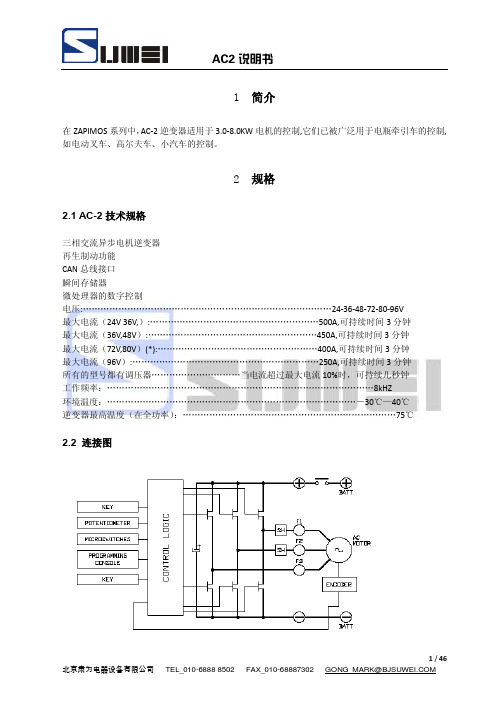
1 简介在ZAPIMOS系列中,AC-2逆变器适用于3.0-8.0KW电机的控制,它们已被广泛用于电瓶牵引车的控制,如电动叉车、高尔夫车、小汽车的控制。
2 规格2.1 AC-2技术规格三相交流异步电机逆变器再生制动功能CAN总线接口瞬间存储器微处理器的数字控制电压:…………………………………………………………………………24-36-48-72-80-96V最大电流(24V 36V,):…………………………………………………500A,可持续时间3分钟最大电流(36V,48V):…………………………………………………450A,可持续时间3分钟最大电流(72V,80V)(*):………………………………………………400A,可持续时间3分钟最大电流(96V):………………………………………………………250A,可持续时间3分钟所有的型号都有调压器…………………………当电流超过最大电流10%时,可持续几秒钟工作频率:………………………………………………………………………………8kHZ环境温度:…………………………………………………………………………-30℃—40℃逆变器最高温度(在全功率):………………………………………………………………75℃2.2 连接图3 输入装置的说明3.1 微动开关-微动开关接触电阻必需小于0.1欧姆;漏电电流必需小于100μA-在满负载的情况下,电锁开关触点之间的电压降幅要低于0.1V-当功能请求(例如运行请求)有效时,微动开关就向微处理器传送电压信号3.2 加速单元加速单元可以由一个电位器或者一个霍尔电路组成。
它由3线配置,电位器电源通过CNE#2接入。
电位器输出信号接入CPOT(CNE#),信号范围为0—10V。
电位器负端接入CNE#3.电位器的阻值范围应为0.5——10Ω负载范围一般是1.5-30mA,超出了这个范围就会出现故障。
电位器信号自动获得功能可使用手持单元实现,有用信号的最小和最大水平的调节可在两个方向上进行。
- 1、下载文档前请自行甄别文档内容的完整性,平台不提供额外的编辑、内容补充、找答案等附加服务。
- 2、"仅部分预览"的文档,不可在线预览部分如存在完整性等问题,可反馈申请退款(可完整预览的文档不适用该条件!)。
- 3、如文档侵犯您的权益,请联系客服反馈,我们会尽快为您处理(人工客服工作时间:9:00-18:30)。
目录1 简介2规范2.1D U ALAC2的技术规范52.2 DUALAC2&HP的技术规范 62.3 DUALAC2 POWER(加强型)的技术规范 72.4 DUALAC2&HP POWER(加强型)的技术规范 82。
5控制单元 8 2。
5。
1微动开关82。
5。
2 加速单元82.5.3 其他模拟控制单元 92.5。
4 速度反馈 92。
5.5 转向角传感器102.6保护特性112.7操作特性12 2.8 故障诊断13 2.9 热保护措施132.10 常规问题的解决与防范 13 2。
11 磁化与磁辐射 132。
12主接触器与应急开关143 安全与保护144、安装144。
1连接电缆 14 4.2 接触器 154.3熔断器15 4。
4 “DUALAC2" 与“DUALAC2”加强型的接线说明15 4。
5“DUALAC2" 与“DUALAC2&HP”加强型的接线说明 174.6编码器安装 194.7CANBUS连接器的结构 194.7.1单个DUALAC2 控制器 194.7.2“DUALAC2"作为CANBUS网络的终端模块 204.7.3“DUALAC2”作为循环模块接入CANBUS网络 204.8电源接线图 214.8.1“DUALAC2”214.8.2“DUALAC2加强型” 224.8.3“DUAL AC2&HP”234.8.4“DUALAC2&HP加强型" 244.9机械图 254.10“DUALAC2”与“DUALAC2加强型"标准接线图29 4。
11 “DUALAC2&HP”与“DUALAC2&HP加强型”标准接线图 305、利用手持单元的编程及调整315。
1使用手持单元调整315。
2手持单元及连接器接线的描述 31 5.3标准手持单元菜单的介绍 325.3.1“DUALAC2”与“DUALAC2加强型”菜单结构 32 5.3.1a 主菜单 325.3.1b 从菜单33 5。
3.2 “DUALAC2&HP"与“DUALAC2&HP加强型”菜单设置34 5.3.2a 主菜单 345。
3.2b 从菜单 355.4 功能设置355.4.1 “DUALAC2”与“DUALAC2加强型”-主控制部分 355。
4.2 “DUALAC2”与“DUALAC2加强型”—从控制部分375.4.3“DUALAC2&HP”与“DUALAC2&HP加强型”—主控制部分功能 38 5.4。
4 “DUALAC2&HP”与“DUALAC2&HP加强型”—从控制部分功能38 5.5参数调节40 5。
5。
1“DUALAC2”—主控制部分 405。
5。
2 “DUALAC2”—从控制部分 41 5。
5。
3“DUALAC2&HP”—主控制部分 41 5.5.4“DUALAC2&HP"—从控制部分 425.6 可编程的控制器的功能 46 5.6。
1功能设置(参见5.4)465.6.2 参数编程(参见5.5)465。
6。
3“DUALAC2&HP"与“DUALAC2&HP加强型”测试 465。
6.4“DUALAC2&HP”与“DUALAC2&HP加强型”测试475.6.5储存功能(存储数据)—仅适用于PC 控制 475.6。
6复制功能(下载参数用于其他控制)-仅适用于P C手持单元475。
6。
7 显示最后5次报警信息,连同小时计值,温度一起显示47 5。
6.8加速器范围整定 48 5。
6。
9 参见手持单元手册对于功能和参数的详细说明485。
7 AC牵引逆变器设置顺序485.8 测试功能描述48 5.8。
1 “DUALAC2"与“DUALAC2加强型”—主控制部分 495.8.2 “DUALAC2”与“DUALAC2加强型”—从控制部分505.8。
3“DUALAC2&HP”与“DUALAC2&HP加强型”-主控制部分 515.8。
4 “DUALAC2&HP"与“DUALAC2&HP加强型”—从控制部分526、其他功能546.1保存与复制功能 54 6。
2报警菜单描述54 6。
3 手持单元整定加速器操作过程557、“DUALAC2”与“DUALAC2&HP"故障诊断56 7。
1与牵引相关的错误编码 567。
2 手持单元显示的关于牵引相关的报警分析607.3 与泵斩波器相关的故障编码 64 7。
4 手持单元显示的关于油泵方面的报警分析 658、推荐使用部件659、定期维护67ﻩ=凡标注此记号的章节是与安全相关的内容签名表公司DEPT.设备执行经理工程执行部分出货管理员出版物编号:版本ﻬ1简介ZAPIMOS系列中的DUALAC2逆变器适合用于3—7KW一对电机控制。
DUAL AC2&Hp还可以控制直流泵电机,泵电机最高功率为15KW。
这些控制器可以被应用于以电瓶为动力的牵引和液压系统。
适用于电动车、电瓶汽车、牵引车等。
2 规范2.1 DUALAC2的技术规范配一对三相交流异步电机的逆变器再生制动功能CAN-BUS接口基于微处理器的数字控制(每个电机一个)电压………………………………………………………………………。
……24—36—48-72—80V最大电流(24V)…………………………..……………350A,对每个电机可连续工作3分钟最大电流(36V/48V)………………………….。
………275A,对每个电机可连续工作3分钟最大电流(72V/80V)………………………….。
………200A,对每个电机可连续工作2分钟工作频率………………………………………………………………………………………。
8kHz环境的温度范围………………………………………………………………………-30℃÷40℃逆变器最高温度(满负荷条件下)………………………………………………………..75℃ﻬ2.2 DUALAC2&HP的技术规范配一对三相交流异步电机的逆变器加配直流串励泵电机的斩波器再生制动功能CAN—BUS接口基于微型处理器的数字控制(每个交流电机一个)电压………………………………………………………………………。
……24-36—48—72-80V最大电流(24V)………………………….。
……………350A,对每个电机可连续工作3分钟最大电流(36V/48V)…………………………………275A,对每个电机可连续工作3分钟最大电流(72V/80V)…………………………。
………200A,对每个电机可连续工作2分钟斩波器最大电流(24V)…………………。
. ……………500A,对每个电机可连续工作2分钟斩波器最大电流(36V/48V)…………………。
. …… 420A,对每个电机可连续工作2分钟斩波器最大电流(72V/80V)………………….。
………300A,对每个电机可连续工作2分钟工作频率……………………………………………………………………………………….8kHz环境的温度范围………………………………………………………………………-30℃÷40℃逆变器最高温度(满负荷条件下)………………………………………………………。
.75℃斩波器框图2.3 DUALAC2 POWER(加强型)的技术规范配一对三相交流异步电机的逆变器再生制动功能CAN—BUS接口基于微型控制器的数字控制(每个电机一个)电压………………………………………………………………………….……24-36-48-72—80V 最大电流(24V)…………………………..…………450A,对每个电机可连续工作3分钟最大电流(36V/48V)………………………….. ………350A,对每个电机可连续工作3分钟最大电流(72V/80V)………………………….。
……… 275A,对每个电机可连续工作2分钟工作频率……………………………………………………………………………………….8kHz环境的温度范围………………………………………………………………………—30℃÷40℃逆变器最高温度(满负荷条件下)…………………………………………………………..75℃参见2—1节框图2.4 DUALAC2&HP POWER(加强型)的技术规范配一对三相交流异步电机的逆变器加配直流泵电机的斩波器再生制动功能CAN-BUS接口基于微型控制器的数字控制(每个交流电机一个)电压…………………………………………………………………………。
……24-36-48-72-80V最大电流(24V)………………………….。
……………450A,对每个电机可连续工作3分钟最大电流(36V/48V)………………………….. ………350A,对每个电机可连续工作3分钟最大电流(72V/80V)………………………….。
…… 275A,对每个电机可连续工作2分钟斩波器最大电流(24V)………………….. ……………500A,对每个电机可连续工作2分钟斩波器最大电流(36V/48V)…………………。
………420A,对每个电机可连续工作2分钟斩波器最大电流(72V/80V)………………….。
………300A,对每个电机可连续工作2分钟工作频率……………………………………………………………………………………….8kHz环境的温度范围………………………………………………………………………-30℃÷40℃逆变器最高温度(满负荷条件下)…………………………………………………………..75℃参见2—2节框图2.5 控制单元2.5.1 微动开关微动开关的接触电阻必须小于0.1Ω,漏电流必须小于100μA。
当满载时,电锁触点之间的电压必须小于0.1V。
当产生功能请求时(如运行请求),微动开关就会向微处理器发送一个电压信号。
2.5.2加速器加速器单元含有一个电位器或者一个霍尔元件。
它可以是一个三线的结构。
加速器(C21)信号的范围是0—10V。
电位器的阻值应该在0.5-10kΩ之间;负载范围一般的是1.5-30mA。
如果超出了这个范围就会出现故障。
PPOT提供加速器正极.他能够输出5V或10V。
输出电压的选择是通过逻辑卡的跳线来实现的。
NPOT提供加速器负极.他的输出被反馈到微处理器的A/D转换器来检测加速器电流的连续性(检测线路是否断开)。
自动编程程序可以用手持单元获得电位器信号。
这样就能够调节两个方向电位器最大和最小的有用信号的水平(PROGRAM VACC功能)。
当需要对与电位器相关联的机械性的不对称进行补偿时,这种方法是唯一的,尤其是关系到最小值的水平值时。
这个过程的顺序在手持单元操作说明书中有介绍。
以上两图给出了没有修正过的电位器输出电压和加速器(操纵杆)位于机械零点的对应关系图,MI和MA两点分别为前进和后退方向的闭合点;0表示加速器转动的机械零点。