天二插件金属氧化膜电阻MO系列选型规格书
台湾天二大阻值合金采样电阻TGL系列选型规格书
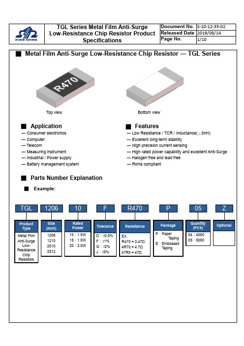
■Metal Film Anti-Surge Low-Resistance Chip Resistor — TGL SeriesTop view Bottom view■Application█Features— Consumer electronics — Low Resistance / TCR / Inductance(≦5nH)— Computer — Excellent long-term stability— Telecom — High precision current sensing— Measuring instrument — High rated power capability and excellent Anti-Surge — Industrial / Power supply — Halogen free and lead free— Battery management system — RoHs compliant■Parts Number Explanation■Example:Final Milestone DateCheckpointTGL1206F R470P05Size (Inch) 1206 1210 2010 2512ToleranceD:±0.5%F:±1%G:±2%J:±5%PackageP:PaperT apingE:EmbossedT apingQuantity(PCS)04:400005:5000ZOptionalProductTypeMetal Film Anti-SurgeLow-ResistanceChip ResistorsResistanceEX.R470=0.47Ω4R70=4.7Ω47R0=47Ω10RatedPower10:1.0W15:1.5W20:2.0W■Standard Electrical SpecificationsType RatedPowerat 70℃Max.RatedCurrentMax.OverloadCurrentT.C.R.(ppm/℃)Resistance RangeD(0.5%), F(1.0%), G(2.0%), J(5.0%)TGL1206 1W 3.16A 7.07A±50 100 mΩ ≦R ≦50 ΩTGL1210 1W 3.16A 7.07ATGL2010 1.5W 3.87A 8.66A±50 100 mΩ ≦R ≦50 ΩTGL2512 2W 4.47A 10.00A● For non-standard parts, please contact our sales dept.● Operating Temperature Range :−55℃〜+155℃.■Anti-Surge Ability:■Type Dimension■Construction Unit:mmTYPE L W H I1I2 TGL1206 3.10±0.10 1.60±0.10 0.55±0.10 0.40±0.20 0.45±0.20 TGL1210 3.10±0.10 2.50±0.15 0.55±0.10 0.50±0.20 0.50±0.20 TGL2010 5.00±0.20 2.50±0.15 0.55±0.10 0.60±0.25 0.60±0.25 TGL2512 6.30±0.20 3.20±0.20 0.55±0.10 0.65±0.25 0.65±0.25①Alumina Substrate ⑥Top Protective Overcoat②Resistive Layer ⑦Marking③Bottom Inner Electrode (Cu) ⑧Side Inner Electrode④Top Inner Electrode ⑨Barrier Layer (Ni)⑤Bottom Protective OvercoatWhite⑩Solder coating (Sn)■ Perfo r mance CharacteristicsPower Derating Curve ■The Operating Temperature Range: -55°C ~+155°C.Power rating or current rating is in the case based on continuous full-load at ambient temperature of 70℃. For operation at ambient temperature in excess of 70℃, the load should be derated in accordance with figure of derating Curve.■ Rated CurrentResistance Range: ≦ 1ΩRated Current: The resistor shall have a DC continuous working current or a AC (rms) continuous working current at commercial-line frequency and wave form corresponding to the power rating, as determined formula as following:I = Rated current (A) P= Rated Power (W) R= Resistance(Ω)■ Rated VoltageResistance Range: > 1ΩRated Voltage: The resistor shall have a DC continuous working voltage or a RMS AC continuous working voltage at commercial-line frequency and wave form corresponding to the power rating, as determined formula as following:V = Rated voltage (V)V = √P ×R P = Rated power (W)R = Nominal resistance (Ω)-5520406080100020406080100120140155℃Ambient Temperature (℃)Power Ratio(%)DERATING CURVE70160■Reliability Test and RequirementTest Item Test Method Procedure Requirements TemperatureCoefficient of Resistance(T.C.R) JIS C 5201-1clause 4.8TCR +125 ℃, 25 ℃is the reference temperatureRefer to StandardElectrical SpecificationsShort Time Overload JIS C 5201-1clause 4.135 times rated power for 5 seconds. ±(1.0%+0.001Ω)Insulation Resistance JIS C 5201-1clause 4.6100V for 1 minute. ≧10GΩDielectric Withstanding Voltage JIS-C5201-1clause 4.71206、1210、2010、2512 for 500 VAC 1minNo short or burned on theappearance.Core Body Strength JIS-C5201-1clause 4.15Central part pressurizing force:10N , 10 seconds No brokenSolderability JIS C 5201-1clause 4.17245±5°C for 3±0.5secs.>95% CoverageNo Visual damageResistance to Soldering Heat JIS-C5201-1clause 4.181. Molten solder, 260±5 °C,10±1 seconds immersion time2. IR reflow, refer to solder reflow temperature condition±(1.0%+0.001Ω)No Visual damageLeaching JIS-C5201-1clause 4.18260±5℃for 30 seconds.>95% CoverageNo Visual damageTemperature Cycling JIS C 5201-1clause 4.19-55℃to +155℃, 300 cycles±(1.0%+0.001Ω)No Visual damageLoad Life in Humidity JIS C 5201-1clause 4.2440±2℃, 90~95% R.H. , Rated power or Max. workingcurrent whichever is less for 1000 hrs with 1.5 hrs〝ON〞and 0.5 hr〝OFF〞.±(1.0%+0.001Ω)Load Life (Endurance) JIS C 5201-1clause 4.2570±2℃, Rated power, or Max. working current whichever isless for 1000 hrs with 1.5 hrs〝ON〞and 0.5 hr〝OFF〞.±(1.0%+0.001Ω)High Temperature Exposure JIS C 5201-1clause 4.25155±5℃for 1000 +48/-0 hours. ±(1.0%+0.001Ω)Resistance to Solvent JIS C 5201-1clause 4.29The tested resistor be immersed into isopropyl alcohol of20~25℃for 60 secs.Then the resistor is left in the room for 48 hrs.±(1.0%+0.001Ω)No Visual damageTerminal Strength JIS-C5201-1clause 4.32Pressurizing force for 10 seconds1206 and above:17.7NNo brokenTerminal Bending Strength JIS C 5201-1clause 4.33Bending once for 5 secondsD:1206、1210 = 3mm2010、2512 = 2mm±(1.0%+0.001Ω)No Visual damage● Temperature Coefficient of Resistance test to - 55 ℃is available on request■MarkingSolder reflow Temperature condition■Appendix For SMD Chip ResistorSIZE A ΦB ΦC■Packaging Information■Tapping SpecificationUnit: mm Packaging Type A B W E F G H T ΦD PPaper Type1206 1.90±0.2 3.05±0.28.0±0.2 1.75±0.1 3.5±0.05 4.0±0.1 2.0±0.050.75±0.1 4.0±0.11210 2.85±0.2 3.05±0.28.0±0.2 1.75±0.1 3.5±0.05 4.0±0.1 2.0±0.050.75±0.1 4.0±0.1■Embossed DimensionUnit: mm Packaging Type A B W E F G H T ΦDΦD1T1 PEmbossedType 2010 2.80±0.25.60±0.212±0.1 1.75±0.15.5±0.05 4.0±0.1 2.0±0.050.23±0.1 1.50±0.10.85±0.15 4.0±0.1 2512 3.40±0.2 6.70±0.212±0.1 1.75±0.15.5±0.05 4.0±0.1 2.0±0.050.23±0.1 1.50±0.10.85±0.15 4.0±0.1PaperCarrier■ Packing Material Data / Storage Data■ Front & Back Lead Dimension■ Top Adhesive Peel Off Strength :10~70g■ PackageInner Box Size Reel Size H(mm) 1 13 2 24 3 36 5 60 10113■ Storage Data :Storage time at the environment temp: 25±5℃& humidity: 60±20% is valid for one year from the date of delivery. External Box SizeContain (Kpcs) Length (mm)Width (mm)Width (mm)25K 180 180 60 50K 180 180 110 150K 430 200 200 300K400400200。
金属氧化膜电阻规格书

将供试电阻器本体固定,于导线末端负重 0.5Kg,使用电阻器本体与导线成 90°弯曲,然后灰复为水
受控文件
禁止复印
金属氧化膜电阻规格书
文件编号 ZL- QW- 002 版 本 A 发行日期 2008-3-28 页 次 9~7
平状,此操作一次约 5 秒种为 1Cycle,依上述方法共试 2Cycles 试验后导线不断裂或松弛等现象。
100KΩ以下:
±(5%+0.05Ω)
100KΩ(含)以上: ±(10%+0.05Ω)
±(1%+0.05Ω)
±(1%+0.05Ω)
±(1%+0.05Ω
±350 PPM/℃
不燃烧、不熔化
400V 250V
试验方法
5.7.8 如图二 5.7.2
5.7.3
5.7.4 5.7.5 5.7.6 5.7.12 5.7.7 5.7.9
文件编号 ZL- QW- 002 版 本 A 发行日期 2008-3-28 页 次 9~5
G
表二 Size
0207 0309 0309 0512 0512 0616 0616
(图五)
成型 Type PU PUG PFK PUG PFK PUG PFK
P
10±1 12.5±1 7.5±1 15±1 10±2 20±1 10±2
3.6 绝缘电压:在连续工作条件下,在电阻器的各个引出端与任何导电安装面之间可以施加的最大峰值电
压。
3.7 电阻温度系数:两个规定温度之间的阻值相对变化除以产生这个变化的温度之差。
4、职责
本规格书执行标准 GB/T5729—2003/IEC60115-1:2001
5、程序内容
金属膜电阻规格书

1Ω-10MΩ
MF5W / 5WS
500V
1000V
1000V
1Ω-10MΩ
4 – 1.POWER RATING
Power rating is defined as maximum power rating continuously applied under ambient temperature at 70℃.when the ambient temperature exceeds 70℃ ,use chart 1.
Resistance variation shall be within ±(0.5% + 0.05ohm) also there Shall be on mechanical breakage
JIS-C-5202 5.8 Apply AC voltage 4 times the rated voltage for 1 second and rest for 25 seconds and Repeat this cycle for 10000±200times leave resistor 30 minutes at room temperature after test and measure Maximum voltage for intermittent Overload.0.50W – 700V(AC) Pull test apply 2.5kg force to the lead in the direction of lead axisfor30±5 seconds.
TEL:0769-85325266 FAX:0769-85325766
東莞超翔電子有限公司 編號
版本
金屬膜電阻器
METAL FILM RESISTORS
金属膜电阻型号及选用方法

金属膜电阻
详细信息:
详细信息:
详细信息:
详细信息:
金属膜电阻器就是以特种金属或合金作电阻材料,用真空蒸发或溅射的方法,在陶瓷或玻璃基本上形成电阻膜层的电阻器。
这类电阻器一般采用真空蒸发工艺制得,即在真空中加热合金,合金蒸发,使瓷棒表面形成一层导电金属膜。
刻槽和改变金属膜厚度可以控制阻值。
它的耐热性、噪声电势、温度系数、电压系数等电性能比碳膜电阻器优良。
金属膜电阻器的制造工艺比较灵活,不仅可以调整它的材料成分和膜层厚度,也可通过刻槽调整阻值,因而可以制成性能良好,阻值范围较宽的电阻器。
这种电阻和碳膜电阻相比,体积小、噪声低、稳定性好,但成本较高,常常作为精密和高稳定性的电阻器而广泛应用,同时也通用于各种无线电电子设备中。
金属氧化膜固定电阻器特性、性能技术规格书
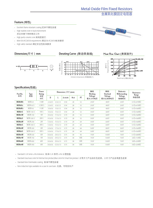
Feature (特性)•Excellent flame retardant coating 优异不燃性涂装 •High stability even in bad environment 恶劣环境下同样稳定工作•High purity ceramic core 高纯度瓷芯•Meet EIA-RC2655A requirements 满足EIA-RC2655A 标准要求•High safety standard 满足安全性标准要求Dimension(尺寸)mm Derating Curve (降功率曲线)Metal Oxide Film Fixed Resistors金属氧化膜固定电阻器Heat Rise Chart (表面温升)P e r c e n t r a t e d l o a d (%)Rated load (负载比率) (%)T e m p e r a t u r e r i s e (°C )Ambient temperature (环境温度)(°C)负载比率(%)温升(°C )Specification(性能)Part No.料号Type 类型Power Rating 功率70°C Dimension (尺寸)(mm)MAX.Working Voltage 最大工作电压MAX.Overlaod Voltage 最大过负荷电压Dielectric Withstanding Voltage 绝缘耐压Resistance Range 阻值范围D L d ±0.05H±3PT MOR0W4MOR-251/4W 2.2±0.5 6.5±1.00.542852250V 400V 250V 0.1Ω~470KΩMOR0S2MOR-50-S 1/2W-S 2.2±0.5 6.5±1.00.542852250V 400V 250V 0.1Ω~470KΩMOR0W2MOR-501/2W 3.0±0.69.5±1.00.542852250V 400V 250V 0.1Ω~560KΩMOR01S MOR-100-S 1W-S 3.5±0.69.5±1.00.542852350V 600V 350V 0.1Ω~560KΩMOR01W MOR-1001W 4.5±0.611.5±1.00.702852350V 600V 350V 0.1Ω~560KΩMOR02S MOR-200-S 2W-S 4.5±0.611.5±1.00.702852350V 600V 350V 0.1Ω~560KΩMOR02W MOR-2002W 5.0±0.615.5±1.00.702864350V 600V 350V 0.1Ω~560KΩMOR03S MOR-300-S 3W-S 5.0±0.615.5±1.00.702864350V 600V 350V 0.1Ω~560KΩMOR03W MOR-3003W 6.0±0.617.5±1.00.752864500V 800V 500V 0.1Ω~560KΩMOR05S MOR-500-S 5W-S 6.0±0.617.5±1.00.752864500V 800V 500V 0.1Ω~560KΩMOR05W MOR-5005W 8.0±0.624.5±1.00.753890750V 1000V 750V 0.1Ω~680KΩMOR07W MOR-7007W 8.0±0.629.5±1.00.7538B/B 750V 1000V 750V 20Ω~150KΩMOR08W MOR-8008W 8.0±0.639.5±1.00.7538B/B 750V 1000V 750V 30Ω~200KΩMOR09WMOR-9009W8.0±0.652.5±1.00.7538B/B750V1000V750V50Ω~200KΩ•Standard E-24 Series ±5% tolerance 标准E-24系列±5% 公差阻值•Standard Gray base color for Normal Size product,Blue color for Small Size product 正常尺寸产品涂灰色底漆,小尺寸产品涂海蓝色底漆•Standard Non-Flammable coating 标准不燃性涂装•Non-Inductive type available on a case to case basis 无感,可特别生产Performance Specification(性能)Metal Oxide Film Fixed Resistors金属氧化膜固定电阻器Temperature coefficient 温度系数1/4W,1/2WS: ≤ 100K Ω:±350PPM/°C ; 100KΩ<R≤470KΩ:0~-700PPM/°C 1/2W,1WS: ≤ 120K Ω:±350PPM/°C ; 120KΩ<R≤560KΩ:0~-700PPM/°C1W,2W,2WS,3W,3WS,5WS: ≤ 150K Ω:±350PPM/°C ; 150KΩ<R≤560KΩ:0~-700PPM/°C 5W,: ≤ 180K Ω:±350PPM/°C ; 180KΩ<R≤680KΩ:0~-700PPM/°C 7W,8W ,9W: ±350PPM/°CShort-time Overload短时间过负荷Normal size(正常尺寸),ΔR/R ≤ ±(1%+0.05 Ω), with no evidence of mechanical damage (无可见机械损伤) Small size(小尺寸),ΔR/R ≤ ±(2%+0.05 Ω), with no evidence of mechanical damage (无可见机械损伤)Dielectric withstanding voltage绝缘耐压No evidence of flashover,mechanical damage,arcing or insulation breakdown ( 无击穿、飞弧及可见机械损伤)Pulse Overload 脉冲过负荷Normal size(正常尺寸),ΔR/R ≤ ±(2%+0.05 Ω), with no evidence of mechanical damage (无可见机械损伤) Small size(小尺寸),ΔR/R ≤ ±(5%+0.05 Ω), with no evidence of mechanical damage (无可见机械损伤)Terminal strength 端子强度No evidence of mechanical damage ( 无可见机械损伤)Soldering heat 耐焊接热ΔR/R ≤ ±(1%+0.05 Ω), with no evidence of mechanical damage (无可见机械损伤)Solderability 可焊性Min.95% coverage (最少95%覆盖率)Resistance to solvent 耐熔剂No deterioration of protective coating and markings (包封层,色码完整)Temperature cycling 温度循环ΔR/R ≤ ±(2%+0.05 Ω)with no evidence of mechanical damage (无可见机械损伤)Humidity ( Steady State )恒定湿热ΔR/R ≤ ±(2%+0.05 Ω)with no evidence of mechanical damage (无可见机械损伤)Load life in humidity湿度寿命< 100kΩ : ±(5%+0.05Ω)MAX ,≥100kΩ :±(10%+0.05Ω) MAX;Load life负载寿命< 100kΩ : ±(5%+0.05Ω)MAX ,≥100kΩ :±(10%+0.05Ω) MAX;Flame retardant阻燃Resistor insulation is self-extinguishing within 10 seconds after externally applied flame is removed (火焰移开后10秒内,电阻自动绝燃,无可见火焰)。
插件电阻规格表

插件电阻规格表1. 引言插件电阻是电子电路中常见的被动元件之一,用于调节电路中的电阻值。
在电子产品的设计和制造中,插件电阻规格表是非常重要的参考文档。
本文将介绍插件电阻规格表的内容和使用方法。
2. 插件电阻规格表的结构插件电阻规格表通常包含以下几个方面的信息:2.1 电阻值范围插件电阻的电阻值通常以欧姆(Ω)为单位表示,规格表中会列出电阻值的范围。
这个范围可以从几个欧姆到几百万欧姆不等,根据实际需要选择合适的电阻值。
2.2 容差插件电阻的容差是指实际电阻值与标称电阻值之间的允许误差范围。
容差通常以百分比表示,规格表中会列出容差的最大值。
较常见的容差包括1%、5%和10%等。
2.3 功率插件电阻的功率是指电阻器能够承受的最大功率。
功率通常以瓦特(W)为单位表示,规格表中会列出功率的数值。
常见的功率有1/8W、1/4W和1/2W等。
2.4 封装尺寸插件电阻的封装尺寸是指电阻器的外形尺寸,包括长度、宽度和高度等。
规格表中会列出电阻器的尺寸,以便在设计电路时能够合理安排元件的布局。
2.5 温度系数插件电阻的温度系数是指电阻值随温度变化的程度。
温度系数通常以每摄氏度(ppm/°C)表示,规格表中会列出温度系数的数值。
常见的温度系数有50ppm/°C和100ppm/°C等。
3. 使用插件电阻规格表使用插件电阻规格表需要注意以下几个方面:3.1 选择合适的电阻值根据电路设计的需要,选择合适的电阻值范围。
如果需要精确的电阻值,可以选择容差较小的电阻器。
3.2 确定合适的容差根据电路设计的要求,确定合适的容差范围。
容差较小的电阻器价格较高,容差较大的电阻器价格较低。
3.3 考虑功率要求根据电路中电阻器的功率消耗,选择合适的功率。
功率较大的电阻器可以承受较高的功率,但体积较大。
3.4 确认封装尺寸根据电路中的布局需求,确认插件电阻的封装尺寸。
尺寸较小的电阻器可以节省空间,但功率承受能力较低。
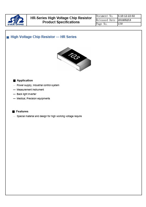
台湾天二高压芯片电阻器HR系列选型手册
Test Item
Temperature Coefficient of Resistance (T.C.R) Short Time
Overload
IR Reflow
Test Method
Procedure
JIS C 5201-1 clause 4.8
-55℃ or +155℃, 25℃ is the reference temperature.
T.C.R (ppm/℃)
±100 ±100
Resistance (Ω)
J : ±5%
F : ±1%
100K ~ 10M
HR-Series High Voltage Chip Resistor Product Specifications
Document No. S-10-12-22-02
Released Date 2019/02/13
13” 40K/50K Reel 2.0±0.5 13.5±1.0
7”
5K/Reel
2.0±0.5 13.5±1.0
10” 10K/Reel 2.0±0.5 13.5±1.0
13” 20K/Reel 2.0±0.5 13.5±1.0
7”
4K/Reel
2.0±0.5 13.5±1.0
ψC 21±1.0 21±1.0 21±1.0 21±1.0 21±1.0 21±1.0
H 0.30 ± 0.05 0.40 ± 0.10 0.50 ± 0.15 0.55 ± 0.15 0.55 ± 0.15 0.55 ± 0.10 0.55 ± 0.10
l1 0.15 ± 0.10 0.30 ± 0.20 0.30 ± 0.15 0.40 ± 0.20 0.50 ± 0.20 0.60 ± 0.20 0.60 ± 0.20
MAKO中文金属膜(金属氧化膜)规格书

金屬膜電阻器
Page 2 of 10
DATE: 2007-11-12
圖一、降功耗曲線
FIG 、1 DERAING CURVE
-55
周圍溫度
圖一:電力減輕曲線
依公式 E=√P*R 求出連續使用額定電壓,如額定電壓超出最高使用電壓,則以最高使用電壓為連續
絕緣抵抗 耐電壓
斷續過負載
端子強度 拉力強度 長時間負荷壽命
規格值 ±100PPM/℃ ±(0.75% + 0.05Ω)以內 1000MΩ以上 塗裝不可損壞絕緣不可破壞
±(2% + 0.05Ω)以內
端子外端沒有鬆動 ± (1.5%+0.05Ω)
試驗方法
按 JIS-C-5202 5.2 條件: 溫度範圍-55℃~+155℃
金屬膜電阻器
Page 1 of 10
DATE: 2007-11-12
金属膜(金属氧化膜)规格書
(APPROVAL SHEET)
1. 適用範圍:
金属膜(金属氧化膜)固定電阻器。
2. 形名
依據其種類,額定電力,端子形狀,特性,公稱電阻值及容許誤差等分別注明 例:
MF 種類
W 額定電力
P 端子形狀
B 特性
2-5 公稱電阻值
Ω.KΩ為單位,依據 JIS-C6402 為選用原則.(E-24Series)
2-6 電阻值及容許差
在室溫中依電橋測量,應在指定電阻之容許差以內. F±1% G±2% J±5% K±10%
3.額定功率
額定電力是周圍溫度 70℃以下,可連續使用之負載電力最大值數,且應使機械性 能與電氣性能
p±0.5
- 1、下载文档前请自行甄别文档内容的完整性,平台不提供额外的编辑、内容补充、找答案等附加服务。
- 2、"仅部分预览"的文档,不可在线预览部分如存在完整性等问题,可反馈申请退款(可完整预览的文档不适用该条件!)。
- 3、如文档侵犯您的权益,请联系客服反馈,我们会尽快为您处理(人工客服工作时间:9:00-18:30)。
■ Power Graph (℃)
70℃
■ Hot-Spot Temperature (%)
MO 3B 5B/ MO 7WS MO 2WS/ MO 3WS MO 2B / MO 1WS MO 1B MO 1/2B MO 1/4B
SURFACE TEMP. RISE ( )
Rated Load(%)
Ambient Temperature (℃)
★ Miniature Series: Flameproof Coating , Pink color
■ Electrical Characteristics
Power rating at 70℃ 1/4W 1/2WS 1/2W 1WS
Operating Temp. Range
Max. Working Voltage 200V 250V 250V 300V
No deterioration of coatings and markings
Terminal Strength
Direct load for 10 sec. In the direction off the terminal leads. Tensile:≧2.5kg
★ Rated continuous Working Voltage (RCWV) = POWER.RATING.* RESISTANCE.VALUE
H
28±2.0 26±2.0 35±2.0 32±2.0 35±2.0 35±2.0
Unit: mm
d
Comment
0.55±0.03 0.65±0.03 0.76±0.03 0.76±0.03 0.78±0.03 0.78±0.03
★ Standard Series: Flameproof Coating , Grey color
JIS-C5202 5.6
In V-Block
>10000MΩ
Load Life Load Life in Humidity
Solder Ability
JIS-C5202 7.10 70℃ at RCWV for 1000hrs.(1.5hrs. on,0.5hrs.off)
JIS-C5202 7.9 40±2℃ 90~95%.5hrs.off)
1W
2WS
2W 3WS
-55℃ to +155℃ 350V 350V 350V 400V
600V 600V 600V 700V
500V 500V 500V 600V
1Ω~510KΩ, E24 series
3W 5WS 5W 7WS
400V 750V 750V 750V 700V 1000V 1000V 1000V 600V 1000V 1000V 1000V
JIS-C5202 5.7
In V-Block for 60 seconds
By Type
Pulse Overload
JIS-C5202 5.8 4 times RCWV for 10000cycles(1sec.on,25secs.off)
±(1%+0.05Ω)
Insulation Resistance
深圳捷比信--高品质精密元件供应商
www.jepsun.com
■ Parts Number Explanation ■ Example:
MO 1/4W
F
Product Type
Size (Inch)
1/4W 1/2WS 1/2W
1W 1WS 2W 2WS 3W 5W 5WS 7WS
Resistor Tolerance
■ Dimension
TYPE / Rated Power at 70℃
Standard
Miniature
1/4W
1/2WS
1/2W
1WS
1W
2WS
2W
3WS
3W
5WS
5W
7WS
L
6.3±0.5 9.0±0.5 11.5±1.0 15.5±1.0 17.5±1.0 24.5±1.0
D
2.3±0.3 3.2±0.5 4.5±0.5 5.0±0.5 6.5±0.5 8.5±0.5
JIS-C5202 6.5
260±5℃ for 2±0.5 seconds
±(1.5%+0.05Ω) ±(1.5%+0.05Ω) 95% min. coverage
Resistance to Solvent
JIS-C5202 6.9 Trichroethane for 1 min. with ultrasonic
深圳捷比信--高品质精密元件供应商
www.jepsun.com
■ Metal Oxide Flame-Proof Resistor — MO Series
■ Features
─ Low cost, prompt delivery ─ High power-to-size ratio for significant space savings ─ Excellent long-time stability ─ Complete flameproof construction UL–1412 ─ High surge/overload capability ─ Wide resistance range: 0.1Ω~1mΩ ─ Controlled temperature coefficient ─ Resistance standard tolerance:±5%(consult factory for±2% ±1%) ─ Coating and marking resist trichorethelyne, freon, and other cleaning agents ─ Non-inductive design, resistance range: 0.1Ω~100Ω
Requirements ±(0.25%+0.05Ω)
Temperature Coefficient Resistance (T.C.R.)
Resistance value at room Temperature and room Temperature+100℃
By Type
Dielectric Withstanding Voltage
Max. Overload Voltage 350V 400V 400V 500V
Dielectric Withstanding Voltage
Resistance Range (±1%.±2%.±5%)
350V
350V
350V
400V
● For non-standard parts, please contact our sales dept.
℃ Applied Load % of RCWV
深圳捷比信--高品质精密元件供应商
www.jepsun.com
■ Temperature Coefficient (T.C.R.)
TYPE 1/4W, 1/2WS, 1/2W, 1WS 1W, 2WS, 2W, 3WS, 3W, 5W, 5WS, 7WS
F:±1% G:±2% J:±5%
10R
Resistors Value
P
Package P、W:Tape D:Bulk
05
Quantity 01 : 1000PCS 05 : 5000PCS
Max. Value of Temp. Coefficient ppm/℃ ±300 ppm
■ Environmental Characteristics
Performance test
Test Method
Short time Overload
JIS-C-5202 5.5 2.5 times RCWV for 5 seconds