气体加工工程数据手册
塑料管道气体操作和维护手册说明书

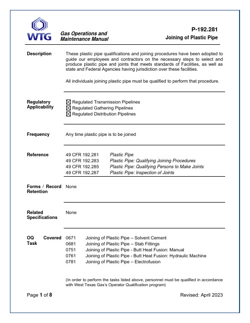
DescriptionJoining of Plastic Pipe Maintenance ManualProcedure StepsDesign Specifications:1. Only new polyethylene plastic pipe will be used in West Texas Gas’s facilities for NewConstruction. It must be qualified for natural gas use by the manufacturer accordance with listed specifications, free from visible defects and is, resistant to gas, chemicals, and its environment.2. The pipe must be manufactured and marked to the standard in accordance to ASTM D 2513and marked every two feet and legible at time of installation to indicate the following:a. Sizeb. Materialc. Manufacturerd. Pressure Ratinge. Temperature Ratingf. Type, grade, or model.3. The design pressure may not exceed 100 psig for plastic pipe used in distribution systems andat class 3 and 4 locations.4. Plastic pipe may not be used where operating temperatures are below -20 degrees F or above100 degrees F.5. The wall thickness for thermoplastic pipe may not be less than 0.062 inches. For reinforcedthermosetting plastic pipe, the minimum wall thickness must meet the following table.Nominal Size Wall Thickness2” 0.060”3” 0.060”4” 0.070”6” 0.100”6. Design pressure for thermoplastic, fittings must conform to ASTM D 2513.When joining plastic pipe with a solvent cement, adhesive, or heat fusion, do not disturb the joint until it has properly set. Threaded or miter joints are not to be used on plastic pipe. Used plastic pipe should not be utilized for gas handling processes.Types of Joints:1. Solvent Cement JointsJoining of Plastic Pipe Maintenance Manual2. Heat-fusion Joints3. Mechanical Joints:Qualifying Joining Procedures1. Plastic pipe will not be joined by a threaded joint or by a miter joint.2. A plastic pipe joint that is joined by solvent cement, adhesive or heat fusion may not bedisturbed until it has properly set.3. Prior to using tools/equipment used in joining plastic pipe, the operator must ensure the tool iswithin calibration dates and being used within the manufacturer’s recommended practice.4. All joints must be made following written procedures that have been proven by testing per thefollowing testing requirements to produce strong gastight joints. These procedures must be qualified according to the following:a) Heat fusion and solvent cement:Before a procedure that has been written can be used to make these joints, it must be qualified by subjecting a specimen joint made using the procedure to the following tests:i. Burst test requirements of –∙Paragraph 6.6, or 6.7 of ASTM D2513 (thermoplastic pipe). WTG will not install thermosetting plastic pipe.∙Paragraph 9.1, 9.2, 9.3, or 9.4 of ASTM Designation F1055 (electrofusion fittings for polyethylene pipe and tubing)ii. If the procedure is intended for lateral pipe connections, a specimen joint made from pipe sections joined at right angles according to the procedure will be subjected to aforce on the lateral pipe until failure occurs in the specimen. Failure must initiateoutside the joint area for the procedure to qualify.iii. If the procedure is intended for non-lateral pipe connections, follow the tensile test requirements of ASTM D638, except that the test may be conducted at ambienttemperature and humidity. If the specimen elongates no less than 25% or failureinitiates outside of the joint area, the procedure may be used.b) Mechanical joints - Before a procedure that has been written can be used to makemechanical plastic pipe joints that are designed to withstand tensile forces, the procedure must be qualified by subjecting 5 specimen joints made according to the procedure to the following tensile test:i) The apparatus for the test must be specified in ASTM D638 (except for conditioning).ii) Ensure that the specimen is long enough that the distance between the grips or the apparatus and the end of the stiffener does not affect the joint strength.iii) Test at a speed of 0.20 inches per minute, plus or minus 25%.iv) Specimens less than 4 inches in diameter are qualified if the pipe yields to an elongation of no less than 25% or failure initiates outside of the joint area.Joining of Plastic Pipe Maintenance Manualv) Pipe specimens 4 inches in diameter and larger shall be pulled until the pipe is subjected to a tensile stress equal to or greater than the maximum thermal stress thatwould be produced by a temperature change of 100 degrees F or until the pipe ispulled from the fitting. If the pipe pulls from the fitting, the lowest value of the five testresults or the manufacturer’s rating, whichever is lower must be used in the designcalculations for stress.vi) Each specimen that fails at the grips must be retested using new pipe.vii) Results obtained pertain only to the specific outside diameter, and material of the pipe tested, except that testing of a heavier wall pipe may be used to qualify pipe of thesame material with a lesser wall thickness.c) A copy of each written procedure used for joining pipes must be available to the individualsmaking and inspecting the joints.d) WTG will not install pipe or fittings manufactured prior to July 1, 1980.Qualifying Individuals to Make JointsAll individuals making plastic pipe joints must be qualified under the applicable procedures by appropriate training or experience in the use of the procedure and by making a specimen joint from pipe sections joined according to the procedures that passed inspection as described below: 1. The joint must be visually examined during and after assembly and found to have the sameappearance as a joint or photographs of a joint that is acceptable under the procedure; and2. In the case of heat fusion, solvent, cement or adhesive joints:a) Tested under any of the test methods listed above applicable to the type of joint andmaterial being tested; orb) Cut into at least 3 longitudinal straps, each of which is:i) Visually examined by the District Manager and found not to contain voids ordiscontinuities on the cut surfaces of the joint area; andii) Deformed by bending 180 degrees, and if failure occurs, it must not initiate in the joint area3. All personnel qualification records must be maintained for a minimum of five years followingconstruction.NOTE: A person must be re-qualified under an applicable procedure once each calendar year at intervals not exceeding 15 months, or after any production joint is found unacceptable by testing under §192.513.Qualification of Plastic Pipe JoinersThe District/Division Manager shall assure that all employees joining pipe have been qualified in accordance with procedures published by Energy Worldnet (EWN) The District Manager and local supervision will ensure all persons joining pipe will be qualified according to these procedures, and a record or qualified persons kept on file. Butt fusion joints will be visually inspected and tested inJoining of Plastic Pipe Maintenance Manualaccordance to ASTM F 2620 or an alternative written plan approved by WTG Vice-President of Operations.Joining Plastic PipeNote: All materials and joints must comply with ASTM D 2513 requirements.Each solvent cement joint on plastic pipe must comply with the following:1. The mating surfaces of the joint must be clean, dry, and free of materials, which might bedetrimental to the joint.2. Use only primer with ASTM F 656 designation and solvent cement with ASTM D 2564designation.3. Use only PVC fittings marked ASTM D 2466 or ASTM D 2513.4. Use only PVC pipe marked ASTM D 2513.5. The joint may not be heated to accelerate the setting of the cement.Each heat-fusion joint on plastic pipe must comply with the following:1. Each heat fusion tool must be maintained and calibrated in accordance with themanufacturer’s recommended practices.2. A butt heat-fusion must be joined by a device that holds the heater element square to theends of the piping, compresses the heated ends together, and holds the pipe in proper alignment while the plastic hardens.3. Heat may not be applied with a torch or open flame.Solvent Cement Joints1. Solvent Cement for PVC pipe and fittingsa) Primeri. Primer is a special cleaner that will cut through and clean the dense surfaceof PVC pipe. Primer must be applied liberally and with a scrubbing motion.b) Solvent Cementi. Solvent Cement must be free flowing, contain no lumps, dissolved particlesor any foreign matter that would affect the joint strength.ii. Solvent Cement must not show gelatin, stratification, oriii. Separation that cannot be removed by stirring. Keep container closed when not in use.2. Safe Handling of Primer and Solvent Cementa) Liquid solvent and their vapors contained in plastic pipe cement andprimers are highly flammable. The solvents if improperly handled can causepersonal injury. Follow these precautions when using primer and solvent cement.i. Avoid prolonged breathing of solvent vapors when in closed areas.ii. Keep solvent primers and solvent cement away from all sources of heat, sparks and open flame.Joining of Plastic Pipe Maintenance Manualiii. Container should be tightly closed except when the contents are being used.iv. Use eye protection when using these liquids. In case of eye contact flush with plenty of water for 15 minutes and seek medical attention.v. Wear protective gloves to protect hands when applying cement or primer.vi. Use soap and water to wash skin in case of contamination.3. Joining Proceduresa) Pipe ends to be joined must be cut square. Use a fine tooth saw and a miter box ifnecessary.b) Chamfer and deburr the cut ends. Failure to chamfer (bevel edge) the ends of thepipe will result in the softened plastic being deformed as the pipe is inserted into thesocket. This results in a leaking joint.c) All surfaces to be joined must be clean and free of moisture. Use clean dry cloth toclean and dry mating surfaces.d) Measure and mark the socket depth of the fitting on the outside of the pipe. Use asoft point marker so as not to scratch the pipe surface.e) Apply primer and cements with a natural bristle brush. Use a ½” brush for smallpipe. For pipe sizes larger than 2” use a brush width that is equal to ½ the pipediameter. Keep the brush immersed in the primer or cement between applications.Keep cement container tightly closed when not being used. Discard the cement atthe first sign of gelling.f) PVC solvent cement is fast drying and must be applied as quickly as possible. Itmay be necessary for two employees to perform this operation on larger diameterpipe, or when the temperature of the fittings and pipe is at or above 100 degrees F.g) Use a scrubbing motion to apply primer to inside of the socket surface to ensurepenetration. Repeat application may be necessary to soften the surfaces to bejoined. Next, soften the surface of the pipe end up to the previously marked socketdepth. Do not soften any pipe surface that will not be covered by the socket. Applysolvent cement to the pipe end and a light coat of cement to the inside surface ofthe socket. Avoid excess cement in the socket. Time is important at this stage ofthe joining process. Apply a second coat of cement to the pipe end.h) Assembly of joint – Immediately after applying the last coat of cement topipe insert the pipe into the socket. Turn the pipe ¼ turn during assembly (but notafter the pipe is fully bottomed) to distribute the cement evenly. Insert pipe with asteady even motion.i) Assembly must be completed within 20 seconds after the last application of cement.On larger size pipe two employees or mechanical forcing equipment may beneeded to hold the pipe in place for one minute after assembly. Do not disturb orapply any force to joints. The joint can be destroyed by early rough handling.j) After assembly – Wipe excess cement from the pipe at the end of the socket fitting.A properly made joint will show a bead of cement around its entire perimeter. Anygaps indicate a defective joint that must be cut out and replaced.k) Cure Time - Handle assembled joints carefully until the cement has completed the cure period. See the following table for cure times.1. 30 minutes minimum at 60 to 100 degree F2. 1 hour min. at 40 to 60 degree F3. 2 hour min. at 20 to 40 degree FJoining of Plastic Pipe Maintenance Manual4. 4 hour min. at 0 to 20 degree F4. Testing PVC Jointsa) Pressure test on PVC piping and jointing will be conducted the same as testingprocedures of plastic as outline in P-192.501.5. Other Requirementsa) Tracer wires, tapes, or cable present on the system for locating purposes must berepaired if damaged after completion of all joining and before backfilling.Heat Fusion – Butt JointsGeneralThis procedure has been qualified according to procedures published by the pipe manufacturer and as outlined in the Minimal Federal Safety standards for Pipelines Transporting Natural Gas. ApplicationThis procedure can be used for all systems and class locations that operate less than 100 psi.Procedures1. Process: Heat Fusion2. Material: Polyethylene3. Diameter: ¾” thru 6”4. Joint Type: Butt Fusion5. Joining:i. Proper precautions need to be taken in a gaseous atmosphere to prevent anaccidental ignition.ii. Clean each pipe with clean cloth. Do not use synthetic or treated cloths.iii. Square each end of pipe to be fused.iv. Check line-up of pipe ends. Adjust for high or low.v. Check heater temperature – should be 400-450 degrees F.vi. Insert heater plate between pipe ends and bring ends firmly into contact with plate, but do not apply pressure, achieve a melt bead of 1/16” to 1/8”depending on pipe size.vii. Remove heater plate and bring melted ends together. Apply only enough pressure to obtain a double roll back bead.viii. Allow the joint to cool at least 30 seconds before removing pressureHeat Fusion – ElectrofusionAll electrofusion joining processes will be made using the equipment and techniques that are recommended by the fittings manufacturer.Joining of Plastic Pipe Maintenance ManualRepair of Plastic PipeEach imperfection or dame, such as crushes, gouges or grooves that would impair the serviceability of plastic pipe must be repaired by patching saddle or removed.Inspection of JointsAll individuals inspecting joints must be qualified by appropriate training or experience in evaluating the acceptability of plastic pipe joints made under the applicable joining procedure and approved by the District Manager after proper training on visual examination of joints.。
燃气技术学习手册(工程1册).doc

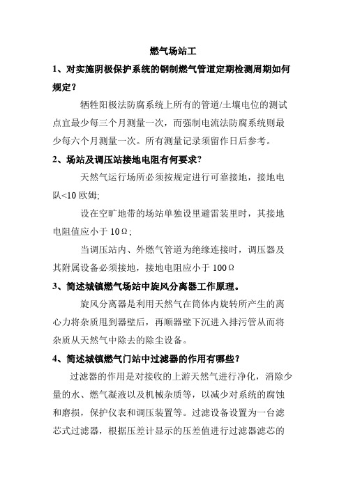
燃气场站工1、对实施阴极保护系统的钢制燃气管道定期检测周期如何规定?牺牲阳极法防腐系统上所有的管道/土壤电位的测试点宜最少每三个月测量一次,而强制电流法防腐系统则最少每六个月测量一次。
所有测量记录须留作日后参考。
2、场站及调压站接地电阻有何要求?天然气运行场所必须按规定进行可靠接地,接地电队<10欧姆;设在空旷地带的场站单独设里避雷装里时,其接地电阻值应小于10Ω;当调压站内、外燃气管道为绝缘连接时,调压器及其附属设备必须接地,接地电阻应小于100Ω3、简述城镇燃气场站中旋风分离器工作原理。
旋风分离器是利用天然气在筒体内旋转所产生的离心力将杂质甩到器壁后,再顺器壁下沉进入排污管从而将杂质从天然气中除去的除尘设备。
4、简述城镇燃气门站中过滤器的作用有哪些?过滤器的作用是对接收的上游天然气进行净化,消除少量的水、燃气凝液以及机械杂质等,以减少对系统的腐蚀和磨损,保护仪表和调压装置等。
过滤设备设置为一台滤芯式过滤器,根据压差计显示的压差值进行过滤器滤芯的清洗或更换。
一般设定为700mbar左右就需更换或清洗;过滤器本体上设有排污阀。
5、简述城镇燃气门站的主要用途?城市天然气门站是城市输配系统的气源点,也是天然气长输管线进入城市天然气管网的配送站,其任务是接收长输管线输送来的燃气,在站内进行过滤、调压、加臭、计量、气质分析、分配后,送入城市输配管网或直接送入大用户。
6、简述温度变送器工作原理?温度变送器一般是通过热电偶或热电阻测量温度。
温度变送器就是把测温组件的输出,按比例的转变成统一的直流电流信号。
供给调节、记录等装置。
7、燃气场站爆炸危险区域和范围是如何划分的?(1)爆炸危险区域可分为0区,1区或2区,应根据GB 50058标准进行划分。
(2)安全区域范围的设定取决于两个重要因素:可燃性气体存在于所定的空间及所述情况发生的频率,大致可分为: 0区:可燃性气体持续或长时间存于空间,上述情况发生的概率大于0.1。
pe燃气技术手册内容

第一章绪论第一节总则1.为了在燃气管道工程设计及施工过程中合理安装、使用埋地聚乙烯管材及管件,确保工程质量和安全供气,特制定本手册。
2.本手册适用于最大允许工作压力不大于0.4Mpa(表压),工作温度在-20~40℃的埋地聚乙烯燃气管道新建、改建、扩建工程设计、施工及验收。
3.聚乙烯燃气管道严禁用作室内和地上管道,只作埋地管道使用。
4.聚乙烯燃气管道中的管材、管件应符合现行国家标准《燃气用埋地聚乙烯管材》和《燃气用埋地聚乙烯管件》的规定。
5.承接聚乙烯燃气管道工程设计、施工的单位,必须具有建设部门批准或认可的施工许可证。
6.城镇燃气输配应按基本建设程序进行,具备下列条件方可开工:(1) 设计及其它技术文件齐全,施工图纸业经审定;(2) 施工方案业经批准,技术交底和必要的技术培训己经完成;(3) 材料劳动力机具基本齐全,施工环境符合要求,施工用水、电、气等可以满足需要,并能保证连续施工。
7.燃气输配工程应按设计进行,修改设计或材料代用应经原设计部门同意,城镇燃气输配工程施工和检验的安全技术,劳动保护应按有关规定执行。
8.管道工程设计、施工和验收除执行本手册外,还应符合现行国家标准《城镇燃气设计规范》、现行行业标准《城镇燃气输配工程施工及验收规范》和有关标准的规定。
第二节专业术语为了便于读者识别和理解,本节将对本手册出现的部分专业术语作一解释。
1.对接焊机压力在对接焊机的压力显示装置上指示的压力,表示施加到管材或管件端部的界面接触力。
2.界面接触力在对接焊过程中,管材或管件熔接表面之间的力。
当对接焊机带有液压源时,该力通常被表示为施加的油缸压力。
对这样的机器,要提供一个专门的对照表,以给出实际的接触面处的压力与压力计指示压力的关系。
3.间隙两个物体外部极限之间的最短距离。
4.拖动阻力可动夹具开始移动时固定在夹具上的管材的重量所产生的摩擦阻力(最大阻力),或移动过程中出现的摩擦阻力(动态阻力)。
5.电熔焊机按电熔管件制造商的规定,实现电压或电流、时间或能量等焊接参数输出,执行焊接周期的装置6.接缝压力管材对接过程中,管材界面的压力。
裂解气气体压缩机201JT透平操作说明书

档案号:手册编号:中石油兰州石化公司60万吨/年乙烯改扩建工程乙烯装置裂解气气体压缩机201JT透平操作说明书合同号:项目编号:R05T000505制造厂家:Elliott Ebara Turbomachinery Corp.二○○六年四月目录介绍.............................................................................................1关于开箱后的操作程序说明 (1)供汽 (2)EBARA公司关于蒸汽纯度指标的说明 (2)安全注意事项 (3)控制系统说明 (4)执行机构 (4)EHPC执行机构 (4)LDP定位反馈装置 (4)TM25执行机构 (5)正确过滤 (6)调节(EHPC) (6)跳车阀和节流阀 (6)系统操作 (7)首次开车前的准备工作 (7)关于蒸汽透平系统初次开车建议 (10)透平脱机运行检查 (10)透平超速试验 (18)调速器超速跳车试验 (19)联机运行检查 (19)稳定透平速度 (20)稳定抽气控制器 (21)热矫正检查 (21)振动能级 (21)开车程序 (21)常规操作 (22)机组停车 (22)正常停车程序 (22)紧急停车(跳车指令) (23)运行检查 (23)日常机组运行检查 (23)自动密封蒸汽和泄流系统 (23)透平操作数据表(3-1) (26)冷开车曲线图(3-1) (27)蒸汽透平性能曲线说明 (29)透平预测性能一览表 (30)埃利奥特公司对蒸汽流量与透平轴功率的预测性能曲线 (31)蒸汽流量与透平排气压力的设计操作限定值 (32)第三章:透平操作说明书(兰州60万吨乙烯改造项目裂解气气体压缩机201JT驱动装置)EBARA系列编号:R05T000505机架编号:SNV-10Elliott SNV-10型透平为多级、多阀门、凝汽式、单控制抽汽、双壳式蒸汽透平。
气体加工工程数据手册

气体加工工程数据手册气体加工供应者协会是由各公司组成的一个联合机构,它为气体加工及有关工业必需品的供应和服务提供专门知识。
该工程数据手册具体体现了这样一项主要的服务工作,它首次出版于1935年。
按英制单位出版发行的第九版已超过了十万册,被全世界的工程师、操作人员和大学生们广泛使用这本经修订的第十版工程数据手册,试图把现场和气体加工厂工程技术人员在确定操作和设计参数时所使用的数据和计算方法,连同基础设计资料一起汇编成一册,尽管电子计算机程序和其他先进设计技术的应用不断扩大,这本数据手册还是可以在估算、可行性研究、初步设计和对现场操作运行进行鉴定等方面帮助设计人员,是一本通用的、符合工程实际的指导性资料。
气体加工供应者协会认为:对工程数据手册进行修订应是一个不间断的工作.欢迎读者提出批评和建议。
来信请寄:Gas Processors Suppliers Association6526E.60th St.Tulsa, Oklahoma 74145I《工程数据手册》的简要历史和发起单位气体加工供应者协会的《工程数据手册》首次出版于1935年。
当时只是一种登载些广告和简短技术资料的小册子。
后来的版本由于扩充了技术内容,逐渐成为气体加工工业- 本通用的技术参考书与此同时,这本书也为石油炼制,气体输送和石油化学工业方面的人员广泛使用。
气体加工供应者协会(GPSA)成立于1928年,当时的名字是天然气油供应者协会(NGSMA)。
主要目的是作为美国天然气油协会(NGAA)的服务机构随着工业状况的变化,这两个机构都曾更改过名称。
1961年改为众所周知的天然气加工协会(NGPA)和天然气加工供应者协会(NGPSA);1974年又改为现用的名称,即气体加工协会(GPA)和气体加工供应者协会(GPSA)本书读者请注意,书中的许多参考文献可能是以出版当时这些机构的名字而署名的出版物2采用国际单位制(5I)的《工程数据手册》1980年气体加工供应者协会出版了采用国际单位制(SI)的《工程数据手册》,作为英制单位第九版的姊妹篇。
燃气工程设计手册姜正

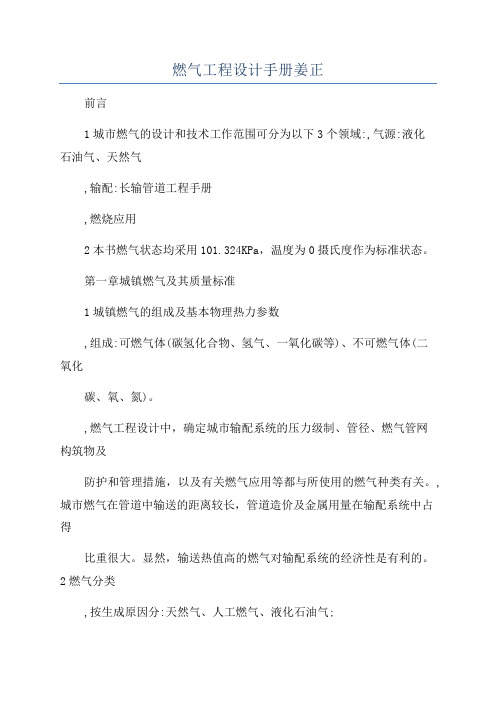
燃气工程设计手册姜正前言1城市燃气的设计和技术工作范围可分为以下3个领域:,气源:液化石油气、天然气,输配:长输管道工程手册,燃烧应用2本书燃气状态均采用101.324KPa,温度为0摄氏度作为标准状态。
第一章城镇燃气及其质量标准1城镇燃气的组成及基本物理热力参数,组成:可燃气体(碳氢化合物、氢气、一氧化碳等)、不可燃气体(二氧化碳、氧、氮)。
,燃气工程设计中,确定城市输配系统的压力级制、管径、燃气管网构筑物及防护和管理措施,以及有关燃气应用等都与所使用的燃气种类有关。
,城市燃气在管道中输送的距离较长,管道造价及金属用量在输配系统中占得比重很大。
显然,输送热值高的燃气对输配系统的经济性是有利的。
2燃气分类,按生成原因分:天然气、人工燃气、液化石油气;, 按燃烧热值分:高等热值燃气(HCV gas,热值30MJ/m^3以上,组分以烃类为主);中等热值燃气(MCV gas,热值20MJ/m^3左右,组分除H2和CO外还有甲烷等烃类);低等热值燃气(LCV gas,热值12~13MJ/m^3左右。
组分主要为H2和CO)。
,按燃气燃烧特性分类:按华白数(W=H/S^0.5,置换前后燃气具燃气压力相等时)大小分类:一类、二类、三类燃气。
H:热值;S:燃气相对密度。
华白数或广义华白数相等的两种燃气可以使用同一个燃具。
3对燃气质量的要求:复合相应的国家规范天然气爆炸极限:5%-15%;煤制气:6.5%-36.5%。
燃气加臭:加入四氢噻吩,约0.08mg/m?可达到臭味强度为2级的报警浓度,实际中加入大于0.08。
第二章燃气的物理和热力性质第三章城镇燃气用气负荷3.1城镇燃气用气复合的定义及分类定义:燃气系统终端用户对燃气的需用气量形成燃气最基本的负荷,主要取决于用户类型、数量及用气指标。
燃气用气按用户类型分类:居民生活用气、商业用气、工业企业生产用气、采暖通风和空调用气、燃气用气、电站用气、其他用气。
3.2城镇燃气复合的计算年用气量:根据城市发展规划和各类用户用气量指标确定。
工业用气体书籍

工业用气体书籍
有关工业用气体的书籍,你可以参考以下一些经典的著作:
《气体工程师手册》(Handbook of Industrial Gas Engineering)- Frank G. Kerry、Daniel M. Green
该手册涵盖了气体工程的各个方面,包括气体的性质、生产、传输、储存和应用等。
《气体工程与技术》(Industrial Gases Processing)- Frank G. Kerry
本书深入介绍了气体的生产、提纯、分离、储存和应用等方面的技术与工艺。
《气体分离技术》(Gas Separation by Adsorption Processes)- Douglas M. Ruthven
该书主要关注气体分离技术,介绍了吸附过程在气体分离中的应用,包括吸附剂的选择、工艺设计等方面的内容。
《气体工艺技术》(Gas Processors Suppliers Association Engineering Data Book)- GPSA
由气体加工供应商协会(GPSA)编写的工程数据手册,包含了丰富的气体工程数据和技术信息。
《气体液化工程》(Cryogenic Engineering)- Thomas M. Flynn
介绍了液化气体技术,包括液化气体的性质、液化过程、设备等方面的知识。
请注意,书籍的选择还取决于你具体感兴趣的气体领域,例如空气分离、氢气、氮气、氧气等。
在选择书籍时,建议查看目录和书籍评论,以确保其符合你的学术和应用需求。
德士古工艺手册(德士古水煤浆加压气化技术资料)

目录第一章:德士古水煤浆加压气化技术概况第一节:概述第二节:国外发展情况第三节: 国内发展情况第四节:德士古水煤浆加压气化技术有待改进第二章:煤及水煤浆的性质第一节:煤的工业分析和元素分析第二节:煤的工艺性试验第三节:德士古对水煤浆性质的要求第三章:气化原理及操作条件的选择第一节:德士古水煤浆加压气化原理第二节:气化反应条件的选择第四章:德士古水煤浆加压气化工艺流程及主要设备第一节:工艺流程叙述第二节:主要设备介绍第五章:开停车方法第一节:原始开车前的检查准备工作第二节:气化炉的烘炉第三节:正常开车第四节:正常停车第五节:紧急停车第六章:正常操作要点第七章:PLC和DCS简介第一节:联锁和可编程控制器(PLC)第二节:集中分散控制系统(DCS)第八章:一般故障及处理第九章:安全生产第一节:概述第二节:装置设计中的防范措施第三节:安全生产管理第一章德士古水煤浆加压气化技术概况第一节概述化学工业有限公司20万吨/年甲醇项目是新建一套利用神木本地所产烟煤作为原料,经空分、气化、净化、合成等几个化工工序,年产20万吨甲醇的生产装置。
其中气化装置是采用德士古水煤浆加压气化工艺,向甲醇生产制备合格水煤气。
煤气化已有一百多年的发展历史,先后开发了一百多种气化工艺和气化炉型,有工业应用前景的十余种。
煤气化分类无统一规定,最常用的是按原料在气化炉内的移动方式分为固定床、流化床和气流床三种:固定床气化是块煤从炉顶加入,自上而下经历干燥、干馏、还原、氧化和灰渣层,灰渣最终经灰箱排出炉外;气化剂自下而上经灰渣层预热后进入氧化层和还原层,生成的煤气显热用于煤的干馏和干燥。
固定床气化的局限性是对床层均匀性和透气性要求很高,要求入炉煤要有一定的粒(块)度及均匀性,对煤的机械强度、热稳定性、含碳量、灰熔点、粘结性、结渣性等指标都有比较严格的限制。
流化床气化是气化剂由炉下部吹入,使细粒煤(﹤6mm)在炉内呈并逆流反应,为了维持炉内的“沸腾”状态并保证不结疤,气化温度应控制在灰软化温度(T2)以下,要避免煤颗粒相聚而变大以致破坏流态化,显然不能使用粘结性煤。
- 1、下载文档前请自行甄别文档内容的完整性,平台不提供额外的编辑、内容补充、找答案等附加服务。
- 2、"仅部分预览"的文档,不可在线预览部分如存在完整性等问题,可反馈申请退款(可完整预览的文档不适用该条件!)。
- 3、如文档侵犯您的权益,请联系客服反馈,我们会尽快为您处理(人工客服工作时间:9:00-18:30)。
气体加工供应者协会是由各公司组成的一个联合机构,它为气体加工及有关工业必需品
的供应和服务提供专门知识。
该工程数据手册具体体现了这样一项主要的服务工作,它首次出版于1935年。
按英制单位出版发行的第九版已超过了十万册,被全世界的工程师、操作人员和大学生们广泛使用这本经修订的第十版工程数据手册,试图把现场和气体加工厂工程技术人员在确定操作和设计参数时所使用的数据和计算方法,连同基础设计资料一起汇编成一册,尽管电子计算机程序和其他先进设计技术的应用不断扩大,这本数据手册还是可以在估算、可行性研究、初步设计和对现场操作运行进行鉴定等方面帮助设计人员,是一本通用的、符合工程实际的指导性资料。
气体加工供应者协会认为:对工程数据手册进行修订应是一个不间断的工作.欢迎读者
提出批评和建议。
来信请寄:
Gas Processors Suppliers Association
6526E.60th St.
Tulsa, Oklahoma 74145
I《工程数据手册》的简要历史和发起单位
气体加工供应者协会的《工程数据手册》首次出版于1935年。
当时只是一种登载些
广告和简短技术资料的小册子。
后来的版本由于扩充了技术内容,逐渐成为气体加工工业- 本通用的技术参考书与此同时,这本书也为石油炼制,气体输送和石油化学工业方面的人员广泛使用。
气体加工供应者协会(GPSA)成立于1928年,当时的名字是天然气油供应者协会(NGSMA)。
主要目的是作为美国天然气油协会(NGAA)的服务机构
随着工业状况的变化,这两个机构都曾更改过名称。
1961年改为众所周知的天然气加工协会(NGPA)和天然气加工供应者协会(NGPSA); 1974年又改为现用的名称,即气体加工协会(GPA)和气体加工供应者协会(GPSA)
本书读者请注意,书中的许多参考文献可能是以出版当时这些机构的名字而署名的出版物
2采用国际单位制(5I)的《工程数据手册》
1980年气体加工供应者协会出版了采用国际单位制(SI)的《工程数据手册》,作为英
制单位第九版的姊妹篇。
它是在全世界日益广泛采用国际单位制的情况下出版的。
因此,这样一本书必将有助于从英制单位向国际单位制的过渡,从而满足现场工程师的需要
3.声明
气体加工供应者协会对于本书所述的被列人现有专利中的任何方法、设备或产品,或宣称包含有这样一种方法、设备或产品的专利的有效性,既不支持也不反对。
此外,本书中所包括的任何资料都不能明里或暗里解释为授权进行与专利权有关的任一方法、设备或产品的制造、销售或使用,也不能解释为担保任何人侵犯专利权可不承担任何责任。
