petrel快捷键
PETREL操作手册文字版(中文)essca

色标的定义: 色标的定义 1. 激活某一surface (点击选中). 2. 点击工具栏中的 Fill Color Table 按 钮. - 对于其他类型数据可遵循相同的方法 .例如:某一等容线图或某一属性图.
备注: 备注
设置色标的另外一种方法是打开某一 等值面,等容线和属性的设置窗口(双击 PETREL资源管理器中的对象名称)设 定颜色刻度和最大、最小值.
建立文件夹: 建立文件夹 1. 确定用于存放数据的文件夹的数目, 例如:地震线、等容线、断层多边形. 2. 从工具栏(单击Insert New Folder 按钮)或从菜单栏(Insert) 添加新文件 夹. 3. 鼠标左键双击文件夹名称(“New Folder”)对文件夹重新命名. 4.以数据类型对文件夹命名.
PETRELTM 操作手册(中文版)
北京阿什卡地球科学咨询服务公司 北京中关村大街甲38号 燕山大酒店公寓403室 邮编:100086 电话: 010-6256-4808 传真: 010-6256-4376 信箱: support@ 网站:
目录
1 载入数据 1.1 添加新文件夹 1.2 载入数据 1.3 属性、深度/时间和厚度的色标 1.4 质量控制 地震解释 2.1 断层解释 2.2 层位追踪 井相关 3.1 2D面板下的井相关 3.2 3D窗口下的井相关 创建/编辑井分层 创建 编辑井分层 4.1 创建井分层 定义模型 建立断层模型 使用 Key Pillars定义模型 6.1 6.2 编辑 Key Pillars Pillar Gridding 7.1 Pillar Gridding的处理步骤 7.2 网格构架的质量控制 创建层面网格 8.1 创建层面网格 时深转换 9.1 时深转换的处理步骤 9.2 使用井分层进行时深转换 划分地层 10.1 划分地层 10.2 截面的可视化和质量控制 10.3 输出 细分地层 11.1 细分地层 编辑3D网格 编辑 网格 12.1 更新3D网格 12.2 3D网格的手动编辑 创建油气水接触关系 13.1 创建油气水接触关系 13.2 接触关系的可视化
PROE常用快捷键大全
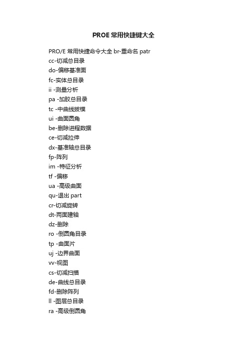
PROE常用快捷键大全
PRO/E 常用快捷命令大全br-重命名patr cc-切减总目录
do-偏移基准面
fc-实体总目录
ii -测量分析
pa -加胶总目录
tc -中曲线拔模
ui -曲面圆角
be-删除进程数据
ce-切减拉伸
dx-基准轴总目录
fp-阵列
im -特征分析
tf -偏移
ua -高级曲面
qu-退出part
cr-切减旋转
dt-两面建轴
dz-删除
ro -倒圆角目录
tp -曲面片
uj -边界曲面
vv-视图
cs-切减扫描
de-曲线总目录
fd-删除阵列
ll -图层总目录
ra -高级倒圆角
cu-切减面组
dk-草绘曲线
fr-恢复
rl -模型关系
uu -曲面总目录
ut -曲面修剪
en-环境总目录
ca-切减高级总目录
dn-投影曲线
fv-重定义
po -实体总目录
ue -拉伸曲面
ux -曲面延拓
ed -隐藏面
cg-倒角
dg-基准点总目录fn-插入模式
pe -拉伸加胶
sh -抽壳
ur -旋转曲面
uk -曲面拔模
ep-隐藏点
co-复制总目录dh-曲线+面
fm-镜像几何
pr -旋转加胶
tw -扭曲总目录us -扫描曲面
xz -截面总目录ea-隐藏轴
dy-坐标系总目录pw -扫描加胶
td -中平面拔模uo -曲面偏移
zz -设置总目录ec-隐藏坐标系da-基准面总目录hh -孔总目录
tr -替换
uc -曲面复制zn -设置名称。
154-文献资料-Pro E快捷键大全
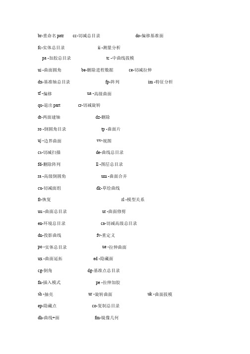
br-重命名patr cc-切减总目录 do-偏移基准面
fc-实体总目录 ii -测量分析
pa -加胶总目录 tc -中曲线拔模
ui -曲面圆角 be-删除进程数据 ce-切减拉伸
dx-基准轴总目录 fp-阵列 im -特征分析 tf -偏移 ua -高级曲面
qu-退出part cr-切减旋转
dt-两面建轴 dz-删除
ro -倒圆角目录 tp -曲面片
uj -边界曲面 vv-视图
cs-切减扫描 de-曲线总目录
fd-删除阵列 ll -图层总目录
ra -高级倒圆角 um -曲面合并
cu-切减面组 dk-草绘曲线
fr-恢复 rl -模型关系
uu -曲面总目录 ut -曲面修剪
en-环境总目录 ca-切减高级总目录
dn-投影曲线 fv-重定义
po -实体总目录 ue -拉伸曲面
ux -曲面延拓 ed -隐藏面
cg-倒角 dg-基准点总目录
fn-插入模式 pe -拉伸加胶
sh -抽壳 ur -旋转曲面 uk -曲面拔模
ep-隐藏点 co-复制总目录
dh-曲线+面 fm-镜像几何
pr -旋转加胶 tw -扭曲总目录
us -扫描曲面 xz -截面总目录
ea-隐藏轴 dy-坐标系总目录
pw -扫描加胶 td -中平面拔模
uo -曲面偏移 zz -设置总目录
ec-隐藏坐标系 da-基准面总目录 hh -孔总目录 pu -面组加胶
tr -替换 uc -曲面复制
zn -设置名称。
Petrel中断层Polygon编辑技巧
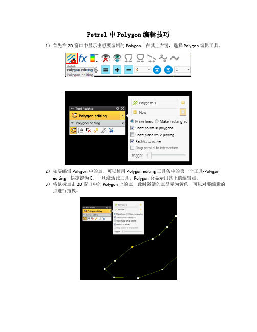
Petrel中Polygon编辑技巧1)首先在2D 窗口中显示出想要编辑的Polygon,在其上右键,选择Polygon编辑工具。
2)如要编辑Polygon中的点,可以使用Polygon editing 工具条中的第一个工具-Polygon editing,快捷键为E。
一旦激活此工具,Polygon会显示出其上的编辑点。
3)将鼠标点击2D 窗口中的Polygon上的点,此时激活的点显示为黄色,可以对要编辑的点进行拖拽。
4)如要对Polygon进行切断,则选择工具条的最后一个工具,Cut Polygon,此时鼠标变为类似刀锋的模式,用刀锋尖点击要剪断处,此时点击出会添加一个点,用上一步的工具去拖动此点,此时可以发现Polygon已断开。
5)如要在切断的Polygon上继续编辑或者画此Polygon,需要先激活画Polygon的工具-Add point to polygon工具,快捷键为A。
6)激活Add point 工具后,在所要编辑的Polygon上直接点击,查看切断的Polygon的首尾点,一般此时点击Petrel默认是从Polygon的末尾点继续来画,直接点击鼠标左键即可编辑。
7)如要从断开的Polygon的首点开始画,则需要将首点选中为黄色(可以使用第一步中的工具来选中),选中Add Point工具,按住Shift键,在靠近选中的黄色的点附近点击鼠标左键,即可继续以首点来画。
(注意此处,根据测试,按住Shift后点击鼠标左键时距离Polygon上点的位置越近,其越能编辑其附近的点。
)8)最后编辑完,如要闭合,则可以直接右键点击,在弹出的工具条上选择Close工具即可。
9)对于两条Polygon需要进行连接的,如果两条Polygon没有在同一个文件中,首先需要将两条Polygon合并到一个Polygon文件中。
此时可以使用Polygon Setting中的Operation中Polygon Operation中的Append工具来完成。
PETREL简易操作手册(地球物理部分)
Display window 3D (View mode) 左键旋转。 左键+ Ctrl / 滚轮 平移。 左键+ Ctrl+Shift / 左键+滚轮 放大缩小。 右键弹出图形设定的菜单。 Display window 2D (View mode) 左键放大缩小。 左键+ Ctrl 平移。 左键+ Ctrl+Shift 旋转。 右键弹出图形设定的菜单。 Plot windows – 除了Well Section window (View mode) & Viewport (除了Histogram window) 左键平移。 左键+ Ctrl+Shift 放大缩小。 Viewport edges (仅限坐标显示时) 左键移动到边缘。 左键+ Ctrl 平移。 左键移动到角落。 左键+ Ctrl 放大缩小Viewport的范围。 Visual objects 左键移动物体。 Well Section window (View mode) 左键选择。 Petrel Explorer. 就像Windows Explorer一样,数据被存储于文件夹或者子文件夹中。 左键可以打开或者关闭文件夹,托拽一个图标到一个新文件夹。 也可以在当前显示窗口选择是否显示该数据体。 右键弹出一个菜单,用于设置和操作选择的数据。 Process diagram 左键选择流程步骤。注意选择了流程步骤以后Function Bar汇兑赢得显示出来一系列的只和这个指 定流程有关的按钮。 右键弹出一个下拉菜单包括处理流程对话框和Float in Main Window选项。
5) 选择 MD, INCL, AZIM 格式,MD 列选 1,INCL 列选 9,AZIM 列选 8,OK For All。 6) 加载测井曲线:右键单击 “wells” 选择 import(on selection), 文件名为
Petrel操作手册(中文)

创建/编辑井分层 创建/编辑曲线填充颜色 添加新井
3.1 2D相关面板下的井相关
井相关 编辑曲线颜色填充
1. 双击流程栏中的Well Correlation ,点 击“Create new well section”按钮,添加 相关面板. 2. 在well 文件夹中选择待添加到面板 中的井. 3.在well 文件夹Global Well Logs中选 择相关连井剖面(显示窗口)中使用的测 井曲线. 4. 选择 make/edit well tops 按钮. 5. 编辑井分层的位置.
- 观察3D下的变化.
10. 改变地震剖面的settings 窗口中颜 色 (在 colors 标签中). 移动颜色设置中 的不透明曲线,观察变化.
备注:
3D下对地震解释的结果进行质量控制 的最佳方法是使用地震剖面播放器显 示数据体的内部信息.
3. 井相关
PETREL可以在屏幕上进行快速相关操作. 在井剖面可以进行多井显示,层位拾取,基 准面校正,加入新井和相关过的井进行比较.
2 地震解释 2.1 断层解释 2.2 层位追踪
3 井相关 3.1 2D面板下的井相关 3.2 3D窗口下的井相关
4 创建/编辑井分层 4.1 创建井分层
5 定义模型 6 建立断层模型
6.1 使用 Key Pillars定义模型 6.2 编辑 Key Pillars
7 Pillar Gridding 7.1 Pillar Gridding的处理步骤 7.2 网格构架的质量控制
为了达到数据的最佳显示,定义颜色模板很重要. 对于同类数据对象Petrel拥有多种模 板描述色标的参数设置.例如:属性、深度/时间、厚度.
色标的定义:
1. 激活某一surface (点击选中).
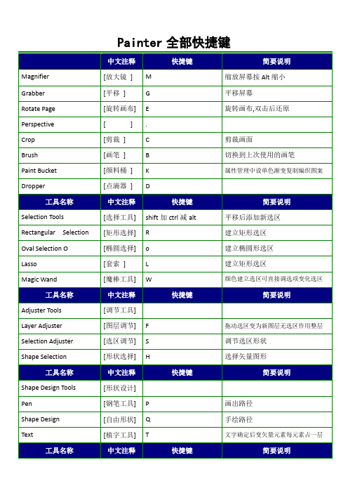
painter快捷键大全
Ctrl+Click 减选择原文Alt+Click
RemoveRangeofColorsfrom Sel
拖动鼠标从存在的选择区减框选颜色
Adjuster Tools
[调节工具]
Layer Adjuster
Shift+Alt+Ctrl
移动图层原文Ctrl除导航\形状选择
Selection Adjuster
[隐调色板]
Ctrl+H
控制调色板的显示和隐藏
Zoom In
[放大视图]
Ctrl++
放大
Zoom Out
[缩小视图]
Ctrl+-
缩小
Full Screen Window
[全屏显示]
Ctrl+M
全屏
Screen Navigation
[屏幕导航]
Center Image
[居中显示]
Spacebar+Click
Click last point添加曲线先点击最后一点
Add to Current Point
Shape Design
[形状设计]
Click and draw from endpoint添加最后一点
Add to Current Endpoint
Shape Objects Tools
[形状对象]
Rectangle Constrain to Square
[形状设计]
Pen
[钢笔工具]
P
画出路径
Shape Design
[自由形状]
Q
手绘路径
Text
[植字工具]
petrel教程
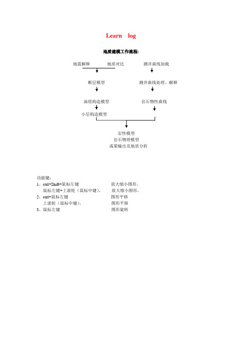
Learn log地质建模工作流程:地震解释地质对比测井曲线加载断层模型测井曲线处理、解释油组构造模型岩石物性曲线岩性模型岩石物理模型成果输出及地质分析功能键:1、ctrl+Shift+鼠标左键放大缩小图形。
鼠标左键+上滚轮(鼠标中键),放大缩小图形。
2、ctrl+鼠标左键图形平移上滚轮(鼠标中键),图形平移3、鼠标左键图形旋转建新工区lxj1 .pet一、建井文件夹new well folder在Insert的new folders→点New Well Floders1、加头文件在lxj1.pet Input窗下,右健点Wells→选Import (on select)…出现Import File输入窗中,点Petrel projects –-> cha19 → Well-data目录, 选文件名:文件类型:well heads(*.*)文件格式例子:WellName X-Coord Y-Coord KB TopDepth BottomDepth Symbol0 2534 Oil34/10-A-15 61757.5 30147.1 23.6 0 3133 Gas34/10-A-21 62165.3 32653.8 12.6 0 2431 Dry34/10-A-27 66552.1 31629.3 23.6 0 2986 MinorOil ......按打开,出现Import Well Heads窗,图如下:在窗口中参考Header info提供的列位置,填好列号,例如井名Name 1列X-坐标X-coordina 2列Y-坐标Y-coordina 3列补心Kelly bushing 4列井符号Well symbol 7列顶界深Top depth 5列底界深Bottom depth 6列在Extend well处选顶扩展或底扩展多少米,例如20米。
按OK,确定。
如果有不合适的井数据,会有提示指出,表示那些井不被加入。
- 1、下载文档前请自行甄别文档内容的完整性,平台不提供额外的编辑、内容补充、找答案等附加服务。
- 2、"仅部分预览"的文档,不可在线预览部分如存在完整性等问题,可反馈申请退款(可完整预览的文档不适用该条件!)。
- 3、如文档侵犯您的权益,请联系客服反馈,我们会尽快为您处理(人工客服工作时间:9:00-18:30)。
Shortcut Keys in PetrelThere are a number of shortcut keys in Petrel. The shortcut keys allow the user to increase speed and efficiency in their daily work. Some of them are process restricted and will be available only when certain process steps are active.Shortcut keys related to Microsoft Windows:F3 sets focus to Work areaPress ALT and TAB to switch between applications open in Windows.CTRL and ESC will open the Windows Start menu.TAB will move between edit boxes in an open menu.Arrow keysThe arrow keys on the keyboard can be used to move data around in the Display window. If nothing has been selected in the Display window, the arrow keys will move the camera, i.e. the position from which you are moving the data.If you select a point, a Shape Point in the Display window, the arrow keys and the Page Up and Down will move the selected point. Go to the Project pull-down menu (in the Menu bar), select Project Settings and go to the Settings 1 tab- here the translation increment can be changed.Shortcut keys in the Menu barThe different menus can be opened by clicking on them or by using ALT and the underlined letter in the name, for example, ALT and F to open the File menu.To select something from an open menu, either click on it, or type the letter underscored in the selection you want, e.g. O for opening a project from the File menu.Opening a Project:z CTRL and N will start a new project.z CTRL and O will open an existing project.z CTRL and open project from project link will open a project with no windows.z CTRL and open project will open a project with no windows.z CTRL and double-click on project in file browser will open a project with no windows.z CTRL and single-click on project in file browser + Open will open a project with no windows.z Other shortcuts:z CTRL and I will import a selected data file and place it at the bottom of the Input pane.z CTRL and M will open the Reference project tool.z CTRL and S will save the current project.z CTRL and E to export selected files (files selected in the Explorer panes).z CTRL and P to print what is displayed in the Display Window.z CTRL and Z will undo the last editing action in process steps such as Fault Modeling, Seismic interpretation, etc.z CTRL and Y will redo the last editing action in process steps such as Seismic interpretation, etc.z CTRL and X will cut the active (selected) item in the Explorer panes.z CTRL and C will copy the active (selected) item in the Explorer panes.z CTRL and V will paste a previously Cut or Copied item in the active (selected) folder in the Explorer panes.If a folder is not selected, the item will be pasted at the bottom of the Explorer pane.z Delete will delete an object selected in Petrel Explorer or in the Display window.z CTRL and A will select all items in the Display window, e.g. all polygons if a file with polygons is displayed (in Select/Pick Mode).z F1opens the Online manual in windows format for explanation and examples.z F11View full screen (of the active window in Petrel).Shortcut keys related to the Explorer panesz Minus key or Left arrow key collapses the selected iconz Plus key or the Right arrow key expand the selected iconz CTRL and Up selects previous siblingz CTRL and Down selects next siblingz Space bar toggles selected icon (visualize)z Enter activates objects and foldersz ALT and Enter opens Settings dialog for highlighted object or itemz Menu key opens context menu of the activated object or folder. To close, hit Escz F2 (or two single mouse clicks) for renaming active object or folderCTRL and T activates the Inpu t paneCTRL and L activates the Mode l s paneCTRL and R activates the P r ocesses paneShortcut keys related to the Display windowSee also the shortcut keys related to the Menu bar.z V switches to Viewing Modez Z activates the Magnifyz P activates the Select/Pick Mode.z Esc toggles between Viewing Mode last selected action in 2D and 3D windows.z SHIFT and Esc toggles between Viewing Mode and Select/Pick Modez Arrows on the keyboard will scroll the view of an item in the Display window (in Viewing Mode).z Home will bring the displayed item back to home position if the Set Home Position tool has been used.z S activates the Target Zoom (works in Viewing Mode in a 3D window).z CTRL and U activates the View all option; centers all data in the middle of the display window.z CTRL and J activates the selected Map view position.z CTRL and Tab opens a short cut menu for panes and open display windows in Petrel.Shortcut keys related to the IntersectionTherethe Manipulate Plane Select/Pick Mode.z M activates the Manipulate Plane tool.z D activates the Measure Distancez CTRL and B toggles the Toggle Visualization on Planez Arrows left and right will turn the plane around vertically with a constant tilt. Note that the plane cannot move if it is aligned North to South or East to West.z Arrows up and down will change the tilt of the plane. The alignment will be kept constant. Note that the plane cannot be tilted if it is aligned vertically or horizontally.z Page Up and Down will move the plane along its normal.Shortcut Keys related to Make/Edit Polygonsz N to start a New Polygon.z SHIFT and P to Show Pointsz P activates the Select/Pick Mode.z E to Select and Edit/Add Pointsz B to activate the Bounding Box Select tool (2D window only).Shortcut Keys related to Well Correlationz A to activate the Paint discrete log class .z F to activate the Flood discrete log class.z SHIFT and S to Pick up discrete log class.z L to activate Create/Edit continuous logs.z SHIFT and C to activate Create/Edit Comment log.Shortcut Keys related to Make/Edit Well Topsz T to activate Create/Edit Well Tops tool.z N to Add New Well Tops Surface .Shortcut keys related to Seismic InterpretationSince the seismic interpretation is performed on an intersection, the shortcut keys for General Intersection will also function in the Seismic Interpretation process step.z B- to activate the Bounding Box Selectz SHIFT and B- to activate the Selection Paintbrush tool (All windows)z Del-to delete selection.z P-activates the Select/Pick Mode.z X-to activate eraser mode.z(+) / (-)- increase / decrease the size of the eraser (when active)z PgUp / PgDn- Move the active seismic section by a given increment (All windows)z SHIFT and S- Activates fault or horizon (All windows)z F- Fault interpretation (All windows)z N- New Fault stick/interpretation (All windows)z H- Horizon Interpretation (All windows)z U- to set manual drawing mode .z A- to set 2D seeded autotracking mode .z SHIFT and A- to set 3D seeded autotracking mode .z G- to set 2D guided autotracking mode .z R-to set paintbrush autotracking mode (2D window only).z SHIFT and R- to set active box autotracking modez Y- select parent pointsz SHIFT and Y- select child points (3d window).z Z-Zoom (Interpretation window).z CTRL and Z will undo the last editing action.z CTRL and Y will redo the last editing action.z SHIFT and Z will unmagnify (only if magnifier has been used in the Interpretation window.z(+) / (-)- Zoom in/out (Interpretation window).z L- Select Inline Intersection (Base map and 3D windows).z SHIFT and L- Select Crossline Intersection (Base map and 3D windows).z K- Select any visible line, i.e. inline, crossline, general vertical intersection or 2d line (Base map and 3D windows) or redisplay previous intersectionz SHIFT and K- redisplay next intersectionz C- Create Arbitrary Polyline Intersection (Base map and 3D windows).z SHIFT and C- Create Seismic Aligned Polyline Intersection (Base map and 3D windows).z O- select composite selection (Base map and 3D windows) or compose with intersecting line (Interpretation window).z W- draw arbitrary composite intersectionsz SHIFT and W- draw aligned composite sectionsz I- compose with inline (Interpretation window).z SHIFT and I- compose with crosslinez Q- clip and extend composite (Interpretation window).Shortcut Keys related to Pillar Griddingz SHIFT and A activates the Set Arbitrary Directionz SHIFT and B activates the Set Part of Grid Boundaryz SHIFT and I activates the Set I-Directionz SHIFT and J activates the Set J-Direction tool.z N activates the Set Number of Cells for the Selected Connection tool.z B activates the Create External Grid Boundaryz I activates the New I-Trendz J activates the New J-Trend tool.z SHIFT and P activates the Show Points in PolygonsShortcut Keys related to Facies Modelingz L activates Pencil tool .z B activates 3D Brush tool .z A activates Airbrush tool .z F activates Fill Selected Facies Code tool .z SHIFT and S activates Adapt facies code from Image tool .Shortcut Keys related to Workflow editorz CTRL and W will open the active workflow.。