斯伦贝谢petrel教程3
Petrel教程

用户界面
每一个对象都有一个设置窗口,在Petrel浏览 器中在每个对象上点击右键就可以进入设置 窗口。
信息定义窗口 – 用来改变名称,具体内容 根据模版而定。
格式定义窗口 – 定义色彩,线条粗细,等 值线,网格,等。
介绍Petrel
讲解内容大纲
1
介绍Petrel
2
数据准备与加载
3
显示参数设置,如灯光、光标等。
+/• 每个文件夹靠点击其前面的
+/-键来控制打开/关闭。
粗体显示 • 粗体显示的项目表示是处于激活状
态的项目,点击某个项目使其显示 为粗体,表示选中该项目。
介绍Petrel
用户界面
Geology/地质 Seismic/地震
Modeling/建模
Simulation/数模 Geology/地质
2- 将先前生成的层面的surface 按顺序输入
3- 点击“Apply”,即生成 “Horizon”(构造层面)
Make Horizon
构造模型的建立
构造模型的建立
Layering
1- 点击进程窗口中 “Structural Modeling” 下的“Layering”选项, 弹出对话框;
2-对于每个层设置“a” 为“Follow Base”,“b”为“2” (即为垂向最小单元 为2m);
3- 点击“Apply”,完成 对层的细化。
a
b
构造模型的建立
讲解内容大纲
1
介绍Petrel
2
数据准备与加载
3
构造模型的建立
4
属性模型的建立
讲解内容大纲
Property Modeling 离散化曲线
斯伦贝谢公司PetrelEclipse授权教程
斯伦贝谢公司Petrel & Eclipse授权教程
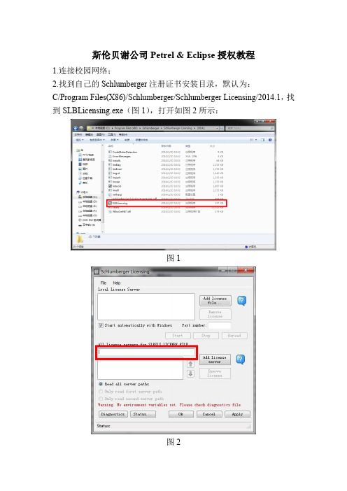
1.连接校园网络;
2.找到自己的Schlumberger注册证书安装目录,默认为:
C/Program Files(X86)/Schlumberger/Schlumberger Licensing/2014.1,找到SLBLicensing.exe(图1),打开如图2所示:
图1
图2
3.在图2红色框区域输入:*************.222.72,然后点击Add License server,结果如图3所示
图3
然后依次点击Apply、Ok,证书服务加载完毕。
4.打开电脑中Petrel安装目录,默认为:
C/Program Files/Schlumberger/Petrel 2014,找到Petrel.exe,如图4所示。
图4 5.打开软件,出现如图5界面。
图5
6.选中如图红色区域,点击ok,即可打开软件,如下图所示。
图6
7.大部分用户在这一步即可完成软件的授权过程,如按照上述步骤无法完成,可尝试以下操作:
(1)关闭电脑防火墙;
(2)设置hosts文件,具体操作为:
修改电脑里C/windows/system32/drivers/etc 目录下的hosts文件,里面加一条:
118.228.222.72 DELL-PC。
PETREL简易操作手册(地球物理部分)
ESSCA Inc.
练习 2-3 加载分层数据
分层数据是指一个层位或者一个断层与井轨迹发生交叉,在井上的一系列标记。输入数据主要是针对 位置(X, Y, Z坐标),以及名字和所归属的井名。另外,数据里可能还包括一些其他信息,诸如解 释者姓名、测量深度、时间值、一个地层单元的属性平均值等等。同时也可以指派数据的类型,比方 说,HORIZON、FAULT和OTHER。
-7-
ESSCA Inc.
定义好数据内的那一列与Petrel需要的信息对应。 按 OK. 井头信息文件就是一个简单的ASCII码文件,其中包含了按列排列的一些井头信息。 相应信息如下:
Well name (井名)- 必需(必须唯一) Unique well id (油井注册序列号)- 可选 X coordinate (X坐标)– 必需 Y coordinate (Y坐标)– 必需 Kelly Bushing (KB) value (补心海拔)- 可选 Well symbol (井符号)- 可选 Top depth (MD) (顶深)- 可选 Bottom depth (MD) (底深)– 可选 用户可以输入井符号的名字以代替井符号的代码。不过注意井符号的名字不能包含空 格,但是可以有逗号、下划线等等。 3) 用户可以为不同的井别的井建立自己的子文件夹: 右键单击 “wells” 选择 insert folder,双击 “well sub folder” ,可以在“info” 栏内修改文件夹的名字,诸如 “Injectors” 等。
文件名和井名匹配对话框。OK 关闭此对话框。 -9-
ESSCA Inc.
井轨迹数据应该是ASCII码文件个时,按列排放。数据中包含几种可能的信息组合: Measured depth(测深), inclination(倾角), azimuth(方位角) True vertical depth(真垂深), X-offset(X偏移量), Y-offset(Y偏移量) (MD可选) True vertical depth(真垂深), X, Y (MD可选) X, Y, Z (MD可选)ຫໍສະໝຸດ 练习1-1 启动Petrel
PETREL操作手册文字版(中文)essca

模型训练问题
01
训练参数设置不当
检查训练参数是否合理,如学习率、 迭代次数等。
训练数据不足
增加训练数据量或采用数据增强技 术。
03
02
特征工程不合理
尝试进行特征选择、特征转换等操 作,以提高模型性能。
模型过拟合
采用正则化、早停等技术防止过拟 合。
04
模型部署问题
部署环境与训练环境不一致
确保部署环境与训练环境一致,包括操作系 统、依赖库等。
petrel操作手册文字版(中 文)essca
目录
• 简介 • petrel操作流程 • petrel使用技巧 • petrel常见问题及解决方案 • petrel与其他软件的比较
01
简介
petrel软件概述
01
是一款海洋地球物理勘探软件,用于处理、分析和可视化地震 数据。
02
提供了一系列强大的工具,帮助用户快速高效地进行数据处理
易用性
Petrel在易用性方面更胜一筹。其界面设计直观,使得初学者可以快速上手。而TensorFlow的学习曲 线相对陡峭,对于新手可能有些吃力。
运行效率
在运行效率上,TensorFlow得益于其高效的计算图优化,通常能提供更快的训练速度。
petrel与pytorch的比较
动态计算图
Petrel在动态计算图方面强于PyTorch。Petrel支持即时编译和优化, 这使得它在处理复杂模型和算法时更加高效。
模型训练
01
在Petrel中,选择“新建模型”选项。
02 选择要使用的算法和参数,并进行模型训练。
03
在模型训练过程中,可以查看训练日志和监控模型的
性能指标。
模型评估
Petrel操作手册(中文)

创建/编辑井分层 创建/编辑曲线填充颜色 添加新井
3.1 2D相关面板下的井相关
井相关 编辑曲线颜色填充
1. 双击流程栏中的Well Correlation ,点 击“Create new well section”按钮,添加 相关面板. 2. 在well 文件夹中选择待添加到面板 中的井. 3.在well 文件夹Global Well Logs中选 择相关连井剖面(显示窗口)中使用的测 井曲线. 4. 选择 make/edit well tops 按钮. 5. 编辑井分层的位置.
- 观察3D下的变化.
10. 改变地震剖面的settings 窗口中颜 色 (在 colors 标签中). 移动颜色设置中 的不透明曲线,观察变化.
备注:
3D下对地震解释的结果进行质量控制 的最佳方法是使用地震剖面播放器显 示数据体的内部信息.
3. 井相关
PETREL可以在屏幕上进行快速相关操作. 在井剖面可以进行多井显示,层位拾取,基 准面校正,加入新井和相关过的井进行比较.
2 地震解释 2.1 断层解释 2.2 层位追踪
3 井相关 3.1 2D面板下的井相关 3.2 3D窗口下的井相关
4 创建/编辑井分层 4.1 创建井分层
5 定义模型 6 建立断层模型
6.1 使用 Key Pillars定义模型 6.2 编辑 Key Pillars
7 Pillar Gridding 7.1 Pillar Gridding的处理步骤 7.2 网格构架的质量控制
为了达到数据的最佳显示,定义颜色模板很重要. 对于同类数据对象Petrel拥有多种模 板描述色标的参数设置.例如:属性、深度/时间、厚度.
色标的定义:
1. 激活某一surface (点击选中).
Petrel操作技巧

Petrel操作技巧Petrel 地震地质解释和建模使⽤技巧2015斯伦贝谢科技服务(北京)有限公司Copyright Notice2015 Schlumberger. All rights reserved.No part of this manual may be reproduced, stored in a retrieval system, or translated in any form or by any means, electronic or mechanical, including photocopying and recording, without the prior written permission of Schlumberger Information Solutions, 5599 San Felipe, Suite 1700, Houston, TX 77056-2722.DisclaimerThe License Agreement governs use of this product. Schlumberger makes no warranties, express, implied, or statutory, with respect to the product described herein and disclaims without limitation any warranties of merchantability or fitness for a particular purpose. Schlumberger reserves the right to revise the information in this manual at any time without notice.Trademark InformationSoftware application names used in this publication are trademarks of Schlumberger. Certain other products and product names are trademarks or registered trademarks of their respective companies or organizations.⽬录1.1 斜井井轨迹在Well Section窗⼝中的4种投影⽅式原理 (4)1.2 Well section下打印连井剖⾯图 (8)1.3 well section下设置隐含的边界显⽰单曲线道局部充填 (11)1.4 well section下井上解释断层断距显⽰ (15)1.5 在指定深度范围内修改测井曲线 (18)1.6 Petrel和Excel⼀体化快速⽣成测井解释成果表 (19)1.7 Petrel2014如何加载TVD/TVDSS索引的测井曲线 (23)1.8 对不同井的测井曲线使⽤不同的算法进⾏粗化 (25)1.9 拼接不同深度段的测井曲线 (27)1.10 每种沉积相的测井曲线范围统计 (29)1.11 3Dwindow中如何连接well top (32)1.12 Petrel中如何快速⽣成断层Polygon (33)1.13 surface上对特定polygon范围进⾏单独赋值 (34)1.14 如何实现多边形的合并Merge Polygons (37)1.15 Petrel如何在Surface上显⽰图⽚ (40)1.16 如何将多个surface对应的的平均值同时输出到excel表格中 (42) 1.17 根据两个Surface⽣成TST和TVT Map (43)1.18 如何将Well heads在Surface附近显⽰ (45)1.19 在Make surface的时候如何将结果往边界多边形外扩⼀些 (47) 1.20 如何计算某个zone内饱和度曲线的加权平均值 (50)1.21 如何由离散相曲线计算砂体或薄互层的厚度 (51)1.22 如何批量⽣成zone的厚度图 (53)1.23 计算特定井和特定Zone的砂层厚度 (54)1.24 批量计算单井上每个zone中砂岩段的数量 (56)1.25 ⽤曲线截断创建离散的净厚度图 (60)1.26 地震体三维渲染显⽰不清晰时的解决⽅法 (64)1.27 如何使⽤⽤户⾃定义边界切割地震体 (65)1.28 三维显⽰沿层切割地震体 (67)1.29 如何在Petrel中如何往已有的Survey中加载相邻位置的地震体 (68) 1.30 如何计算多⼝井周层⾯属性统计值 (71)1.31 Petrel中地震Vintage的管理 (76)1.32 Petrel中如何按地震⼯区加载⼆维地震数据 (80)1.33 Petrel 2014中合成地震记录显⽰设定 (84)1.34 Petrel 2014中对于切地震剖⾯的快速设置 (87)1.35 Petrel中如何对地震数据进⾏抽稀 (88)1.36 Petrel中如何沿井轨迹提取地震数据的振幅 (89)1.37 Petrel中如何实现地震解释层位的合并 (90)1.38 如何加载2D数据 (92)1.39 依据Horizon和Fault剪切地震数据体 (93)1.40 如何在Petrel移动地震数据体 (94)1.41 按⽤户⾃定义范围到处2D地震测线 (96)1.42 Petrel如何加载信息缺失的⼆维地震数据 (101)1.43 将Jason 的⼦波加载到Petrel中 (105)1.44 如何在Petrel中提取可靠的⼦波 (107)1.45 如何在Function window按照某⼀曲线的属性显⽰交会图 (109) 1.46 如何在Function window按照深度筛选交会图 (110)1.47 如何⽤Zone log过滤直⽅图 (113)1.48 如何合并多井的Checkshot数据到⼀个⽂件夹 (114)1.49 Petrel中如何做好井震对⽐ (116)1.50 如何将井分层与矫正后的Vo⾯均显⽰在X,Y,V域 (123)1.51 如何批量输出井斜 (125)1.52 使⽤部分井进⾏Data Analysis (126)1.53 Petrel 中如何批量修改井类型 (130)1.54 如何加载多⼝井轨迹在⼀个⽂件 (131)1.55 Petrel⼯区井的X坐标没区带号 (134)1.56 井坐标为经纬度如何加载 (135)1.57 ⼀种简单安全的⽅式添加⾃定义井符号 (136)1.58 Petrel中蚂蚁体的运算技巧 (140)1.59 Petrel蚂蚁体介绍及参数设置 (144)1.60 如何利⽤蚂蚁体提取⼩断裂 (151)1.61 如何⽣成Azimuthal Map (155)1.62 如何在Petrel中加载经纬度的点数据 (157)1.63 使⽤⾃定义速度函数进⾏时深转换 (159)1.64 在Function Window中如何如⽤第三变量调整数据点的颜⾊ (161) 1.65 Petrel中如何创建客户化岩性符号 (162)1.66 Petrel如何按宽度显⽰岩性 (164)1.67 如何批量移动断层 (168)1.68 如何⽣成⽤户⾃定义的离散属性⾯ (170)1.69 如何在Petrel中有效地组织数据 (173)1.70 如何在Petrel中⾃动形成断层多边形 (175)1.71 如何使⽤Clean Project History选项清理⼯区历史 (177)1.72 神经⽹络分类中的主成分分析 (178)1.73 如何对井⼀定范围外的⽹格粗化的同时保留井附近的原始⽹格 (182) 1.74 以⼀种⾃定义的⽅式进⾏⽹格粗化 (186)1.75 如何在现有速度模型中加⼊其他速度异常体 (188)1.76 Petrel2014 Structural Framework⼯区保存错误解决⽅案 (189)1.77 剥蚀带的建模技术 (191)1.78 在属性建模中使⽤Local varying azimuth (192)1.79 多条⼆维测线速度数据建⽴速度模型 (195)1.80 如何对属性模型进⾏切割或者局部更新 (203)1.81 ⼀个简单的⼯作流计算⼏个层⾯的均值并输出 (205)1.82 如何⽤Petrel Workflow快速整理层位数据 (207)1.83 如何⽤Petrel Workflow快速整理断层多边形数据 (210)1.84 运⽤workflow批量⽣成变化变程的属性模型 (211)1.85 运⽤Workflow统计地震测线长 (214)1.86 运⽤Workflow统计井间距离 (215)1.87 运⽤Workflow批量⽣成断层与上下盘层位交线 (218)1.88 Petrel全新的断层解释-建模⼀体化⼯作流 (220)1.89 使⽤Inspector⼯具修改模型中单个⽹络的属性 (221)2.1 PetroMod中如何优化断层在剖⾯上的形态 (223)2.2 PetroMod 中如何进⾏油源对⽐ (225)2.3 PetroMod模型在Petrel中显⽰ (228)3.1 GeoX中如何客户化输出GeoX Report到Excel中 (230)3.2 GeoX新许可设置流程 (237)1.1 斜井井轨迹在Well Section窗⼝中的4种投影⽅式原理在Petrel的连井剖⾯窗⼝(Well Section Window)中显⽰斜井轨迹是⼀个⼗分实⽤的功能。
斯伦贝谢petrel教程3
A. Double-click on the top horizon B. Go to Operations tab, Calculations folder, and select Volume/area
versus depth C. Specify min and max Z values (the depth interval to calculate
C. Incorporate fluid contact “Set Z=A where:” Z>A (base) or Z<A (top)
3-C
Volume processing (2D Grids)
Build gross rock thickness grid
1. Open the Surface calculator (right click on a surface and select calculator)
surface (constant) C. Specify base level D. Execute and inspect the result in the Petrel Message log
Between a surface and a plane
Volume processing (2D Grids)
Make sure they close Make sure they encompass the correct area C.In the Select/pick mode (arrow) touch a polygon to see its area, or Execute for Area and Length in Calculations for the Polygon.
Pearson BTEC International Level 3 工程教学指导书说明书
BTEC INTERNATIONAL LEVEL2QUALIFICATIONS IN ENGINEERINGUNIT3:INVESTIGATING AN ENGINEERING PRODUCTUnit 3: Investigating an Engineering ProductDelivery guidanceApproaching the unitThis unit is mandatory for all sizes and pathways other than the Award size (where it is an optional unit) and should be delivered early in a programme, as a good knowledge and understanding of engineering materials and processes will support learning in many other units.The focus of this unit is for learners to investigate and analyse the materials and processes used in the component parts of engineering products. Learners should be given full access to a range ofengineering products that are made from at least two component parts and from different materials.For example, for an adjustable wrench you may ask learners to focus on the main body and the handle cover, for a low voltage circuit tester you may ask learners to focus on the spike and the end cap and for an emergency stop unit you may ask learners to focus on the push button and the surfacemounting case. All of these engineering products have at least two component parts that aremanufactured using different processes and made using different materials. It would be ideal iflearners were able to disassemble the engineering products so they can see all of the details and how they are assembled, although it is recognised that this may be difficult. Learners must be provided with support to understand the purpose and function of each chosen engineering product as well as the chosen component parts of each engineering product. This understanding is essential and a really important factor that enables learners to carry out a contextual investigation and analysis of thereasons why the specific materials and specific processes have been used to make them.Nonetheless, the delivery approach should be mainly practical and should encourage learners to develop their knowledge of how to use various engineering processes (plus the related practical skills) and how to work with various materials when making a range of component parts. This background understanding will support learners to recognise why certain materials and processes are the most suitable for making a range of component parts. Again, it would be ideal if learners could actually make some of the component parts from the chosen engineering products, although it is again recognised that this may be difficult.The key to learner success in this unit is to bring together the practical knowledge of materials and processes with a contextual understanding of why the materials have been used in the component parts of engineering products and why the processes have been used to make the component parts.You could use a range of delivery methods in this unit, such as:•discussions - class and small group•individual or group presentations - covering engineering materials/properties,engineering processes/features and scales of production•demonstrations - covering the safe preparation, set-up and use of differentengineering processes to machine, shape, manipulate, cast, mould and joindifferent engineering materials•engineering product/component part analyses - illustrating contextual information about why the specific materials and specific processes have been used to makethem•worksheets and example assessments - to confirm knowledge and understanding.You can involve local employers in the delivery of this unit if there are localDelivering the Learning aimsLearning aims A and BThe most appropriate approach when delivering the Learning aims for this unit is to consider how the Topics (A1, A2 etc) from the Content section in the unit specification link together.An integrated rather than a sequential approach to delivery would be most appropriate.You could start most of the lessons by introducing some materials and their properties and some processes and their key features, as well as the different scales of production (at appropriate points). It will be important to ensure full coverage of Topics A1 to A4 and Topics B1 to B5 in the Content section of the Unit 3 specification during these presentations. Use some easily accessible engineering products (from those available in the centre, for example the Sample Pearson Set Assignment Brief for Unit 3 includes an engineers’ vice) to explain the reasons for the selection and application of the materials in the component parts of the engineering products and the reasons for the selection and application of the processes used when making the component parts of the engineering products.The bulk of the delivery for this unit should focus on the learners actually using various engineering processes (plus the related practical skills) and various materials to make a range of component parts.Demonstrate to learners how to safely use different engineering processes to, for example (not an exhaustive list):•drill, turn and mill a carbon steel cap (Topics B1, A1, A4 and B5)•shear, bend and fold an aluminium container lid (Topics B2, A1, A4 and B5)•vacuum form the cover for a LDPE key pad (Topics B3, A2, A4 and B5)Learners should be given time to safely use the different engineering materials and processes to make the component parts of engineering products. Learners will gain most of their knowledge and understanding for this unit from this practical experience of using materials and processes and the Tutor should try to ensure the fullest coverage of Topics A1 to A4 and Topics B1 to B4 in the Content section of the Unit 3 specification during these activities. The Tutor should also emphasise to learners that safety is vital but that they are not looking for accuracy or efficiency when making the component parts; the really important aspect of this practical learning is to recognise the characteristics of different materials and what different processes can do.Central to the required learning is the review activities to contextualise the understanding. Learners should already know the function and purpose of the component parts they have made and they should then assess why the materials used were suitable and why the processes used were suitable.After this it would be appropriate to move into specific investigative activities related to the component parts of engineering products. Tutors should provide a range of physical examples of engineering products that are made from at least two component parts and from different materials (the engineering products should be different from those shown to learners before but should be of a similar level of complexity). Learners could move around on a carousel and complete a template worksheet that requires them to carry out an analysis activity for the two specified component parts of each engineering product. The analysis activity could be based on the Sample Pearson Set Assignment Brief but for different engineering products. Before this the Tutor needs to emphasise to learners that they must, during the analysis activities: a) link the purpose and function of each component part to the favourable properties of the specificmaterial/s used; and b) consider details such as the materials, features, purpose and function of each component part and the scales of production required when reviewing the specific processes used. The outcomes of these activities could be discussed in class and small group sessions to confirm knowledge and understanding and any gaps in learning.This type of delivery approach will provide an enjoyable and practical ‘hands-on’ knowledge and understanding of engineering materials and processes and why they are used for certain engineering products. A mainly theoretical and classroom-based approach to delivery is unlikely to motivate learners and may not lead to learning that can be applied during other units.Assessment modelAssessment guidanceThe unit is assessed by a Pearson Set Assignment (PSA). The assessment is set by Pearson and must be taken under controlled conditions before it is marked by Tutors.There are 30 guided learning hours (GLH) assigned to the unit, of which 4 hours will be required for assessment.Pearson Set Assignments are available from September each year and are valid for one year only. Delivery must cover all of the Content in the unit specification and prepare learners to takethe PSA and produce evidence that meets the requirements laid out in the Assessmentcriteria and Essential information for assessment decisions sections of the unitspecification. Sample Assessment Materials are available on the Pearson website. Thesecan be used or adapted to help learners prepare for assessment.Getting startedThis gives you a starting place for one way of delivering the unit, based around the recommended assessment approach in the specification.Details of links to other BTEC units and qualifications, and to other relevant units/qualificationsThis unit links to:•Unit 6: Engineering Materials•Unit 8: Machining Techniques•Unit 9: Engineering Design•Unit 10: Engineering Fitting and Assembly•Unit 13: Operations and Maintenance of Mechanical Systems and Components.ResourcesIn addition to the resources listed below, publishers are likely to produce Pearson-endorsed textbooks that support this unit of the BTEC International L2 qualifications in Engineering. Check the Pearson website at: (/endorsed-resources) for more information as titles achieve endorsement.For this unit, learners must have access to:• a workshop environment and tools, equipment and resources as required so that learners can safely use different engineering processes to machine, shape, manipulate, cast, mould and join different engineering materials to make the component parts of engineeringproducts•physical examples of a range of engineering products with at least two component parts - the component parts for each engineering product should be made from different materials and manufactured using different processes.TextbooksClarke, S. et al. (2012) BTEC First in Engineering Student Book, Harlow: Pearson Education, ISBN 9781446902431Godfrey, N. and Wallis, S. (2004) GCSE Engineering, Cheltenham: Nelson Thornes, ISBN 9780748785513Tooley, M. (2010) BTEC First Engineering, 2nd Edition, Oxford: Newnes, ISBN 9781856176859 Tooley, M. et al. (2008) Edexcel Diploma:Engineering Level 2 Higher Diploma Student Book, Oxford: Heinemann, ISBN 9780435756208Tooley, M. (2002) Engineering GCSE, Oxford: Newnes, ISBN 9780750665766Wallis, S. et al. (2010) BTEC First Engineering, London: Hodder Education, ISBN 9781444110524 Websites/bitesize/guides/z8kmcj6/revision/3 - metals and alloys/plastic4 - polymers/composite-materials/ - composites/equip1/equipex1.htm - materials and processes/processes/processes_home/process.cfm - processesPearson is not responsible for the content of any external internet sites. It is essential for tutors to preview each website before using it in class so as to ensure that the URL is still accurate, relevant and appropriate. We suggest that tutors bookmark useful websites and consider enabling students to access them through the school/college intranet.。
最简单实用的petrel教程(超值)
主要模块介绍一、数据准备本实例中的数据整理如下:wellhead井位坐标文件jinghao X Y kb topdepth bottomdepth X21-233973816364714261433.0821502195 X21-243974070364716291433.082156.12193.1 X21-253974257364718491433.082154.42190.4 X21-263974480364720961436.52154.82189.8 X22-193972535364705161407.562120.32152.3 X22-203972803364707951417.462139.12165.1 X22-213973010364710401379.72102.62135.6 welltop分层文件X Y hb wellpoint surface jinghao 397381636471426-716.92Horizon c811X21-23397381636471426-724.92Horizon c8121X21-23397381636471426-735.92Horizon c8122X21-23397381636471426-755.92Horizon c813X21-23397381636471426-761.92Horizon c821X21-23397407036471629-723.02Horizon c811X21-24397407036471629-731.02Horizon c8121X21-24397407036471629-742.02Horizon c8122X21-24397407036471629-754.02Horizon c813X21-24397407036471629-760.02Horizon c821X21-24测井文件准备DEPTH PERM_K POR_K SW_K VSH_K NTG 2140.1250.00590100 2140.250.0059010 1 2140.3750.00590100 2140.50.005900 1 0二、数据输入1 输入WellHeader(井位坐标文件)右键点击输入Well Header:文件类型里选:well heads(*.*)2 输入Well Tops(分层文件):右键点击Well Tops文件夹并选择Import (on Selection);文件类型里选:Petrel Well Tops (ASCII)3 输入输入Well Logs右键点击Wells 文件夹,选择Import (on Selection); 文件类型:well logs(ASCII)input Data logs specify logs to be load 加载per,perm,sw vash,ntg 等数据。
Petrel中文实用操作手册1
阿什卡公司——斯伦贝谢公司授权的Petrel软件中国市场独家分销商。
本手册最终解释权归阿什卡公司所有。
2
Perel涵盖从地震解释、储层建模到油藏模拟的所有领域,使得地质家、地球物理师以及油藏工程师在同一平台上,避免了不同平台之间数据的交换难题,促进了不同领域之间更有效的合作。强大的三维可视化功能,可以直接在三维空间中进行各种数据的质量控制;所有工作流程具有可重复性,当获得新的现场数据,可以及时更新模型,这给重要决策提供了可靠保证;快速的地质成图及方便的多媒体、报告制作能力,通过Cut、Paste键,用户可直接将Petrel中各个窗口的图像干净地插入PowerPoint、Word及Excel中;Petrel提供了一个类似于Windows的操作界面,undo/redo功能,而且存储模型建立历史,使学习和使用变得更容易。Petrel涵盖以下功能:
图2-6
2)进入统计表单检查其范围及Z值的范围(正或负)。
3)检查其他文件的统计表。
4)检查文件夹中的统计表,弄清楚提供了什么信息。您可以测试well tops文件夹。
5.
这里有多种显示窗口,有些经常使用,有些仅偶为一用。这些练习为一些更为常用的显示工具提供了简明的介绍。通过这种方式,您会在以后的练习中更加得心应手地使用这些显示功能。(如图2-7)
2
处理进程表(界面左下角,如图2-2)是Petrel中可以被激活运行的处理命令列表,很多计算模拟过程都是在这里完成的。
练习操作步骤
1)点击列表功能的某些功能,注意显示窗口右边的工具条如何变化。工具条上的一个或几个按钮将发生变化。您也可以注意到功能的名称是高亮显示的,意思是那个功能是被激活的。
图2-2
20.Open Spirit ArcGIS
- 1、下载文档前请自行甄别文档内容的完整性,平台不提供额外的编辑、内容补充、找答案等附加服务。
- 2、"仅部分预览"的文档,不可在线预览部分如存在完整性等问题,可反馈申请退款(可完整预览的文档不适用该条件!)。
- 3、如文档侵犯您的权益,请联系客服反馈,我们会尽快为您处理(人工客服工作时间:9:00-18:30)。
1. Open the Surface calculator (right click on a surface and select calculator) 2. Type in: GROSS ROCK = TOP HYDROCARBON BASE HYDROCARBON 3. This will produce a new GROSS ROCK grid 4. Clip negatives to a small negative number (reduces total Z-range)
B.Go to Operations Tab, Calculations folder, and select 2D and 3D area of surface.
C.(Multiply the resulting units squared number by the desired conversion factor).
Calculate volume between surfaces Areal calculations
– Inside polygon – For defined nodes in a grid
Surface operations
Surface Operations
Contains tools for manipulating on existing surfaces Rotate and smooth Extrapolate Expand and shrink Flip values Shift values Merge surfaces
Well
A
Volume processing (2D Grids)
Incorporate Fluid Contacts
1. Use grid or constant
2. Merge with a structure grid 3. Merging process
A. Copy structure to be merged
Remember: Only ONE undo!
Surface operatFra bibliotekons2D Volume processing; General procedure
A. Given top and base structure grids
B. Incorporate fluid contacts into top and/or base grids C. Build gross rock thickness grid D. Discount gross rock thickness by N:G, Phi, and (1-Sw)
A 3
+ 4
2
Volume processing (2D Grids)
Petrophysical parameters
Common petrophysical parameters are: – Net-to-gross – – Porosity Water saturation (used as 1-Sw)
Surface operations (2D grids)
Surface operations
Lecture and exercise purpose Purpose: Learn how to perform operations on surfaces and between
surfaces.
C
Volume processing (2D Grids)
Changing project units
Often Petrel’s default units are meters when the project units are feet. To change units: A.Click on projects in the Menu bar and select Settings B.Go to the Units Tab and make appropriate adjustments.
A B C
Gross
Net
Pore
Hydrocarbon
Volume processing (2D Grids)
Calculate volumes
There are three methods for calculating volumes
Between two surfaces
Between a surface and a plane
Volume processing (2D Grids)
Calculate Volumes – Volume/area versus depth
A. Double-click on the top horizon
B. Go to Operations tab, Calculations folder, and select Volume/area versus depth C. Specify min and max Z values (the depth interval to calculate volumes) and the increment to report the results D. Execute and inspect the result in the Petrel Message log. The result is also given as volume/area vs depth functions in the input tab. Volume/area versus depth
E. Calculate volume for positive thickness
F. Calculate area for positive thickness
D
C
A B
E F
Volume processing (2D Grids)
Top and base structure grids
A. Should define the zone of interest B. Should not contain missing node values over area of interest No volumes for missing nodes Fault gaps should be filled with nodes C. Should be tied to the top picks B C
Volume processing (2D Grids)
Calculate areas
There are two methods for calculating areas for an isochore grid.
Un-blanked grid cells Inside a polygon
Approximate area
Parameters represent average value for zone May be either constant or grid Z-range between 0.0 and 1.0 (ratio) – – If percent then divide by 100 If outside 0-1 range then clip
C. Pore thickness * (1 – Water saturation) = hydrocarbon pore thickness Note: For each step, copy the input thickness grid, rename it to the output thickness, and then perform the calculation.
A
Volume processing (2D Grids)
Calculate areas – inside a polygon
A.Go to Operations Tab->Convert Points/Polygons/Surfaces folder, and select Create Intersection with plane. Inside a polygon
Between two surfaces
Volume processing (2D Grids)
Calculate Volumes - between surface and a plane
A. Double-click on the top horizon B. Go to Operations tab, Calculations folder, and select Volume below surface (constant) C. Specify base level D. Execute and inspect the result in the Petrel Message log Between a surface and a plane
B.Display the polygons in a 2D or 3D window
Make sure they close Make sure they encompass the correct area C.In the Select/pick mode (arrow) touch a polygon to see its area, or Execute for Area and Length in Calculations for the Polygon.
Precise area (requires closed polygons)
Volume processing (2D Grids)
Calculate areas – un-blanked grid cells