测试互操作规范.doc
中国现代远程教育技术标准体系
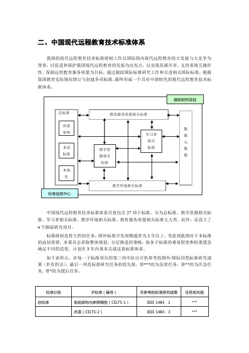
二、中国现代远程教育技术标准体系我国的现代远程教育技术标准研制工作以国际国内现代远程教育的大发展与大竞争为背景,以促进和保护我国现代远程教育的发展为出发点,以实现资源共享、支持系统互操作性、保障远程教育服务质量为目标,通过跟踪国际标准研究工作和引进相关国际标准,根据我国教育实际情况修订与创建各项标准,最终形成一个具有中国特色的现代远程教育技术标准体系。
中国现代远程教育技术标准体系目前包含27项子标准,分为总标准、教学资源相关标准、学习者相关标准、教学环境相关标准、教育服务质量相关标准五大类。
此外,还设立了4个跟踪研究项目。
标准研制是持久性的任务,国外标准开发周期通常为5年以上。
考虑到我国对于本标准的迫切需要,本委员会采取整体规划,分层推进的策略,按各子标准的难易程度和轻重缓急确定不同的进度,计划在3年内基本完成这套标准体系。
如下表所示,在每一子标准项目的第三列中给出可供参考的国外/国际同类标准研究成果(若有的话),最后一列是标准研究任务的优先级,带***的为急需任务,带**的为次急任务, 带*的为缓后任务。
[注1] NIST-ATP/ALSFP: 美国国家标准与技术研究院高科技计划中的自适应学习系统重点项目(Adaptive Learning System Focused Program)标准项目的形式化描述称之为规范,作为标准草案的规范经论证后可作为试用标准,试用标准经过国家信息技术标准化委员会批准后将成为国家标准。
每一子标准研究产生的结果由三部分组成(少数项目例外):(1)规范正文:以简洁的语言对相应的标准做形式化描述,包括标准的目的、作用范畴、术语定义、系统要素和相互关系、元数据定义、数据交换格式等。
(2)实践指南,包含对规范要点的详细解释,并提供如何应用标准的实践范例。
(3)测试规范:描述对用户开发的标准化产品进行测试验证的程序和方法。
由于规范正文是以形式化语言描述的,对于普通用户来说缺乏通俗性,因此建议在阅读规范正文时多加参考相应的实践指南,因为实践指南中包含大量针对标准要点的语义解释和相关应用范例。
测工安全技术操作规程范文

测工安全技术操作规程范文工安安全技术操作规程一、操作人员的安全责任1.操作人员应具备必要的安全意识,严格遵守本单位的安全规定和操作规程。
2.操作人员应熟悉并正确使用所配备的个人防护设备,包括安全帽、安全鞋、口罩等。
3.操作人员应熟悉本单位的事故应急预案,并在发生事故时准确、迅速地采取应急措施。
4.操作人员应随时关注现场的安全状况,如发现异常状况应及时报告相关部门。
二、现场安全管理1.作业前,操作人员应对作业现场进行安全检查,检查内容包括设备设施的安全性、周围环境的安全性等。
2.操作人员必须戴好个人防护设备,并正确佩戴,不得随意取下或调整。
3.操作人员在作业过程中,应注意保持工作场所整洁,不得乱扔垃圾或放置杂物。
4.禁止携带易燃、易爆物品进入作业区域。
5.禁止使用无证或过期的设备进行作业。
6.禁止在无充足照明的环境下进行作业。
7.禁止在设备正在运转中进行维护和修理。
8.禁止在设备上乱丢工具,保持作业区域的整洁。
9.禁止私自更改设备的操作参数或越权操作设备。
10.禁止在设备上或附近吸烟。
三、设备操作安全1.操作人员必须熟悉所操作设备的基本构造和工作原理,并按照操作手册的要求进行操作。
2.操作人员在进行调试或维修设备时,必须确认设备处于停机状态,并采取措施防止误操作。
3.操作人员在操作设备时,应注意观察设备的运行情况,如发现异常应立即停机并报告相关部门。
4.操作人员在设备运转中,不得离开现场,离岗时必须交接班,确保设备的正常运行。
5.操作人员在更换设备部件时,必须关闭设备电源,并采取相应的防护措施。
6.操作人员在设备运转中禁止进行非法操作,如越权操作或违反操作要求。
7.操作人员在设备维修中必须遵守操作规程,使用专用工具,不得使用不当的方法进行维修。
8.操作人员在清洁设备或更换润滑油时,应按照操作规程进行,并注意个人安全。
四、化学品操作安全1.操作人员在操作化学品时,应穿戴好防护用具,如手套、护目镜、防护服等。
测量工、实验工安全操作规程范本
测量工、实验工安全操作规程范本一、目的和适用范围为确保测量工、实验工在工作过程中的安全,并有效预防事故的发生,制定本安全操作规程。
本规程适用于所有从事测量工、实验工的人员,包括但不限于科研人员、实验室技术人员等。
二、一般要求1. 在进行测量工、实验工作前,必须了解和掌握相关实验室安全规定,并参加必要的安全培训。
2. 执行测量工、实验工作时,必须戴上相关的个人防护装备,如安全帽、防护眼镜、防护手套等。
3. 测量工、实验工作场所必须保持整洁、干燥,杂物必须及时清理。
4. 实验室内必须配备灭火器材,并定期检查和维护。
5. 操作人员必须按照实验室的规定和要求进行工作,不得私自更改操作程序和方法。
三、化学实验操作规程1. 在进行化学实验时,必须穿戴好防护服,并将实验室内的通风设施打开。
2. 操作时必须佩戴防护眼镜、手套等个人防护装备,严禁赤手操作。
3. 在操作有毒物质时,必须佩戴好呼吸器具,并遵循正确的使用方法。
4. 混合化学药品时必须谨慎操作,避免发生反应太快导致事故。
5. 操作结束时,必须将实验台面清理干净,化学废品必须妥善处理。
四、电子实验操作规程1. 操作人员在进行电子实验时,必须戴好地气防护手套,并遵循正确的操作流程。
2. 在进行电路测试时,必须事先确认电源已关闭,并使用绝缘工具进行操作。
3. 在进行高压实验时,必须佩戴好绝缘鞋,并严格按照安全操作规程进行。
4. 操作人员在进行焊接作业时,应确保操作区域通风良好,严禁使用易燃物质。
五、机械实验操作规程1. 操作人员在进行机械实验时,必须穿戴好安全帽、防护鞋等个人防护装备。
2. 使用机械设备时,必须进行仔细检查,确保设备完好无损。
3. 操作人员在使用机械设备时,必须站稳并确保周围没有其他人员。
4. 进行机械实验时,必须按照操作规程进行,不得随意调节设备参数。
六、火灾事故应急处理1. 如发生火灾事故,应立即按下火灾报警器,并向相关人员发出警报。
2. 尽快疏散人员,确保安全通道畅通。
试验工安全操作规程范文
试验工安全操作规程范文一、目的和适用范围本规程旨在确保试验工作的安全进行,保护试验人员的身体健康和生命安全。
适用于所有试验工作人员。
二、试验前的准备工作1. 在进行试验前,试验人员必须了解试验内容和试验设备的特点和操作要求,并参照相应的操作手册进行操作。
2. 检查试验设备的工作状态,确保设备完好、无异常,并及时报告维修部门进行维修或更换。
3. 检查试验场地的环境,确保场地干燥、通风良好,并清理场地上的杂物和液体。
4. 检查试验工具和器材,保证其完整、无损坏,并进行必要的清洗和消毒。
三、试验操作要求1. 在进行试验前,试验人员必须佩戴个人防护用品,如安全帽、安全鞋、防护眼镜等,确保自身的安全。
2. 进入试验现场前,必须按照规定的通道和通道标志进行进入,并严格遵守现场指挥员的指示。
3. 在进行试验操作时,应按照试验设备的工作程序和操作步骤进行,严禁违规操作和随意调整试验设备的参数。
4. 在试验设备运行过程中,发现设备异常或存在安全隐患时,应立即停止试验并向现场指挥员报告。
5. 在试验过程中,试验人员应保持冷静、集中注意力,严禁违反操作规程引发事故。
6. 在进行试验操作时,应注意设备周围的安全防护措施,严禁私自接触和操作无关试验设备。
7. 试验人员应随时保持与现场指挥员和其他试验人员的沟通联系,便于及时解决问题和协同作业。
四、应急处理和事故预防措施1. 在试验过程中,如发生设备故障、异常情况或其他突发事件时,试验人员应立即采取紧急停止或疏散措施,并报告现场指挥员和维修部门进行处理。
2. 在试验现场应设置相应的安全警示标志和应急设备,并定期检查和维护,确保其可用性。
3. 试验人员应定期进行安全培训和演练,提高应急处理能力和事故预防意识。
4. 如发生事故,试验人员应立即报告现场指挥员和安全主管,并配合相关部门进行事故调查和处理。
五、试验后的操作要求1. 试验结束后,试验人员应及时清理试验现场和工具设备,并归还相关器材和用品。
测工安全技术操作规程范本
测工安全技术操作规程范本第一章总则第一条为了保障员工的人身安全和健康,维护企业的正常生产秩序,根据国家有关法律法规和标准,制定本规程。
第二条本规程适用于本企业生产、作业、施工等各类工作环节中的安全技术工作。
第三条本规程由安全技术管理部门负责制定和管理,并定期进行修订和更新。
第四条本规程实施前,应进行全员培训,确保员工理解并遵守规程内容。
第二章安全准备工作第五条在任何工作开始之前,必须进行安全准备工作。
第六条安全准备工作包括:1.安全防护设施的设置与检查,确保其正常运行;2.确认工作区域内是否有可燃物、易爆物等危险物质,必要时采取相应的防护措施;3.检查工作用具、设备的使用状况,确保其完好并经过维护;4.检查工作场所及其周边环境的安全情况,清除可能存在的安全隐患;5.通知相关人员,确保所有参与人员都有清晰的工作安排。
第三章安全工作操作规程第七条按照作业内容的不同,制定相应的安全工作操作规程,明确防护措施、操作流程、应急措施等。
第八条安全工作操作规程应包括:1.防护措施:明确工作中需要使用的防护设备和安全装置,如安全帽、防护服、防护眼镜等;2.操作流程:详细描述工作操作的步骤、顺序及注意事项;3.应急措施:列出可能发生的危险情况及应对方法,包括如何避免事故、如何报警、如何进行初步的应急处理等;4.禁止事项:明确禁止在工作中进行的不安全行为,如吸烟、饮食、闲聊等。
第四章安全检查和监督第九条安全技术管理部门应定期对工作环节进行安全检查和监督。
第十条安全检查和监督包括:1.检查各项安全措施的设置和执行情况,如防护设施、防护装置、安全标识等;2.检查工作场所的卫生和整洁情况,清除可能存在的安全隐患;3.监督工作人员是否按照规程操作,督促其正确使用防护设备;4.发现问题及时纠正,确保工作安全进行。
第五章记录和培训第十一条每次工作完成后,应当对工作进行记录,包括工作内容、使用的设备和工具、使用的防护措施等。
第十二条定期组织员工进行安全技术培训,提高员工的安全意识和技能。
新国标GBT34657交流充电桩互操作性测试方案解读
新国标GB/T 34657交流充电桩互操作性测试方案解读《GB/T 34657。
1—2017 电动汽车传导充电互操作性测试规范第1部分:供电设备》、《GB/T 34657。
2-2017 电动汽车传导充电互操作性测试规范第2部分:车辆》已经于2018年5月份正式实施,电动汽车及充电桩行业具备一个详细的测试标准,在新测试标准的监督下电动汽车与充电桩的兼容匹配性将会大大提高.本文将为解读新国标GB/T 34657.1交流桩互操作性测试。
一、测试项目《GB/T 34657。
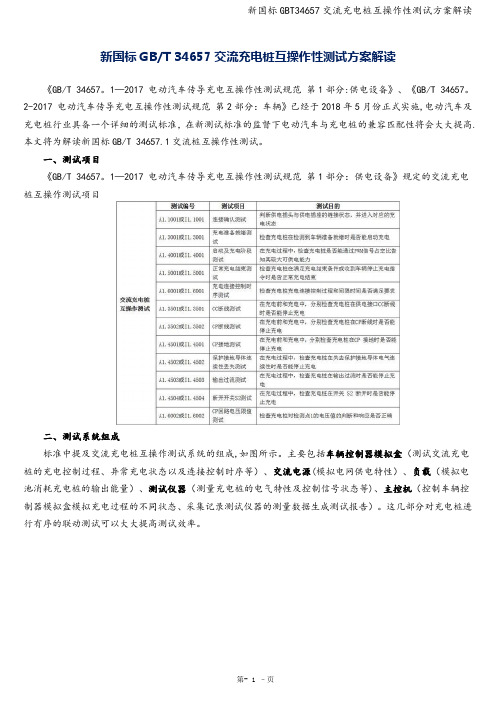
1—2017 电动汽车传导充电互操作性测试规范第1部分:供电设备》规定的交流充电桩互操作测试项目二、测试系统组成标准中提及交流充电桩互操作测试系统的组成,如图所示。
主要包括车辆控制器模拟盒(测试交流充电桩的充电控制过程、异常充电状态以及连接控制时序等)、交流电源(模拟电网供电特性)、负载(模拟电池消耗充电桩的输出能量)、测试仪器(测量充电桩的电气特性及控制信号状态等)、主控机(控制车辆控制器模拟盒模拟充电过程的不同状态、采集记录测试仪器的测量数据生成测试报告)。
这几部分对充电桩进行有序的联动测试可以大大提高测试效率。
图1、交流充电桩交流充电检测系统群菱能源新国标的技术要求推出便携式交流充电桩互操作测试设备 ACTE-2240H ,设备采用6U标准模块化设计,可安装于便携箱,现场测试方便快捷;满足GB/T 34657.1-2017 《电动汽车传导充电互操作性测试规范第1部分:供电设备》标准要求,包括连接确认测试、充电准备就绪测试、启动及充电阶段测试、正常充电结束测试、充电连接控制时序测试、CC断线测试等交流充电桩互操作测试内容;设备可以实现充电电压、电流、功率、CC阻值、充电状态实时监控。
图2、ACTE-2240H 交流充电桩交流充电测试系统结构ACTE-2240H 交流充电桩互操作测试设备带有63A标准交流充电枪插座,插座定义满足GB/T 20234。
USB2.0互操作性测试规范

Universal Serial BusImplementers Forum Full and Low Speed Electrical andInteroperability Compliance Test Procedure *High Speed Electrical Test Procedures AreDocumented SeparatelyRevision 1.3February 2004Revision HistoryRev Date Filename CommentsPosted V1.3 as RC candidate for public review1.3RC1 January2004 USB-IFTestProc1_3RC1.DOC1.3 September 2003 USB-IFTestProc1_3.DOC Update document to new Gold Tree.Removed Windows98SE test procedure sectionsAdded Contact Info, Section A.3procedure for Re-enumerating Devices in Device 1.2.1 27-NOV-2002 USBIF-TestProc1_2.DOCAddedFramework Testing. Added procedure to measure “NotConfigured” current for devices with two-step Full speed toHigh Speed enumeration processes. Changed Back-voltage test to include “All” devices.procedures for using HSET. Updated graphics 1.2 26-AUG-2002 USBIF-TestProc1_2.DOCCorrectedto include 5-hub test environment. Replaced CHUBreferences with HS Gold Tree hub. Added ATEN andIOGEAR “gold” hub to gold tree descriptions. Cleaned upback-voltage section.electrical procedures to use USBHSET instead ofUpdated1.1 15-APR-2002 USBIF-TestProc1_1.DOCUSBCHECK, revised interoperability procedures for HighSpeed devices and added WIN XP as an OS choice1.0 4-DEC-2001 USBIF-TestProc1.DOC Updated for High Speed Gold Tree, added USBCVproceduresremove unconfigured average current test from1.0rc3 30-JAN-2001 USBIF-TestProc1rc3.DOCInteroperability test sections (collect information duringDevice Framework test)1.0rc2 12-JAN-2001 USBIF-TestProc1rc2.DOC add Compliance Page URL1.0rc1 10-DEC-2000 USBIF-TestProc1rc1.DOC incorporate latest comments0.9 15-MAY-2000 USBIF-TestProc09.DOC release for public review0.9rc1 14-MAY-2000 USBIF-TestProc09rc1.DOC incorporate latest commentsincorporate comments following March Plugfest0.9rc 1-MAY-2000 USBIF-TestProc09rc.DOCincorporate comments from Kosta Koeman0.7f 27-MAR-2000 USBIF-TestProc07f.DOCsimplify icons in drawings to save space0.7e 10-MAR-2000 USBIF-TestProc07e.DOCadd drawings and section details0.7d 9-MAR-2000 USBIF-TestProc07d.DOCincorporate comments & section details0.7c 4-MAR-2000 USBIF-TestProc07c.DOC0.7b 27-FEB-2000 USBIF-TestProc07b.DOC continue to add section details0.7a 26-FEB-2000 USBIF-TestProc07a.DOC add figures and section detailsdraft0.7 20-FEB-2000 USBIF-TestProc07.DOCInitialDISCLAIMER OF WARRANTIESTHIS SPECIFICATION IS PROVIDED “AS IS” AND WITH NO WARRANTIES OF ANY KIND, EXPRESS OR IMPLIED, INCLUDING, WITHOUT LIMITATION, NO WARRANTY OF NONINFRINGEMENT, NO WARRANTY OF MERCHANTABILITY, NO WARRANTY OF FITNESS FOR A PARTICULAR PURPOSE, NO WARRANTY OF TITLE, AND NO WARRANTY ARISING OUT OF ANY PROPOSAL, SPECIFICATION, OR SAMPLE, ALL OF WHICH WARRANTIES ARE EXPRESSLY DISCLAIMED.WITHOUT LIMITING THE GENERALITY OF THE FOREGOING, USB-IF AND THE AUTHORS OF THE SPECIFICATION DO NOT WARRANT OR REPRESENT THAT USE OF THE SPECIFICATION WILL NOT INFRINGE THE INTELLECTUAL PROPERTY RIGHTS OF OTHERS. USERS OF THE SPECIFICATIONASSUME ALL RISK OF SUCHINFRINGEMENT, AND AGREE THAT THEY WILL MAKE NO CLAIM AGAINST USB-IF OR THE AUTHORS IN THE EVENT OF CLAIMS OF INFRINGEMENT.USB-IF IS NOT LIABLE FOR ANY CONSEQUENTIAL, SPECIAL OR OTHER DAMAGES ARISING OUT OF THE USE OF THE SPECIFICATION.LICENSE FOR INTERNAL USE ONLYUSB-IF HEREBY GRANTS A LICENSE TO REPRODUCE AND TO DISTRIBUTE THIS SPECIFICATION FOR INTERNAL USE ONLY. NO OTHER LICENSE, EXPRESS OR IMPLIED, BY ESTOPPEL OR OTHERWISE, IS GRANTED HEREWITH, AND NO LICENSE OF INTELLECTUAL PROPERTY RIGHTS IS GRANTED HEREWITH.All product names are trademarks, registered trademarks, or servicemarks of their respective owners.Please send comments via electronic mail to: techsup@USB-IF Full and Low Speed Compliance Test Procedure©Copyright 2000-2003, USB Implementers Forum, Inc.All rights reserved.Table of ContentsIntroduction (vi)Purpose (vi)Scope (vi)A Test Procedure Scenarios – All tests....................................................................A-1 A.1Identify System, Hub, or Peripheral as Unit Under Test...........................................A-1 A.2Required Tests..........................................................................................................A-2 A.2.1Add-in Cards, Motherboards, and Systems..............................................................A-2 A.2.2Full Speed Hubs........................................................................................................A-2 A.2.3High Speed Hubs......................................................................................................A-2 A.2.4High Speed Peripherals............................................................................................A-2 A.2.5Full Speed Peripherals..............................................................................................A-2 A.2.6Low Speed Peripherals.............................................................................................A-3A.3Contacting the USB-IF..............................................................................................A-3B Electrical Tests........................................................................................................B-1 B.1Required Equipment and Equipment Setup..............................................................B-1 B.1.1'Special' items (test fixtures) to be acquired* through Tektronix or Agilent...............B-1 B.1.2standard test equipment............................................................................................B-3 B.1.3standard/available USB products..............................................................................B-3 B.1.4General Equipment Setup.........................................................................................B-3 B.2Host or Hub Power Provider (Droop/Drop) Testing................................................B-10 B.2.1Equipment Used......................................................................................................B-10 B.2.2Drop Testing............................................................................................................B-10 B.2.3Droop Testing..........................................................................................................B-13 B.2.4Reporting Results....................................................................................................B-16 B.3Host Downstream Signal Quality Testing...............................................................B-17 B.3.1Equipment Used......................................................................................................B-17 B.3.2Equipment Setup for testing Downstream Traffic...................................................B-17 B.3.3Signal Integrity Test - Downstream Signal test.......................................................B-17 B.3.4Reporting Results....................................................................................................B-21 B.4Inrush Current Testing............................................................................................B-22 B.4.1Equipment Used......................................................................................................B-22 B.4.2Equipment Setup.....................................................................................................B-22 B.4.3Test Steps...............................................................................................................B-23 B.4.4Reporting Results....................................................................................................B-23 B.5Hub Downstream Signal Quality Testing................................................................B-24 B.5.1Equipment Used......................................................................................................B-24 B.5.2Equipment Setup for testing Downstream Traffic...................................................B-24 B.5.3Signal Integrity Test - Downstream Signal test.......................................................B-24 B.5.4Reporting Results....................................................................................................B-27 B.6Upstream Signal Quality Testing............................................................................B-28 B.6.1Equipment Used......................................................................................................B-28 B.6.2Equipment Setup.....................................................................................................B-28B.6.3Test Steps...............................................................................................................B-29B.6.4Reporting Results....................................................................................................B-33C Device Framework Testing....................................................................................C-1 C.1Equipment Used........................................................................................................C-1 C.2Equipment Setup.......................................................................................................C-2 C.2.1Prepare the Host System..........................................................................................C-2 C.3Test Steps.................................................................................................................C-2 C.3.1All Devices................................................................................................................C-2 C.3.2Re-enumerating Devices...........................................................................................C-7 C.3.3Non-Hub Devices......................................................................................................C-8 C.3.4Hubs........................................................................................................................C-10 C.3.5Hubs with Embedded Devices................................................................................C-13 C.3.6All Devices – Measure “Not Configured” and “Configured” Average Current Draw C-14C.4Reporting Results....................................................................................................C-16D Windows 2000 and Windows XP Peripheral Interoperability Testing...............D-1 D.1Equipment Used........................................................................................................D-2 D.1.1Equipment Setup.......................................................................................................D-4 D.2Software Used...........................................................................................................D-4 D.2.1Software Logistical Overview....................................................................................D-4 D.2.2Install Windows 2000 Professional or Windows XP Professional............................D-5 D.3Initialize the Gold Tree..............................................................................................D-5 D.4Interoperability Logistical Overview..........................................................................D-7 D.5Interoperability Test Steps........................................................................................D-8 D.5.1Device Interoperability...............................................................................................D-8 D.5.2Hub Interoperability.................................................................................................D-31 D.6Measuring Average Current Draw..........................................................................D-42 D.7Reporting Results....................................................................................................D-44D.7.1Interoperability Results............................................................................................D-44E Windows 2000 or Windows XP Host Interoperability Testing..........................E-47 E.1.1Functionality Procedure..........................................................................................E-48 E.1.2S0 Interoperability...................................................................................................E-49 E.1.3S1 Interoperability...................................................................................................E-51 E.1.4S3 Interoperability...................................................................................................E-52E.1.5S4 Interoperability...................................................................................................E-54F Back-voltage Testing...............................................................................................F-1 F.1Equipment Used.........................................................................................................F-1 F.2Which Devices Must Perform the Back-voltage Test.................................................F-2 F.3Test Steps..................................................................................................................F-3IntroductionThe USB-IF Full and Low Speed Electrical and Interoperability Compliance Test Procedure is developed by the USB 2.0 Compliance Committee under the direction of USB-IF, Inc. In addition to other requirements, products must pass the compliance test procedure defined in this document in order to be posted on the USB-IF Integrators List and use the USB-IF logo in conjunction with the said product (if the vendor has signed the USB-IF Trademark License Agreement).PurposeThe USB-IF Full and Low Speed Electrical and Interoperability Compliance Test Procedure documents a series of tests used to evaluate USB peripherals, On-The-Go devices, and systems operating at full speed and/or low speed. These tests are also used to evaluate the full and low speed operation of USB silicon that has been incorporated in ready-to-ship products, reference designs, proofs of concept and one-of-a-kind prototypes of peripherals, add-in cards, motherboards, or systems.ScopeThe procedures documented here address the compliance of the three groups listed by applying the test procedures identified with each group:•Add-in cards, motherboards, and systemso Power Provider (Droop/Drop) testingo Downstream Signal Qualityo Interoperability•Full speed and low speed hubs (no high speed support)o Power Provider (Droop/Drop) testingo Downstream Signal Qualityo Upstream Signal Qualityo Device Framework Testing (Chapter 9 and Chapter 11 compliance)o Interoperabilityo Average Current Consumption•Full speed or low speed peripherals.o Upstream Signal Qualityo Device Framework Testing (Chapter 9 compliance)o Interoperabilityo Average Current Consumption•High Speed Peripherals and High Speed Hubso Interoperabilityo High Speed Electrical Tests documented separatelyEach test scenario shows the specific list of equipment used in the procedure, the initial equipment setup required, the individual steps used to run the procedure (including any equipment reset that is required between devices), and how the results are reported.A Test Procedure Scenarios – All testsA.1 Identify System, Hub, or Peripheral as Unit Under TestCollect the following information before running any tests for later reporting.1.Device: name of the unit under test2.Device Description: describe the unit under test3.Test Suite: identify the test suite or test station – this identification shall uniquely identify theequipment used for the testing should results need to be reproduced.4.Date Tested: range of testing dates5.Test Type: system or hub or peripheral6.Device Category: system or hub or peripherala)System – no further itemsb)Huba.Device Design: no microcontroller (i.e. silicon), microcontroller with USB drivers onsame chip, or microcontroller with USB drivers on different chipb.Power: bus-powered, self-powered, or bothB connection: captive cable or standard cable with A and B plugsd.Drivers: shall test with those provided by operating systeme.Speed: High Speed or Full Speedc)Peripherala.Device Design: no microcontroller (i.e. silicon), microcontroller with USB drivers onsame chip, or microcontroller with USB drivers on different chipb.Power: bus-powered, self-powered, or bothc.Drivers (source of drivers): device vendor, operating system, or third partyB connection: captive cable or standard cable with A and B plugse.Speed: High Speed, Full-speed or Low-speed7.Test Suite Passed: this is determined after all appropriate test have been runA.2 Required TestsCompliance testing requires that the unit under test pass all test procedures listed for its category.A.2.1 Add-in Cards, Motherboards, and Systems• B.2 Host or Hub Power Provider (Droop/Drop) Testing• B.3 Host Downstream Signal Quality Testing•One or more Host Interoperability Testing procedures. These test procedures are operating system specific – a host may be submitted for testing with multiple operating systems; passingany host interoperability test procedure is sufficient for this portion of compliance testing.A.2.2 Full Speed Hubs• B.4 Inrush Current Testing• B.6 Upstream Signal Quality Testing• B.2 Host or Hub Power Provider (Droop/Drop) Testing• B.5 Hub Downstream Signal Quality Testing (Eye pattern testing on hub downstream ports is for informational purposes only. EOP dribble, an allowable distortion of the last bit before thehub EOP, will cause Matlab USB script failures even though the signal quality is withinallowable limits. This is a limitation of the software and should not reflect on the overall testresult for the hub.)• C. Device Framework Testing•H. Back-voltage Testing•One or more Device Interoperability Testing procedures. These test procedures are operating system specific – a hub may be submitted for testing with multiple operating systems; failing any interoperability test procedure causes the hub to fail compliance testing.A.2.3 High Speed Hubs•All Full Speed Hub Tests•High Speed Electrical Tests documented elsewhere.A.2.4 High Speed Peripherals•All Full Speed Peripheral Tests•High Speed Electrical Tests documented elsewhereA.2.5 Full Speed Peripherals• B.4 Inrush Current Testing• B.6 Upstream Signal Quality Testing• C. Device Framework Testing•H. Back-voltage Testing•One or more Device Interoperability Testing procedures. These test procedures are operating system specific – a device may be submitted for testing with multiple operating systems; passing any interoperability test procedure is sufficient for this portion of compliance testing.A.2.6 Low Speed Peripherals• B.4 Inrush Current Testing• B.6 Upstream Signal Quality Testing• C. Device Framework Testing•H. Back-voltage Testing•One or more Device Interoperability Testing procedures. These test procedures are operating system specific – a device may be submitted for testing with multiple operating systems; passing any interoperability test procedure is sufficient for this portion of compliance testing.A.3 Contacting the USB-IFFollowing is a list of email addresses into the USB-IF organization. Since the USB-IF is a collaborative effort, these addresses are monitored by key individuals of several member companies.If you are not sure which email address to use, or the information is confidential, send toAdmin@ and they will forward your email to the appropriate person or group.Admin@ Primary contact address of the USB-IF. Handles all administrative, workshopand tradeshow logistics, registration, licensing, USB-IF website, logoadministration and legal issues.TechSup@ Technical support on test procedures, specification clarifications, “how to” and general help.TechAdmin@ Certification issues, workshop questions, reporting bugs in USB-IF tools anddocumentation.CRB@ Waiver requests onlyB Electrical TestsB.1 Required Equipment and Equipment SetupThe following items are used.Note that the equipment listed, the test procedure steps, and the actual list of required tests is expected to change. Please refer to /developers/complian.html on the USB-IF, Inc. web site for the latest version of this document.B.1.1 'Special' items (test fixtures) to be acquired* through Tektronix or Agilent.item description/model qty 100mA Load Board* 1500mA Load Board* 1Droop Test Board* 1SQiDD Board* Signal Quality, Inrush and Droop/Drop test jig 15V power supplys (for HUBs) 6**FS Hub (Self-powered) Belkin F5U100 / F5U101 16**HS Hub (Self-powered) APC 19500SG-1G or IO Gear Model GUH-224 ‘Gold’ orany certified high-speed hub*At the time of the latest update of this document these test fixtures were available through Tektronixand Agilent.** a 6th unit is recommended as a spareFigure B-1: SQiDD BoardThe Signal Quality Droop Drop or SQiDD board is divided into three sections; Section 1 has AA signal and power break monitor points together with an Inrush Current switch and V BUS current monitor loop. Section 2 only has AA signal and power break monitor points. Section 3 has BB signal and power break monitor points together with an Inrush Current switch and V BUS current monitor loop.All three sections of the SQiDD board are used for signal quality testing and support multiple Oscilloscope probe types. The Tektronix P6204/5 Oscilloscope probe types are obsolete. These probes are only suitable for low- and full-speed signal quality testing. A header for a newer type probe is used as the default Signal Quality Probe point. This header supports new type probes like the Tektronix P6243 and P6245 probes which offer limited ability to probe high-speed (USB 2.0) signaling environments.Two sections, 1- AA and 3- BB, of the SQiDD board are also used for Inrush and Power Testing with wire loops that are used with Clamp on type current probes. Added power switch functions support Inrush testing on these two sections. A three-position switch has a normal powered mode as its default which passes V BUS straight through. Switch position 2 shorts out and discharges the V BUS and Ground rails of the Device Under Test (DUT) or Hub Under Test (HUT) through a 1 KΩ resistor. Switch position 3 opens theV BUS line and allows for hooking up the DUT or HUT and current probe.B.1.2 standard test equipmentitem description/model qty oscilloscope Tektronix TDS 684C or 784C * 1 TDS Probes P6245 voltage probes (or equivalent)** 3 Current ProbeTCP202 current probe1multimeter Keithley 2000 Multimeter 1 USB Host System with GPIB board/controllerHardware Configuration:815EEA2 motherboard, Pentium III 700 mHz, 256meg ram, 40g HD, CD (or CD/RW), FDIOGear (or ATEN) USB 2.0 PCI Card (5-port) Model GIC250UNational Instruments I-488.2 GPIB support for connection to 'oscilloscope'1* supported by available GPIB data aquisition scripts – other models may require extensive script modifications to properly interface with the GPIB DAQ application.**Do not use P6249 voltage probes since they do not have adequate dynamic voltage range.B.1.3 standard/available USB productsitem description/model qty Isoch Device any listed on USB-IF Full-speed PC Camera 1 mouseany listed on USB-IF mouse8 one meter USB cables any listed on USB-IF Cables and Connectors Integrators List3 five meter USB cablesany listed on USB-IF Cables and Connectors Integrators List6B.1.4 General Equipment SetupB.1.4.1 OscilloscopeThe following section defines the test equipment setup and operational requirements. Refer to the equipment list items for setting up equipment. Follow the step-by-step instructions to set up the oscilloscope setups for Signal Quality testing.Scopes from various manufacturers are capable of the required test operation. However, the currently available MatLab scripts support the Tektronix model TDS 684C and 784C oscilloscope. Using other models may require extensive script modifications.Each setup command that starts with one of the main buttons on the scope’s front panel is marked with a bullet, with subsequent selections being made on the horizontal and vertical rows of buttons next to the scope’s display. If multiple selections in a row are made from one main menu, the subsequent selections are indented below the bulleted one according to how far down they are in the submenus. For some selections, you’ll need to scroll through the menu at the right side of the scope’s display to find them. Depending on the model of TDS, the exact horizontal division settings, record lengths, and triggerpositions may vary. If a wrong initialization step was taken, the test operator can start over from the last point at which a setup was saved by recalling that setup: setup →recall setup →setup n .These setup steps may need some customization for a given measurement:•Depending on the amount of data returned or sent on the bus, the signal integrity setups may need adjustments to trigger positioning, record length, and the horizontal division size. Try to keep the horizontal division size @ 50 points/division close to 200ns/division for LS signals and 25 or50ns/division for FS.•The inrush setups will need a lot of adjustment, as inrush currents manifest a wide variety of durations and peak currents. Expect to use vertical division settings anywhere from 100mA/division to 5A/division and timebases between 500ns/div and 20µs/division. If you need a timebase longer than 20µs/division, it’s usually best to max out the scope’s record length before upping the timebase. The oscilloscope is used as the front-end capture of data that is transferred to the PC to be further analyzed, documented and saved in soft data format. This process uses the National Instruments GPIB board to transfer instrumentation data from the oscilloscope to the PC. Data point analysis is done with MatLab analysis software using specific MatLab scripts. The GPIB board and its associated software is installed in the PC.All of the setups split the oscilloscope’s trace display into two areas. The upper one is a zoom window that shows the contents of the box shown in the lower widow. The lower window shows the entire contents of the oscilloscope’s records (except for 15k point records, where it only shows two thirds of the record at any given time for reasons known only to Tektronix). This setup is handy for looking at any individual part of the captured waveform. You can move the box around with the horizontal and vertical position knobs as long as the upper graticule is active (it’s selected with zoom→graticule→upper), though it’s usually more convenient to do one’s zooming in MatLab. If you need to work with the lower graticule, select it (zoom→graticule→lower), and do whatever it is that needs to be done.In addition, all of the setups use gated, paired cursors. The paired bit means the scope puts markers on the currently selected channel where it crosses the cursors and gives you X and Y deltas between the markers. This comes in handy occasionally. The gated bit means that the measurements the oscilloscope (rise/fall time, mean, max, etc.) makes are done on the part of the record between the two cursors. This lets you gate out a particular part of the record that’s interesting and take measurements for just that part of the record, rather than having the scope indiscriminately apply the measurements to the entire record. Generally, though, it’s faster and more convenient to look at the eye diagram in MatLab or zoom in on MatLab’s plot of the scope data.B.1.4.1.1 Tips on Using the Scope•Pressing shift activates Coarse Knobs, which increases the effect of anything you twirl. This is really handy for moving cursors and the zoom window around. Pressing shift again will turn coarse knobs off.•The “I” shaped bar above the upper graticule represents the entire contents of the oscilloscope’s records. The brackets indicate the area of the record is displayed in the lower graticule. The T marks the trigger point’s position in the record, and the dashed and solid lines mark the positions of the inactive and selected cursors, respectively.B.1.4.1.2 Initial Scope SetupNote: step 2 requires a minimum one hour for scope warm up before completing the initial scope setup procedure.1.Refer to the instrument's user guide for initial probe compensation settings.。
中国网络教育技术标准(CELTS)体系介绍

CELTS系列标准培训 2006.1
基于规则的XML绑定技术
(CELTS-4 )
规定了将网络教育技术标准的信息模型做 XML编码绑定的方法。 指导标准制订者制订网络教育技术标准的 相应XML 绑定规范和实践指南。
8
CELTS系列标准培训 2006.1
学习资源类
通用规范 学习对象元数据规范 (CELTS-3,CD2.0) 专用规范 教育资源建设规范 (CELTS-41,CD1.6) 基础教育资源元数据应用规范 (CELTS-42,CD1.6) 简单课程编列规范 (CELTS-8,CD1.0) 内容包装规范 (CELTS-9,CD2.0) 测试互操作规范 (CELTS-10,CD2.0)
25
9
CELTS系列标准培训 2006.1
学习对象元数据规范
(CELTS-3)
规定了对学习对象的描述方法。 帮助学习者,教育者或自动化的软件等对 学习对象进行查找、评估、获取和使用。 通过定义一个通用的概念数据模型,本标 准保证学习对象元数据的绑定之间有较高 程度的语义互操作性。这S系列标准培训 2006.1
标准的研究与推广活动
定期召开工作会议 举办研讨与培训 吸收团体会员 开展标准符合性测试与认证 参与ISO JTC1/SC36工作 网站宣传与服务
/
24
CELTS系列标准培训 2006.1
参考文献
CELTS-3系列 标准 现代远程教育 技术规范简介,沈中南 史元春
18
CELTS系列标准培训 2006.1
学力定义 (CELTS-14)
定义了一个普遍适用的学力信息模型。
学力,是描述学习者能力水平的信息。
为学力的含义提供通用的理解,描述了不同层次 的学力所应该具有的表现。 目的:
- 1、下载文档前请自行甄别文档内容的完整性,平台不提供额外的编辑、内容补充、找答案等附加服务。
- 2、"仅部分预览"的文档,不可在线预览部分如存在完整性等问题,可反馈申请退款(可完整预览的文档不适用该条件!)。
- 3、如文档侵犯您的权益,请联系客服反馈,我们会尽快为您处理(人工客服工作时间:9:00-18:30)。
CELTS-10:练习/测试互操作规范
(一)本规范的目的
现有题库系统因为没有统一的标准格式,各系统间不能实现有效的共享,并严重依赖于
特定的学习支撑环境和教学平台,形成自成体系的信息孤岛,导致了低水平的重复开发,浪
费了大量的人力物力;而封闭运行使得题库无法得到广泛的普及,无法真正在教学过程中发
挥其应有的作用,无法得到广泛的使用和参与,从而使得题库的修订和校正缺乏数据基础,
难以提高整个题库数据的质量。
总之,由于练习、测试、结果报告以及属性等表示结构的多
样性,导致了练习/测试数据不能满足资源的互操作性、长期性、可获得性、可扩展性和可
重用性等。
练习/测试互操作规范主要解决目前练习/测试数据的独享性和缺乏开放性等问题。
支持
题目/测试数据的互换、支持题目/测试结果报告的标准化、支持各类题型、支持对产品进行
标准一致性检测的工具、支持可扩展、支持低费用开发、支持高性能的学习系统。
本规范的
核心目标是为用于现代远程学习的不同系统和用户提供具有互操作性的标准格式的练习/测
试数据。
练习/测试互操作规范不是为了构建一个软件产品,它主要是定义一个支持内容开
发者和服务提供者协同合作、相互通信(即:互操作)的技术规范。
因此在该标准中,我们
希望如果有用户开发了一个极好的内容开发系统,那他就应该可以自由地选择内容分发系统。
该标准解决了“怎样获得互操作性”的问题,如图1所示:
数字信息QTI 规范可复用的标准项、学习对象库传输系统、开发系统等
图1 练习/测试互操作示意图
各种数字信息按照QTI规范提出的信息模型组织成标准的项、学习对象模块,以使得传
输系统、开发系统等可以直接重用、互用不同来源的数字信息。
这也是我们的核心目标:不
同的用户间或不同的系统间就可以互用练习/测试数据!
(二)本规范的主要内容
练习/测试互操作规范的主要用户有内容提供者、学习环境、工具开发者和练习/测试数据的用户等;目标市场包括幼儿教育、基础教育、中等教育、高等教育、培训以及终身教育等。
本规范参照IMS、IEEE、ADL等相关标准,形成ASI信息模型、结果报告信息模型以及XML绑定实例三部分文档草案。
1.ASI信息模型:该模型作为QTI互换模型提供了题库中内容的表现形式和内容组织方法,回答了“如何对已有的内容进行组织描述”的问题。
评估(Assessment)、节(Section)、项(Item)这三个对象结合在一起称为ASI结构。
如图2所示:
图2 ASI信息模型
标准练习类型可使用一系列表现形式和响应类型来构造,且练习结果的采集和计分有多种方法。
该规范定义了“项”以涵盖题目所涉及的以上所有内容。
项包括了练习的表述、构成、计分和反馈等全部信息。
题目和项的主要区别就在于:“项”不仅包括了“题目”本身,还包含显示信息、响应处理信息、提示和解决方案以及反馈等与“题目”相关的信息。
“节”是个聚合概念,是由一个或多个项/节组成的;而“评估”类似于通常意义上的测试,是“节” 的集合。
总之,评估是由一个或多个节组成的,而节又是由一个或多个项/节组成的,ASI
结构定义是递归的。
ASI信息模型具有以下特点:基本ASI 数据定义很简单,但也很灵活,可组成复杂的数据结构;评估数据至少需要包含一个节;评估不能直接包含项;节可嵌套;节可包含一个或多个项;允许定义空节;项是最小的独立单元,能在QTI中互用,不允许项嵌套等。
2.结果报告信息模型:主要描述用户响应结果的信息模型,规范结果报告的格式,基于不同形式的结果报告之间、基于不同平台的结果报告之间能够交互,真正做到评估结果的可比性、可转换性、相对性。
该部分支持ASI信息模型,是对ASI信息模型的补充和完善。
基本信息模型如图3:
图3 结果报告信息模型
其中核心数据结构有:结果、上下文、结果概要、评估结果、节结果和项结果。
结果:实际评估或其他形式评价的结果集。
单个或多个被试者的多个结果被包含在QTI 结果报告封装包中;上下文:有关实际评估的上下文信息,如被试者姓名、被试者标识符等;结果概要:特定评估的总体信息。
每个结果只包含一个总体信息;评估结果:对某一特定评估的详细评估信息。
每一结果只包含一个评估信息(包括评估所包含的节和项);节结果:有关节(已经完成的或将要尝试的)的详细信息。
每一个结果只包含一个节的信息(包括节所包含的节和项);项结果:有关项(已经完成的或将要尝试的)的详细信息。
每一个结果只包含一个项的信息。
3.XML绑定实例:XML的灵活性和扩展性使其可以对不同应用甚至是差异很大的应用间的数据进行描述,尤其是对于那些专用于记录数据的应用。
另外,XML具有自我描述的特性,结果是数据可以在不同的应用间进行交换与处理而不必要求相应的应用程序是针对该数据定制的。
由于XML属于纯文本,因此可以作为与平台无关的数据格式。
它是开放的,能够在不同的用户和程序之间交换数据,而不论其平台如何。
有鉴于此,XML绑定策略提供了一种编码和描述的方法,描述如何用XML实现QTI信息模型,描述文档类型定义(DTD),DTD 被用来为QTI 系统,特别是那些用于分布式学习的QTI 系统提供互操作性。