400W_500W连续光纤激光器说明书_正式
连续光纤激光器使用说明书-杰普特

连续光纤激光器 使用说明书I深圳市杰普特光电股份有限公司II安全信息感谢选用深圳市杰普特光电股份有限公司连续光纤激光器产品!在使用本产品之前,请仔细阅读本使用说明书。
在本使用说明书中我们为您提供了重要的产品安全操作规范及其它参考信息。
为确保您在使用本产品时的人身安全及使本产品发挥最佳使用性能,请在操作中遵循以下注意警告事项及本说明书内的其它操作规范。
•连续光纤激光器是IV级激光产品。
在接入交流电源前,要确保220VAC 电源连接正确,错误连接电源,将会损坏激光器。
•请确保使用带有可靠接地以及过流保护装置的交流电源。
使用时务必保证激光器的可靠接地,以避免可能产生的人身伤害。
•该激光器在 1080nm 波长范围内发出超过 800 瓦的激光辐射。
避免眼睛和皮肤接触到激光输出端直接发出或散射出来的辐射。
•不要打开激光器,因为没有可供用户使用的产品零件或配件。
所有保养或维修工作只能由杰普特专业人员在杰普特公司内进行。
•在操作该机器时要确保全程配戴激光安全防护眼镜。
即使佩戴了激光安全防护眼镜,也严禁直接观看激光输出头。
IIIIII表1激光器安全标签 标签图片标签信息激光标签(位于激光器后面板铠缆输出位上方)安全警告(位于激光器后面板)图 1 激光防护眼镜目录安全信息 (I)图 1 激光防护眼镜 (IV)一、产品信息 (1)1.产品描述 (1)二、配置清单 (2)1.实际配置清单 (2)三、技术参数及安装说明 (3)1.技术参数 (3)2.激光器安装尺寸图 (5)3.激光输出头尺寸图 (5)4.安装方法 (6)四、控制与操作 (11)1.外部接口定义: (11)2.JPT监控软件介绍与安装 (12)IV3.激光器开关光: (15)五、激光器报警及故障现象处理 (18)1.软件日志显示: (18)2.激光器常见报警及警告信息及处理方式: (19)六、激光器质保服务及维修 (22)1.一般保修: (22)2.保修限定 (22)3.服务和维修 (23)V1一、 产品信息1. 产品描述光纤激光器与传统激光器相比,具有电光转换效率高、结构紧凑、免调节维护、光纤柔性传导输出等众多优点,是工业激光切割、焊接及其它应用的理想光源。
新外观W连续光纤激光器说明书文件

C1500W-2200W连续光纤激光器说明书武汉锐科光纤激光技术股份有限公司Wuhan Raycus Fiber Laser Technologies Co., Ltd.目录1安全信息 (3)1.1安全标识 (3)1.2激光安全等级 (3)1.3光学安全 (4)1.4电学安全 (4)1.5其他安全注意事项 (4)2 产品说明 (5)2.1产品特性 (5)2.2实际配置清单 (5)2.3开箱及检查 (5)2.4运行环境 (6)2.5注意事项 (6)2.6产品性能 (7)3安装 (8)3.1安装尺寸图 (8)3.2安装注意事项 (9)3.3冷却系统要求 (11)4产品的使用 (13)4.1前面板 (13)4.2后面板 (14)4.3电源连接 (16)4.4控制接口定义 (17)4.5激光器工作模式及控制模式 (20)4.6控制模式的设置 (21)4.7超级终端模式 (21)4.8 RS-232模式 (27)4.9 AD模式 (30)4.10红光控制 (33)5常见故障及处理措施 (33)5.1故障记录及故障的发生 (33)5.2故障处理 (34)6质保及返修、退货流程 (35)6.1一般保修 (35)6.2保修的限定性 (35)6.3技术支持及产品维修 (36)感谢您选择锐科光纤激光器,本用户手册为您提供了重要的安全、操作、维护及其它方面的信息。
故在使用该产品之前,请先仔细阅读本用户手册。
为了确保操作安全和产品运行在最佳状态,请遵守以下注意和警告事项以及该手册中的其他信息。
1.1安全标识警告注意1.2激光安全等级根据欧洲标准EN 60825-1,条款9,该系列激光器属于4类激光仪器。
该产品发出波长在1080nm或1080nm附近的激光辐射,且由输出头辐射出的平均光功率为1500W~2200W(取决于机器型号)。
直接或间接的暴露于这样的光强度之下会对眼睛或皮肤造成伤害。
尽管该辐射不可见,光束仍会对视网膜或眼角膜造成不可恢复的伤害。
400W-500W连续光纤激光器说明书-正式

连续光纤激光器使用说明书武汉锐科光纤激光器技术有限责任公司安全信息在使用该产品之前,请先阅读和了解这份用户手册并熟悉我们为您提供的信息。
这份用户手册提供了重要的产品操作,安全以及其他信息给您以及所有将来的用户作参考。
为了确保操作安全和产品的最佳性能,请遵循以下注意和警告事项以及该手册的其他信息去操作。
●连续光纤激光器是IV级的激光产品。
在打开220VAC电源前,要确保连接是正确的220VAC的电流,错误连接电源,将会损坏激光器。
● 该激光器在1060~1080nm波长范围内发出超过500瓦的激光辐射。
避免眼睛和皮肤接触到光输出端直接发出或散射出来的辐射。
● 不要打开机器,因为没有可供用户使用的产品零件或配件。
所有保养或维修只能在锐科公司内进行。
● 不要直接观看输出头,在操作该机器时要确保长期配戴激光安全眼境。
安全标识及位置上面二个安全标识符号表示有激光辐射,我们把这符号标在产品光纤盒体盖顶上。
目录1.产品描述 (1)1.1.产品描述 (1)1.2 实际配置清单 (1)1.3 使用环境要求及注意事项 (1)1.4 性能参数 (2)2.安装 (2)2.1 安装尺寸图 (2)2.2 安装方法 (4)3.控制接口与操作 (5)4.质保及返修、退货流程 (11)5.1一般保修 (11)5.2保修的限定性 (11)5.3服务和维修 (12)1.产品描述1.1. 产品描述光纤激光器相对于传统的激光器,能够使每瓦的泵浦光转换效率提高10倍以上,低能量消耗的自动设计,适合实验室或室外操作。
精巧、可独立放置、可随时使用,能够直接嵌入用户的设备上。
1.2 实际配置清单请根据图表1参考所包括的清单。
1.3 使用环境要求及注意事项锐科光纤激光器需使用单相220V±10%、50Hz交流电。
警示:1)使用激光器时要确保可靠接地。
2)没有内置可供使用的零件,所有维修应由锐科人员来进行,为了防止电击,请不要损坏标签和揭开盖子,否则产品的任何损坏将不被保修。
飞博激光 连续光纤激光器 使用手册
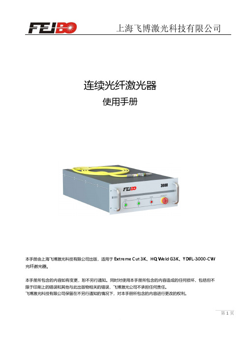
连续光纤激光器使用手册本手册由上海飞博激光科技有限公司出版,适用于Extreme Cut 3K、HQ Weld G3K、YDFL-3000-CW 光纤激光器。
本手册所包含的内容如有变更,恕不另行通知。
同时对使用本手册所包含的内容造成的任何损坏,包括但不限于印刷上的错误和其他与此出版物相关的错误,飞博激光公司不承担任何责任。
飞博激光科技有限公司保留在不另行通知的情况下,对本手册所包含的内容进行更改的权利。
目 录简 介 (3)1. 激光器工作原理及系统组成 (4)2. 激光器外部接口 (4)2.1.交流电源输入接口 (4)2.2.DB9-RS232串行通讯接口 (5)2.3.外部控制信号接口 (6)2.4.激光器水冷接口 (7)2.5.CDA(清洁干燥空气)接口 (9)3. 拆箱、安装、拆装及重包装 (9)3.1.拆箱 (9)3.2.安装 (10)3.3.拆装 (11)3.4.重包装 (11)4. 激光器操作流程 (12)4.1.上电前检查 (12)4.2.激光器的连锁功能及其解除 (13)4.3.输出激光/控制激光功率 (14)4.4.外部光路调整 (16)4.5.中断输出 (16)4.6.关机 (16)5. 激光器维护 (17)6. 激光器故障排除 (17)7. 激光器返厂维修 (19)8. 激光器评估 (20)9. 附件 (21)9.1激光器外型尺寸 (21)9.2内部接口参考电路 (22)简 介感谢选用上海飞博激光科技有限公司(以下简称飞博激光)的连续光纤激光器产品。
本手册中包含了安全操作和维护此激光产品所需的必要信息。
并以下列组织方式进行详细描述:1.激光器工作原理及系统组成;2.激光器外部接口;3.拆箱、安装、拆装及重包装;4.激光器操作流程;5.激光器维护;6.激光器故障排除;7.激光器返厂维修;8.激光器评估;9.附件1)激光器外型尺寸;2)内部接口线路参考;对于本手册中尚未包括的内容,请咨询飞博激光获取进一步信息。
光纤激光器 说明书

此标志代表激光器发光, 我们已经将此标志贴在产品的激光输出端。 一般安全指示 为 了 确 保 产 品 的 安全 操 作 和 最 佳 性 能 , 除了 本 文 档 包 含 的 其它 信 息 外 ,请 遵 守 以 下 WARNING 和 CAUTION。 WARNING:激光器始终在经妥善接地的电源下工作。 CAUTION:在给激光器供电前,请确保 DC 供电电压正确(24VDC))使用, 错误的供电将会引起设备损坏。 WARNING:内部没有操作者可以维修任何的部件,必须要有资格的创鑫激光员工才能 维修。为了避免电路短路,不要打开机壳,对产品进行任何篡改,否则将 不负责保修。 WARNING:此激光器有一个用光纤缆连接的光学输出头。请务必小心处理此输出头。 WARNING:如果此设备在一个本文档没有具体指明的方式下使用,本设备 提供的保护可能会被损坏。此产品必须仅被用在正常的环境下
1. 描述 PDF 文件使用 "pdfFactory Pro" 试用版本创建
-4-
光纤激光器使用说明书
MFP系列脉冲光纤激光器是创鑫激光的尖端产品之一。它的出现对于高速度 、高分辨 率激光打标系统的集成具有革命性意义。 MFP系列的主要优势是超越了传统的二极管泵浦晶体激光器,包括(Nd):YAG激光器。 它使用Q开关(光量开关)主振荡器和高功率光纤放大器(MOPFA)构造。MFP系列功耗 低且实用,耐用的设计,适合于实验室和市场应用。结构紧凑、单机、易于使用的设 计风格,可以直接集成到用户的设备中。 MFP系列激光器发射波长为1060nm左右和峰值功率高达7KW以上的周期性脉冲序列。激 光器的运行参数通过25Pin控制接口进行设定。配上 客 户 的 特殊控制器可以用于手持激光 器。此激光器需要一个外部 DC 供电 。 MFP系列激光器是一个理想的用于激光打标工业的高功率源。 光头带有光隔离器, 可以 直接应用于低反射材料(如塑料、木、纸等等),以及对于金属打标。 2. 附件 请根据下表确认本产品包含的附件: 项目 指导手册和测试结果 供电电源(可选) 3. 供电 MFP系列的供电电压为 24VDC。 电源线颜色 棕色 兰色 黄绿色 电路连接 +24V DC GND 激光器外壳 数量 1 1
IPG光纤激光器说明书
产品质量保证条款谢谢贵公司购买我公司光纤激光器!贵公司需在发货后一个月内确认产品的质量问题,如果不能尽快在一个月内确认的话,就会造成在服务和供货上不必要的麻烦,特别是对于产品不是在美国本土安装的。
我们将给贵公司提供最好的质量和技术支持,在设备的安装和调试操作方面我们有一套详细的方案。
可以通过以下两种途径确认产品的质量:1.将已付资费同时写好地址的信封寄给我方2.直接上网进行确认所有提供的信息都是必须保密的有任何问题可以直接拨打客服电话(508)373-1157安全条款:1.警告鉴于对人体潜在的伤害,请按照规定的程序进行操作,如果不这样做的话,对自己或者他人都会造成伤害2.警示鉴于产品潜在的危险,请按照规定的程序进行操作,如果不这样做的话,对产品自身或者产品的零配件都会有损害3.重要事项关于产品的操作事项请按照说明书逐步操作。
你公司所购买的是400瓦的光纤激光器,执行标准是21 CFR 1040.10,激光波长达到1070纳米,通过光纤输出的激光的功率实际上已经超过400瓦,对人的眼睛和皮肤都会造成伤害,尽管这种辐射是不可见的,但是这种激光对人的角膜的伤害是无法避免的,在设备工作的时候必须带上激光护目镜。
警告:在设备工作中请根据波长范围选择合适的护目镜,请仔细阅读产品上的安全标签,产品的输出功率和波长范围。
有很多供应商为我们提供原材料和零配件。
如果设备经过重新安装或者改进的话,由终端客户负全责。
在设备的调试,操作过程当中如果不按照规定的程序运行,就会造成一定的危害在设备运行过程中,不要随意触动光纤激光器任何部件。
比如光纤准直器。
在靠近激光的位置会从不同的角度发散出激光,这些激光会从不同的镜面物体反射,反射的激光强度都会对人的眼睛和皮肤造成一定的伤害。
激光对人的皮肤,服装都会造成很大的伤害,激光可以引燃比如酒精,汽油之类的溶剂,激光可以进行切割和焊接,在安装和使用设备的时候请谨慎使用一些易燃的材料和气体。
1000W 光纤激光器 使用说明书

1000W光纤激光器使用说明书目录引言 (1)1. 安全与维护 (2)1.1产品安全等级 (2)1.2产品安全及信息标识 (2)1.3产品使用安全与维护 (2)2.产品介绍 (4)2.1产品特性 (4)2.2拆箱及检查 (4)2.3技术参数 (5)2.4配置清单 (6)2.5产品面板说明 (6)2.6控制接口定义说明 (7)2.6.1控制模式 (7)2.6.2控制时序图 (9)2.7供电要求及接线定义 (9)3.安装与开启激光器 (10)3.1整机尺寸 (10)3.2安装注意事项 (11)3.3冷却系统要求 (12)3.4开启与关闭激光器 (13)3.5上位机的使用 (14)4.常见故障及解决措施 (19)5.质保及返修 (20)5.1 一般保修 (20)5.2 保修的限定性 (20)5.3 服务和维修 (20)附表表 1 产品安全及信息标识 (2)表2产品技术参数 (5)表 3 产品面板及定义说明 (6)表 4 RS-232通讯接口定义 (7)表 5 RS-232接口配置参数 (8)表 6 DB25控制接口的接线定义 (8)表7 冷却系统要求 (12)表8 不同环境湿度的结露点 (13)表9激光器的常见故障及解决措施 (19)附图图 1 控制时序图-连续、脉冲 (9)图 2 产品前视图尺寸 (10)图 3 产品后视图尺寸 (10)图4产品俯视图尺寸 (11)图 5 上位机安装 (15)图 6 上位机安装指引 (15)图7 上位机图标 (15)图8 上位机软件中激光器没有连接串口提示 (16)图9 上位机主页面 (16)图10 报警指示灯界面详细信息 (17)图11售后诊断界面 (17)图12 密码输入提示框 (18)引言欢迎您使用天津凯普林光电科技有限公司(以下简称“凯普林光电”或“本公司”)的连续光纤激光器,为了便于您更好地使用激光器,我们特地编制了本使用说明书。
本说明书将为您提供关于本产品的安装、操作与维护信息,请您妥善保管;在安装和使用本产品之前,请仔细阅读本说明书,以了解和熟悉本产品;在安装和使用过程中,请严格按照本说明书中提到的要求和规格进行安装使用,以免引起产品损坏或人身伤害。
锐科光纤激光器-RFL-P500 使用说明书

RFL-P500 Pulsed Fiber Laser User GuideTABLE OF CONTENTS1 Safety Information (1)1.1 Security Warning (1)1.2 Laser Safety Grade (1)1.3 Safety Identification (2)1.4 Optical Safety (3)1.5 Electrical Safety (3)1.6 Other Safety Rules (3)2 Product Description (4)2.1 Features (4)2.2 Package Parts (4)2.3 Unpacking and Inspection (4)2.4 Operation Environment (5)2.5 Attentions (6)2.6 Specifications (6)3 Installation (7)3.1 Dimensions (7)3.2 Dimensions of Output Head (9)3.3 Cooling Requirements (10)4 Using the Product (12)4.1 Front Panel (12)4.2 Rear Panel (13)4.3 Power Connection (14)4.4 Interface Definitions (15)4.4.1 SERVICE (15)4.4.2Control Interface (16)4.4.3 RS-232 Serial Port (19)5 Application Steps of Laser Device (20)5.1 Pre-inspection (20)5.2 Operational Steps (20)5.3 Attention in the process of operation (21)6 Common Alarms and solutions (21)7 Warranty, Return and Maintenance (22)7.1 General Warranty (22)7.3 Service and Repair (23)1Safety InformationThank you for choosing Raycus fiber laser. This User Guide provides important safety, operation, warranty and other information. Please read it carefully before use this product. In order to ensure safe operation and optimal performance of the product, please follow the warnings, cautions, operating procedures and other instructions accordingly.1.1Security WarningWARNINGCAUTION:product damage.1.2Laser Safety GradeAccording to the European Community standards EN 60825-1, clause 9, this series of lasers are classified as a high power Class 4. This product emits invisible laser radiation at wavelength of 1064 nm, and the maximum power is 500W. Direct or indirect exposure of high power of laser radiation may cause damage to the eyes or skin. Despite the radiation being invisible, the beam may cause irreversible damage to the retina and cornea. Appropriate and approved laser goggles must be worn all the time during the laser device is operating.WARNING:thiswavelength emitted from this product. Users must ensure that the pretectrange of laser goggles over the entire range of laser wavelengths. Pleasedo not directly view the laser output head when laser emitting.1.3Safety IdentificationFigure 1 : Safety identification positionTable 1: Safety identificationEnglish Label Chinese Lable English Label(500W)Chinese Lable(500W)English LabelChinese Lable1: Laser Emit Head 2: Type 4 Laser Product 3: Class 2M Laser Product Label-2mW Red Laser4:CE Label 5: Electrical Hazard 6: ID Label1.4 Optical SafetyAny dust on the end of the collimator assembly can burn the lens and damage the laser device.CAUTION:otherwise the lens or crystal will be damaged.1.5 Electrical Safetya) Ensure the product is grounded through the PE line of the AC power cord. The grounding must be firm and reliable.WARNING: the enclosure, which may result in personal injury.b) Ensure that the AC voltage is supplied normally.CAUTION:un recoverable damage to the laser device.1.6 Other Safety Rulesa) Do not directly view the laser output head when laser emitting. Avoid usingthe laser in a dark environment.b) Do not use fiber lasers in dark environments.c) If this device is used in a manner not specified in this document, theprotection provided by the device may be impaired and the warranty will be voided.d) There are no user serviceable parts, equipment or assemblies inside theproduct. All service and maintenance shall be performed by Raycus. In order to prevent electric shock, please do not break the seal or uncover the shield. Failure to comply with this instruction will void the warranty.2Product Description2.1FeaturesRaycus pulse fiber laser is designed for industrial and scientific research applications with high pump conversion efficiency, low power consumption and excellent beam quality. It is compact and ready to use. It can be used as a stand-alone unit or easily inserted into use r’s apparatus.Main Features:Uniform distribution of stop energyFiber ouputHigh reliability, long-lifeMaintenance free operationHigh photoelectric efficiencyApplications:Laser cleaningScientific research2.2Package PartsPlease refer to package accessoriesare in the packing box.2.3Unpacking and InspectionRaycus fiber laser is delivered in a package, which is designed to offer the maximal safety. Upon the delivery, please inspect all packaging for evidence of mishandling or damage. If you find any evidence of mishandling, please keep the damaged material and contact the shipping agent and Raycus immediately.Please double check if each listed contents is inside the package; and contact Raycus as soon as possible if there is any issue.Take extra care when removing the unit from the package to make the fiber optic cable stay away from collision and vibration. Please do not distort,bend orpull the output cable when unpacking the device; and avoid any collision to the head of laser output.CAUTION:instrument, excessive bend to the cable will damage the instrument.2.4 Operation EnvironmentThe operation conditions are listed as the following table:Table 2: The Operation Environment Conditions for the Laser a) Make sure the product is properly grounded before use.b) The laser output head is connected with fiber optic cable. Please inspect the output head carefully for dust or other contaminations. Use appropriate lens paper to clean it if necessary.c) Failure to follow the instructions when operatingthelaser may cause malfunction and damage.d) It is not allowed to install the output head when the laser is in operation. e) Do not look into the output head directly. Wear appropriate protective eye glasses all the time when operating the laser.f) It is recommended to install the product in an environment with air conditioning.2.5Attentionsa)Make sure that the correct voltage of 220V AC is used. Failure to connectlyconnect power supply will damage the device.b)The output laser is collimated by the collimating lens, it is important tokeep the collimating lens clean, otherwise it will damage the device.c)Please cap the output head when it is not in use. Do not touch the outputlens at any e appropriate lens paper to clean it if necessary.d)Safety keep the cap when using the laser. To avoid dust, make sure theopening direction of the cap is put down.e)Failure to follow the instructions may cause laser power loss, such loss isnot covered by warranty.2.6SpecificationsTable 3 Product Specifications3Installation3.1DimensionsFigure 2 shows dimensions of the product.Figure 2: Dimensions of 200W Product (unit:mm)3.2 Dimensions of Output HeadThe output head of RFL-P500 is QBH, the following figure 3 show the details of the QBH output head.Figure 3 QBH Output head (unit: mm)CAUTION:3.3Cooling RequirementsTable 4 Cooling Requirementsa)Temperature setting of cooling water:25±1℃b)Requirements on Cooling Water:1)Purified water should be used.2)In order to prevent the growth of mould that may lead to blockage,adding alcohol solution to about 10% of the total volume isrecommended.3)If ambient temperature is between -10℃and 0℃, we recommend touse 30% alcohol(volume ratio), and replace it every 2 months.4)If ambient temperature is below -10℃, the chiller with both heating andcooling functions must be used, and keep it in full-time operation.c)Other requirements:1)Before start the device, ensure that the flow and return connections arecorrect connected, and confirm that there is no leakage in all the watercircuits. Any abnormal condition in the water circuits may cause afailure to the operation of the laser.2)If the device is not use in a long time, water must be emptied from thedevice, and then both the inlet and outlet must be blocked with the caps.Failure to do so may cause damage to the device.3)Pleaseuse compressed gas below 0.5MPa when emptying water fromthe device. Failure to do so may cause permanent equipment damage tocooling system.CAUTION:requirements abnormal module or the output head if a too low temperature is set, which may cause serious damage to the device.CAUTION water point before start the laser. (253.4 Installation rulea) Place the product in an appropriate position, immobilize it if necessary. b) Check if the power supply has the correct voltage (220V AC±10%,50/60Hz), and the earth line is connected, make sure it is firm and reliable. c) Connect the power cable and control cable to the product when powersupply is OFF.d) Clamp the water pipes ontopipe connector, run the chiller to check if thereis any leakage in the water circulation.e) Check the output head and clean it before installation. This procedure mustbe performed by Raycus personnel or person authorized by Raycus. f) Prevent the delivery cable from treading, pinching or excessive bendingduring installation.g) Make sure the environment is clean, or the output head may becontaminated. It is prohibited to use fan during installation, which will cause dust in the air.h) The minimum bending diameter of the transmission cable of the laser shallnot be less than 20cm in the non-working state (such as transport and storage). The minimum bending diameter should not be less than 30cm when the laser is work.CAUTION:off. Hot plug may damage the device.CAUTION:CAUTION:4 Using the Product 4.1 Front PanelFigure 4 shows the front panel.Figure 4 Front Panel View51 2 3 41.REM/OFF/ON: Key switch, the power switch of the laser. Insert thekey and then turn the key clockwise to the 'ON' to active the laser.2.POWER:Power Indicator, indicates that the power is switched onwhen the green LED illumines.SER:Laser emission button, it’s a button with an red LED indicator.In RS-232 mode and AD mode, when this button is pressed down, theproduct is ready to emit laser, and the LED illumines. Press again willrelease the button, and disable the laser emission.4.ALARM: Alarm indicator, indicates a fault condition when the yellowLED illumines.5.EMERGENCY STOP:Press it down to stop the laser immediately.Turn it clockwise to release, but the laser cannot start before i t’spowered on with key switch for a second time.4.2Rear PanelFigure 5 shows the rear panel:Figure 5: Rear Panel1.INPUT: The socket for supply input that can be only mated with theplug on the power cord we provided.The socket is provided with aprotective cover and a lock catch. Please use the protective cover andlock catch when not use the laser device.2.POWER:Air switch. Controlling the on-off of AC.3.CTRL-INTERFACE:Control interface. This interface provides allcontrol signals, including RS232 communication, laser switch control,laser remote control mode selection, analog control, modulation signal,Interlock interface. Please reference table 4 for specific definition ofcontrol line. The socket is provided with a protective cover and a lockcatch. Please use the protective cover and lock catch when not use thelaser device.4.RS-232:RS-232 interface. Provides remote control and faultinformation storage for lasers. See 4.4.3 for details.5.SERVICE:Provide some external functions for customers. See 4.4.1Interface Specification for details.6.WATER:The pagoda typepipe connector. The intake and outlet areused for inflow and reflux cooling water.4.3Power ConnectionCAUTION:A power cord is provided in the package, as in Figure 6Figure 6 : The Power Cord of the LaserOne end of the power cord is a plug; insert it into the socket ‘AC INPUT’ on the rear panel when using the laser. Notice that the plug is wrong-side preventing. After insert it, lock it with the lever.The other end of the power cord is stripped off,labeled L, N and PE, respectively. You should connect the wires to the 220V AC power supply according to the labels:L--Live WireN--Neutral WirePE--Earth Wire4.4Interface Definitions4.4.1 SERVICETurn the key anticlockwise to the 'REM' can active the laser in remote control mode.WARNING:device in remote control mode!Figure 7: SERVICE Definitions The pin definitions are shown in Table 5:Table 5:SERVICE DefinitionsSERVICE interface is a DB9 header. If the pins 6 and 7 are disconnected, the device will immediately interrupt the light, and the Yellow fault alarm lamp will be lit. Six and seven legs need to be short-jointed before the laser is emitted.CAUTION:4.4.2Control InterfaceFigure 8 shows a schematic diagram of the DB25 control interface.:Figuer 8: DB25 control interface.The DB25 behind the power module is the interface between the control system (such as marking machine) and the laser system. Be sure to connect reliably before working. The pins are defined as follows:Table 6: DB25 Control Interface Definitiona)The pump current of diode laser and the laser output power are controlledby setting the value of PIN1-PIN8 (TTL level). PIN1-PIN8 can be set from 0~255,corresponding to the laser output power from 0~100%(the actual laser power may not be strictly linear with the setting value). The relationship between PIN value and output power is shown in Table7:Table 7:Definition of power control PIN valueb)Pin 17 is an external 5V power input, which supplies power to the outputoptocoupler of the alarm signal; the input current is more than 20mA.c)The external input signals (Pin 1-8, 18, 19, 20, 22) of the laser are allconnected with optocouplers inside the system to ensure that the input level is high in the range of 3.3V-5V and low in the range of 1.7V. Pin input current is greater than 7 mA.d)Warning Signal Definition:Table 8 Warning Signal Definitionoptocouplers, and 17 pins 5V power supply is needed to get an effective signal.f)Note: The pre-output light signal (needle 18) must be at least 5 ms earlierthan the output light signal (needle 19), otherwise the laser will be damaged easily.Schematic diagram of input signal interface circuit:Figure 9: Schematic diagram of input signal interface circuitSignal input needs to be able to provide at least 7 mA of current. The schematic diagram of the output signal interface circuit is shown in Fig. 10.Figure 10: Schematic diagram of output signal interface circuit4.4.3 RS-232 Serial PortFigure 11 shows the RS-232 serial port schematic diagram.Figure 11 RS-232 serial port schematic diagram.The pins are defined as follows:Table 9 RS-232 PIN DescriptionRS232 interface is a special interface for Raycus internal personnel debugging.5Application Steps of Laser Device5.1 Pre-inspectiona)Check whether the size and connection of water pipe are correct, mainlyincluding water temperature, water flow rate, maximum input pressure,refrigeration capacity, whether the water cooler meets the systemrequirements (see Section 3.3 for details), whether the water cooler valve is opened, etc., to ensure that the water cooler is in normal working statebefore the laser is opened.b)Check whether the appearance of the laser device is normal and whetherthe output optical cable is bent or falling off.c)Check whether there is dust or other dirt in the protective lens of the outputoptical cable. Use compressed air to confirm whether it can be blown off. If not, wipe it gently with the lens paper dipped in alcohol, and then check itwith a special flashlight.d)Check whether the power supply and control signal of the laser areconnected correctly.e)Check whether the emergency stop switch is loose.5.2 Operational Stepsa)Start-up operation stepsPower on the laser, turn on the air switch, turn on the key switch (the keyswitch is turned clockwise to ON position, the power indicator lights up,indicating that the main control board has been powered on), wait 10seconds and then press the laser switch (the light of the indicator indicatesthat the power module of the laser has been powered on normally).b)Operational procedures for checking laser cleaning after laser is turned onWhen the device is started normally, the laser power will be increased from 10% to 100% when the laser is first tested. Watch whether the laser isgetting stronger and stronger as a cleaning material.5.3 Attention in the process of operationa)The repetition frequency range of the laser should not exceed 10-50 kHZ.b)Do not adjust the laser repetition frequency during marking.c)Turn OFF the laser until the power to zero, then turn off the laser powersupply, and finally turn off the water cooler.6Common Alarms and solutionsThe instructions and possible solutions of alarms are as follows:Table 10 Error instructions and possible solutionsIn addition to the above, if there are any other questions or errors, please contact Raycus to get help.7Warranty, Return and Maintenance7.1General WarrantyRaycus warrants that all Raycus fiber laser products are comformed to applicable product specifications under normal use and are free from defects in materials and work manship.The warranties start on the date of shipment from Raycus for a period of time as set forth in the applicable purchase contracts or product specifications. Raycus has the right to choose to repair or replace any product that proves to be defective in materials and workmanship selectively during the warranty period. Only products with particular defects are under warranty. Raycus reserves the right to issue a credit note for any defective products produced in normal conditions.7.2Limitations of WarrantyThe warranty does not cover the maintenance or reimbursement of our productof which the problem results from tampering, disassembling, misuse, accident, modification, unsuitable physical or operating environment, improper maintenance, damages due to excessive use or not following the instructions caused by those who are not from Raycus. The customer has the responsibility to understand and follow this instruction to use the device. Any damage caused byfault operating is not warranted. Accessories and fiber connectors are excluded from this warranty.According to the warranty, client should write to us within 31days after the defect is discovered. This warranty does not involve any other party, including specified buyer, end-user or customer and any parts, equipment or other products produced by other companies.WARNINGoperatingoperation-failureconnectors are not covered by this warranty.7.3Service and RepairDo not open the device. There are no user serviceable parts, equipment orassemblies for user in this product. All service and maintenance shall be performedby qualified Raycus personnel.Please contact Raycus as soon as possible when problems under warranty about maintenance happened to the product.The product returned with permission should be placed in a suitable container. If any damage happened to the product, please notify the carrier in document immediately.We reserve the right to make changes in design or constructions of any of our products at anytime without incurring any obligation to make changes or install the same on units previouslypurchased.All the items about warranty and service above provided by Raycus are for uses’reference; formal contents about warranty and service are subject to the contract.© 2021 Wuhan Raycus Fiber Laser technologies Co. Ltd, All Rights Reserved.。
- 1、下载文档前请自行甄别文档内容的完整性,平台不提供额外的编辑、内容补充、找答案等附加服务。
- 2、"仅部分预览"的文档,不可在线预览部分如存在完整性等问题,可反馈申请退款(可完整预览的文档不适用该条件!)。
- 3、如文档侵犯您的权益,请联系客服反馈,我们会尽快为您处理(人工客服工作时间:9:00-18:30)。
连续光纤激光器使用说明书武汉锐科光纤激光器技术有限责任公司安全信息在使用该产品之前,请先阅读和了解这份用户手册并熟悉我们为您提供的信息。
这份用户手册提供了重要的产品操作,安全以及其他信息给您以及所有将来的用户作参考。
为了确保操作安全和产品的最佳性能,请遵循以下注意和警告事项以及该手册的其他信息去操作。
●连续光纤激光器是IV 级的激光产品。
在打开 220VAC 电源前,要确保连接是正确的 220VAC 的电流,错误连接电源,将会损坏激光器。
●该激光器在 1060~1080nm 波长范围内发出超过 500 瓦的激光辐射。
避免眼睛和皮肤接触到光输出端直接发出或散射出来的辐射。
●不要打开机器,因为没有可供用户使用的产品零件或配件。
所有保养或维修只能在锐科公司内进行。
●不要直接观看输出头,在操作该机器时要确保长期配戴激光安全眼境。
安全标识及位置上面二个安全标识符号表示有激光辐射,我们把这符号标在产品光纤盒体盖顶上。
目录1.产品描述 (1)1.1.产品描述 (1)1.2 实际配置清单 (1)1.3 使用环境要求及注意事项 (1)1.4 性能参数 (2)2.安装 (3)2.1 安装尺寸图 (3)2.2 安装方法 (4)3.控制接口与操作 (5)4.质保及返修、退货流程 (13)5.1 一般保修 (13)5.2 保修的限定性 (13)5.3 服务和维修 (13)......1.产品描述1.1.产品描述光纤激光器相对于传统的激光器,能够使每瓦的泵浦光转换效率提高10 倍以上,低能量消耗的自动设计,适合实验室或室外操作。
精巧、可独立放置、可随时使用,能够直接嵌入用户的设备上。
1.2 实际配置清单请根据图表 1 参考所包括的清单。
表 1项目数量备注光纤激光器 1 台电源线 1 根1.3 使用环境要求及注意事项锐科光纤激光器需使用单相220V ±10% 、50Hz 交流电。
警示:1)使用激光器时要确保可靠接地。
2)没有内置可供使用的零件,所有维修应由锐科人员来进行,为了防止电击,请不要损坏标签和揭开盖子,否则产品的任何损坏将不被保修。
3)激光器的输出头是与光缆相连接的,使用时请小心处理输出头,防止灰尘或其它污染,清洁输出端透镜时请使用专用的镜头纸。
4)如果不按本使用手册规定的方法使用激光器,它所产生的保护功能将被削弱。
因此,该产品必须在正常的环境下使用。
......6)激光器在使用风冷方式散热,必须确保有足够的气流散热。
7)不要直接观看输出头,在操作该机器时要确保长期配戴激光安全眼境。
8)电源中断对激光器的危害很大,请提供连续电源。
注意事项:在打开 220V 交流电源前,要确保连接是正确的220V 的电压,错误连接电源,将会损坏激光器。
不在该手册规定的范围内使用控制器或调节器,将会引起有害的辐射。
对于准直好的激光输出端,保持输出端的透镜清洁是很重要的。
使用后请盖上准直器盖套,不要接触输出端的透镜以及不能用任何溶剂清洗透镜,有必要时,可用透镜纸清洁透镜。
光的损耗可能是由于没有正确按照以上的指示操作,这类损耗不在保修范围内。
1.4 性能参数连续光纤激光器400W500W偏振任意任意工作模式连续 /调制连续 /调制最大调制频率( kHz )5050输出中心波长( nm )10801080额定输出功率(W )400500功率调节范围(%)10-10010-100长期平均输出率不稳定性(超过 5 小时)( % )<3<3光束质量( M 2)<1.15<1.15输出光纤长度( m )5/105/10工作电压( VAC)220 ±10%,220 ±10%, 50Hz50Hz功率消耗( 20 ℃)( W )<2000<2500. .... .900 ×812 × 900×812 ×模块尺寸 W ×D×H( mm )600600工作温度范围(℃)10-4510-45工作湿度范围(%)30-8530-85 2.安装2.1 安装尺寸图1)激光模块图...... 2)激光输出头尺寸图2.2 安装方法1)检查交流电源是否处于恰当的电压(220V± 10%,50Hz)。
2)将外部控制信号所用的220VAC 转 5V 信号的电源模块上电。
......3)将激光器控制信号与上位机的RS232 控制信号线连接好。
2.3 冷却系统要求参数单位要求制冷能力W2500最小流量升/ 分钟8制冷水温℃25±5最大流入水压Bar7水管接头与尺寸—10mm 快插接头冷水机使用注意:冷却水采用饮用纯净水即可。
为防止冷水机中的水中霉菌生长导致管路堵塞,建议在加注纯净水时添加酒精,酒精的添加量为纯净水的10 %。
3.控制接口与操作接口说明:激光器可以通过串口进行操作,也可以通过模拟量进行控制。
其中激光输出的同轴接口(BNC接口)为激光器的总出光控制。
3.1 串口操作步骤一:设置 PC 机与激光器通信协议。
......面。
图一2、选择“是 (Y)”,如图 2 所示。
然后任意给“新建连接”名称命名。
如:COM_9600_8_N_1。
3、选传输电缆线所接串口号COM1 (或 COM2 或 COM3)......4、设置通讯协议,并按”确定”。
波特率9600、数据位8、奇偶检验无、停止位 1、数据流制 XON/OFF (无)。
步骤二:用 RS232 串口线连接 PC 机与激光器,并确保其他接口接触良好。
(警告:不可带电拔插通讯线,以免损坏接口。
)......步骤三:插上三芯电缆插头,给激光器通电,激光器风扇开始工作。
(注意:如没有听见风扇转动的声音,请勿开启激光器,并及时与锐科售后人员联系。
)此时超级终端与激光器已经进行通讯连接。
激光器首先进行接口自检。
在超级终端上会看到以下界面。
如果自检成功,超级终端会显示“系统正在运行,请稍候⋯⋯⋯⋯⋯。
. ”常见故障现象:现象一:如果出现“开关信号错误,断电并关闭开关信号”,如下图:解决办法:断电并将激光器前面板上的激光输出按键弹起。
现象二:如果出现“interlock错误,断电并连接interlock接口”解决办法:断电并将激光器后面板上的interlock 接口接好。
步骤四:如激光器系统正常运行,超级终端会显示"是否进入用户使用页面,是(Y/y),否( N/n )" ;按“Y/y ”并按“回车”,进入用户使用界面。
按下激光器前面板上的激光输按 1:激光器进入内部连续模式。
内部连续模式下,用户只需要设置激光器输出功率参数,开关信号在激光器内部已经为开的状态。
按 2:激光器进入内部调制模式。
内部调制模式下,用户用设置激光器输出的频率,占空比,以及激光器输出功率参数。
按 3:激光器进入外部连续模式。
外部连续模式下,用户只需要设置激光器输出功率参数,开关信号由用户给出。
用户要确保外界开关信号与激光器后面板上的 Q9 插针接触良好。
按 4:激光器进入外部调制模式。
外部调制模式下,用户用设置激光器输出的频率,占空比,以及激光器输出功率参数。
开关信号由用户给出。
用户要确保外界开关信号与激光器后面板上的 Q9 插针接触良好。
按 5:清除系统故障信息,以及用户已保存的系统模式。
按 6:进入用户保存模式。
用户可以设置上电后默认的系统模式。
按‘J’跳出用户保存设置,重新进入用户使用界面。
步骤五:如果激光器曾经发生过故障,重新上电,超级终端会显示:“系统曾经发生过故障,按“C/c 进入测试模式”,按”C/c ”,并按“回车”键。
超级终端会显示“输出有光请按“Y/y”,无光请按“N/n ”。
(注意:在判断激光器有无光之前,请确定激光器前面板出光红色按键为按下状态,即红色按键点亮。
)此时,激光器会出 2~3W 激光。
用感光片观看有无激光输出。
如果有激光输出,在超级终端上按“Y/y”,系统正常运行。
如果没有光输出,在超级终端上按“N/n ”。
此时系统锁定。
(说明:如激光器锁定,客户应及时与锐科公司售后人员联系。
)3.2 模拟量控制使用 DB25 接口进行控制,具体接口定义如下:PIN1(开关光信号 ),等同与激光输出的同轴接口(BNC接口),二者请勿同时使用。
PIN3(外调与内调使能信号 ---- 数字信号( 0-> 内部 RS232 调节模式1-> 外部DB25 调节模式 ))PIN22 (0-10V 模拟信号用于调节激光器功率)PIN25 (模拟信号地 )......4.质保及返修、退货流程5.1 一般保修所有根据订单或规格制造的产品发货后,锐科对在材料和技术上有问题的产品进行保修,并保证在正常使用的情况下符合规格。
锐科有权选择性地对保修期内任何在材料或技术上有问题的产品进行维修或替换,所有在保修期内维修或替换的产品,只是那些有特殊问题的产品才保证免费保修,锐科对在正常使用情况下有问题的产品保留收取货款的权利。
5.2 保修的限定性那些由于非锐科人员所造成的篡改、打开、拆离、误装和改良所引起的产品及其零部件(包括光纤)受损,或那些因误用,疏忽或事故引起的损坏,超出规格范围内的使用,不正确安装和保养,滥用或不按照用户手册上的信息和警告使用所造成的损毁均不在保修范围内。
客户有责任了解和按照用户手册和操作规范上的操作指示进行操作,因错误的操作所引起的损坏不作保修,附件和光纤等零部件不在保修范围内。
在保修范围内,买方必须在发现产品问题之日起31 日内书面提出要求,该保修不涉及第三方,包括规定的买方,最终用户或客户,也不包括非锐科生产的零件,设备或其他产品。
5.3 服务和维修注意事项:没有内置可供使用者维护的零部件,所有维修应由锐科人员进行。
所有在保修范围内的维修或换货要求必须在发现问题时尽快通知锐科公司。
经许可的退货物件必须安放在合适的箱内。
收到货物发现有损坏,应及时书面向承运方提出。