4G华为单模CPE-B593s电子说明书和操作指南.pptx
【参考文档】华为4g无线路由器黄灯-范文模板 (11页)
本文部分内容来自网络整理,本司不为其真实性负责,如有异议或侵权请及时联系,本司将立即删除!== 本文为word格式,下载后可方便编辑和修改! ==华为4g无线路由器黄灯篇一:4G华为单模CPE-B593s电子说明书和操作指南华为单模CPE-B593s操作指南一:面板介绍:正常情况下:CPE终端面板上电源指示灯、WIFI信号指示灯、TD-LTE信号指示灯均长亮,且显示为蓝灯。
故障判断:电源指示灯不亮:请检查电源插头是否插好,CPE终端开关是否开启;WIFI指示灯不亮:请检查WIFI开关是否开启;TD-LTE信号指示灯不亮:请重新开关CPE终端后是否恢复;TD-LTE信号指示灯显示白灯:为该CPE终端仍在搜网中,请耐心等待;TD-LTE信号指示灯显示红灯:为该CPE终端搜索不到网络,请将该CPE终端更换摆放位置试用。
二:CPE终端USIM卡槽和电源开关位置:三:CPE终端WIFI开关和RESET键位置(RESET键:可恢复出厂设置):篇二:TD-LTE(4G)站点华为设备常见故障告警处理FAQ-TD站点常见故障告警处理一、射频单元 RRU类告警............................................21.1、射频单元驻波告警 (2)1.3、射频单元校准通道异常告警 (3)1.4、射频单元通道幅相一致性告警 (3)1.5、射频单元发射通道增益异常告警 (4)1.6、射频单元下行输出功率异常告警 (4)1.7、射频单元硬件故障告警 (4)1.8、射频单元时钟异常告警 (4)1.9、射频单元光接口性能恶化告警 (5)1.10、 BBU连接的射频单元交流掉电告警 (5)1.11、射频单元配置但不可用告警 (5)二、基带单元BBU类告警 (6)2.1、 BBU IR光模块收发异常告警 (6)2.2、 BBU IR接口异常告警 (6)2.3、 BBU IR光接口性能恶化告警 (7)2.4、光模块混插告警 (7)2.5、单板心跳检测失败告警 (8)2.6、单板硬件故障告警 (8)2.7、单板温度异常告警 (8)2.8、单板时钟输入异常告警 (9)2.9、 BBU单板维护链路异常告警 (9)三、 GPS类告警 (9)3.1、星卡天线故障告警 (9)3.2、时钟参考源异常告警 (10)3.3、系统时钟失锁告警 (11)3.5、星卡时钟输出异常告警 (11)一、射频单元RRU类告警1.1、射频单元驻波告警告警影响:射频单元RRU发射通道的天馈接口驻波超过了设置的驻波告警门限,对于单通道RRU,该RRU的覆盖区域的业务会中断;对于多通道RRU,发射功率下降,小区覆盖减小。
华为5gcpe说明书
华为5gcpe说明书
华为cpe是不是有问题啊,以前一直都是5G网速,现在一直都是4G网速?
这个要从几方面检查,一方面检查华为cpe的5G开关有没有打开,如果没有打开就只能上4G网络,确认开关打开了。
就需要确认运营商的网络覆盖了,是不是5G覆盖没有了或者变差了,导致网速降低了。
华为和wifi灯闪烁
两个绿灯同时亮表示:信号连接正常,WIFI正在使用中。
左边是指示灯,属于信号灯。
绿色:信号连接正常。
黄灯:连接中或者信号中。
红灯:无法连接或者信号差。
右边指示灯,属于电源灯。
绿色:使用中。
黄灯:表示电量不足。
红灯:表示需要充电。
绿灯闪:表示正在充电。
华为手机如何打开5g网络
您好,首先您的华为手机是支持5G功能的,然后进入设置>移动网络>移动数据,在默认数据卡的网络设置区域,开启启用5G开关,开启后在有5G信号区域内即可使用5G网络了。
华为手机如何开通5g网络
您好,首先您的华为手机是支持5G功能的,然后进入设置>移动网络>移动数据,在默认数据卡的网络设置区域,开启启用5G开关,开启后在有5G信号区域内即可使用5G网络了。
华为手机5g网络怎么打开
您好,首先您的华为手机是支持5G功能的,然后进入设置>移动网络>移动数据,在默认数据卡的网络设置区域,开启启用5G开关,开启后在有5G信号区域内即可使用5G网络了。
LTE移频设备工作原理及操作说明ppt课件

能够通过一根L馈T线E移来对频信设号进备行工传输作。原理
• 同时,有源合路器单元,能够方便的将原先的2G/3G的信号一起合路, 通过单馈线来一起传输,减少外部合路器的使用。
© ZTE Corporation. All rights reserved.
什么是LTE移频设备 LTE移频设备工程使用方法 LTE移频设备现场操作说明 安装完成后的测试维护
> 内部公开
• GSM/DCS/TD-S:GSM、DCS以及TD-SCDMA信号输入输出端口
• •
TTDD--LLTTEE12::无有源源支支LT路路E输输移入入输 输频出出设端端口口备介绍----有源合路器
设备故障处理
© ZTE Corporation. All rights reserved.
© ZTE Corporation. All rights reserved.
> 内部公开
• 若是使用新建一路馈线的方式,会存在以下问题: 1)原先系统由于自然老化或人为因素,会与新建系统在指标上存在 差别,该差别会导致终端的数据率无法达到最佳。经现场测试的效果, 新建一路馈线的方式,相对新建两路时,数据率下降约20%。 2)为了保证两个天线之间的隔离度问题,在同一个点上,原先天线 和新增天线之间需要保持一定的距离,目前常规做法是两者之间保持 1米左右的间距。这样一来,仅当用户终端位于两天线的中轴线上的 时候,才能达到理论的数据率;用户终端位于其他位置时,数据率会 有5%左右的恶化。
3)新增馈线在LT物E业移协频调、设施备工难起度源上会存在一定的困难。
• 基于以上的原因,我公司研发了LTE移频系统。
© ZTE Corporation. All rights reserved.
CPE-PRS.-Z6 1204e 操作手册说明书
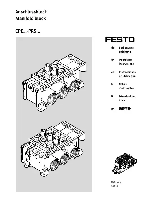
deBedienungs-anleitung enOperating instructions esInstrucciones de utilización frNoticed’utilisation itIstruzioni per l’uso zh操作手册80030841204eAnschlussblock Manifold blockCPE…-PRS…CPE...-PRS...Festo CPE...-PRS...-Z61204e2Es bedeuten/Symbols/Símbolos/Symboles/Simboli/表示:Einbau und Inbetriebnahme darf nur durch Fachpersonal mit entsprechender Qualifika-tion gemäßdieser Bedienungsanleitung durchgeführtwerden.Warnung Warning Advertencia Avertissement Avvertenza 警告Hinweis Note Nota Nota Nota注意UmweltEnvironment Reciclaje Recyclage Ambiente环境Zubehör Accessories Accesorios Accessoires Accessori附件Installation and commissioning may only be performed in accordance with these instruc-tions by technicians with appropriate quali-fications.El montaje y la puesta a punto sólo deben ser realizados por personal especializado debidamente cualificado y según estas ins-trucciones de utilización.Le montage et la mise en service doivent exclusivement être réalisés par un personnel spécialisédisposant des qualificationsadéquates,conformément àla notice d’utili-sation.Le operazioni di montaggio e messa in servi-zio devono essere eseguite solo da perso-nale specializzato provvisto di apposita qualifica,in conformitàalle istruzioni per l’uso.安装与调试必须由具备相应资质的专业人员按照操作手册来实施。
华为E589 4G移动WiFi用户指南说明书

Thank you for choosing Huwei E589 4G Mobile WiFiThis guide briefly describes the functions of your Huawei E589 4G Mobile WiFi. For more details, see help on the web management page. See” Accessing the Web Management Page” on page 13.Copyright © Huawei Technologies Co., Ltd. 2012. All rights reserved.THIS DOCUMENT IS FOR INFORMATION PURPOSE ONLY, AND DOES NOT CONSTITUTE ANY KIND OF WARRANTIES.Getting to Know Huawei E589 4G Mobile WiFi Connection ScenarioAny WiFi device can be connected to the Internet through your Huawei E589 4G Mobile WiFi. You can connect up to 10 different devices. The actual connection procedure depends on the operating system of the WiFi device. The connection scenario illustrated here is for your reference.Getting to know your Huawei E589 4G Mobile WiFi No. Item1 Screen2 WPS button●Press it twice consecutively to displaythe SSID and wireless network key.●Press and hold it until a WPSactivation animation is displayed toenable the WPS function.3 Power/Wi-Fi button4 SIM card slot5 Strap hole6 USB port7 Reset button8microSD card slotScreenNo. Item1 Signal strength2 Network3 ● Wi-Fi enabled ● Number of devices connected4 Internet connection status5 ● New messages ● Number of new messages6 Battery level7 International roaming state 8 ● Traffic data ● Connection duration 9● A: Auto mode ● M: Manual mode4GNote:●WiFi: Wireless Fidelity●WPS: WiFi Protected Setup●Traffic statistics are for your reference only. To obtain the actual traffic data, contactyour service provider.SSID and Wireless Network KeyTo connect a WiFi device to your Mobile WiFi, an SSID and a wireless network key aretwice consecutively to display the current SSID and wireless network key on the screen.Before You StartInserting the SIM CardCaution:Do not use any SIM card that is not standard oris incompatible with the Mobile WiFi. Otherwise, theMobile WiFi may be damaged.Insert the SIM card in the card slot. Be sure that the SIM card is facing in the right direction, as shown in the following picture , and then slide the SIM card into the slot.Inserting the micro SD CardInsert the micro SD card into the Mobile WiFi, as shown in the picture below.●The microSD card is an optional accessory. You may purchase one yourself to enhancedata memory.●To remove the microSD or SIM card, press in the card gently. The microSD or SIM cardwill pop out for removal.●Do not remove the microSD or SIM card when the card is in use. Otherwise, the cardas well as your Mobile WiFi may get damaged and the data stored on the card may be corrupted.Charging the BatteryCharge your Mobile WiFi the first time you use it or if it has not been used for a long time. Method 1: Using the charge rCaution:Only use the charger provided with yourMobile WiFi device. Use of anincompatible charger or one from anunknown manufacturer may cause theMobile WiFi to malfunction, fail, or couldeven cause a fire. Such use voids allwarranties, whether expressed or implied, on the product.Method 2: Connecting to a PC for chargingConnect the Mobile WiFi to a PC using a compatible data cable.Accessing the Internet via Wi-Fi ConnectionBy default, management parameters are preset on the Mobile WiFi according to the requirements of the service provider. Follow the steps below to quickly access the Internet. For details on how to set management parameters, see help on the web management page.Step1: Power on the Mobile WiFiuntil the screen lights up.Note: to power off theMobile WiFi.Step2: Establish a WiFi ConnectionMake sure that the WiFi is enabled1. Select Start > Control Panel > Network Connections > Wireless Network Connection.Note: To set up a WiFi connection, the PC must have a wireless network adapterinstalled. If Wireless Network Connection is displayed, a wireless network adapter is available. Otherwise, check to make sure a wireless network adapter is installed.2. Click “View available wireless networks“ to display a list of WiFi’s available.3. Select a network indicated by the SSID of the Mobile WiFi, and then click “Connect”.Note:●If the encryption parameter is already set for the Mobile WiFi, the Wireless Network●twice consecutively to display the current SSID and wireless network key on4. Wait until the wireless connection icon is displayed in the status area in the lowerright corner of the PC screen.Step3: Access the InternetAfter you establish a WiFi connection successfully, you can access the Internet using the following modes.Caution: Please select a proper Internet connection mode based on your service expense. For example, if you are subscribed to the time-based network service, you are recommended to select Manual mode. For details about the service expense, consult your service provider.Mode OperationsAuto After the Mobile WiFi is powered on, it will connect to the Internet automatically. If there is no data transmission over a period of time, the Mobile WiFi automatically terminates the Internet connection.Manual Launch the web management page and follow the prompts to connect to or disconnect from the network.Note:●Launch the web management page to select the mode for accessing the Internet.●You can choose whether to enable the Mobile WiFi to connect to the Internetautomatically even while you are roaming. If this function is disabled, the Mobile WiFi automatically disconnects from the Internet while you are roaming. To access theInternet, set up a connection manually.Accessing the Web Management Page1. Make sure that the connection between the Mobile WiFi and the client is proper.2. Start the Internet browser and enter http://192.168.1.1 in the address bar.3. Enter the password and log in to the web management page.Note:The default password is admin.Daily UsePower Saving ModeIf no operation is performed on the Mobile WiFi within a preset period, the screen turns off. Press any key to light up the screen.If the Mobile WiFi is powered by the battery only, choose whether to enable the Mobile WiFi to turn off WiFi automatically. If this function is enabled and no WiFi devices access the Mobile WiFi for a preset period, the Mobile WiFi turns off WiFi automatically. You can press any key to turn WiFi on again.Validating the PIN CodeIf PIN code protection is enabled, log in to the web management page and follow the prompts to enter the correct PIN code. Both PIN and PUK are delivered with the SIM card. For details, consult your service provider.Establishing a WPS ConnectionIf a WiFi client connected to the Mobile WiFi supports the WPS function, a wireless network key will be automatically generated without manual input. To establish a WPS connection, perform the following steps:1. Power on the Mobile WiFi.2. Start the client.3.Note:the screen to enable the WPS function of theMobile WiFi.4. Enable the WPS function of the client.Note: For WPS operations on the client, see the user guide of the client.Restoring Factory DefaultsIf you forget the changes you have made to someparameters, you may restore factory defaults andreconfigure the Mobile WiFi. To restore thefactory defaults,press and hold the RESET buttonuntil the screen turns off. All factory defaultsettings are successfully restored.Note: Restoring factory defaults deletes all personal configuration settings and restores all web-based management settings and parameters to their default values.Example 1: Wi-Fi Connection to Game Machine (Sony PSP)1. Turn on the PSP WLAN switch.2. Select “Settings > Network Settings”.3. Select “Infrastructure Mode” to connectto your local Wi-Fi access point.4. Select “New Connection” to specify aneasy to remember connection name.5. Select “Scan” to detect all networkswithin range. The access point list isdisplayed.6. Select a network indicated by the SSID ofthe Mobile WiFi. First press the“►“ button of your game machine toconfirm the SSID and then press it againto input the wireless network key.Note: twice consecutively to display the current SSID and wireless network key on the screen.7. Press the “►“ button of your gamemachine to continue, and then press the“X” button to save the settings.8. Select “Test Connection“ to check theconnection.9. Go to “Internet Browser”.Example 2: WiFi Connection to a Smart Phone (iPhone) 1. Select “Settings > WiFi”, and then turn onWiFi.2. Automatically detect the networks in rangeand display the access point list.3. Select a network indicated by the SSID of theMobile WiFi.4. If necessary, enter a password and tap “Join”.(Networks requiring a password appear witha lock icon.)Note: Some WiFi clients such as iTouch, PS3 andNDSi can also access the Internet via the MobileWiFi. For details, see the user guides of the WiFiclients.TipsIf the Mobile WiFi is placed in an environment with poor ventilation, it may overheat after extended use. When the Mobile WiFi overheats, it will switch off and disconnect from the network automatically to protect itself. If this happens, place the Mobile WiFi in awell-ventilated location, then restart the Mobile WiFi.If you are experiencing difficulties using the Mobile WiFi, try the following:●See help on the web management page.●Restart the Mobile WiFi.●Restore the factory defaults.●Contact your service provider.Version: V100R001_01 Part Number: 31010***。
Huawei B593 B593u-12 4G LTE CPE Quick Setup
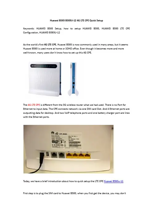
Huawei B593 B593U-12 4G LTE CPE Quick SetupKeywords: HUAWEI B593 Setup, how to setup HUAWEI B593, HUAWEI B593 LTE CPE Configuration, HUAWEI B593U-12As the world's first 4G LTE CPE, Huawei B593 is now commonly used in many areas, but it seems Huawei B593 is used more at home or SOHO office. Even though it becomes more and more well-known, many users don't know how to set up this 4G CPE.The 4G LTE CPE is different from the 3G wireless router what we had used. There is no Port for Ethernet to input data. The CPE connects network via one SIM card Slot. And 4 Ethernet ports are outputting data for desktop. And two VoIP telephone ports and one battery charger port are lines with the Ethernet ports.Today, we have a brief introduction about how to quick setup the LTE CPE Huawei B593u-12.First step is to plug the SIM card to Huawei B593; when you first get the device, you may don'tknow where to plug the SIM card, below the image will show the slot for SIM card.Then plug the power adapter and press the power button to start the device. After power on, the indicators on the front of Huawei B593 will start shinning. After few second, you could find the SSID in your PC, and then connect it through the WLAN Key on the back stick of the CPE.After connected with the WiFi, land the home page http://192.168.1.1 and default password is adminThen click the Setup and the management page will guide to Setup WizardIf the SIM card PIN is disabled, click next to Internet setting, users could choose the network mode and connection mode per users’ preference.Then click next to set up WLAN, users could setup the WiFi mode, Country mode, Channel, SSID name and to hide the broadcast.Then next step ot set up the WLAN Security, users could setup the Security mode, WiFi key and WPA Encryption mode.Then click to next and submit the setting and. After few seconds, the setup is finished and users could surf internet.Sometimes, users may want to have better signal and high data transmission, so it’s necessary to use 4G LTE External antenna for HUAWEI B593. But there is no setting in HUAWEI B593 4G LTE CPE. It could enhance the signal invisibly.。
Vodafone 4G CPE 产品参考手册说明书
Vodafone Group response on draft BEREC guidelines on the criteria for a consistent application of Article 61(3) EECC31 July 2020We appreciate the opportunity to comment on this consultation and trust that our comments are helpful to BEREC and National Regulatory Authorities (NRAs) as well as to other stakeholders. We remain at your disposal to discuss our submission to the consultation, or any other aspect relevant in the context of the latter.To inquire about our response please contact:Ana BaideSenior Manager Policy & Public AffairsMarkets & Deployment LeadGroup External Affairs+44 7500 883876We are supportive of BEREC’s work in the development of guidelines on the criteria for a consistent application of Article 61(3) of the European Electronic Communications Code (EECC).We agree with the detailed points raised in the GIGA Europe submission regarding the key concerns with the proposed BEREC guidelines. In addition to those concerns, we would like to provide the additional comments as set out below.Preserving incentives to invest in critical infrastructureDigital connectivity and networks are critical infrastructure providing essential services for the functioning of European economies and societies. The COVID19 crisis has brought the importance of investments in modernising digital networks into sharp focus. The ability to invest, enhance capacity and expand the reach of connectivity services ought to be the key objectives of ensuring greater societal resilience and economic recovery from the turmoil of the current pandemic.The EECC is a key instrument through which the EU is set to incentivise appropriate investments in order to achieve these policy goals. It is therefore of paramount importance that all relevant aspects of the framework act in harmony towards achieving its purpose. Symmetrical obligations, such as the ones set out in Article 61(3), can be intrusive and undermine incentives to invest. This is recognised in Recital 152 of the EECC:However, as such obligations can in certain cases be intrusive, can undermine incentives for investments, and can have the effect of strengthening the position ofdominant players, they should be imposed only where justified and proportionate to achieving sustainable competition in the relevant marketsWe do not believe that the proposed guidelines are currently providing clearly defined boundaries to ensure that the article will only be applied where “justified and proportionate to achieving sustainable competition in relevant markets”. The guidelines need to establish clearly defined boundaries for access regulation under the significant market power (SMP) regime and Article 61(3) to ensure any negative effects on investments, competition and consumer welfare will be avoided.Without clear boundaries, there also is apparent risk that NRAs may inadvertently establish new access regulation by circumventing the burden of a proper SMP analysis, in particular regarding potential regional or local submarkets, without the need for necessary proof and rigor of market analysis. This is even more crucial as the criteria for application of measures according to Article 61(3) are largely similar to the well-established three criteria test from SMP analysis. Such distorted outcomes would have adverse effects of investment, competition and consumer welfare and would undermine the overall purpose and goals of the EECC.The purpose of Article 61(3) and its place within the regulatory frameworkArticle 61(3) allows for access regulation outside the well-established SMP framework by introducing symmetric regulation that can be applied to any operator. It is based on the concept of economic network replicability and is intended to provide an additional tool for access regulation.Access to electronic communication networks and physical infrastructure suitable for the rollout of these networks can be granted under three different relevant regimes. In situations where there is (i) no competition for the market (state aid), no effective competition (SMP), and infrastructure bottlenecks requiring measures to unlock supply (BCRD). Not least given the similarity of the latter with the situation that Article 61(3) is supposed to deal with, any access under this article must, in order to be effective and proportionate, take into account other access obligations set under the more encompassing and therefore higher ranking regulatory access regimes.At the time when Article 61(3) was introduced into the EECC, there was some doubt as to whether the SMP regime would effectively deal with situations where anti-competitive oligopolies could create access bottlenecks. The developments in the Netherlands and Belgium show that joint SMP can be assessed by NRAs under the EECC. Therefore, the original purpose, relevance and applicability of Article 61(3) is no longer sufficiently clear. We therefore consider that the BEREC guidelines must be explicit and clear on certain fundamental aspects of the overall regime, and the place that Article 61(3) may find among them.The guidelines should primarily safeguard the pro-competitive outcomes of a well-established regime. The boundaries between a competition analysis under the SMP framework and under symmetrical regulation must be abundantly clear and robust. Specifically, conditions that should be met in order for Article 61(3) to be used to impose access beyond in-house wiring should be all of the following:1.Any other access obligations would be insufficient. This should include SMP, BCRD andstated aid rules, as well as in-building access to be applied and considered in the first instance.2.In an existing or emerging market situation. The guidelines currently do not providesufficiently clear guidance on the assessment that needs to be made on whether there is an underlying market situation (either in existence, or emerging) that significantly limits competitive outcomes for end-users. As noted by GIGA Europe, this assessment should be made prior to assessing whether or not high and non-transitory barriers to replication exist. In order for Article 61(3) to apply, such a clear assessment would then need to be satisfied.3.The market situation would limit competitive outcomes to end-users. The SMP frameworkis underpinned by the principle of end-user outcomes consistent with a competitive market and the same threshold should be applied when using Article 61(3), however only where the points 1, 2 and 4 set out here are also satisfied.4.High and non-transitory economic or physical barriers to replication exist. The guidelinesare not sufficiently clear on defining the barriers to replication in this context. In terms of the logic of hierarchy of the framework, the replication barriers could be said to be transitory where SMP regulation suffices to let challengers replicate network assets. Additional commentsAs noted above, we support the detailed points raised in the GIGA Europe submission, and would like to note that the following issues it raises need to be reflected in the guidelines:∙Proportionality. The guidelines should recognise the significant burden placed on network operators by possible obligations by introducing greater proportionality by placing some onus on access seekers to demonstrate that their request is reasonable, appropriate and necessary.∙Active/virtual access.The guidelines need to provide more guidance on the circumstances that warrant active/virtual access. We consider that any circumstances warranting active/virtual access must be a last resort and this should be clearly set out. It should be made clear that passive access is the remedy of first choice. Only where passive access cannot be realized due to technical impossibility, active/virtual access may be taken into account. However, even in such circumstances the imposed access points may not merely replicate usual bitstream access points on local, regional or even higher network level but must be located strictly at the “first concentration point beyond xx”.This is necessary notwithstanding the proposed cost/revenue consideration of access seekers and the “efficient operator” concept within the draft guidelines (see our comments on this issue below).∙The introduction of the concept of “clusters”. The concept of analysing access requests based on “clusters” is not included in the wording of Article 61(3). We are hesitant to expand the scope and wording of this provision as this may introduce further confusion as to its application. If this concept is to remain in the guidelines, we would encourage BEREC to provide greater clarity on its application – we refer to the GIGA Europe comments for some detailed suggestions.∙Definition of “efficient operator” and proposed cost/revenue analy sis for determination of feasible access point:The inclusion of the “efficient operator”concept in order to determine a feasible access point is both cumbersome and dubious, as well as taking ona potentially inconsistent meaning with its use in other aspects of the regulatoryframework. It considers solely the optimal requirements from the point of an access seeker or wholesale operator and does not appropriately recognise the cost and burden of an access provider. The outcome of the proposed cost/revenue analysis for an access seeker and the assignment of an “efficient operator” is mostly contingent on the network presence or footprint assumed in the analysis. A feasible access point according to cost/revenue profitability is obviously different for incumbent infrastructure with both national and local presence than for a local or regional competitor with a limited footprint.In the proposed formulation of this term, the determination of what constitutes an “efficient operator” includes arbitrary assumptions. This concept should therefore be removed from the guidelines. A more adequate approach is to take supply side issues into account instead.∙Operators of varying sizes.The guidelines need further clarity on how requests from operators of varying sizes should be dealt with.∙Consistency of terms used with the overall framework.Ensure the terms used in the guidelines have a meaning consistent with the rest of the regulatory framework. we specifically note inconsistent use of the term “efficient operator” which is likely to introduce confusion and complexity.We refer to the GIGA Europe submission for the detailed discussion of these points.。
华为B315s-22 LTE CPE V200R001产品描述说明书
HUAWEI B315s-22 LTE CPE V200R001Product Description Issue 01Date 2014-12-15Copyright © Huawei Technologies Co., Ltd. 2014. All rights reserved.No part of this document may be reproduced or transmitted in any form or by any means without prior written consent of Huawei Technologies Co., Ltd.Trademarks and Permissionsand other Huawei trademarks are trademarks of Huawei Technologies Co., Ltd.All other trademarks and trade names mentioned in this document are the property of their respective holders.NoticeThe purchased products, services and features are stipulated by the contract made between Huawei and the customer. All or part of the products, services and features described in this document may not be within the purchase scope or the usage scope. Unless otherwise specified in the contract, all statements, information, and recommendations in this document are provided "AS IS" without warranties, guarantees or representations of any kind, either express or implied.The information in this document is subject to change without notice. Every effort has been made in the preparation of this document to ensure accuracy of the contents, but all statements, information, and recommendations in this document do not constitute a warranty of any kind, express or implied. Huawei Technologies Co., Ltd.Address: Huawei Industrial BaseBantian, LonggangShenzhen 518129People's Republic of ChinaWebsite: /en/Email: *****************About This Document SummaryThis document provides information for product features, main functions and services,technical specifications and technical references.This document includes:Chapter Details1 Product Overview Describes the appearance and main services of product2 Features Describes the product features3 Technical Specifications Describes the specifications of product hardware,software and user interface4 Services and Applications Describes the main functions and applications5 System Structure Describes the product system structure6 Packing List Describes the devices and accessories of the productThe document is an invitation to offer but not an offer. It is intended to describe the general features andfunctions of products. The features and functions of certain products vary with requirements ofcustomers.HistoryIssue Date Details01 2014-12-15 Initial official release.ContentsAbout This Document (ii)1 Product Overview (1)2 Features (3)3 Technical Specifications (4)3.1 Hardware Specifications (4)3.2 Antenna and Radio Frequency Specifications (6)3.3 Software Specifications (8)4 Services and Applications (11)4.1 Data Services (11)4.1.1 Accessing the Internet Through a Mobile Network (LTE/UMTS/GSM) (11)4.1.2 Accessing the Internet Through an Ethernet Network (12)4.2 V oice Services (12)4.3 SMS (13)4.4 Security Service (13)4.5 USB Sharing services (13)4.6 Local management and maintenance (13)5 System Structure (14)5.1 System Architecture Diagram (14)5.2 Functional Modules (14)6 Packing List (15)A Acronyms and Abbreviations (16)1 Product Overview The HUAWEI B315s-22 LTE CPE (B315s-22 for short) is a wireless gateway that integrates LTE and high-speed Ethernet uplink access, which provides users with flexible and diversified data access and voice services.The frequency bands of the product are as follows.●LTE: Band 1/3/7/8/20/38FDD 2100 MHz/1800 MHz/2600 MHz/900 MHz/800 MHz/TDD 2600 MHz●UMTS: Band 1/8 2100 MHz/900 MHz●GSM: Band 2/3/5/8 1900 MHz/1800 MHz/850 MHz/900 MHzThe B315s-22 supports the following standards:●Long Term Evolution (LTE)●Dual Carrier High Speed Packet Access Plus (DC-HSPA+)●High Speed Packet Access Plus (HSPA+)●High Speed Packet Access (HSPA)●Wideband Code Division Multiple Access (WCDMA)●Enhanced Data Rates for Global Evolution (EDGE)●General Packet Radio Service (System) (GPRS)●Global System for Mobile Communications (GSM)●Gigabit Ethernet (GE)The B315s-22 supports wired and wireless network access, and provides data routing service. The B315s-22 provides the following services:●Data service●Voice service●SMS●Security service●Local maintenance management functionFigure 1-1B315s-22 appearance2 FeaturesThe B315s-22 mainly supports the following features:●Access to LTE/DC-HSPA+/HSPA+/HSPA/WCDMA/EDGE/GPRS/GSM wirelessnetworks●Access to Gigabit Ethernet networks●High-speed data access−LTE FDD: DL 150 Mbps, UL 50 Mbps−LTE TDD: DL 112 Mbps, UL 10 Mbps−DC-HSPA+: DL 42 Mbps, UL 5.76 Mbps−HSPA+: DL 21 Mbps (64QAM) / 28 Mbps (MIMO), UL 5.76 Mbps−HSPA: DL 14.4 Mbps, UL 5.76 Mbps−WCDMA PS: 384 kbps−EDGE: DL 296 kbps, UL 236.8 kbps−GPRS: 85.6 kbps●Support maximum data transmission rate of 300 Mbps 802.11b/g/n●Compatibility with RJ11 telephone ports; can be set to V oice over Internet Protocol(V oIP) or Circuit Switch (CS) voice mode●USB 2.0 host port●External antenna port●Support for HUAWEI Mobile WiFi App●WPS 2.0●HOTA updates●Built-in DHCP Server, DNS RELAY and NAT●Security services. Provides instant protection to block potential security risks andintrusion attempts●Windows 8.1, Windows 8, Windows 7, Windows Vista SP1/SP2, Windows XP SP3, andMac OS X 10.9, 10.8, and 10.7 with latest upgrades●User-friendly design of LED indicator. Easy to observe the status of equipment.3 Technical Specifications 3.1 Hardware SpecificationsTable 3-1Technical specifications of the B315s-22 main unitItem DescriptionTechnical standard WAN ●Mobile Network:LTE/DC-HSPA+/HSPA+/HSPA/WCDMA/EDGE/GPRS/GSM●Gigabit Ethernet: IEEE 802.3/802.3uLAN IEEE 802.3/802.3uWLAN IEEE 802.11b/g/nWorking frequency band LTE Band 1/3/7/8/20/38FDD 2100 MHz/1800 MHz/2600 MHz/900 MHz/800MHz/TDD 2600 MHzUMTS Band 1/8 2100 MHz/900 MHzGSM Band 2/3/5/8 1900 MHz/1800 MHz/850 MHz/900 MHz WLAN 2.400 GHz - 2.474 GHzExternal port ●One power adapter port●Three LAN ports (RJ45)●One WAN/LAN port (RJ45)●One USB 2.0 host port●One phone port (RJ11)●Two external antenna ports●One SIM card slotItem DescriptionIndicator ●One power indicator●One Internet status indicator●One Wi-Fi/WPS indicator●One LAN indicator●One group of signal strength indicators Button ●One Power ON or OFF switch●One WPS button●One Reset buttonMaximum transmit power LTE Conform to 3GPP Power Class 3 DefinitionUMTS 23 dBm (+2 dB/-2 dB)GSM ●850 MHz/900 MHz: 33 dBm (+2 dB/-2 dB)●1800MHz/1900MHz: 30 dBm (+2 dB/-2 dB) WLAN 802.11b 16 dBm(+3 dB/-3 dB)@11 Mbps 802.11g ●17 dBm(+3 dB/-3 dB)@6 Mbps●17 dBm(+3 dB/-3 dB)@54 Mbps802.11n ●17 dBm(+3 dB/-3 dB)@MCS0●17 dBm(+3 dB/-3 dB)@MCS7Receiving sensitivity LTE Conform to 3GPP DefinitionUMTS ●2100MHz:*****************●900MHz:***************** GSM -104 dBmWLAN 802.11b ≤ -92 dBm@1 Mbps≤ -85 dBm@11 Mbps 802.11g ≤ -88 dBm@6 Mbps≤ -70 dBm@54 Mbps 802.11n HT20 ≤ -88 dBm@MCS0≤ -68 dBm@MCS7802.11n HT40 ≤ -84 dBm@MCS0≤ -66 dBm@MCS7Power consumption< 12 WAC/DC power supply ●AC: 100 V - 240 V ●DC: 12 V/1 ADimensions(Maximum)186 mm (Width) x 139 mm (High) x 46 mm (Deep)Item DescriptionWeight About 275 g (excluding the power adapter)Temperature ●Working temperature: 0°C to 40°C●Storage temperature: -20°C to +70°CHumidity 5% - 95%3.2 Antenna and Radio Frequency SpecificationsTable 3-2L TE/UMTS/GSM main diversity antenna specificationsItem DescriptionFrequency ●703 MHz - 960 MHz●1710 MHz - 2690 MHzInput50 ΩimpedanceStanding wave< 3ratioEfficiency ≥ -4.5 dB@703MHz - 960MHz≥ -3.5 dB@1710MHz - 2690MHzH side gain ≥ 1 dBi (horizontal level)Polarization Linear polarizationTable 3-3L TE/UMTS sub diversity antenna specificationsItem DescriptionFrequency ●703 MHz - 960 MHz●1710 MHz - 2690 MHzInput50 ΩimpedanceStanding wave< 3ratioEfficiency ≥ -4.5 dB@703MHz - 960MHz≥ -3.5 dB@1710MHz - 2690MHzH side gain ≥ 1 dBi (horizontal level)Polarization Linear polarizationTable 3-4WLAN 2.4 GHz antenna specificationsItem DescriptionFrequency 2.400 GHz - 2.474 GHzInput50 ΩimpedanceStanding wave< 2ratioEfficiency ≥ -3 dBH side gain ≥ 1 dBi (horizontal level)Polarization Linear polarizationTable 3-5External antenna specifications●The external antenna is an optional accessory. Signals may be weak in some areas; thus, you canchoose whether to use the external antenna.●The external antenna can be used indoor only. Put it near the window when using to get better signal.●Avoid thunderstorms when using.Item DescriptionTechnicalLTE/DC-HSPA+/HSPA+/HSPA/WCDMA/EDGE/GPRS/GSM standardFrequency ●703 MHz - 960 MHz●1710 MHz - 2690 MHzInput50 ΩimpedanceStanding wave< 3ratioH side gain ≥ 3 dBi (horizontal level)Polarization Linear polarizationInterfaceSMA-J1.5standard3.3 Software SpecificationsTable 3-6Software specificationsItem DescriptionMobile network APN managementGigabit Ethernet ●WAN/LAN auto-negotiation●PPPoE username and passwordData service LTE FDD DL 150 Mbps, UL 50 MbpsLTE TDD ●Configuration 1: DL 80 Mbps, UL 20 Mbps●Configuration 2: DL 112 Mbps, UL 10 MbpsDC-HSPA+ DL 42 Mbps, UL 5.76 MbpsHSPA+ DL 21 Mbps (64QAM) / 28 Mbps (MIMO)UL 5.76 MbpsHSPA DL 14.4 Mbps, 10.2 Mbps, 7.2 Mbps, 3.6 MbpsUL 5.76 Mbps, 2 MbpsWCDMA PS DL 384 kbps, UL 384 kbpsEDGE DL 296 kbps, UL 236.8 kbps (depending on thenetwork configuration)GPRS DL 85.6 kbps, UL 85.6 kbps (depending on thenetwork configuration)WLAN ●802.11b: 11 Mbps, 5.5 Mbps, 2 Mbps, 1 Mbps●802.11g: 54 Mbps, 48 Mbps, 36 Mbps, 24 Mbps,18 Mbps, 12 Mbps, 9 Mbps, 6 Mbps●802.11n: 300 Mbps (HT40 MCS15), 144.4 Mbps(HT20 MCS15)Web management Web management pageAccess to the web management page through an IPv4 addressWeb browser ●IE 8.0 (Windows XP)●IE 8.0 and above (Windows 7/Vista)●IE 10.0 and above (Windows 8)●Firefox 24.0 and above●Safari 6.0 and above (MAC)●Opera 12.0 and above●Chrome 27.0 and aboveItem DescriptionGateway Router Default routing (the routing address is 0.0.0.0). Youcan set the WAN connection to the default routing togenerate default routing table itemsDHCP Server ●The default gateway address is 192.168.8.1●The default IP addresses of the DHCP server isfrom 192.168.8.100 to 192.168.8.254. The IPaddresses can be customized.●The default DHCP lease is 24 hours●The DHCP Server can be enabled or disabled ●The address pool of the DHCP server can beconfigured●The lease can be configuredNAT ●NAT, NAPT (compliant with RFC2663, RFC3022and RFC3027)●CONE NAT●Fragment message identification for normal NAT●ALGARPICMPDNS RelayIPv6/IPv4 dual stackSMS Writing, sending, and receiving messagesVoice service (Alternatively) VoIP voice ●SIP voice services●G.722/G.711a/G.711u/G.729/G.726 encoding anddecodingCS voice ●CS voice services over UMTS/GSM networks●CSFBFirewall setup Firewall switchURL filterVirtual serverPort forwardingPort triggeringDMZ serviceALG settingsRemote managementLAN 10 Mbps, 100 Mbps, and 1000 Mbps auto-negotiationItem DescriptionMDI/MDIX auto-sensingIEEE 802.3/802.3u is compatibleWLAN IEEE 802.11b/g/n4 SSID broadcast and hiding are supported in maximum.WPS 2.0WMMEncryption ●WEP●AES●TKIP+AESSecurity mode ●WPA2.0 PSK●WPA1.0/WPA2.0 PSK●WEP Shared Key (four keys at most)●OpenMAC address authentication ●White list●Black list●The preceding two lists cannot coexist ●Up to 10 MAC address itemsSTA management ●Supports inquiry of STA status●Supports limit of access users (Access fromup to 32 users)HUAWEI Mobile WiFi App View service provider's name, the roaming status and signal strength. View the data traffic usage and SMS.Manage the connected devices.Change SSID and password.System requirement Windows 8.1, Windows 8, Windows 7, Windows Vista SP1/SP2, Windows XP SP3, and Mac OS X 10.9, 10.8, and 10.7 with latest upgradesYour computer's hardware system should meet or exceed the recommended system requirements for the installed version of OS4 Services and Applications 4.1 Data ServicesThe B315s-22 can access the Internet through mobile networks, and Ethernet networks. Byconnecting to the B315s-22 using Wi-Fi or a network cable, users can get access tohigh-speed Internet services and establish a local area network (LAN).4.1.1 Accessing the Internet Through a Mobile Network(LTE/UMTS/GSM)The B315s-22 can access the Internet through mobile networks.Figure 4-1Accessing the Internet through a mobile network4.1.2 Accessing the Internet Through an Ethernet NetworkConnect the B315s-22's WAN/LAN port to a wall-mounted Ethernet port using a networkcable.Figure 4-2Accessing the Internet through an Ethernet network4.2 Voice ServicesThe B315s-22 provides one telephone port that can be connected to telephones for calling.Figure 4-3Connecting telephones to the B315s-224.3 SMSThe B315s-22 supports message writing/sending/receiving and group sending (up to 50contacts at a time). You can manage messages through the Web page, such as inbox, outbox,draft.4.4 Security ServiceThe B315s-22 supports various security features, such as the firewall, user authentication, andPIN protection, protect users against security threats from the Internet when users are usingnetwork services.4.5 USB Sharing servicesWith one USB port, users can connect a USB storage device to the USB port on the B315s-22to save and share files. Users can also connect a USB printer to the USB port on the B315s-22for printing services.Figure 4-4Connecting USB devices to the B315s-224.6 Local management and maintenanceThe B315s-22 supports local configuration through the Web page. You can accomplish devicemanagement, network configuration and ensure normal and stable performance.5 System Structure 5.1 System Architecture DiagramFigure 5-1System architecture5.2 Functional Modules●Mobile network access: The B315s-22 adopts the LTE/UMTS/GSM access technology atthe WAN side, can access the wireless broadband packet-based.●WLAN AP function: 802.11b/g/n compliant WLAN AP interface is provided, used forwireless networking at home. The interface is compliant with the IEEE 802.11b/g/nstandard and the WPA-PSK/WPA2-PSK/WEP security authentication.●DHCP/DNS: The DHCP server dynamically allocates IP addresses to PCs. The DNSparses domain names.●Web management: You can configure, modify and query the configuration information ofthe B315s-22.●Routing and NA T: High-speed routing capability. With the built-in NA T, the B315s-22,together with wireless broadband packet-based network devices, can provide flexiblebroadband access solutions and networking schemes.6 Packing List Table 6–1 shows the devices and accessories of the B315s-22.Table 6-1Packing listDescription Quantity RemarksWireless Gateway 1 StandardPower supply adapter 1 StandardQuick Start 1 StandardEthernet cable 1 StandardWarranty card 1 OptionalPhone cable 1 OptionalHUAWEI B315s-22 wireless gateway also provide external antenna as optional for you to choose.HUAWEI B315s-22 LTE CPEProduct Description A Acronyms and AbbreviationsA Acronyms and AbbreviationsAAC Alternating CurrentARP Address Resolution ProtocolAP Access PointAPN Access Point NameCCPE Customer Premises EquipmentCS Circuit SwitchCSFB Circuit Switched FallbackDDHCP Dynamic Host Configuration ProtocolDL DownlinkDNS Domain Name ServerGGE Gigabit EthernetHHSPA High Speed Packet AccessHSPA+ High Speed Packet Access PlusHSDPA High Speed Downlink Packet AccessHSUPA High Speed Uplink Packet AccessHT High ThroughputIIP Internet ProtocolHUAWEI B315s-22 LTE CPEProduct Description A Acronyms and AbbreviationsIssue 01 (2014-12-15) Huawei Proprietary and ConfidentialCopyright © Huawei Technologies Co., Ltd. 17ICMP Internet Control Message ProtocolLLAN Local Area NetworkLED Light Emitting DiodeLTE Long Term EvolutionMMCS Modulation and Coding SchemeNNAT Network Address TranslationPPOTS Plain Old Telephone ServiceTTKIP Temporal Key Integrity ProtocolUUMTS Universal Mobile Telecommunications System UL UplinkVVoIP Voice over Internet ProtocolWWAN Wide Area NetworkWLAN Wireless Local Area NetworkWCDMA Wideband Code Division Multiple AccessWi-Fi Wireless Fidelity。
【深圳】LTE CPE B593操作指导书
B593操作指导书拟制日期2011-10-25 审核日期批准日期华为技术有限公司版权所有侵权必究(仅供内部使用)修订记录目录1了解CPE (4)1.1外观 (4)1.2指示灯 (4)2连接设备 (6)3版本 (6)3.1版本信息确认 (6)4入网配置 (9)4.1维护工具介绍 (9)4.2整机入网 (10)4.2.1软USIM/硬SIM设置(无硬件SIM卡) (10)4.2.2设置安全功能开关(根据网络侧配置) ............................ 错误!未定义书签。
4.2.3支持频段设置................................................................... 错误!未定义书签。
4.2.4设置候选频点(该项不是入网必须配置)................... 错误!未定义书签。
4.2.5UE能力修改 ..................................................................... 错误!未定义书签。
4.2.6正常入网 (20)4.2.7入网异常 (21)4.3WIFI测试参数配置 (25)5FAQ (26)5.1CPE上电,发现MODE灯为紫红色快闪。
(26)5.2信令接入正常,MODE灯显示为蓝色快闪,但是无法进行下载业务。
(26)5.3CPE软硬件版本号查看方法: (27)5.4CPE登录密码修改: (28)5.5CPE自动分配PC的IP不是192.168.1.2? (28)5.6WIFI速率偏低 (28)1 了解CPE1.1 外观1 POWER指示灯2 WLAN指示灯3 WPS指示灯4 TEL指示灯5 MODE指示灯6 SIGNAL指示灯7 SIM Card插槽8 POWER按钮9 USB接口10 POWER接口11 USB接口12 TEL接口13 LAN接口14 LAN指示灯15 WPS按钮16 RESET按钮17 WLAN按钮1.2 指示灯CPE在前后面板集成了指示灯,显示设备运行状态。
CPE安装及使用说明书
CPE安装及使用客户端CPE夹具安装步骤示意图1、首先打开产品包装箱,可以看到产品主设备,电源适配器,POE合路器,夹具,螺丝;先把夹具按下图,首先如图把夹具简单的组装好,(圈环、u型夹具钢板、方形小钢块、5号螺丝和垫片各两个)2、按如下把夹夹具两边的活动螺丝卡入设备背部的两条槽孔中,如下图所示:卡入后,调试到适宜的位置拧紧夹具两边的螺丝固定夹具位置即可;3、安装设备时根据所需安装杆的大小调整夹具圈环的大小。
(拧圈环上的一字螺丝)安装成功后如下图所示:下图为产品侧面图:5、电源和POE合路器连接如下图所示:一、使用说明1、系统登录➢请先将本机IP设置为192.168.1.x(2-254)网段:(图1.1:TCP/IP协议设置)➢打开IE浏览器,在地址栏输入http://192.168.1.250/(图1.2:登录界面)➢输入默认用户名:admin,默认密码:admin,点击“登录”,进入WEB 管理初始界面;(图1.3:系统状态)这里可以查看系统的基本信息,运行状态,运行时间,无线配置信息等;在Client模式下,如果设备已经连接上热点AP,则在“无线配置”里面的“状态”显示“Connected”,如果没有连接上,则显示“Scanning”,这里判断设备间是否连接成功的标志。
2、操作模式设备支持两种操作模式: 桥接, 无线ISP, 系统默认是“桥接”模式,普通用户推荐使用桥接模式,设备相当于一个无线终端。
(图2.1:操作模式设置)3、无线设置该菜单项设置无线各项相关参数。
3.1 基本设置该页面设置无线工作在不同模式下相关参数。
(图3.1:无线基本设置)禁用无线网络接口: 勾选将关闭无线功能 .频带: 可选如下模式2.4G Hz(B):11b模式,最高速率是11Mbps2.4G Hz (G):11g模式,最高速率是54 Mbps2.4G Hz(N):11n模式,最高速率是150 Mbps(1T1R)300 Mbps(2T2R)2.4G Hz (B+G):11b/g模式,最高速率分别是11 Mbps和54 Mbps2.4G Hz(G+N):11g/n模式,最高速率分别是54 Mbps和150 Mbps/300 Mbps2.4G Hz(B+G+N):11b/g/n模式,最高速率分别是11 Mbps,54 Mbps,150 Mbps /300 Mbps。
- 1、下载文档前请自行甄别文档内容的完整性,平台不提供额外的编辑、内容补充、找答案等附加服务。
- 2、"仅部分预览"的文档,不可在线预览部分如存在完整性等问题,可反馈申请退款(可完整预览的文档不适用该条件!)。
- 3、如文档侵犯您的权益,请联系客服反馈,我们会尽快为您处理(人工客服工作时间:9:00-18:30)。
学海无 涯
华为单模 CPE-B593s 操作指南
1
学海无 涯
2
学海无 涯
3
学海无 涯
正常情况下: CPE 终端面板上电源指示灯、WIFI 信号指示灯、TD-LTE 信号指示灯均长亮,且显示为蓝
4
学海无涯
灯。 故障判断: 电源指示灯不亮:请检查电源插头是否插好,CPE 终端开关是否开启; WIFI 指示灯不亮:请检查 WIFI 开关是否开启; TD-LTE 信号指示灯不亮:请重新开关 CPE 终端后是否恢复; TD-LTE 信号指示灯显示白灯:为该 CPE 终端仍在搜网中,请耐心等待; TD-LTE 信号指示灯显示红灯:为该 CPE 终端搜索不到网络,请将该 CPE 终端更换摆放位 置试用。 二:CPE 终端 USIM 卡槽和电源开关位置:
二、 登入网速测试界面后,点击“开始”即可进行测速:
8பைடு நூலகம்
学海无 涯
三、 测试完成后,即可得出测试结果: (目前 TD-LTE 速率一般在 10M 左右可视为正常网速,若用户对此不满,请做好用户解释 工作。)
9
三:CPE 终端WIFI 开关和 RESET 键位置(RESET 键:可恢复出厂设置):
5
学海无 涯
四、背面样式: CPE 终端相当于一台路由器,可通过无线搜索终端发出的 WIFI 信号,也可直接通过网线直 连 CPE 终端体验 4G 高速上网。
6
学海无 涯
在机身背面有 CPE 终端WIFI 的 SSID、WIFI 登陆密码。 五、修改密码: 1、网线直连电脑后,输入 password:admin
2、选中WLAN(黄框选中部分),在操作界面中可修改 SSID(红框选中部分)和登入密码 (蓝框选中部分)
7
学海无 涯
六、用户流量查询: 业务受理平台—MOD 免费资源查询 附:网速测试(中国移动导航网站: ) 一、 在中国移动导航网站: 中可以进行网速测试: