1-Wire软件资源指南和驱动程序说明
性能优异的1-Wire网络驱动器
性能优异的1-Wire网络驱动器摘要:本文介绍了一种基于微控制器的1-Wire®主机接口,适用于小规模、中等规模以及大规模的1-Wire网络。
采用精细的阻抗匹配和"智能" (软件控制)强上拉、摆率控制等方法保证网络的可靠工作。
本文给出了软件流程图,有助于用户利用任何适当的微控制器产生正确的复位脉冲、在线检测、写“1”、写“0”以及读时隙的1-Wire时序。
示波器测试曲线说明了驱动器的时间特性以及远距离通信时传输线的影响。
简介1-Wire网络的可靠性在很大程度上取决于主机与1-Wire从机器件之间所采用的通信驱动电路的性能。
本文介绍了一种1-Wire主机端接口,采用精细的阻抗匹配和"智能" (软件控制)强上拉等方法,保证网络在轻载到重载范围内均能可靠工作,且通信距离可达500m。
关于创建可靠的1-Wire网络指南,请参见应用笔记148。
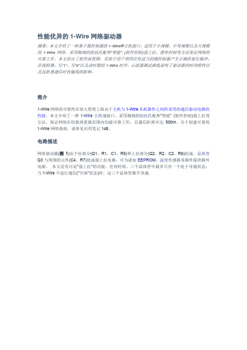
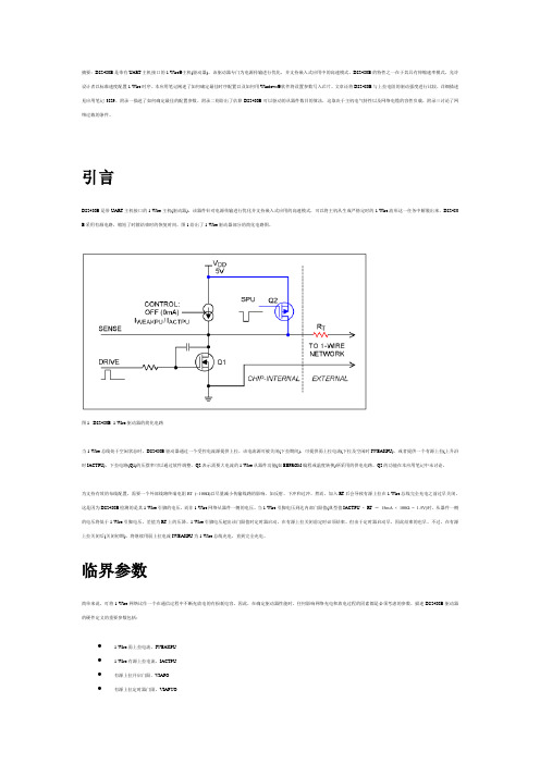
电路描述网络驱动器(图1)由下拉部分(Q1,R1,C1,R5)和上拉部分(Q2,R2,C2,R6)组成。
晶体管Q3与周围的元件(C4、R7)组成强上拉电路,可为诸如EEPROM、温度传感器等器件提供额外电源。
本文没有讨论"强上拉"的功能。
任何时候,三个晶体管中最多只有一个处于导通状态;当1-Wire不进行通信("空闲"状态)时,这三个晶体管都不导通。
图1. 驱动器原理图R4、R1和R3的串联电路提供标准的1-Wire到V CC上拉。
在这种电路情况下,总的上拉电阻近似为1kΩ。
当1-Wire线空闲时,则线上呈现此阻抗。
由于R4与Q1的漏极相连,因此Q1导通时电流会流过该电阻,但不会影响1-Wire总线的低电平电压。
1-Wire总线电压升至5V的速度是由R4+R1+R3的电阻值和1-Wire网络的负载决定的。
不建议减小R4阻值,否则会导致1-Wire总线的低电平电压升高,而这不是我们所期望的。
BASCOM-AVR 单总线(1-Wire)接口和温度计 说明书
单总线它实现了在一条数据线上进行双向数据传输使系统布线更方便图8.6.2 程序8515def.dat定义度定义汉字的显示字符 Deflcdchar 2 , 31 , 4 , 31 , 4 , 12 , 10 , 18 , 17 天Portc.0接DS1820的数据线 Config Lcdpin=Pin,Db4=Porta.4,Db5=Porta.5,Db6=Porta.6,Db7=Porta.7,E=Porta.0,Rs=Porta.1 Config Lcd = 16 * 2 清LCD显示第一行显示提示字符串 Locate 2 , 1 : Lcd Chr(1) ; Chr(2) 2列显示汉字 Locate 2 , 8 : Lcd Chr(0) ; "C" Do 1wwrite &HCC : 1wwrite &H44 启动温度转换 Waitms 255 Waitms 255 DS1820初始化 1wwrite &HCC 跳过ROM操作 1wwrite &HBE 读温度值 Data1(1) = 1wread(9) 共9个字节 1wreset 无DS1820显示 Else Crc = 0 For I = 1 To 9 CRC校验正确CRC校验正确负温度显示号 Else Locate 2 , 3 : Lcd " " 以下显示温度CRC校验错***.*CRC计算用的表格 Data 0 , 94 , 188 , 226 , 97 , 63 , 221 , 131 , 194 , 156 Data 126 , 32 , 163 , 253 , 31 , 65 , 157 , 195 , 33 , 127 Data 252 , 162 , 64 , 30 , 95 , 1 , 227 , 189 , 62 , 96 Data 130 , 220 , 35 , 125 , 159 , 193 , 66 , 28 , 254 , 160 是各种总线中使用信号线较少多主机时钟同步和仲裁等功能很强的总线许多接口芯片如LCD驱动A/D,D/A都采用I2C接口而且大多数的IC卡的接口都采用I2C总线用AVR系统构成简易IC卡读写器I2C串行总线使用两根信号线另一根是时钟线SCL各设备的时钟线SCL接到总线的SCL关于I2C的详细内容请参考有关的书籍和资料因此需要用两根 I/O线来模拟实现I2C总线的功能实现I2C总线启始读BASCOM-AVR提供了专用的 I2C语句实验中采用的IC卡为ATMEL公司的AT24C01A/2/4/8/16该类IC卡上的芯片就是采用I2C总线接口的串行CMOS EEPROMAVR系列的单片微控制器内部还提供了一定容量的EEPROM设定值或密码口令字等它不仅可使系统设计节省硬件(EEPROM芯片)和连线提高了系统的可靠性和保密性使用了AVR片内的EEPROM来保存密码判别IC卡的非法性写用户使用PC的键盘输入8位自定密码将密码写入用户的IC卡中(也可同时写入AVR的EEPROM中作为系统密码)并同系统密码核对IC卡读写器采用LCD液晶显示器 原理图Exp9.bas ¥regfile = "8515def.dat" ¥crystal = 4000000 ¥baud = 9600 Dim I As Byte , Temp As Byte 定义LCD显示屏接口 Config Scl = Portd.7 定义Portd.6为I2C总线的Dda Const Adresw = &HA0 定义IC卡的读地址指令字 Config Pinc.0 = Input , Pinc.1 = Input , Pinc.2 = Input Portc.0 = 1 : Portc.1 = 1 : Portc.2 = 1 清LCD显示 Do Cls Locate 1 , 1 : Lcd "Demo for IC_Card" 检测有无IC卡插入 Locate 2 , 1 : Lcd "No IC_Card " 有IC卡插入 If Pinc.0 = 0 Then Cls Locate 1 , 1 : Lcd "Enter Password: " 要求输入密码字 I = 1 Locate 2 , 1 Do Temp = Inkey() 的密码字符长度为8个 Lcd Chr(temp) 将8个密码字写入IC卡中 I2cstart 如果系统设置为修改系统密码时 Writeeeprom Data1(i) , I 写入地址为1-8 End If For I = 1 To 8 判别写入密码同用户输入的密码 If Data1(i) <> Data2(i) Then 相同不同等待用户抽出IC卡 Else 读IC卡上的密码字8个 Lcd Chr(data1(i)) 读系统密码字8个 Next Card_ok = 0 For I = 1 To 8 比较 Card_ok = 1 Exit For End If Next Locate 2 , 1 If Card_ok = 1 Then Lcd "Password not ok!" 密码相符 End If Do Loop Until Pinc.2 = 1 返回循环 End 。
1-Wire_ Software Resource Guide Device Description
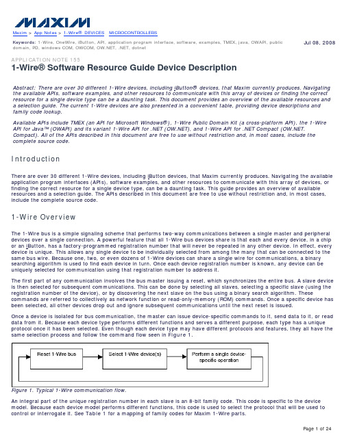
Maxim > App Notes > 1-Wire® DEVICES MICROCONTROLLERSJul 08, 2008 Keywords: 1-Wire, OneWire, iButton, API, application program interface, software, examples, TMEX, java, OWAPI, publicdomain, PD, windows COM, OWCOM, , .NET, dotnetAPPLICATION NOTE 1551-Wire® Software Resource Guide Device DescriptionAbstract: There are over 30 different 1-Wire devices, including iButton® devices, that Maxim currently produces. Navigating the available APIs, software examples, and other resources to communicate with this array of devices or finding the correct resource for a single device type can be a daunting task. This document provides an overview of the available resources and a selection guide. The current 1-Wire devices are also presented in a convenient table, providing device descriptions and family code lookup.Available APIs include TMEX (an API for Microsoft Windows®), 1-Wire Public Domain Kit (a cross-platform API), the 1-Wire API for Java™ (OWAPI) and its variant 1-Wire API for .NET (), and 1-Wire API for .NET Compact (. Compact). All of the APIs described in this document are free to use without restriction and, in most cases, include the complete source code.IntroductionThere are over 30 different 1-Wire devices, including iButton devices, that Maxim currently produces. Navigating the available application program interfaces (APIs), software examples, and other resources to communicate with this array of devices, or finding the correct resource for a single device type, can be a daunting task. This guide provides an overview of available resources and a selection guide. The APIs described in this document are free to use without restriction and, in most cases, include the complete source code.1-Wire OverviewThe 1-Wire bus is a simple signaling scheme that performs two-way communications between a single master and peripheral devices over a single connection. A powerful feature that all 1-Wire bus devices share is that each and every device, in a chip or an iButton, has a factory-programmed registration number that will never be repeated in any other device. In effect, every device is unique. This allows any single device to be individually selected from among the many that can be connected to the same bus wire. Because one, two, or even dozens of 1-Wire devices can share a single wire for communications, a binary searching algorithm is used to find each device in turn. Once each device registration number is known, any device can be uniquely selected for communication using that registration number to address it.The first part of any communication involves the bus master issuing a reset, which synchronizes the entire bus. A slave device is then selected for subsequent communications. This can be done by selecting all slaves, selecting a specific slave (using the registration number of the device), or by discovering the next slave on the bus using a binary search algorithm. These commands are referred to collectively as network function or read-only-memory (ROM) commands. Once a specific device has been selected, all other devices drop out and ignore subsequent communications until the next reset is issued.Once a device is isolated for bus communication, the master can issue device-specific commands to it, send data to it, or read data from it. Because each device type performs different functions and serves a different purpose, each type has a unique protocol once it has been selected. Even though each device type may have different protocols and features, they all have the same selection process and follow the command flow seen in Figure 1.Figure 1. Typical 1-Wire communication flow.An integral part of the unique registration number in each slave is an 8-bit family code. This code is specific to the device model. Because each device model performs different functions, this code is used to select the protocol that will be used to control or interrogate it. See Table 1 for a mapping of family codes for Maxim 1-Wire parts.Information Business Unit's (BU's) software libraries.¹These devices are no longer recommended for new designs.API FundamentalsThe different APIs for communicating with 1-Wire devices have common features that reflect the fundamental communication issues arising from the protocol. Figure 2 outlines the common groupings of the functions for the different APIs. Sincemost 1-Wire devices have memory, the memory I/O functions are treated as a common API group although the functions donot apply to all devices. All other nonmemory specialty functions are lumped into the device-specific device grouping.The typical sequence to use these functions is outlined in Figure 3. The SESSION functions wrap around the communication calls to the device, which typically involve using a NETWORK function followed by a memory or DEVICE-specific operation.Figure 3. API usage flow.The nature of iButton communication is inherently 'touch.' This means that contact with the device is not always reliable. The iButton might be inserted into the reader and have intermittent contact during the read. Consequently a consistent methodology of error recovery must be rigorously followed. This usually entails doing retries when a spurious error is detected and utilizing CRC checks in data communication. The file I/O functions in the APIs use a standard file structure detailed inthe 1-Wire File Structure section of application note 114, "1-Wire File Structure." This structure uses a CRC16 on every page of data to quickly verify the validity of the data being read. Most of the 1-Wire API functions have little or no automatic retries. The retries are under application control. See the application note 159, "Ultra-Reliable 1-Wire Communications," for methodology of error recovery and risk assessment in doing 1-Wire communication.API SelectionThere are principally five different APIs that are considered in this document. The APIs operate on different platforms, use different languages, and have different capabilities. Table 2 displays these five APIs with a brief description, and Table 3 maps the operating system with the available APIs divided by language.Table 2. API Descriptions1-Wire Public Domain PD A completely open-source public domain API written in C and designed to be portable across multiple PC operating systems, handheld operating systems, and microcontroller platforms. For PC platforms, it supports all 1-Wire adapters (masters) through native driver libraries on Microsoft Windows and specific 1-Wire adapters (DS9097U serial and DS9490 USB adapters) on other PC operating systems using cross-platform libraries.1-Wire API for Java OWAPI Completely open-source, high-level Java API that supports almost ALL 1-Wire devices. In addition to native 1-Wire master support, it also supports theDS9097U serial adapter and DS9490 USB adapter through cross-platform libraries.1-Wire API for .NET OWAPI code base compiled with J# for the Microsoft .NET Framework.1-Wire API for .NET Compact pact Compact .NET Framework for Windows CE machines or platforms that do not have the Microsoft Visual J#® Redistributable Package. It currently consists of just the low-level 1-Wire link and Network layer ported to C#.TMEX API TMEX Supports all 1-Wire master adapters on Windows platforms (32 and 64 bit). Provides link and file I/O functions, but no device functions. Drivers are closed source. This API is called by other APIs to obtain access to all ofthe 1-Wire adapter types.Table 3. API Operating System and Language CoverageWindows Vista®TMEX //pact PD OWAPI Windows Vista x64TMEX //pact PD OWAPI*TINI® is an embedded platform with a Java-based OS made by Maxim.¹No longer supported. Legacy driver downloads still available from the Maxim web site.The support of the individual device families also varies from API to API. Table 4 lists all of the currently available 1-Wire devices with flags indicating the available support in each API. The key for the Table 4 flags is located at the bottom. Note that the device cells without shading are considered fully supported by the API. A light-shaded cell indicates partial support, and dark-shaded cell indicates minimal support.owAttribute - Changes the attributes of a file.owChangeDirectory - Changes the current directory.owCloseFile - Closes a file.owCreateDir - Creates a directory.owCreateFile - Creates a file for writing.owCreateProgramJob - Creates a write buffer for logging EPROM programming pending jobs.owDeleteFile - Deletes a file.owDoProgramJob - Write the pending EPROM programming jobs.owFirstFile - Finds the first file in the current directory.owFormat - Formats the 1-Wire File Structure file system.owGetCurrentDir - Gets the current directory.owNextFile - Finds the next file in the current directory.owOpenFile - Opens a file for reading.owReadFile - Reads an opened file.owReadFile - Reads data from a file.owRemoveDir - Removes a directory.owReNameFile - Changes the name of a file.owWriteFile - Writes to a file that has been created.DoAtoDConversion - Does an A/D conversion on DS2450.ReadSwitch12 - Reads the state of the DS2406 switch.readCounter - Reads the counter value associated with a specific memory page on a DS2423 1-Wire chip....(too numerous to list all device-specific functions)Figure 4. PD API functions.Example 1 shows a PD code fragment that follows the API usage flow outlined in Figure 3. For simplicity, each device on the 1-Wire network is discovered during each pass through the work loop. A more sophisticated application could potentially find just one device type or perhaps select a device found in a previous search.int rslt, portnum=0, doing_work=1;char portString[50]; // set to platform appropriate port string// work loopwhile (doing_work){// acquire the 1-Wire Net (SESSION)if (owAcquire(portnum, portString)){// find all devices (NETWORK)rslt = owFirst(portnum, TRUE, FALSE);while (rslt){// do SOMETHING with device found (TRANSPORT/FILE/DEVICE)// . . .// find the next device (NETWORK)rslt = owNext(portnum, TRUE, FALSE);}// release the 1-Wire Net (SESSION)owRelease(portnum);}else{// Could not acquire 1-Wire network// . . .}// do other application work// . . .}Example 1. PD CODE example.Figures 5a and 5b list the C-language modules that make up each of the two sets of 1-Wire PD libraries. Also displayed are the 'TODO' functions that must be provided to port the library to a new platform. Several example platform link files that implement the 'TODO' functions are provided in the kit.owsesu.cowllu.c ds2480ut.c ds2480.hownetu.c crcutil.c (required to compile)mbappreg.c mbappreg.h mbee.c mbee.h mbee77.c mbee77.hmbeewp.c mbeewp.h mbeprom.c mbeprom.h mbnv.c mbnv.hmbnvcrc.c mbnvcrc.h mbscr.c mbscr.h mbscrcrc.c mbscrcrc.hmbscree.c mbscree.h mbscrex.c mbscrex.h mbscrx77.c mbscrx77.hmbsha.c mbsha.h mbshaee.c mbshaee.h owtrnu.c pw77.cpw77.h rawmem.c rawmem.howcache.c owfile.c owfile.h owpgrw.c owprgm.cad26.c ad26.h atod20.c atod26.c atod26.h cnt1d.chumutil.c humutil.h jib96.c jib96.h jib96o.c ps02.cps02.h sha18.c sha33.c shadbtvm.c shadebit.c shaib.cshaib.h swt05.c swt12.c swt12.h swt1c.c swt1c.hswt1f.c swt29.c swt29.h swt3a.c swt3a.h temp10.cthermo21.c hermo21.h time04.c time04.h weather.c weather.hioutil.c owerr.c findtype.c ownet.h screenio.c sprintf.ccrcutil.cProvided a SERIAL interface module that implements the following functions:BreakCOM* - Sends a 'BREAK' on the serial port for at least 2ms.CloseCOM - Closes the previously opened serial port. (optional for some platforms)FlushCOM* - Allows any pending write operations to complete and clear input buffer.msDelay* - Delays at least the specified number of milliseconds.msGettick - Returns an increment millisecond counter. (optional for some examples)OpenCOM - Opens the specified serial port for communication. (optional for some platforms)ReadCOM* - Reads a specified number of bytes from the serial port.SetCOMBaud - Changes the serial BAUD rate to the rate specified. (optional if needs overdrive)WriteCOM* - Writes a specified number of bytes to the serial port.* Minimum functions required for basic operation.Figure 5a. PD 'USERIAL' implementation.(see TODO)(see TODO)ownet.c crcutil.c (required to compile)Same as USERIAL implementation except 'owtrnu.c' is replaced by 'owtran.c'.Same as USERIAL implementation.Same as USERIAL implementation.Same as USERIAL implementation.Provided a LINK and SESSION interface module that implements the following functions:owAcquire - Acquires the 1-Wire net.owRelease - Releases the previously acquired 1-Wire net.owHasOverDrive - Indicates whether the adapter has overdrive capability.owHasPowerDelivery - Indicates whether the adapter can deliver power.owHasProgramPulse - Indicates whether or not EPROM programming voltage is available.owLevel - Sets the 1-Wire net line level to Normal (5V weak pullup), Power Delivery (5V strong pullup), or Program Level (12V EPROM programming level).owProgramPulse - Sends timed programming pulse for EPROM 1-Wire device writing.owReadBitPower - Reads 1 bit and then optionally supplies power.owReadByte - Receives 8 bits from the 1-Wire net by sending all 1's (0xFF).owSpeed - Sets the speed of the 1-Wire net to Normal (16kb) or Overdrive (142kb).owTouchBit* - Sends and receives 1 bit from the 1-Wire net.owTouchByte - Sends and receives 8 bits from the 1-Wire net.owTouchReset* - Resets all devices on the 1-Wire net and return result.owWriteByte - Sends 8 bits to the 1-Wire net and verifies the echo received matches.owWriteBytePower - Sends 8 bits of communication to the 1-Wire net and then supplies power.* Minimum functions required for basic operation.Figure 5b. PD 'GENERAL' implementation.InstallationThe 1-Wire PD API is a set of C modules, so there is no formal installation. As provided in the example builds, the required modules are compiled directly into the applications. This does not preclude developers from combining the modules into a loadable library such as a Windows DLL.Keep in mind that some builds require native 1-Wire adapter drivers or equivalent. As most OS platforms have built-in serial port drivers, the userial builds of the 1-Wire PD API do not need any other driver. However, for USB and parallel port 1-Wire adapter support, native or cross-platform drivers will need to be installed. References to the appropriate driver downloads are available in the documentation of the actual 1-Wire PD Kit builds available online.1-Wire API for Java (OWAPI) OverviewThe 1-Wire API for Java was designed from the ground up to be a very robust, highly object-oriented foundation forbuilding 1-Wire applications in Java. It extends the ability of programmers to develop portable, cross-platform software and shortens the time to market for their 1-Wire integrated products.The API consists of many Java classes and interfaces. One special group of Java classes in the 1-Wire API is the container (class OneWireContainer). Support for particular 1-Wire devices, including iButtons, is provided through containers. The API has over 30 different container types, representing most 1-Wire devices. Each container encapsulates and implements the functionality of an individual device.A container interacts with a 1-Wire device through a 1-Wire adapter class that represents a physical 1-Wire adapter (class DSPortAdapter). The instance of the adapter is produced from the provider class (class OneWireAccessProvider). The actualimplementations of the 1-Wire adapters vary from platform to platform, but they all have the same interface. Some platforms use native drivers, but most at least support the DS9097U-XXX serial adapters using RXTX (a cross-platform serial COM port API). This API is available from RXTX's web site.The 1-Wire API for Java Software Development Kit is available on the iButton web site. Like the 1-Wire PD Kit, the complete Java source to OWAPI is provided under a public-domain-style license.Figure 6 shows the typical object creation sequence for this API. The 'provider' creates an instance (or enumeration) of an'adapter,' which in turn can create instances of device 'containers.' Communication to the device is then performed almost exclusively through the container.Figure 6. OWAPI object creation.Figure 7 shows the common features of a container. A device that contains memory will create a memory bank instance for each memory bank. The memory is divided up into banks depending on the feature set of the bank. For example, one bank could be volatile while another is nonvolatile. Or, a bank could be general-purpose memory or it could be memory-mapped to change the functionality of the device.Figure 7. OWAPI ONEWIRECONTAINER features.Figure 8 shows the methods provided by the base OWAPI classes. The class or package is displayed in bold. Note that, because each container has high level methods to manipulate each device type, the LINK level methods in the adapter are not usually called directly.com.dalsemi.onewire.adapter.DSPortAdapterbeginExclusive - Acquires exclusive use of the 1-Wire net.endExclusive - Releases the exclusive lock on the 1-Wire net.com.dalsemi.onewire.adapter.DSPortAdaptercanBreak - Checks if a 1-Wire 'break' (long low) operation is supported by the adapter.canDeliverPower - Checks if 'strong-pullup' power delivery is supported by the adapter.canDeliverSmartPower - Checks if 'smart' power delivery is supported by the adapter. 'Smart' power delivery is the ability to sense when power consumption has reduced and automatically stop the power delivery.canFlex - Checks if flexible long-line communication timing is supported by the adapter.canHyperdrive - Checks if hyperdrive communication speed is supported by the adapter.canOverdrive - Checks if overdrive communication speed is supported by the adapter.canProgram - Checks if 12V EPROM programming voltage is supported by the adapter.dataBlock - Sends and receives a block of data to the 1-Wire net.getBit - Reads a single bit from the 1-Wire net.getBlock - Reads a block from the 1-Wire net by sending all (0xFF)s.getByte - Reads a byte from the 1-Wire net by sending all 1's (0xFF).getSpeed - Reads the current 1-Wire communication speed.putBit - Writes a bit to the 1-Wire net.putByte - Writes a byte to the 1-Wire net and verifies the echo is correct.reset - Resets all of the 1-Wire net devices.setPowerDuration - Sets the power delivery duration.setPowerNormal - Turns off the power delivery.setProgramPulseDuration - Sets the program pulse duration.setSpeed - Sets the 1-Wire communication speed.startBreak - Starts a break (low) on the 1-Wire net.startPowerDelivery - Starts the power delivery.startProgramPulse - Starts the program pulse.com.dalsemi.onewire.adapter.DSPortAdapterexcludeFamily - Excludes a family group from the search.findFirstDevice - Finds the first device on the 1-Wire net without auto container creation.findNextDevice - Finds the next device on the 1-Wire net without auto container creation.getAllDeviceContainers - Searches and finds all devices on the 1-Wire net with containers.getDeviceContainer - Gets a device container for the 'current' device found.getFirstDeviceContainer - Finds the first device and create a container for it.getNextDeviceContainer - Finds the next device and create a container for it.setNoResetSearch - Sets the 1-Wire net search to not issue a 1-Wire reset.setSearchAllDevices - Sets the 1-Wire net search to include all devices (remove alarm-only). setSearchOnlyAlarmingDevices - Sets the 1-Wire net search to only include alarming devices.targetAllFamilies - Sets the 1-Wire net search to include all devices (remove exclusions).targetFamily - Targets a particular family group in the 1-Wire net search.(also in com.dalsemi.onewire.container.*)isAlarming - Checks to see if the device is in an alarm state.isPresent - Checks to see if the device is present on the 1-Wire net.select - Selects the 1-Wire net device to ready it for a device-specific operation command.com.dalsemi.onewire.container.MemoryBankgetBankDescription - Returns a text description of the memory bank.getSize - Gets the size of the memory bank in bytes.getStartPhysicalAddress - Gets the starting physical address of the memory bank.isGeneralPurposeMemory - Checks if the memory bank is general purpose (not memory mapped).isNonVolatile - Checks if the memory bank is nonvolatile.isReadOnly - Checks if the memory bank is read-only.isReadWrite - Checks if the memory bank is read and write capable.isWriteOnce - Checks if the memory bank is write once, such as EPROM.needsPowerDelivery - Checks if this memory bank requires power delivery to write.needsProgramPulse - Checks if this memory bank requires program pulse to write.read - Reads the memory bank without interpretation (no packet structure).setWriteVerification - Sets the API to do an extra verification after writes.write - Writes the memory bank raw (no packet structure).com.dalsemi.onewire.container.PagedMemoryBankgetExtraInfoDescription - Gets a description of extra information associated with this bank.getExtraInfoLength - Gets the length in bytes of the extra information in each page.Example 2 shows a OWAPI code fragment that follows the API usage flow outlined in Figure 3. Like the PD code example in Example 1, each device on the 1-Wire network is discovered during each pass through the work loop, while a moresophisticated application could find just one device type or a previously found device.languages, such as C#, J#, and . For 1-Wire .NET examples, please refer to the appropriate software development kitWindows Platforms Supported by TMEXThe following Microsoft Windows platforms are supported by TMEX: Windows 2008, Windows 2003, Windows Vista, and Windows XP SP2. This includes both x86 (32-bit) and x64 (64-bit) operating system versions. Please note that if drivers for earlier Windows operating system versions are required, legacy versions of TMEX are available, though not actively supported, from Maxim's web site. Please download version 4.00 or below of the 1-Wire Drivers (which install the TMEX API libraries). 1-Wire Drivers installation packages can be found here: iButton: 1-Wire Drivers for Windows.Figure 9. TMEX API drivers and other API connectivity.Figure 10 lists functions provided by the TMEX API. Note that this API does not provide any nonmemory-device-specific functions.More information on the 1-Wire Drivers and OneWireViewer demo can be found on the iButton web site under "Software Resources."Other ToolsWhile the APIs discussed in this document represent a large part of the available resources for communication with 1-Wire devices, it is by no means the only resource. This section outlines some other available resources.Software Authorization APISoftware authorization is simply the locking of a software application to require the presence of a hardware token. The token in this case is an iButton connected to the user's workstation. The application polls for the presence and validity of the iButton before running. It can also continuously query while the application executes. In practice, any of the APIs outlined in this document can be used for this type of application; however, there are specific concerns that must be considered. External drivers present a weakness to the security by allowing a user to replace the driver and thereby defeat the lock. The software authorization API, built upon the 1-Wire PD Kit, has been developed specifically for this type of application and includes linkable modules instead of external drivers.The design of the Software Authorization API is centered on the simplest use cases possible, to make integration into the software programmer's existing code easy. There are three main services provided by the API:q Initializing a 1-Wire deviceq Authenticating the deviceq Clearing a device (so it is no longer a valid part of the system)Information on the 1-Wire Software Authorization Kit can be found on the iButton web site.Software Example Search EngineMaxim continually develops 1-Wire example software applications demonstrating the APIs described in this document. Examples that do not appear in the SDKs can be found by utilizing our online Software Example Search Engine. Many of these examples (with source code) are added to the search engine first (as a separate download) before being added to its respective SDK. The search engine can search for software examples by:q1-Wire device (Thermochron, SHA iButton, etc.)q Platform (Win32, Linux, TINI, etc.)q API (TMEX, 1-Wire Public Domain, 1-Wire .NET, etc.)q Programming language (C, Java, C#, Visual Basic, Delphi, etc.)Included in the search results are a description of the program and its appropriate download link.1-Wire Software Development Interest GroupIt is recommended that 1-Wire developers join the web-based 1-Wire Software Developer's Forum. The purpose of this group is to explore, discuss, and answer questions about developing applications, tools, and uses for the 1-Wire/iButton family of products. Maxim applications engineers monitor this forum to provide answers to questions posed by the group. Announcements about updates to the APIs and kit downloads are also posted to this group.Third PartyA large volume of third-party software is available for 1-Wire devices. Some are applications produced by Maxim authorized solutions developers (ASDs) for purchase with their solution. A complete list of ASDs and a solution locator are provided on the iButton site, as well as open-source projects on public forums like .DS1990R:QuickView-- Full (PDF) Data Sheet-- Free Samples DS1991:QuickView-- Full (PDF) Data SheetDS1992:QuickView-- Full (PDF) Data Sheet-- Free Samples DS1993:QuickView-- Full (PDF) Data Sheet-- Free Samples DS1994:QuickView-- Full (PDF) Data SheetDS1995:QuickView-- Full (PDF) Data SheetDS1996:QuickView-- Full (PDF) Data SheetDS2401:QuickView-- Full (PDF) Data Sheet-- Free Samples DS2404:QuickView-- Full (PDF) Data SheetDS2405:QuickView-- Full (PDF) Data Sheet-- Free Samples DS2406:QuickView-- Full (PDF) Data Sheet-- Free Samples DS2407:QuickView-- Full (PDF) Data SheetDS2408:QuickView-- Full (PDF) Data Sheet-- Free Samples DS2409:QuickView-- Full (PDF) Data SheetDS2411:QuickView-- Full (PDF) Data Sheet-- Free Samples DS2413:QuickView-- Full (PDF) Data Sheet-- Free Samples DS2415:QuickView-- Full (PDF) Data SheetDS2417:QuickView-- Full (PDF) Data Sheet-- Free Samples DS2422:QuickView-- Full (PDF) Data SheetDS2423:QuickView-- Full (PDF) Data SheetDS2430A:QuickView-- Full (PDF) Data SheetDS2431:QuickView-- Full (PDF) Data Sheet-- Free Samples DS2432:QuickView-- Abridged Data SheetDS2433:QuickView-- Full (PDF) Data Sheet-- Free Samples DS2450:QuickView-- Full (PDF) Data Sheet-- Free Samples DS2502:QuickView-- Full (PDF) Data Sheet-- Free Samples DS2505:QuickView-- Full (PDF) Data Sheet-- Free Samples DS2506:QuickView-- Full (PDF) Data Sheet-- Free Samples DS2890:QuickView-- Full (PDF) Data SheetDS28E04-100:QuickView-- Full (PDF) Data Sheet-- Free Samples AN155, AN 155, APP155, Appnote155, Appnote 155 Copyright © by Maxim Integrated ProductsAdditional legal notices: /legal。
1-wire总线接口应用

实验日期:
成绩:
1-wire
实验目的
1、理解1-wire总线的工作时序。
2、掌握DS18B20传感器的使用方法。
3、理解不同数码之间的转换方法。
实验仪器
单片机开发板、万利仿真机、稳压电源、计算机
实验原理
1、1-wire总线
近年来,美国的DALLAS公司推出了一项特有的单总线(1-Wire Bus)技术。该技术采用单根信号线进行数据传输。既可传输时钟,又能传输数据,而且数据传输是双向的,因而这种单总线技术具有线路简单,硬件开销少,成本低廉,便于总线扩展和维护等优点。
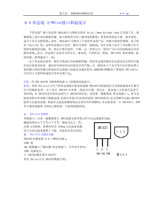
1-wire总线的读位时序如图4-25所示。首先把总线拉成地电平约8μS,然后IO口为高电平释放总线。主机(单片机)约在开始后15μS读IO数据,再等待读时序结束(约45μS),最后释放总线,准备读下一位。位与位之间间隔没有限制,但至少1μS以上。
图4-25 1-wire总线读位时序图
总线复位时序如图4-26所示。主机先把总线拉成低电平并保持480μS-960μS,然后主机释放总线(变成高电平)约15μS-60μS,DS18B20发出存在信号(低电平60μS-240μS),然后DS18B20也释放总线,准备开始通信。
此命令读暂存存储器的内容读开始于字节0,并继续经过暂存存储器直至第九个字节字节8CRC被读出为止。主机可以在任何时候发出一复位以中止读操作。
复制暂存存储器Copy Scratchpad [48h]
此命令把暂存存储器复制入DS18B20的E2PROM存储器,把温度存储器字节存贮入非易失性存储器。如果由寄生电源供电总线主机在发出此命令之后必须能立即强制上拉至少10mS。
Skip ROM(跳过ROM)[CCh]
在单点总线系统中,此命令通过允许总线主机不提供64位ROM编码而访问存储器操作来节省时间。如果在总线上存在多于一个的从属器件,而且在SkipROM命令之后发出读命令,那么由于多个从片同时发送数据会在总线上发生数据冲突漏极开路下拉会产生线与的效果。
用软件实现1-Wire-通信

摘要:在没有专用总线主机(如DS2480B、DS2482)的情况下,微处理器可以轻松地产生1-Wire 时序信号。
本应用笔记给出了一个采用…C‟语言编写、支持标准速率的1-Wire主机通信基本子程序实例。
1-Wire总线的四个基本操作是:复位、写“1”、写“0”和读数据位。
字节操作可以通过反复调用位操作实现,本文提供了通过各种传输线与1-Wire器件进行可靠通信的时间参数。
引言在没有专用总线主机的情况下,微处理器可以轻松地产生1-Wire时序信号。
本应用笔记给出了一个采用C语言编写、支持标准速率的1-Wire主机通信基本子程序实例。
此外,本文也讨论了高速通信模式。
要使该实例中的代码正常运行,系统必须满足以下几点要求:1. 微处理器的通信端口必须是双向的,其输出为漏极开路,且线上具有弱上拉。
这也是所有1-Wire总线的基本要求。
关于简单的1-Wire主机微处理器电路实例,请参见应用笔记4206:"为嵌入式应用选择合适的1-Wire主机"中的1类部分。
2. 微处理器必须能产生标准速度1-Wire通信所需的精确1µs延时和高速通信所需要的0.25µs延时。
3. 通信过程不能被中断。
1-Wire总线有四种基本操作:复位、写1位、写0位和读位操作。
在数据资料中,将完成一位传输的时间称为一个时隙。
于是字节传输可以通过多次调用位操作来实现,下面的表1是各个操作的简要说明以及实现这些操作所必须的步骤列表。
图1为其时序波形图。
表2给出了通常线路条件下1-Wire主机与1-Wire器件通信的推荐时间。
如果与1-Wire主机相连的器件比较特殊或者线路条件比较特殊,则可以采用最值。
请参考可下载的工作表中的系统和器件参数,确定最小值和最大值。
表1. 1-Wire操作图1. 1-Wire时序图表2. 1-Wire主机时序计算这些值的工作表可供下载。
代码实例下面代码实例都依赖于两个通用的'C'函数outp和inp,从IO端口读写字节数据。
1-Wire(单线)概述
会话 分时使用总线。这对于操作系统或几个进程或线程要求同时使用总线的情况下是非 常重要的。当多项操作在同一器件上运行而又不能被打断的时候,需要独占总线的使用 权。
链路 基本的 1-Wire 总线通信功能。所有的 1-Wire 总线的通信功能可以归结为:复位 所有的器件和读写位。这也包括设置总线电特性的功能,如提供专用的 EPROM 编程脉 冲或进行供电。
选定 1-Wire 器件
执行一个特定器件操作
每个受控器件的序列号的整数部分是一个 8 位的家族代码。这个代码对器件模型来说是 特定的。因为每种器件模型执行不同的功能,所以可以用代码来选择用于控制或者查询器件 的协议。表 1 是达拉斯半导体公司的器件型号的家族代码。
家族代码对照 表 1
家族代码
器件型号()iButton 封装
(DS1921Z)22 NhomakorabeaDS1822
23
(DS1973), DS2433
24
(DS1904), DS2415
26
DS2438
27
DS2417
28
DS18B20
DS2480B 1-Wire时序的理解及配置
摘要:DS2480B是带有UART主机接口的1-Wire®主机(驱动器)。
该驱动器专门为电源传输进行优化,并支持嵌入式应用中的高速模式。
DS2480B的特性之一在于其具有伸缩速率模式,允许设计者以标准速度配置1-Wire时序。
本应用笔记阐述了如何确定最佳时序配置以及如何用Windows®软件将设置参数写入芯片。
文章还将DS2480B与上拉电阻的驱动强度进行比较,详细描述见应用笔记3829。
附录一描述了如何确定最佳的配置参数。
附录二则给出了估算DS2480B可以驱动的从器件数目的算法,这取决于主机电气特性以及网络电缆的容性负载。
附录三讨论了网络过载的条件。
引言DS2480B是带UART主机接口的1-Wire主机(驱动器)。
该器件针对电源传输进行优化并支持嵌入式应用的高速模式,可以将主机从生成严格定时的1-Wire波形这一任务中解脱出来。
DS2480 B采用有源电路,缩短了时隙结束时的恢复时间。
图1给出了1-Wire驱动器部分的简化电路图。
图1. DS2480B 1-Wire驱动器的简化电路当1-Wire总线处于空闲状态时,DS2480B驱动器通过一个受控电流源提供上拉。
该电流源可被关闭(下拉期间),可提供弱上拉电流(下拉及空闲时IWEAKPU),或者提供一个有源上拉(上升沿时IACTPU)。
下拉电路(Q1)的压摆率可以通过软件调整。
Q2表示需要大电流的1-Wire从器件功能(如EEPROM编程或温度转换)所采用的供电电路。
Q2的功能在本应用笔记中未讨论。
为支持有效的布线配置,需要一个外部线路终端电阻RT (~100Ω)以尽量减小传输线路的影响,如反射、下冲和过冲。
然而,加入RT后会导致有源上拉在1-Wire总线完全充电之前过早关闭。
这是因为DS2480B检测的是其1-Wire引脚的电压,而非1-Wire网络从器件一侧的电压。
当1-Wire引脚电压到达内部门限值(典型值IACTPU ×RT =15mA × 100Ω = 1.5V)时,从器件一侧的电压将低于1-Wire引脚电压,差值为RT上的压降。
1-Wire总线协议应用
1-Wire总线协议应用作为一种单主机多从机的总线系统,在一条1-Wire总线上可挂接的从器件数量几乎不受限制。
为了不引起逻辑上的冲突,所有从器件的1-Wire总线接口都是漏极开路的,因此在使用时必须对总线外加上拉电阻(一般取5kΩ左右)。
主机对1-Wire总线的基本操作分为复位、读和写三种,其中所有的读写操作均为低位在前高位在后。
复位、读和写是1-Wire总线通信的基础,下面通过具体程序详细介绍这3种操作的时序要求。
(程序中DQ代表1-Wire总线,定义为P1.0,uchar定义为unsigned char)1 1-Wire总线的复位复位是1-Wire总线通信中最为重要的一种操作,在每次总线通信之前主机必须首先发送复位信号。
如程序1.1所示,产生复位信号时主机首先将总线拉低480~960μs然后释放,由于上拉电阻的存在,此时总线变为高电平。
1-Wire 总线器件在接收到有效跳变的15~60μs内会将总线拉低60~240μs,在此期间主机可以通过对DQ采样来判断是否有从器件挂接在当前总线上。
函数Reset()的返回值为0表示有器件挂接在总线上,返回值为1表示没有器件挂接在总线上。
程序1.1 总线复位uchar Reset(void){uchar tdq;DQ=0; //主机拉低总线delay480μs(); //等待480μsDQ=1; //主机释放总线delay60μs(); //等待60μstdq=DQ; //主机对总线采样delay480μs(); //等待复位结束return tdq; //返回采样值}2 1-Wire总线的写操作由于只有一条I/O线,主机1-Wire总线的写操作只能逐位进行,连续写8次即可写入总线一个字节。
如程序1.2所示,当MCS-51单片机的时钟频率为12MHz时,程序中的语句_nop_();可以产生1μs的延时,调用此函数时需包含头文件“intrins.h”。
- 1、下载文档前请自行甄别文档内容的完整性,平台不提供额外的编辑、内容补充、找答案等附加服务。
- 2、"仅部分预览"的文档,不可在线预览部分如存在完整性等问题,可反馈申请退款(可完整预览的文档不适用该条件!)。
- 3、如文档侵犯您的权益,请联系客服反馈,我们会尽快为您处理(人工客服工作时间:9:00-18:30)。
Java OWAPI OWAPI OWAPI OWAPI OWAPI
图 2. API 功能集
会话
分时使用 1-Wire 总线。这对于操作系统或几个进程或线程尝试同时使用同一总线的情况下是非常重要 的。当多项操作在同一器件上运行而又不能被打断的时候,需要独占总线的使用权。
链路
基本的 1-Wire 总线通信功能。 所有的 1-Wire 总线通信功能可以归结为:复位所有的器件和读写位。这 也包括设置总线电特性的功能,如提供专用的 EPROM 编程脉冲或进行供电。
是 执行其它 操作吗?
否 会话 释放 1-Wire 的独占式使用权
其它 处理申请表中的其它任务
AN155
iButton通信实质上是通过与其触头相接触来实现的。这意味着与器件的联系有时是不可靠的。iButton也可 能被安装到阅读器里,在阅读的时候弹出,从而必须有一个相容的纠错方法紧跟其后。当检测到虚假错误 时必须重发数据并在数据通信中进行CRC校验。API中的文件输入输出功能所利用的标准文件结构在 应用 笔记 114 (English only) 1-Wire File Structure中进行了详细说明。这种结构在每页数据上都使用CRC16, 以快速地校验所读数据的正确性。大多数 1-Wire API功能很少或者不能自动重发。重发受应用软件控制。 应用笔记 159 (English only)绝对可靠的 1-Wire通信 讲述了纠错方法和 1-Wire通信的风险评估。
图 3 概括了使用这些功能的典型顺序。‘会话’功能围绕着调用器件进行通信,具有代表性的是先使用一 个‘网络’功能,然后运行存储器或‘器件’的特定操作。
3
10/11/05
图 3. API 用法流程
会话 获取 1-Wire 的独占式使用权
网络 查找和/或者选定一个 1-Wire 器件
传输/存档/器件 选择做存储器还是器件的特定操作
API 的选择
本文主要列举了五种不同的应用程序接口(API)。这些 API 运行在不同的工作平台上,使用不同的语言, 具有不同的性能。表 2 简要地描述了这五种 API;表 3 说明了按语言划分的可利用 API 及其操作系统。
4
10/11/05
表 2. API 概述 API 1-Wire 公共文件资源
网络
查找和选择器件的网络功能。 每个 1-Wire 器件都有一个固定的序列号,作为它的唯一的网络地址。这 些功能可以通过链路层功能进行构造。在 1-Wire 器件数据资料中将其称为 ROM 指令,这是因为序列号 是只读的。还有一些 1-Wire 控制器包括一些内置功能,因为它们比通过链路功能进行构造有效得多。
传输
块通信和基本的存储器读/写功能。 这还包括存储器信息包读/写功能。这些功能是通过网络层和链路层 功能构造的。
文件
使用 1-Wire文件结构 (参考应用笔记 114,English only)的文档存储层功能。这些功能是通过网络层和 传输层功能构造的,且只对使用多页存储器的器件有效。
器件
专用器件的‘高层’功能。这些功能通常是通过网络、传输和链路类功能构造的,并执行诸如读取温度 值或设置开关状态等操作。
Thermochron 是 Dallas Semiconductor 的注册商标, Hygrochron 是 Dallas Semiconductor 的商标。 Java 是 Sun Microsystems 的商标。
2
10/11/05
AN155
API 基础
1-Wire 通信器件的不同应用程序接口 (API)有着许多共性,反映了协议的基本数据通信原理。图 2 是根据 不同 API 功能进行的分类。因为大多数 1-Wire 器件具有存储器,尽管存储器输入输出功能并不适用于所 有的器件,我们还是把它们视为一个通用 API 集。其它所有不具备存储器专用功能的划分为一类——专用 器件集。
TINI*
TMEX/OWCOM/ TMEX/OWCOM/ TMEX/OWCOM/ TMEX/OWCOM/ TMEX
()
PD PD PD PD PD PD PD PD PD PD PD
PD - 无 TINI 操作系统
( ) - 计划支持但尚未实现 *TINI® 是由Dallas Semiconductor研制的基于 Java操作系统的内置平台。
基于 Java 的 1-Wire API 基于.NET 1-Wire API 1-Wire COM
TMEX API
缩写 PD
OWAPI OWCOM TMEX
AN155
说明
源代码完全开放的C语言公共文件资源API,设计用于在多种PC操 作系统、手持设备操作系统和微控制器平台之间移植。对于PC平 台,通过本地驱动程序库在 32 位Microsoft Windows® 系统上支持 所有的 1-Wire适配器 (主机);利用跨平台库来支持其它PC操作系 统上的特定 1-Wire 适配器(DS9097U串行适配器和DS9490 USB 适 配器) 。 完全公开的、高级 Java API,支持几乎所有的 1-Wire 器件。除了 支持本地 1-Wire 主机外,它还可通过跨平台库来支持 DS9097U 串 行适配器和 DS9490 USB 适配器。 OWAPI 代 码 基 于 Microsoft 的 .NET 框 架 下 的 J# 。 对 于 紧 凑 型.NET 框架 (用于 Windows CE 机器),低级 1-Wire 链路层被转成 C#,可提供下载。 Windows 组件对象模型 (COM),OWAPI 的外壳,可以从标注语言 和诸如 Java 和 Visual Basic 的脚本语言中获得。注: OWCOM 依 赖于装有 Microsoft Java 虚拟机(MSJVM)、且 MSJVM 正常运行的 系统。Microsoft 不再支持 MSJVM。 在 32 位 Windows 平台上支持所有的 1-Wire 主适配器。提供链接 和文件输入输出功能,但不包括访问器件的功能。驱动程序是不公 开的资源。这种 API 可以被其它的 API 调用来访问所有类型的 1Wire 适配器。
1
10/11/05
表 1. 家族代码对照
家族代码
器件型号( ) – iButton封装
说明 (除非指明,否则存储器单位为位)
AN155
01 (十六进制)
(DS1990A), (DS1990R), DS2401, DS2411
只做 1-Wire 网络地址 (序列号)
02
(DS1991), DS1425
8 通道可编址开关
2C
DS2890
单路数字电位计
2D
DS2431
1024 位,1-Wire EEPROM
30
DS2760
温度传感器,电流,ADC
33
(DS1961S), DS2432
带 SHA-1 引擎的 1k EEPROM 存储器
37
(DS1977)
口令保护的 32kB (字节) EEPROM
3A
一旦一个器件被用于总线通信,主机就能向它发出特定的器件指令,对它进行数据读写。这是因为每类器 件具有不同的功能和不同的用途,而且一旦器件被选定,就有了唯一的协议。虽然每类器件具有不同的协 议和特征,但其工作过程却是相同的并且遵循如图 1 所示的工作流程。
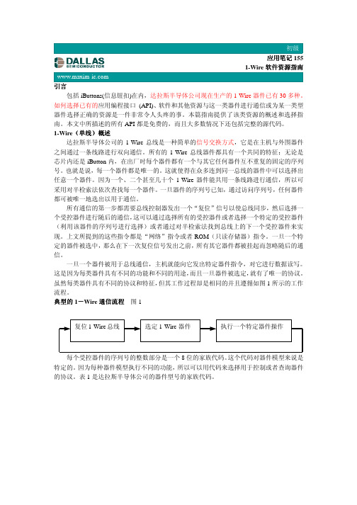
图 1. 典型的 1-Wire 通信流程
复位 1-Wire 总线
1C
DS28E04-100
1D
DS2423
4096位 EEPROM 存储器,2路可编址开关 具有外部计数器的 4kb NV RAM 存储器
1F
DS2409
用于子网的 2 路可编址耦合器
20
DS2450
4 通道 A/D 转换器 (ADC)
21
(DS1921), (DS1921H), (DS1921Z)
12
DS2406, DS2407
1kb EPROM 存储器, 2 路可编址开关
14
(DS1971), DS2430A
256 位 EEPROM 存储器和 64 位 OTP 寄存器
18
(DS1963S)
4kb NV RAM 存储器和 SHA-1 引擎
1A
(DS1963L)
具有写周期计数器的 4kb NV RAM 存储器
(DS2413)
双通道可编址开关
41
(DS1922L), (DS1922T), (DS1923), DS2422
高存储容量 Thermochron (温度)和 Hygrochron™ (湿度) 记录器
*该列表中并非 Dallas 的全部 1-Wire 器件 (家族),这些仅是 Automatic Information 事业部提供的软件库可直接支持的器件。
所有通信的第一步都需要总线控制器发出一个‘复位’信号以使总线同步,然后选择一个受控器件进行随 后的通信,这可以通过选择所有的受控器件或者选择一个特定的受控器件 (利用该器件的序列号进行选择) 或者通过对半检索法找到总线上的下一个受控器件来实现。上文所提到的这些指令都是‘网络’指令或者 只读存储器 (ROM)指令。一旦一个特定的器件被选中,那么在下次复位信号发出之前,所有其它器件都被 挂起而忽略随后的通信。
多键iButton,1152 位安全存储器
04
(DS1994), DS2404
4kb NV RAM 存储器和时钟,定时器,报警
05
DS2405
单一的可寻址开关
Байду номын сангаас06
(DS1993)
4kb NV RAM 存储器
08
(DS1992)
1kb NV RAM 存储器
09
(DS1982), DS2502
1kb EPROM 存储器
Thermochron® 温度记录器