超声波多普勒流量计说明书V5.00
超声波液体流量计简明使用手册

Panametrics公司TransPort®PT878手持式超声波液体流量计简明使用手册概述1.以Panametrics公司提供的TransPort®PT878英文手册为准,中文简明手册仅供参考。
2.超声波时差法流量计通过使用一对传感器,每个传感器通过流体发射和接收超声波信号。
当流体流动时,顺流方向信号的传播时间短于逆流方向,这个时间差正比于流体流速。
TransPort®PT878流量计测量这个时间差,结合设置的管径参数来计算流体的流速。
3.TransPort®PT878采用管外夹装式传感器,安装简便,无需破管与接触介质。
4.TransPort®PT878采用了受专利保护的声信号编码技术,从而极大提高了信噪比,这使得TransPort®PT878不仅适用于绝大多数的纯净液体应用,也为众多包含气泡、液滴或夹带固体颗粒等传统时差法原理无法测量的两相流体提供精确、无漂的测量。
PT878新特点♦可方便地按照您想看的格式显示您想看的数据∙超大液晶显示屏▫电致背景发光▫分块显示屏可显示1到4个参数∙支持多种语言♦为恶劣的工业操作条件设计,不受地域限制∙潜水型,防护等级IP67∙配有橡胶护罩和内置支架,可保护仪表电子部分♦可方便地记录超过100,000点以上的数据,无需杂乱的电缆就可将其下载至您的PC机∙红外通讯♦易于设置与操作∙可调的手带,携带方便∙下拉式菜单与软式按键让设置瞬间完成♦FLASH闪存∙不需更换EPROMs就可通过红外通讯口升级PT878的软件程序传感器安装和测量管路要求1.考虑到管路中流体可能存在的固体颗粒和气泡的分布,传感器应水平安装。
2.管路内流体需满管。
3.选择测量管路时应该避免选用流体自上向下流动的竖直管线。
4.传感器安装位置应远离弯头,变径,阀门,节流装置,安装点直管段的要求至少要满足前10D后5D(D为管线直径)。
5.为保证超声波发射和接收稳定,管线表面应该平整光滑,传感器表面和管径接触部不允许含有空气,必须涂抹耦合剂。
便携式多普勒超声波流量计使用说明
便携式多普勒超声波流量计使用说明示例文章篇一:哎呀,亲爱的朋友们,你们知道吗?今天我要给大家讲讲这个超级厉害的便携式多普勒超声波流量计!这东西看起来小小的,可作用大着呢!就像我们小小的身体里藏着大大的能量一样。
它的外观呀,不大不小刚刚好,能被我们轻松地拿在手里。
上面有一些按钮和屏幕,就像我们玩的游戏机,不过可别小瞧这些按钮和屏幕,它们可有大用处!当我们要用它的时候,第一步,得先把它打开,这就好比我们早上起床睁开眼睛,准备迎接新的一天。
然后呢,我们要根据测量的东西,设置好相应的参数。
这可有点像我们做数学题,得选对公式才能得出正确答案。
比如说,如果我们要测量水流,那就要把和水流相关的数值设定好。
你说这是不是很神奇?再然后,我们把这个流量计的探头放到要测量的地方。
这探头就像是我们的小侦察兵,去获取最准确的信息。
“哎呀,这能测准吗?”你可能会这么问。
放心啦!它可准啦,就像我们的眼睛看东西一样清楚准确。
在测量的过程中,我们要注意保持探头的稳定,不能乱动。
不然它就像被我们捣乱的小伙伴,会生气,给出不准确的结果哟。
测量结束后,数据就会显示在屏幕上啦。
我们可以清楚地看到各种信息,比如流速啦、流量啦等等。
这多方便呀!你看,这个便携式多普勒超声波流量计是不是很棒?它就像我们的好帮手,能帮我们快速又准确地获取各种测量数据。
我觉得呀,有了它,很多工作都会变得轻松又高效,难道不是吗?所以呀,大家都要好好了解它,学会使用它,让它发挥出最大的作用!示例文章篇二:哇塞!今天我要跟大家讲讲这个超厉害的便携式多普勒超声波流量计!你们知道吗?这玩意儿就像是一个神奇的小助手,能帮我们解决好多问题呢!想象一下,一条河流奔腾不息,我们想知道水在里面流得有多快,流量有多大。
这时候,便携式多普勒超声波流量计就派上用场啦!它的样子不大不小,拿在手里刚刚好。
上面有一些按钮和屏幕,可别小看这些哦!当我们要使用它的时候,第一步,先把它打开,就像打开一个神秘的宝箱一样。
多声道超声流量计使用说明书

多声道超声流量计使用说明书大连海峰仪器发展有限公司目 录1多声道超声流量计简介 (1)1.1测量原理 (1)1.2产品特点 (1)1.3产品构成 (1)2技术参数 (2)2.1准确度等级 (2)2.2工作环境要求 (2)2.3流量计防护等级 (2)2.4显示参数 (2)2.5输出 (2)2.6控制器(二次表)外形尺寸及重量 (2)3流量计安装 (2)3.1测量管(一次表)安装 (3)3.2控制器(二次表)安装 (3)3.3仪表箱(LOP)的安装 (3)3.4现场仪表盘内部接线 (6)3.5主电缆安装 (6)3.6压力变送器安装 (8)3.7接地方法 (9)3.8排水泵安装 (11)4控制器外观及操作键 (12)4.1控制器外观 (12)4.2操作键 (12)5显示器(LCD) (12)6功能与编制程序 (13)6.1功能菜单设定(MEAS FUNCTION) (13)6.2时间设定(TIME FUNCTION) (15)6.3累积流量清零,停电记录清零,存储数据清零 (15)6.4密码设定 (16)6.5查看累积流量,停电记录,错误编码 (16)6.6查看STAT菜单。
能显示各声道测量时间、各声道流速、声速和各声道工作状态 (17)6.7 通讯端口设置 (18)7维护及故障诊断 (19)7.1控制器 (19)7.2换能器 (19)7.3检测 (19)7.4其他 (19)7.5错误代码对查表 (20)8通讯协议及时时传送数据解析 (21)8.1叙述 (21)8.2缩语解释 (21)8.3通讯协议指令 (22)8.4数据内容定义 (22)附件:超级终端下载方法1 多声道超声流量计简介1.1 测量原理多声道超声流量计是采用时差法,通过测量超声脉冲在被测介质中的传播时间差得出的介质流速的速度式流量计。
可广泛用于原水、自来水、工业用水、冷却循环水、软化水、污水、海水等介质的流量测量。
1.2产品特点测量准确度高 “海峰”多声道超声流量计是通过对流速分布和面积分布的二重积分计算出面平均 流速和流量,在测量过程中不受雷诺数影响,因此可获得高准确度和高重复性。
多普勒流量计说明书
2.1、选择安装位置
注意:
选择合适的安装位置是保证测量可靠的基础,每个应用都有特殊性的,在每个 应用中,用户可以调整位置以求达到最佳的效果。 1、参见图 2.1(推荐安装位置) 2、根据下列原则选择安装位置 Ø 满管 Ø 液体流时管进(进口) Ø 流量计下流要 10 倍管径长的直管,上流要 5 倍管径长的直管。
点) 5. 按 ENTER 6. 按 SCROLL 键,直至一个方框出现在 ON 周围,到 LOGGER 的右边 7. 按 ENTER 8. 按 Flow 左侧的→键回到流量屏幕
图 2.12a – Log Screen
图 2.13a - Communications
第 9 页 共 26 页
Polysonics SX30 双频率超声波流量计
第 2 页 共 26 页
水平管线
深圳市 CHAMPION 系统有限公司
最佳位置 -3 点钟,9 点钟的位置 比较好的位置 -2 点钟,4 点钟的位置 -10 点钟,8 点钟的位置 可以位置 -3 点钟,4 点钟的位置 -9 点钟,8 点钟位置
垂直管线
图 2.2a-水平管线上探头安装方向
图 2.2b-在垂直管线上的探头安装方向
1.2、标准设备清单
注意:
下列设备包括在你定购的 Hydra SX30 DFD 流量计中: (1) Hydra SX30 便携式 DFD 流量计 (1) 已充满电的电池 (1) 便于携带的外壳 (2) 不可浸水的 DFD 探头 (2) 32 英寸管扎 (1) 67 英寸管扎 (1) 120VAC 电池充电器 (2) 带 BNC 接头的 16 英尺导线 (1) 3.5”软盘(含系统软件) (1) 声波耦合剂 (1) 5/8 英寸螺丝刀
超声波流量计说明书

§2.11 检查安装 ................. 52 §2.11.1 信号强度 ............ 52 §2.11.2 数据数量 ............ 53 §2.11.3 总传输时间、时差 .... 54 §2.11.4 传输时间比 .......... 54 §2.11.4 安装时注意的问题 .... 54
10
MKflo-2000F 系列中文版超声波流量计说明书
* 完备的输出信号包括集电极开路、频率信号 输出、4~20mA 电流环模拟输出等。带倍乘因 子(量程)的机内七位数长的正向、负向、 净流量及热量累积器独立工作,并可通过集 电极开路电路输出累计脉冲。
* 两路模拟输入可输入压力、温度液位信号。 配接温度变送器可实现热量测量。 * 用户选择标准校正曲线或用户实验校正曲线
何电路调整,使安装更容易简单。 * 可使用公制或英制单位,流量的单位可选用
几乎所有常用的中外通用单位,在带背光液 晶显示器上选择显示流量、流速、累积量及 日期时间等。 * 日、月、年流量累积功能可记录前 64 个运行 天、前 64 个运行月、前 5 个运行年的累积流 量;上、断电管理功能可记录前 64 次上电和 断电时间。 * 便携式流量计带有自动充电的机内电源,可 连续工作 8 小时。并备有外接直流电源输入插 座。
超声流量计说明书

This flowmeter is a clamp-on type ultrasonic flow meter based on transit-time measuring method.Making full use of the latest electronics and digital signal processing technologies, we realized a compact and light-weight design, and improved the accuracy and easiness to use while keeping with anti-bubble performance.The communication function (MODBUS: Option) is also applicable.)($785(61. Compact and light-weightThanks to the adoption of the latest electronics the flow transmitter size and mass are 1/3 of our traditional instrument.2. Full variety of sensorsThe flowmeter can be used with various types of sensors applicable for wide range of pipe size (ø13 to ø6000mm) and fluid temperature (-40 to +200°C).3. High accuracyThe flowmeter is designed for high accurary (better than ±1.0% of rate) by dynamic correction of fully-developed flow profile. Reynolds Number is calculated and a meter factor (K) is automatically applied for best accuracy at all flow velocities. Further, the adoption of new sound velocity measurement system permits measurements of fluids of unknown sound velocity. Moreover, affection from fluid temperature and pressure is negligible (Auto-Temp./Press. compensation).4. Excellent resistance against aerated flowFuji's unique ABM feature improves measurement reli-ability for different flow like slurries, sludge, raw sewage and bubble-contained flow (acceptable up to air bubble of 12% volume at 1m/s velocity).5. Quick responseWith the use of high-speed micro-processor suitedfor digital signal processing, the fast response time is realized.6. Multi-lingualThe following languages are supported for display:Japanese (Katakana), E nglish, German French, and Spanish.7. Excellent performance and easy operationLCD and function keys are allowing easy configuration and trouble shooting.− LCD with back light− Easy mounting of sensor− Trouble shooting− E asy operation with keypad on the front surface of the flow transmitter (FSV···S)63(&,),&$7,216Operational specificationsSystem configuration:Single-path system of a flow transmit-ter (Model FSV) and a detector (ModelFLS/FSG/FSD)Applicable fluid: Homogenous liquid where the ultra-sonic signal can be transmittedBubble quantity: 0 to 12vol% (for pipesize 50A, water, velocity 1m/s)Fluid turbidity: 10000mg/L max.Type of flow: Fully-developed turbulentor laminar flow in a full-filled pipeFlow velocity range:0 to ±0.3 ... ±32m/s6(5,(68/75$621,& )/2:0(7(5Detector (FSD32)Flow transmitter (FSV···S)Detector(FLSE12)(FLSE22)Detector (FSG)Detector (FSD22)Power supply: 100 to 240V AC +10%/-15%, 50/60Hz;or 20 to 30V DCSignal cable (between detector and converter):Coaxial cable (5m standard, 300m (60mfor popular detector (FLS)) max.)Heat resistance: 80°CInstallation environment:Non-explosive area without direct sun-light, corrosive gas and heat radiation. Ambient temperature:Flow transmitter: -20 to +55°CDetector: -20 to +60°C-20 to +80°C(for FLSE 2 2-A only) Ambient humidity:95%RHmax.Grounding: Class D (100 Ω)Arrester:Provided as standard at output andpower supplyApplicable piping and fluid temperature:Note 1: If the pipe material is PP or PVDF, select FSGS31, FSGS41 or FSGS5.Note that the wall thickness is 15mm or less for PP, and 9mm or less for PVDF. Note 2: For cast iron pipe, lining pipe, old steel pipe or others through which the ultrasonic signal could not be transmitted easily, select FSGS31,FSGS41 or FSGS50.Lining material: Tar epoxy, mortar, rubber, etc.* In case the lining is not glued to a pipe, the measurement may be impossible.Straight pipe length: Typically 10D for upstream and 5D for dowstream.(D: Pipe inner diameter)Refer to conditions on straight pipe for details(Japan Electric Measuring Instruments Manufacturers'Association Standard JEMIS-032).Note 3: If silicone-free grease is used as acoustic coupler, the fluid temperature range is0 to 60°C regardless of the detector.Note 4: When the 9th digit in the code symbol is “A”, the applicable piping diameter is up t o 150mm.Performance specificationsResponse time: 0.5s (standard mode)0.2s as selected (quick response mode)Power consumption:15VA max. (AC power supply)6W max. (DC power supply)Functional specificationsAnalog signal: 4 to 20mA DC (1 point)Load resistance: 1 kΩ max.Digital output:Forward total, reverse total, alarm,acting range, flow switch, total switchassignable arbitrarily(1) Mechanical relay contact (isolated,socket provided, arrester incorpo-rated)• Output: 1 point• Normal: Open/Close selectable• Contact capacity: 240V AC, 30V DC, 1A• Output frequency: 1P/s max. (pulsewidth: 50, 100, 200ms)(2) Transistor contact (isolated, open col-lector, arrester incorporated)• Outputs: 2 points• Normal: ON/OFF selectable• Contact capacity: 30V DC, 0.1A• Output frequency: 1000P/s max. (pulsewidth: 5, 10, 50, 100, 200ms)Digital input: 1 point (no-voltage contact) (option)/Set zero, Preset total assignableSerial communication (option):RS-232C equivalent or RS-485, isolated,arrester incorporatedConnectable quantity: 1 unit (RS-232C)/upto 31 units (RS-485: MODBUS)Baud rate: 9600, 19200, 38400bpsParity: None/Odd/Even selectableStop bits: 1 or 2 bits selectableCable length: 15m max. (RS-232C)/1km max. (RS-485)Data: Flow velocity, flow rate, forwardtotal, reverse total, status, etc.Display device: 2-color LED (Normal: green, Extraordi-nary: red)LCD with 2 lines of 16 characters andback lightIndication language: Japanese (Katakana)/English/French/German/Spanish (changeable)Flow velocity/flow rate indication: Instantaneous flow velocity, instantaneousflow rate indication (minus indication for reverse flow)Numerals: 8 digits (decimal point iscounted as 1 digit)Unit: Metric/Inch system selectableMetric systemInch system Velocitym/sft/sFlow rate L/s, L/min, L/h, L/d, kL/d, ML/d, m 3/s, m 3/min, m 3/d, km 3/d, Mm 3/d, BBL/s, BBL/min, BBL/h, BBL/d, kBBL/d, MBBL/d gal/s, gal/min, gal/h,gal/d, kgal/d, Mgal/d, ft 3/s, ft 3/min, ft 3/d, Kft 3/d, Mft 3/d, BBL/s, BBL/min, BBL/h, BBL/d, kBBL/d, MBBL/dNote: The ”gal” means USgal.Total indication: Forward or reverse total value indica-tion (negative indication for reverse direction)Numerals: 8 digits (decimal point iscounted as 1 digit)Unit: Metric/Inch system selectableMetric systemInch systemTotalmL, L, m 3, km 3, Mm 3, mBBL, BBL, KBBL gal, kgal, ft 3, kft 3, Mft 3,mBBL, BBL, kBBL,ACRE-ftConfiguration:Fully configurable from the 4-key pad (ESC, , , ENT)Zero adjustment: S et zero/Clear available External zero adjustment: Set zero available upon digital inputsettingDamping: 0 to 100s (every 0.1s) for analog outputand flow velocity/flow rate indicationLow flow rate cutoff: 0 to 5m/s in terms of flow velocity Alarm: Digital output available for Hardwarefault or Process faultBurnout: Analog output: Hold/Overscale/Under-scale/Zero selectable Flow rate total: Hold/Count selectable Burnout timer: 0 to 100s (every 1s)Bi-directional range: Forward and reverse ranges configu-rable independently. Hysteresis: 0 to 10% of working range Working range applicable to digitaloutputAuto-2 range: 2 forward ranges configurable indepen-dentlyHysteresis: 0 to 10% of working range Working range applicable to digitaloutputFlow switch:Lower limit, upper limit configurableindependentlyDigital output available for status atactuated pointTotal switch: Forward total switching point configu-rable Digital output available when actuated External total preset: Preset total settable upon contact inputsettingPhysical specificationsType of enclosure: Flow transmitter: FSV···S: IP66 FSV···H: IP67 (With large LCD) Detector: FLS (popular type): IP65 (When waterproot BNC con-nector is provided) FSG (common type): IP67 (Silicone compound is filledon the terminal part when wiring)FSG (submersible type): IP68 (submersible in water for 5days)FSD (small diameter and high tempera-ture type): IP52Mounting method:Flow transmitter: Mounted on wall or by2B pipeDetector: Clamped on pipe surfaceAcoustic coupler: Silicone rubber, silicone grease or silicone-free greaseNote: The acoustic coupler is a mediumthat eliminates a gap between detector and pipeProcure silicone grease (G40M), if necessary, as an optional accessory.Material: Flow transmitter: Aluminum alloy Detector:DetectorSensor housing Sensor cover SUS304Guide railPBT FLSE1SUS304PBT FLSE2Aluminum alloy + plasticPBT FSD22SUS304–PBT FSGS41FSGS5SUS304SUS304 + plasticPBT FSGS3––––SUS304 + aluminum alloySUS304FSD320($685,1* 35,1&,3/(With ultrasonic pulses propagated diagonally between the upstream and downstream sensors, flow rate is measured by detecting the time difference obtained by the flow offluid.Detector02817,1* 2) '(7(&725&21),*85$7,21 ',$*5$0(1) Single-path system (V method)Signal cable:FLY3 (applicable detector: FLS)• S tructure: Heat-resisting high-frequencycoaxial cable (3D2V)• S heath: Flame-resisting PVC• O uter diameter: ø5mm• T ermination: M3 amp terminal (flowtransmitter side) and BNC connector(sensor side)FLY8, FLY9 (applicable detector: FSG,FSD)• S tructure: High frequency coaxial cable(double shield)• S heath: Black flame-resisting PVC• O uter diameter: ø7.3mm• T ermination: M3 amp terminal (flowtransmitter side) and M4 amp terminal(FLY8).Note, however, that the detecterside of FSD22 and FSD32 is providedwith BNC connector (FLY9).• M ass: Approx. 90g/mDimensions: Flow transmitter FSV···S (IP66):H170×W142×D70mmFlow transmitter FSV···H (IP67):H277×W244×D95mmDetector:H50×W228×D34mm (FLSE1)H50×W348×D34mm (FLSE2)H90×W320×D53mm (FSD22)H46×W410×D50mm (FSGS3)H46×W54×D37mm (FSGS41)H67×W78×D84mm (FSGS5)H205×W530×D52mm(FSD32)Mass: Flow transmitter (indoor type):1.5kgFlow transmitter (outdoor type):4.5kgDetector:0.3kg(FLSE1)0.4kg(FLSE2)0.6kg(FSD22)0.6kg(FSGS3)0.3kg(FSGS4)1.2kg(FSGS5)1.6kg(FSD32)Provided as standard•Compatible model is PC/AT compatible instrument.•Operation is undefined for PC98 series (NEC).•Main functions: Software for Main unit parameter set-ting/change on PC•OS: Windows 2000/XP•Memory requirement: 125MB min.•Disk unit: CD-ROM drive compatible with Windows2000/XP•Hard disk capacity: Minimum vacant capacity of 52MBor moreNote: Optional communication board (specified at the5th digit of code symbols) and loader cable (ModelZZP*TK4J1236) are additionally necessary for RS232Cserial communication.Note: USB-RS232C converterFor PC that does not support RS-232C serial interface,a converter is necessary for connecting the PC andmain unit.USB-RS232C converter should be combined with theabove loader cable.<Recommendation>USB-CVRS9 (manufactured by Sanwa Supply)'(7(&725 6(/(&7,21 *8,'(Note: The ultrasonic signal cannot be transmitted easily when the classification of piping material is Px or the turbidity is high. In such a case, a preliminary check by a portable ultrasonic flowmeter is recommended.Px : PP , PVDFP : Plastic (PVC, etc.)M : Msetallic piping (steel pipe, copper pipe, aluminum, etc.)Classification ofpiping materials&2'( 6<0%2/<Flow transmitter>1YF S VY Description1234567891011121314(Destination) (4th digit)Standard (English)(Communication) (5th digit)NoneRS232C+DI RS485+DI(Use) (6th digit)Single measuring path (Power supply) (7th digit)AC100 to 240V 50/60Hz DC20 to 30V(Case structure) (9th digit)IP66IP67(Wire connection port) (10th digit)Weatherproof gland provided[G1/2 and G3/8 (internal threads)]Union (for pilica) with gland [G1/2 female screw](when "H" is specified 9th digit)(Combination with explosion-proof detector) (11th digit)None(Parameter setting) (12th digit)NoneSetting providedSetting provided + tag Tag(Mounting method) (13th digit)Pipe mount (if the 9th digit is S)Wall mountPipe mount (if the 9th digit is H)(Area) (14th digit)AmericaEurope, Middle East, Africa AsiaE Y AS H 14Y Y A BYY A B C A B CN E A<Detector, small diameter/high temperature type>112345678Small diameter sensor (ø13 to ø100) V method High-temperature sensor *1 (ø50 to ø400)V or Z method220S 1320F S D F S D Y *1:Note: As standard acoustic coupler, silicone rubber (KE-348W) isprovided for small diameter sensor, or grease for high temperature (KS62M) for high-temperature sensor.For turbid fluid or old pipe, cast iron pipe, mortar lining pipe orothers through which the ultrasonic signal could not betransmitted easily, use an optional guide rail (TK4C6164C1), and carry out mounting by Z method.Applicable diameter range V method: ø50 to ø250 Z method: ø150 to ø400&2'( 6<0%2/<Detector, popular type><Detector, common type>DescriptionType (5th and 6th digits)Small sensor 2MHz (ø50 to ø300)Small sensor 1MHz (ø50 to ø300)*2Middle sensor 1MHz (ø200 to ø1200)Large sensor 1MHz (ø200 to ø6000)Large sensor 0.5KHz (ø200 to ø6000)*2Acoustic coupler (10th digit)None *5Silicon rubber (KE348)Silicone-free grease (HIGH-Z) (Note 2)Silicone grease (G40M) (Note 2)Additional specification (11th digit)None Tag plateWire rope for mounting (12th digit)Specify it in the case of FSGS41 or FSGS5.NoneNominal diameter: up to ø500mm Nominal diameter: up to ø1000mm Nominal diameter: up to ø1500mmNominal diameter: up to ø3000mm Nominal diameter: up to ø6000mm 1F S G SY Y 112345678910111213Y A B C 3231415150Y AY A B C D EV methodV or ZmethodCan be specified only for FSGS5*2:*3:*5:For aging pipes, cast iron pipes or mortar-lined pipes that interruptsthe propagation of ultrasonic signals, select FSGS31 or FSGS50.Procure type FLY for the signal cable.Silicone rubber (KE-348W) is provided as a standard accessory to fillthe wiring mold. (It can also be used as an acoustic coupler.)If an additional acoustic coupler is required, select one among A, B and C.<Detector, submersible type>Description1F S G SA 112345678910111213A CBCDEFGH J K L M N P Q R Z3231415150Y AY A B C D EDedicated signal cable (9th digit)10m 20m 30m 40m 50m 60m 70m 80m 90m 100m 110m 120m 130m 140m 150mSpecified length(Contact us if length is more than 150m. Max. length is 300m.)Type (5th and 6th digits)Small sensor 2MHz (ø50 to ø300)Small sensor 1MHz (ø50 to ø300)*2Middle sensor 1MHz (ø200 to ø1200)Large sensor 1MHz (ø200 to ø6000)Large sensor 0.5KHz (ø200 to ø6000)*2Acoustic coupler (10th digit)Silicon rubber (KE348)Silicone grease (G40M) (Note 2)Additional specification (11th digit)None Tag plateWire rope for mounting (12th digit)Specify it in the case of FSGS41 or FSGS5.NoneNominal diameter: up to ø500mm Nominal diameter: up to ø1000mm Nominal diameter: up to ø1500mmNominal diameter: up to ø3000mm Nominal diameter: up to ø6000mm V methodV or ZmethodCan be specified only for FSGS5*2:For aging pipes, cast iron pipes or mortar-lined pipes that interruptsthe propagation of ultrasonic signals, select FSGS31 or FSGS50.3F L S EDescription12345678910Type (4th, 5th and 6th digits)Small diameter sensor, 2MNz (ø25 to ø100mm)Small sensor, 2MHz(ø50 to ø225mm) (Note 1)Acoustic coupler (7th digit) (Note 2)NoneSilicone rubberSilicone-free grease1222Y A BY A Optional specification (10th digit)None TagY BFluid temperature range (9th digit)-20 to +100°C 0 to +120°CV methodNote 2:Normally select silicone rubber as acoustic coupler. Siliconerubber in tube (100g) is furnished. If you place an order for several units, 1 tube may suffice for every 5 units.Select silicone-free grease for semiconductor manufacturing equipment or the like that is vulnerable to silicone. Thesilicone-free grease is water-soluble and, therefore, cannot be used in environment exposed to water or on piping subjected to a condensation. Since the grease does not set, a periodic maintenance (cleaning, refilling every about 6 months at normal temperature) is necessary.Note 1: When the 9th digit in the code symbol is “A”,the applicable piping diameter is up to 150mm.&2'( 6<0%2/<Signal cable>• For detector FLSF 1DescriptionL Y12345678F 1DescriptionL Y12345678Type of sensor (4th digit code) (for FLS)Cable length (5, 6 and 7th digit) 5 m 10 m 15 m 20 m 25 m 30 m 40 m 50 m 60 mOthers (contact us)005010015020025030040050060Z Z Z3 Type of sensor (4th digit)Small and large sensor (for FSG)Small dia and hight temp sensor (for FSD) Cable length (5,6 and 7th digit) 5 m 10 m 15 m 20 m 25 m 30 m 35 m 40 m 45 m 50 m 55 m 60 m 65 m 70 m 75 m 80 m 85 m 90 m 95 m 100 m 110 m 120 m 130 m 140 m 150 mOthers (contact us)005010015020025030035040045050055060065070075080085090095100110120130140150Z Z Z89Note: Must be procured unless the sensor is a submersible type.• For detector FSG and FSDConditions on straight pipe(Note) The source : JEMIS-032( D : Inside diameter of pipe)287/,1( ',$*5$0 (Unit:mm)Flow transmitter : FSV···S (IP66)Flow transmitter : FSV···H (IP67)Detecter (type : FLSE 2) (popular type)U bolt (M8)(option)U bolt (M8)& output cable (PF1/2)cable (PF1/2)287/,1( ',$*5$0 (Unit:mm)Detector FSD22 (Small diameter sensor)D i s t a n c e b e t w e e n t w o Detector FSGS5 (Large sensor)Detector FSGS3 (Small sensor)Detector FSD32 (High-temperature sensor)(Common type)(Submersible type)(Common type)(Submersible type)287/,1( ',$*5$0 (Unit:mm)Signal cable : FLY3 (For FLS)Signal cable : FLY8 (For FSG)Signal cable : FLY9 (For FSD)Loader cable : ZZP*TK4J1236Detector FSGS41 (Middle sensor)(Common type)(Submersible type)&211(&7,21 ',$*5$0NameDrawing No.123456789ZZP*TK4C6164C1ZZP*TK4J1236C1ZZP*45231N5ZZP*45735N2ZZP*TK7M0981P1ZZP*TK7G7983C1ZZP*TK7N3827P8ZZP*TK7J1005P1ZZP*TK745007P1ZZP*TK464686C1ZZP*TK464686C2ZZP*TK464686C3ZZP*TK464686C6ZZP*TK464686C13Guide rail for high-temperature sensor PC Loader cable Silicon grease (G40M)Silicone rubber (KE 348W)Silicone-free grease (HIGH Z)High-temperature grease (KS62M)Fuse for AC power Fuse for DC powerWire rope for mounting the sensor Spring Wire ropeNomal diameter: up to ø500mm Nomal diameter: up to ø1000mm Nomal diameter: up to ø1500mm Nomal diameter: up to ø3000mm Nomal diameter: up to ø6000mmtransmitter432N 1L 43−21+DC20 to 30V4TXDR1321SHILD RS-485TXDR24TXD321DI1GND RXD RS-232CDI1Status input(DI)AC power supplyDC power supplyOptionStatus input(DI)Earth terminal (M4)AC100 to 240V50/60Hz*1) Only for double shield coaxial cable (type FLY8, 9)<Flow transmitter><Detector>6&23( 2) '(/,9(5<•Flow transmitter (provided with U-bolt and nuts for pipe mount)•Detector (provided with mounting fixture and acoustic coupler)*The acoustic coupler is option for popular type detec-tors.•Signal cable•CD-ROM (contains instruction manual, loader software),7(06 '(6,*1$7(' 25'(5,1*1. Detector code symbols2. Flow transmitter code symbols3. Signal cable code symbols4. For large sensor: Mounting pipe size5. Tag No. as necessary6. If parameter setting is specified, send back the attached parameter specification table duly filled.237,21$/ $&&(6625,(6Printed in JapanCaution on Safety*Before using this product, be sure to read its instruction manual in advance.Information in this catalog is subject to change without notice.Note1: When total pulse output has been selected for DO1, DO2 or DO3 specify total pulse value and total pulse width so that conditions 1 and 2 shown below are satisfies.* In the case of 2 ranges, perform calculations using either flow span-1 or flow span-2, whichever is greater.Condition 1 :1000 [In the case of DO1 and DO2]1 [In the case of DO3]Flow span-1*[m 3/s]total pulse value*[m 3]Condition 2 :Flow span-1*[m 3/s]total pulse value*[m 3]10002 × total pulse width [ms]。
多普勒超声波流量计使用说明书--印刷打印版080119
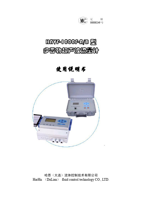
HNVF-1000F-A/B 型 多普勒超声波流量计 使用说明书
哈恩(大连)流体控制技术有限公司 HarHn (DaLian) fluid control techF-1000F-A/B 型多普勒超声波流量计使用说明书
目
录
第一章 简介(概述)-----------------------------------------------------------------------------------3 第二章 性能参数-----------------------------------------------------------------------------------------3 第三章 工作原理及应用--------------------------------------------------------------------------------4 §3.1、基本工作原理-----------------------------------------------------------------------------4 §3.2、流量计的特点-----------------------------------------------------------------------------4 §3.3、超声波流量计的典型应用----------------------------------------------------------------4 第四章 功能检查及安装指导--------------------------------------------------------------------------5 § 4.1、功能检查-----------------------------------------------------------------------------------5 §4.2、流量计的电气连接------------------------------------------------------------------------5 §4.3、传感器安装时的注意事项----------------------------------------------------------------6 §4.4、导声耦合剂--------------------------------------------------------------------------------8 §4.5、安装前的管道处理------------------------------------------------------------------------8 第五章 面板结构与说明--------------------------------------------------------------------------------9 §5.1、 显示区-------------------------------------------------------------------------------------10 §5.2、 调节区-------------------------------------------------------------------------------------10 §5.3、按键区-------------------------------------------------------------------------------------11 第六章 功能/参数窗口详解--------------------------------------------------------------------------12 §6.1、 流量计显示窗口一览表-------------------------------------------------------------------12 §6.2、 [流量计主菜单]窗口--------------------------------------------------------------------13 §6.3、 [显示功能菜单]窗口--------------------------------------------------------------------13 6.3.1、 [测量数值显示]窗口----------------------------------------------------------------14 6.3.2、 [查阅累积流量]窗口----------------------------------------------------------------15 6.3.3、 [查阅上断电时刻]窗口-------------------------------------------------------------16 §6.4、 [参数设置菜单]窗口 ------------------------------------------------------------------16 6.4.1、 [管道内径]窗口 -------------------------------------------------------------------17 6.4.2、 [最大流速]窗口 -------------------------------------------------------------------17 6.4.3、 [校准系数]窗口 -------------------------------------------------------------------18 6.4.4、 [阻尼系数]窗口 -------------------------------------------------------------------19 6.4.5、 [测量单位]窗口 -------------------------------------------------------------------19 6.4.6、 [低流速切除]窗口 -----------------------------------------------------------------20 6.4.7、 [累积流量显示倍率]窗口 --------------------------------------------------------20 §6.5、 [控制功能菜单]窗口 ------------------------------------------------------------------21 6.5.1、 [数据记录]窗口 -------------------------------------------------------------------21 6.5.2、 [继电器报警输出]窗口 -----------------------------------------------------------23 6.5.3、 [电流环输出]窗口 -----------------------------------------------------------------24 6.5.4、 [液晶背光选择]窗口 --------------------------------------------------------------25 6.5.5、 [设置日期与时间]窗口 -----------------------------------------------------------26 6.5.6、 [密码保护]窗口 -------------------------------------------------------------------26 6.5.7、 [显示语言选择]窗口 --------------------------------------------------------------27 - 1 -
超声波流量计说明书

一概述.....................................................错误!未定义书签。
§ 引言..................................................错误!未定义书签。
§ 工作原理...............................................错误!未定义书签。
§ 主板电气原理框图.......................................错误!未定义书签。
§ 特点...................................................错误!未定义书签。
§ 性能参数...............................................错误!未定义书签。
§ 用途...................................................错误!未定义书签。
二产品介绍...................................................错误!未定义书签。
§ 变送型超声波流量计/热量计..............................错误!未定义书签。
§ 经济型超声波流量变送器.................................错误!未定义书签。
§ 超声波流量/热量变送模块................................错误!未定义书签。
§ 固定分体式超声波流量计/热量计..........................错误!未定义书签。
§一体管段式超声波流量计/热量计..........................错误!未定义书签。
- 1、下载文档前请自行甄别文档内容的完整性,平台不提供额外的编辑、内容补充、找答案等附加服务。
- 2、"仅部分预览"的文档,不可在线预览部分如存在完整性等问题,可反馈申请退款(可完整预览的文档不适用该条件!)。
- 3、如文档侵犯您的权益,请联系客服反馈,我们会尽快为您处理(人工客服工作时间:9:00-18:30)。
前言非常感谢您选择本公司仪器!在使用本产品前,请详细阅读本说明书,请遵守本说明书操作规程及注意事项,并保存以供参考。
◆由于不遵守本说明书中规定的注意事项,所引起的任何故障和损失均不在厂家的保修范围内,厂家亦不承担任何相关责任。
请妥善保管好所有文件。
如有疑问,请联系我公司售后服务部门或地区客服中心。
◆在收到仪器时,请小心打开包装,检查仪器及配件是否因运送而损坏,如有发现损坏,请联系我公司售后服务部门或地区客服中心,并保留包装物,以便寄回处理。
◆当仪器发生故障,请勿自行修理,请联系我公司售后服务部门或地区客服中心。
◆提示:由于产品在不断更新,产品说明书和安装说明书不能保证跟最新的产品一致。
产品本身和使用说明如有所变化将不能通知到每一位客户,如有需要请直接跟我公司销售人员联系。
变化的部分包含但不限于以下部分。
1.产品的功能、结构、形状、颜色等。
2.软件的功能、结构、显示方式、操作习惯等。
注意1.传感器接线端子不允许外接其他信号线--只允许连接传感器,外接会使传感器采集的信号有偏差导致测量值不准。
2.在连接输出端口(包括4-20mA 、RS485)前建议在上位机和本仪表串口之间加相对应的隔离模块保护--如果未加而引起仪表的任何故障和损失均不在厂家的保修范围内,厂家亦不承担任何相关责任。
3.接线完成后请将上盖重新装回仪表上--防止潮气进入影响仪表使用寿命。
目录概述产品简介 (4)测量原理 (4)产品应用 (5)技术规格技术参数 (6)安装注意事项 (8)变送器安装 (9)传感器安装 (10)电气连接 (17)调试控制面板 (18)显示界面 (19)设置菜单 (20)设置菜单详解 (23)维护维护 (39)通信RS485通信 (40)常见问题常见问题 (45)快速安装指导1、安装变送器安装:参照说明书(第9页)中变送器的安装方式安装。
传感器安装:参照说明书(第10~16页)中传感器安装示图及安装方式安装。
2、电气连接分体式电气安装:参照说明书(第17~18页)中正确连接。
3、两点标定(出厂已用自来水标定,但由于水质不同,如现场有条件进行标定,建议客户需要根据实际测量水质进行标定,确保仪表测量的准确性。
)按下MODE键,进入到密码界面,输入参数设置密码“3000”,按SET键进入设置主菜单;按UP键移动光标到“3.校准”项,按SET键进入设置子菜单,按DOWN键移动光标到“4.两点标定”菜单项,按SET键进入界面,在低点和高点进行两点标定,按SET键保存(具体参照说明书第34-35页)。
一、概述产品简介本产品是在下水道里面或者不满管的管道内测量雨水或者污水流量的流量计,既不需要跟电磁流量计一样截开管道安装管段式传感器,也不需要使用截流装置,更不要安装固定的堰槽来控制水流从固定出口流淌。
测量原理多普勒流量计是以流速-水位运算法为基础,并采用了先进的流速测量仪和水位测量仪,从而确保测速和运算的准确性的一种新型智能化流量系统,系统采用多普勒原理测量流速,采用高精密的压力传感器测量水位,根据测出的实际水位、流速和已置入的渠道参数,按照预定的数学模型计算出渠道的流量。
产品有三个功能:测平均流速、测水深、测水温。
其中水温测量使用温度探头,温度探头不与水接触,紧贴仪器外包装材料顶部,需要置于水底一定时间后才能反映实际水温。
测水温的目的是校正超声波在水中的速度,并修正压力传感器所测得的水位值。
水深测量使用高精度压力传感器,置于仪器底部,其探头感应部位与水直接接触。
流速的测量是通过超声波探头(换能器)发射与接受超声波信号并做相应的计算处理而获得的:通过测得的平均流速及水位及断面尺寸,可求得断面流量。
产品应用超声波多普勒流量计是在管道、渠道或者河流内测量水的流量的设备,主要应用于以下范围:·洪涝灾害监测·污水排放·天然的河溪·市政给排水·水量流失/渗入监测·灌溉流程监测·河口和潮汐的研究·渔业/水利·海岸侵蚀研究·暗渠流程监测·道路排水监测·运河流程研究·江河流程监测二、技术规格变送器传感器仪表类型分体式测量种类流速、流量、水深、水温防护等级IP68用途在线式测量、在线式监测堰槽类型圆形,方形,矩形,梯形流速测量流速范围:0.05~5m/s (最小水深:15cm)分辨率:0.03m/s精度:测量流速的±2~4%水深测量水深范围:0.05~5m分辨率:0.01m精度:±2%温度测量温度范围:0℃~60℃分辨率:0.5℃流量范围10L/s~99999999m³/h瞬时流量分辨率:0.01m³/s误差:3%~6%供电电源AC220V 10%,50Hz功率5W信号输出模拟输出:4~20mA(双路可选)、负载750Ω数字输出:RS485(ModBus通信协议)开关输出:继电器高、低报警控制(双路可选)容量220VAC/2A菜单语言可中文、英文相互切换材质变送器为PC 传感器为POM被测水道类型管道,渠道,天然的溪流、河流液体酸碱度要求PH值在6~8之间,对传感器无腐蚀性液体温度要求0~50℃液体压力要求自然环境状态下,1个标准大气压三、安装注意事项◆传感器前端的两个圆形超声波收发装置应避免硬物撞击或划伤,在不用时应使用软套保护,当其上面附着异物时应用清水冲洗或软布轻察;底部的压力传感器位于网状透水孔内,其压力膜非常娇气,不得用硬物去接触,在仪器脱离水面不用时也应加以保护,在透水孔周围附着异物时应小心除去。
◆变送器应置于干燥处,在现场条件较潮湿时应注意防潮。
◆通信电缆线由于里面含有通气管,所以不能弯折过度,防止其折断;◆通信电缆线里面的通气管与探头里面的电路板相通,不能进水,安装时应使通气管末端开口朝下,防止潮气结水后沿管壁流入探头电路处;◆通信电缆线由探头引出水面时应尽量外套PVC管保护并沿途固定或沿支架的管内走线,使其避免直接受水力冲击而产生拉力,特别是水草较多的渠道当电缆线上挂草时会产生很大的拉力并有可能将电缆线拉断。
◆传感器前面的圆形超生波收发装置不能受到冲击及划伤;◆传感器安装好后要将其前面的超声波收发装置保护罩去掉,并将底部网状圆孔处的保护贴膜揭掉;◆变送器与通讯电缆线必须正确连接,否则会导致仪器损坏;◆仪器传感器应避免在太阳下长时间暴晒,以免温度太高而引起故障(传感器的温度不得超过70℃)。
变送器外形尺寸主视图侧视图背视图安装紧固方式一:变送器背后有三个定位孔,尺寸如“背视图”所示,其中上面的孔用于悬挂,下面两个孔用于螺栓固定。
方式二:变送器可以在专用滑轨上安装,用卡扣固定。
传感器外形尺寸现场安装方式总体安装图如下图1.安装说明水管多数为标准圆形,少部分是矩形或者梯形的。
对上游和下游直管道的理想要求:在传感器上游,要有管道宽度10倍的直管道,如果上游是闸门、水泵、要有管道宽度30倍的直管道。
在传感器下游,要有管道宽度5倍的直管道。
最小要求:在传感器上游,要有1.50米的直管道;在传感器下游,要有0.50米的直管道。
应安装于具有固定断面的渠道顺直段下游(顺直段越长测量精度越高),且这一距离范围内不得有过流阻挡物(如水闸、堰等),以保证探头前端水流流态的均匀稳定。
2.流速探头的安装在管道内,如果没有沉积物,我们把传感器安装在管道底部的正中央,正对着水流方向,这样能够测量到中间的流速,是最理想的安装位置。
无沉积物管道的安装位置如果有沉积物,把传感器安装在沉积物的旁边。
为了防止水流冲击变动传感器的安装位置,传感器底部有一个基座,专门用来固定在管道上。
同时,传感器要装在靠近窨井的里面,这样既便于安装,又利于维修和更换。
有沉积物管道的安装位置(1)流速探头安装位置:探头应尽量安装于靠近渠底,当渠底有杂质沉积及水草生长或滚动的卵石时,可抬高安装位置以避开渠底沉积物与水草覆盖探头或卵石冲撞探头;探头距渠底的具体高度最好为100mm-250mm,具体视渠道的最低测流水位而定。
当渠道水深较高且具有一定的最低水位时,为了安装方便只要将探头安装于最低水位以下0.5倍处即可。
探头在渠道横断面处的安装位置一般如下(渠宽在20m以下):对矩形断面安装于渠宽的0.15-0.2倍处;对梯形断面则安装于坡脚处;对于宽度较大的渠道,需安装2台或2台以上的探头,具体位置要视渠道宽度及横断面上的流态分布而定。
(2)安装方法:探头安装应完全水平于渠底(注意不是水平),同时保证与水流方向平行一致,探头前端(没有信号线的一端)逆水流方向并与水流方向夹角为180度,并且探头前端不得有阻挡物干扰水流流态,信号线(一体式时为通信电缆)从探头的下游引出。
对于可完全断水的渠道,可将固定探头的支架(固定支架可在当地定做,与探头连接部分最好用不锈钢板及螺栓)直接固定于渠底;对于不能完全断水且上游关闸后仍有较高水位不便水下作业的渠道,可将支架固定于渠臂上。
固定于渠臂上的支架有两种方式:简易支架与组合支架。
简易支架主要为一根弯曲的钢管或镀锌管,底部焊接一水平钢板以固定探头,竖立管通过钢片横翼固定于渠臂上;组合支架由底座与可拆卸部分组成,探头安装于可拆卸部分上,底座一次性固定安装于测流断面处(通过上游临时关闸降低水位后,用膨胀螺栓固定于混凝土边坡上),可拆卸部分通过水面上的螺栓与底座相连接固定,这样便于今后对探头的检修与更换。
3.水位探头的安装分体式水位探头最好安装于水位井中或渠道侧壁底部,压力传感器孔朝下,并高于淤积高度。
4.通信电缆的安装通信电缆应沿着渠底及渠壁引出水面,最好套PVC管进行保护并沿程固定;探头所自带的一段通信电缆线内有通气导管,因此注意不得将其弯折。
当通信电缆线引出水面后,可接普通的电缆线,此时应使通气导管开口方向朝下,并用透气胶布进行保护,防止水及异物进入通气管。
简易支架现场图传感器跟安装底座连接俯视图电气连接注意事项为了保证工作人员和仪表的安全,禁止带电操作!请按照如下顺序来完成电气连接:1、安装变送器和传感器2、拆下变送器接线盒,传感器电缆与变送器连接3、在变送器上4~20mA和继电器电缆连接4、在变送器上连接220V交流电缆5、确保接线正确后,安装变送器接线盒,用接线盒螺钉固定6、将220V交流电缆与现场220V交流电源相连。
分体式变送器接线端子图及说明三、调试分体式控制面板显示界面仪表开机后,首先显示的是测量模式。
在测量模式状态下,仪表显示的是瞬时流量测量值(三种测量单位可选m³/s、m³/h或L/s)、日期、时间、对应电流值和累计流量值。
设备状态位显示“R1”,继电器1报警设备状态位显示“R2”,继电器2报警按UP上键可进行界面切换。