FYLΦ19系列分层压力计使用说明书第二版
F5509 F6509差动压力计用户安装与维护指南(Ashcroft Inc. 2018)说明书

Differential pressure gauge, modelF5509/F6509 for industrial applicationsin the following configuration:• F5509/F6509 differential pressure gaugewithout switching contact• F5509/F6509 differential pressuregauge with inductive proximity switches• F5509/F6509 differential pressuregauge with electric contactsTable of contents:1 GENERAL REMARKS1.1 Purpose of this Manual (1)1.2 Symbols (1)1.3 Limits of liability (2)1.4 Copyright (2)1.5 Warranty (2)1.6 Manufacturer’s address, customer services (2)2 SAFETY (2)2.1 General sources of hazards (2)2.2 Use in accordance with intended purpose (2)2.3 Operator’s responsibility (2)2.4 Installation recommendations (2)2.5 Signs/Safety markings (2)2.6 Safety equipment (2)2.7 Environmental protection (2)3 TECHNICAL DATA (2)4 L ABELING ON THE DEVICE (2)5 CONSTRUCTION AND FUNCTION (3)5.1 Overview (3)5.2 Description of function (3)5.3 Description of components (3)5.4 Accessories (3)6 TRAN SPORT (3)6.1 Safety (3)6.2 Transport inspection (3)6.3 Storage (3)7 ASSEMBLY/IN STALLATION (3)7.1 Safety (3)7.2 Preparations (requirements for the installation location) 3 7.3 Mounting/Installation (3)7.3.1 Process connection (3)7.4 Starting up (4)7.5 Subsequent relocation of the gauge (by the customer) 48 SERVICIN G (4)8.1 Safety (4)8.2 Check on function, and recalibration (4)8.3 Cleaning and maintenance (4)9 D EFECTIVE OR FAULTY PRESSURE GAUGE (4)9.1 Safety (4)9.2 Conduct in the event of failure (5)9.3 When action is required to repair/replace the gauge59.4 Conduct following fault recertification (5)10 R EMOVAL, DISPOSAL (5)10.1 Safety (5)10.2 Removal (5)10.3 Disposal (5)11 APPEN DIX (5)11.1 Data sheet for differential pressure gaugeF5509/F6509 (5)11.2 CE Declaration of conformity (5)1 GENERAL REMARKS1.1 Purpose of This ManualThis Operating Manual contains fundamental and essential advice to be followed for the installation, operation and servic-ing of the device. It must be read before assembly and start-up of the device by the technician, the operator and the specialist personnel responsible for the device. This Operating Manual must be available at the point of use at all times. The follow-ing sections about general safety information (2) and also the following specific advice regarding the intended purposes (2.2) and through to disposal (10.3) contain important safety infor-mation which, if not followed, may result in risks for people and animals, or to property and buildings.1.2 SymbolsW arning!This indicates a possibly hazardous situationwhere failing to follow advice may result inrisks to people, animals, the environment andbuildings.Information!T his emphasizes key information for efficient,fault-free operation.1.3 Limits of liabilityRefer to Ashcroft standard terms of sale for limits of liability.1.4 CopyrightThis Operating Manual may only be copied and passed on as a complete document without the special permission of the publisher.1.5 Warranty For the product described here, we offer a warranty pursuant to our General Terms and Conditions on Delivery and Payment, Section 6: Liability for Defects.1.6 Manufacturer’s addresss, customer serviceAshcroft, Inc.250 East Main StreetStratford, CT 06614-5145, U.S.ATel: (203) 378 8281Fax: (203) 385 0408*****************2 SAFETY2.1 General sources of hazardsPressure gauges are pressurized parts where failure can result in hazardous situations. The selection of pressure gauge should be made in accordance with the rules set out in EN 837-2.2.2 Use in accordance with intended purposeThe devices are only to be used for the intended purpose as described by the manufacturer. The devices are used for direct display of differential pressure.The integrated switching elements are magnetic spring contacts or inductive proximity switches with a groove design, supplied by isolating switch amplifiers. If the set limit values are exceeded, the output circuits are opened or closed.For each use scenario, the corresponding set-up regulations must be respected. The use in explosion risk areas is not permitted.2.3 Operator’s responsibilitySafety instructions for proper operation of the device must be respected. They are to be provided by the operator for use by the respective personnel for installation, servicing, inspection and operation. Risks from electrical energy and from the released energy of the medium, from escaping media and from improper connection of the device must be eliminated. The details for this are to be found in the corresponding applicable set of regulations, such as DIN EN, UVV (accident prevention regulations) and in sector-specific instances of use (DVWG,Ex-. GL, etc.) the VDE guidelines and the regulations supplied by local utilities companies. The device must be taken out of service and secured against inadvertently being restarted, if the presumption is that risk-free operation is no longer possible (see Chapter 10: Faults). Altering the gauge by the customer is not permitted. This also applies to installation of spare parts. Possible conversions or alterations may only be carried outby the manufacturer. The operational safety of the device is only guaranteed when it is used for its intended purpose. The specification of the device must be adapted to the medium used in the plant. The limit values indicated in the technical data must not be exceeded. The safety information detailed in this Operating Manual, existing national regulations for accident prevention, and the operator’s internal regulations regarding working, operations and safety must be respected. The operator is responsible for all specified servicing, inspection and installation works being carried out by authorized and qualified specialists.2.4 Installation recommendationsThe gauge may only be installed and started up by specialist staff who are familiar with installation, start-up and operation of the product. Specialist staff are people who are able to assess the work assigned to them on the basis of their specialist training, their knowledge and experience and their knowledge of the relevant standards, and can identify possible risks.2.5 Signs/Safety markingsThe pressure gauge and its surrounding packaging carry markings. These markings show the article number, measurement range, maximum static pressure, maximum overload and manufacturer. The pressure gauge can be provided with additional signs and safety markings advising on special conditions:• Advice on the filling liquid• Advice on calibration• Oil-can deleted (if oxygen is used)2.6 Safety equipmentThis device is fitted with a (S3) solid front and rear wall (F6509) or (S1) blow plug (F5509) according DIN 16003, capable of being blown out. For the description, please refer to Chapter 5.3.4.The window uses multi-layer safety glass.2.7 Environmental protectionThis device may optionally contain a filling liquid (e.g. glycerin or silicone oil). The provisions set out in the REACH regulation on production and use of chemicals are to be respected, and the relevant safety data sheets from the manufacturers of the chemicals are available on our website for download. Electric contacts are offered as a gauge option. The provisions set out in the WEEE regulation EU directive 2012/19/EC on electrical and electronically equipment are to be respected, and the products are registered at the EAR under the number DE 26646349.3 Technical dataThe detailed technical information can be found in the documents in the Appendix, Chapter 11.4 Labeling on the deviceThe label with the serial number, type designation and process/ ambient temperature range is located on the outside ofthe housing. The materials identifier is encoded in the type designation.5. CONSTRUCTION AND FUNCTION5.1 Overview1 - Sensing diaphragm2 - Sealing/spring bellows3 - Connecting rod4 - Pointer mechanism5.2 Description of functionThe pressures to be compared, differential pressure, act ona flexible stainless steel diaphragm, which separates the two pressure chambers.The diaphragm is mechanically linked by a rigid connecting rod. When pressures are equal on both sides, the diaphragm is on zero position. When there is a difference in pressures the diaphragm is deflected away from the high pressure side, towards the lower pressure side, causing a displacement of the connecting rod. A precision mechanism translates the linear displacement of the diaphragm connecting rod to angular movement of the gauge’s dial pointer. The pointer’s displacement range of 270° corresponds to the full scale differential pressure.5.3 Description of components5.3.1 Scale with pointerThe differential pressure gauge is equipped with a dial face and pointer pursuant to DIN 16003, nominal size 100 mm or 160 mm.5.3.2 Instrument connectionThe instrument connection is located on the underside of the differential pressure gauge and can be male or female threaded process connection. Distance between ports is 37 mm, please consider this when selecting a 5 valve manifold.5.3.3 Vent plugThe vent plug for the housing is located on the top of the gauge case. If the nipple is pulled out, the housing is vented and the pressure which has built up in the housing due to the influence of temperature is discharged. With the plug closed, protection class IP 66 is achieved.5.3.4 Rear wall/plug with blow-out capabilityThe pressure gauge has a plug capable of blowing out onthe rear wall of the housing (Model F5509) or a rear wall capable of blowing out (Model F6509). These act as a safety feature pursuant to DIN 16003 and simultaneously allowfor temperature compensation for the housing, via a rubber membrane5.4 AccessoriesPlease contact the manufacturer regarding available special tools and accessories. (e.g.5 valve manifold).6 TRANSPORT6.1 SafetyThe pressure gauge should be protected against the effects of knocks and impacts. The device should only be transported in the packaging provided, to protect against glass breakage. The device should only be transported in a clean condition (free of residues of measuring media).6.2 Transport inspectionThe delivery must be checked for completeness and damage during transport. In the event of damage during transport, the delivery must not be accepted, or only accepted subject to reservation of the scope of the damage being recorded and, if necessary, contact Ashcroft for instructions.6.3 StorageThe differential pressure gauge must be stored in dry, clean conditions, within a temperature range of -20 to +80 °C, protected against direct exposure to sunlight and protected against impact damage7 ASSEMBLY/INSTALLATION7.1 SafetyTo ensure safe working during installation and servicing, suitable shut-off valves must be installed in the plant (see 5.4 Accessories), enabling the device:• To be depressurized or taken out of operation;• T o be disconnected from the pressure source for repair or inspection;• O r to enable function tests of the device to be performed “on site”.During the works to mount/install the gauge, the plant must be protected against being switched back on.7.2 Preparations (requirements for the installation location) • A check on suitability of the device for the medium to be measured, the scope of the measurement range and static pressure and of the protection against special conditions such as vibration, pulsation and pressure spikes.• A bracket must be installed to support the pressure gauge if the mountering process pipe is not able to provide adequate support.• T he installation location should be chosen such that the work-spaces for operating personnel are not located to the rear of the pressure gauge.7.3 Mounting/Installation7.3.1 Process connectionThe instrument is intended and factory adjusted for vertical mounting, pressure ports downward. When mounted in other orientation (max. ± 10°) the pointers’ zero position needs to be adjusted (see 7.4.1 Zero point adjustment).• C onnection to be made by authorized and qualified personnelonly.• U se only with the mechanical process connection provided – regarding the configuration, see order code on the device type label, with a matching threaded seal.• W hen connecting the device, the process piping must be depressurized.• T he process pipe must be installed on an incline so that: -for fluid measurement, no air pockets are created-for gas measurement, no water pockets are createdI f the necessary incline is not achieved, then at suitable points water separators or air separators must be installed.• T he pressure process pipe must be kept as short as possible and installed without sharp bends, to avoid a delayed response time.• T he instruments pressure ports are marked by “+” and “-” symbols: “+” port must be connected to the higher pressure“-” port must be connected to the lower pressure.• W ith liquid measurement media, the pressurized connection pipe must be degassed, since any gas bubble inclusions result in measurement error.• I f water is used as the measurement medium, the device must be frost-protected.Safety notice: Only mount using the correct open-jawed wrench, and do not twist the device itself.7.3.2 Electrical connection• C onnection to be undertaken by authorized and qualified specialist staff only.• T he electrical connection of the device is to be undertaken in accordance with the relevant regulations of the VDE and the regulations supplied by the local utilities company.• D isconnect the plant from the main supply before wiring electrical connections.• I nstall appropriate fuses upstream.7.4 Starting upThe precondition for start-up is proper installation of all electrical feed lines and metering pipes. All connecting lines must be installed so that no mechanical forces can act on the device. Before start-up, the seal on the pressurized connection line must be checked.7.4.1 Zero point adjustmentThe pressure gauges are supplied calibrated at the factory, so that as a rule there is no need for calibration at the installation point. For devices with Micrometer pointer (see. order code), zero pointer adjustment on site is possible. For this, proceed as follows:• Equalize pressure in both chambers.• C heck if internal pressure was built up in the case due to ambient temperature effect. Open valve (position B), wait for pressure relief and close valve again (position A)• L ift up on vent plug.• U se zero pointer adjustmentscrew to set the pointerto zero.• M ount vent plugFilled Models need to be vented beforecommissioning by opening the air valveon the upper side of instrument!7.4.2 Setting the electric contactsAn adjustable lock is fitted in the front panel of the pressure gauge. Using the removable adjustment key, the contacts mounted on the target value indicators can be set to anypoint on the range covered by the scale. For reasons relatingto accuracy of switching and the lifetime of mechanical measurement systems, the switch points should be positioned between 10% and 90% of the range.• P lace theadjustment keyon the axle of theadjustable lock.• P ress the axleinwards, until thecarrier arm gripsbehind the adjusterpin on the targetvalue indicator.• B y turning the key,adjust the targetvalue indicator tothe desired switchpoint.Swit c h 1 Swit c h 29.2 Conduct in the event of failureAll defective or faulty gauges must be taken out of service. If a repair is required contact inside sales.9.3 When action is required to repair/replace the gauge: Possible situations when action should be taken:• J erky or random movement of the pointer• P ointer does not set to zero for pressure less display • I ndications that the measurement system seal (diaphragm) has been breached (discoloration to dial display or of filling liquid)• B ent or loose pointer • C racked window• L eaks when the device is filled • D amage to housing• I ndications that the measurement system seal is imperfect (discoloration to dial display or of filling liquid)In these instances, repair or replacement of the pressure gauge is always required.9.4 Gauge repair/replacementSee Chapter 7.3 Mounting/Installation10 REMOVAL, DISPOSAL10.1 SafetyResidues of measuring media in and on removed gauges can constitute a risk to people, theenvironment and equipment. Adequate precautionary measures must be adopted. If necessary, the devices must be cleaned thoroughly (see advice in safety data sheets).10.2 Removal • W hen servicing the gauge, the pressure lines must bedepressurized, the electrical connections isolated from the mains supply, and the plant secured against being switched on again.• R emove the gauge using a suitable tool10.3 DisposalPlease help to protect the environment and dispose of or recycle the devices andcomponents used in accordance with the applicable regulations.11 APPENDIX11.1 Data sheet for Bourdon tube pressure gauge F5509/F6509Detailed data sheet is available from supplier’s website (see 1.6 Manufacturer’s address, customer services)This table refers to specific documents:Release the pressure on the axle, and remove the adjustment key.7.4.3 Contact function Function 1: C lose contacts with the indication rising in aclockwise direction. Function 2: O pen contacts with the indication rising in a clock-wise direction. Contact assignment:1st contact left target value indicator,2nd contact middle target value indicator, 3rd contact right target value indicator7.5 Subsequent relocation of the gauge (by the customer)Recommendation: Do not remove the pressuregauge from one pressure monitoring location to another , as there is a risk of the process media being mixed, with unforeseeable chemical reactions.8 SERVICINGThe device is maintenance-free. However, to ensure reliable operation and a long lifetime for the device, we recommend that it is checked regularly.8.1 SafetyWhen servicing the pressure gauge, the process lines must be depressurized. Special attention should be taken to ensure process pressure is not applied .8.2 Gauge performance and calibrationGauge performance and recalibration should be checked at regular intervals, depending on the application. The precise testing cycles should be adjusted in line with the operating conditions and ambient conditions. In the event of various device components interacting, the operating instructions for all other devices should also be taken into account.• C heck on display.• C heck on function, in conjunction with downstream components.• C heck of pressurized connection pipes for seal condition.• Check of electrical connections 8.3 Cleaning and maintenanceCleaning is carried out using a non-aggressive cleaning agent, with the ventilation valve closed and respecting the protection category of the device.9 W HEN ACTION IS REQUIRED TO REPAIR/REPLACETHE GAUGE9.1 SafetyDefective or faulty pressure gauges put the operational safety and process safety of the plant at risk, and can lead to a risk or injury to persons, the environment or the plant.Model Description Document F5509/ F6509SS differential pressure gauge F5509/F6509 G1.F5509K5500 Electrical contact devices for pressure & temp gauges.G1.K550011.2 CE Declaration of conformity。
Series 2-5000 Minihelic II 差分压力计说明说明书

Model A-434 A-609 A-497 A-489 A-362
Description Portable kit for Series 2-5000 Minihelic® II gage Air filter kit for Series 2-5000 Minihelic® II gage Mounting bracket for the Series 2-5000 Minihelic® II differential pressure gage 4˝ 303 SS straight static pressure tip with flange Stand-hang bracket, aluminum, for Minihelic® II gage
APPLICATIONS
• Room positive pressure sensing • Cabinet air-purging • Medical respiratory equipment • Air samplers • Electronic air cooling systems • Laminar flow hoods • Local indication on filter status • Face velocity on fume hood • Duct pressures
ORDER ONLINE TODAY! /Product/Series2-5000
©Copyright 2019 Dwyer Instruments, Inc. Printed in U.S.A. 11/19
DWYER INSTRUMENTS, INC.
DS-2-5000 Rev. 1
பைடு நூலகம்
DESCRIPTION
层压机说明书

12、线束和依博罗阀组的使用:极大的方便了设备的拆卸。
3
Apollo Precision(Fujian) Limited
三、主要性能
1.工作模式:手动、自动、半自动三种工作模式。自动模式工 作能实现自动入料、自动层压、自动出料作业;半自动模式工作能实 现单步手动入料、出料、自动层压作业;手动模式工作时能实现人工 入料、人工层压作业、人工出料作业功能。
2.外形尺寸: 15550×2400×2270mm; 3.加热板有效尺寸:1600×4600mm; 4.温控精度: ±1℃;温控范围:30℃~180℃。 5.加热板温度均匀性:±3℃ 6.加热方式:加热板采用热油加热方式。加热部分采用底功和 调功。加热方式即可以迅速地达到所需温度,又有效地节约了电能。 7.抽气速率:采用 1台 70升/秒的真空泵加一台 600升/秒的罗 茨泵,在密封良好的情况下,下腔室真空度在 2分钟内达到 200~20Pa。 8.在下腔室安装一个德国皮拉尼真空计,提高 0.1Pa到 400Pa 之间的测量精度。 9.工作台面高度:1000mm;最大开盖高度:300mm 10.电源:380V三相交流,74KW(整机功率小于 74KW,额定电 流小于 110A);电源线:三相五线制 35mm2。 11.使用环境:环境温度 0℃~50℃,相对湿度<90%,海拔高 度:2000m。
于负压状态时,禁止开盖! 关机时应先停加热后停油泵,严禁在 100℃以上关闭热油泵! 设备不需要工作,停止加热时,建议客户开盖散热!
1
Apollo Precision(Fujian) Limited
电子压力计使用说明书
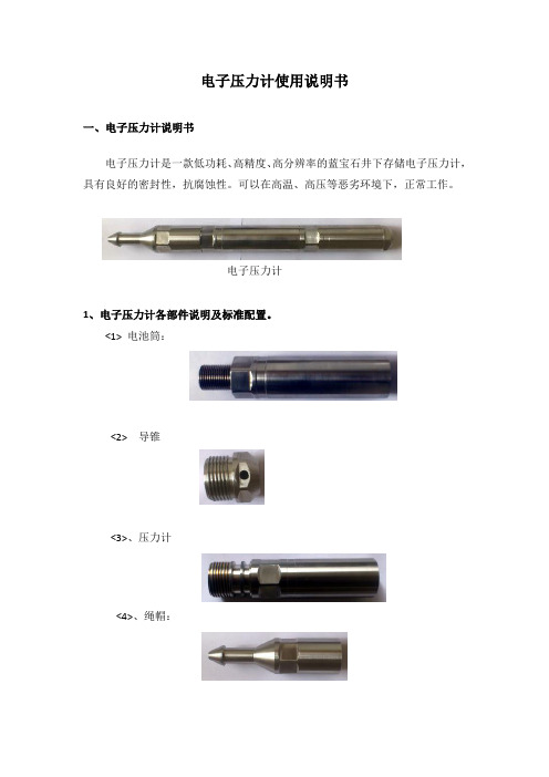
电子压力计使用说明书一、电子压力计说明书电子压力计是一款低功耗、高精度、高分辨率的蓝宝石井下存储电子压力计,具有良好的密封性,抗腐蚀性。
可以在高温、高压等恶劣环境下,正常工作。
电子压力计1、电子压力计各部件说明及标准配置。
<1> 电池筒:<2> 导锥<3>、压力计<4>、绳帽:<5>、电池<6>、连接线<7>、接口箱每箱电子压力计标准配置:两只电子压力计两个电池筒两个个导锥一个绳帽一个维修包(包括6个特别的O圈)一个USB接口箱(两只电子压力计配一个)标定证书操作软件两节节锂电池2、电子压力计工作模式电子压力计被设计成在低耗电量下工作,因此可以延长电池的寿命,以节省用户的开支。
<1> 采样模式:当电池接上压力计时压力计便进入了采样模式,而不是接口箱或连接线缆接上压力计时。
在正常操作的情况下,压力计会在现场被编程,然后运到井口,下井之前压力计应该是工作正常,且电池与压力计是连接在一起的,压力计执行相关的程序,这些程序是事先编辑好并保存在压力计里的。
<2> 休眠模式:当压力计没有采样时就会处于休眠状态(例如,两个采样点之间的时间)。
所有的压力计都被设计为:当一次采样完成之后,就会自动的转换到休眠模式。
<3> 通信模式:当接口箱和连接线把压力计连接到计算机上时,压力计就处于了通信模式。
通信模式用于压力计编程,下载数据文件,上传标定信息以及通过操作软件做一些与操作相关的其它事情。
3、装配和操作一旦编程被保存到压力计里,在操作能够发生之前,在压力计的装配上会有一个简单的步骤。
<1> 把电池连接到压力计之前,用我们的电池测试器检测它的电压。
任何一组新的标准的150℃AA锂电池的电量是3.6V-3.9V。
当电池的起始电压低于厂家所要求的值时,不要再使用该电池。
如果一组新电池的电压低于它所预期的值时,这也许是电池的钝化层所引起的。
YS活塞式压力计说明书

YS-6、60、250、600活塞式压力计说明书一、用途0.05级活塞式压力计(以下简称压力计)、用于检验0.2级活塞式压力计及精密压力表二、工作原理与基本结构压力计的工作原理基于活塞本身重量和加在活塞上的专用砝码重量,作用在活塞面积上所产生的压力与液压容器内产生的压力相平衡。
压力计系由检验泵和测量系统两部分组成。
见图:检验泵部分包括手摇泵(11)、油杯(9)及两个阀(6)和(7)。
在阀(6)和(7)上装有两端锁母,用以连接被检验的精密压力表。
测量系统主要由一个经过精密研磨后具有精确截面的活塞,活塞直接承受底盘上的砝码重量。
三、技术数据表1精确度等级基本误差限压力值在测量范围下限以下时压力值在测量范围内时0.02 测量范围下限的±0.02% 实际测量压力值的±0.02%0.05 测量范围下限的±0.05% 实际测量压力值的±0.05%YS-250、600活塞式压力计的承重杆(包括活塞头部)浸入工作液体浮力为5.6g.YS-6活塞式压力计,活塞底部与被校表中心液柱差H,表壳外径为φ150㎜,H=109㎜;表壳外径φ160㎜,H=119㎜,表壳外径φ250㎜,H=169㎜,其修正公式△P=Hγ,式中△P为液柱差产生的压力,γ=0.88g/cm3为变压器油的比重。
1、砝码2、指标板3、底座4、调整螺钉5、连接管部件6、7、8阀9、油杯10、水平仪11、手摇泵12、手轮13、测量系统参数单位值力值0.6MPa 6 MPa25MPa60 MPa测量上限MPa0.66256060测量下限MPa0.040.10.511活塞公称面积cm210.50.20.10.05底盘及活塞公称质量㎏0.40.5110.5产生产压力MPa0.040.10.511专用砝码公称质量㎏0.1;0.5 0.5;2.5 1;51;50.5;2.5产生的压力MPa0.010.050.010.50.5;2.51;51;5数量个6;104;114;94;111;11两端锁母M20×1.5M20×1.5M20×1.5M20×1.5M20×1.5重量㎏3565859575工作液体变压器油20℃时运动粘度9~12厘沲酸值不大于0.5毫克KOH/克癸二酸酯20℃时运动20~25mm2/s,酸值不大于0.05毫克KOH/克四、验收与保管1、用户收到装箱压力计,应先检查压力计包装是否完整;如有损伤,应即查明原因。
FYLΦ系列分层压力计使用说明书第二版
FYLΦ19 系列分层压力计使用说明书第二版西安思坦电子科技有限企业目录1FYL Φ 19系列分层压力计简介概括技术指标工作原理仪器构造压力计及其有关产品清单2压力计及其有关产品操作指南仪器各零件之间的连结方法直读、回放时的连结方法3试井操作指南试井前准备工作试井结束后工作步骤4压力计标定指南标定前准备工作标定结束后应做工作5压力计检定指南检定前准备工作5.2 检定结束后应做工作6新式压力计软件包简介软件安装基本操作说明7USB直读仪驱动安装1FYL Φ19系列分层压力计简介概括FYL Φ 19系列分层压力计主要用于丈量油井的流压和恢复压。
主要由投放和打捞短节、丈量短节、电池短节构成。
FYL Φ19系列分层压力计采纳先进的设计方法,硬件上采纳了超低漂移高精度的放大器、超稳固高精度压力传感器、低功耗高靠谱性CPU、多级保护型I 2C 总线 E2PROM、电源监督器,从硬件上保证了压力丈量的精度、长久稳固性和仪器的靠谱性;软件上采纳了多重安全保护举措和WATCHDOG技术,进一步保证了压力计的靠谱性。
技术指标FYL Φ 19系列分层压力计技术指标以下:仪器外径:工作外径Φ;最大外径Φ22mm仪器长度:234mm压力丈量范围:见型号及代码说明温度丈量范围:见型号及代码说明温度丈量精度:± ℃1.2.6 仪器工作温度范围:见型号及代码说明压力丈量精度:0.1%零点漂移:0.05%零点偏移:0.05%热零点偏移:0.05%热敏捷度偏移:0.05%敏捷阈:万分之零点八即<6KPa最大储存点数:20万最大丈量间隔:18小时最小丈量间隔:1秒1.2.16 仪器功耗:休眠时: <50uA工作时: <16mA仪器特色和工作原理FYL Φ 19系列分层压力计是丈量油水井压力值的仪器。
该仪器由传感器、记录和供电三部分构成。
传感器部分包含压力传感器和温度传感器两部分。
记录部分由单片机系统达成。
FYLΦ系列分层压力计使用说明书第二版
FYLΦ19系列分层压力计使用说明书第二版西安思坦电子科技有限公司目录1FYLΦ19系列分层压力计简介1.1 概述1.2 技术指标1.3 工作原理1.4 仪器结构1.5 压力计及其相关产品清单2压力计及其相关产品操作指南2.1 仪器各部件之间的连接方法直读、回放时的连接方法3试井操作指南3.1 试井前准备工作3.2 试井结束后工作步骤4压力计标定指南4.1 标定前准备工作4.2 标定结束后应做工作5压力计检定指南5.1 检定前准备工作5.2检定结束后应做工作6新型压力计软件包6.1 简介6.2 软件安装6.3 基本操作说明7 USB直读仪驱动安装1FYLΦ19系列分层压力计简介1.1 概述FYLΦ19系列分层压力计主要用于测量油井的流压和恢复压。
主要由投放和打捞短节、测量短节、电池短节组成。
FYLΦ19系列分层压力计采用先进的设计方法,硬件上采用了超低漂移高精度的放大器、超稳定高精度压力传感器、低功耗高可靠性CPU、多级保护型I2C总线E2PROM、电源监视器,从硬件上保证了压力测量的精度、长期稳定性和仪器的可靠性;软件上采用了多重安全保护措施和WATCHDOG技术,进一步保证了压力计的可靠性。
1.2 技术指标FYLΦ19系列分层压力计技术指标如下:1.2.1 仪器外径:工作外径Φ19.5mm;最大外径Φ22mm1.2.2 仪器长度:234mm1.2.3 压力测量范围:见型号及代码说明1.2.4 温度测量范围:见型号及代码说明1.2.5 温度测量精度:±0.5℃1.2.6 仪器工作温度范围:见型号及代码说明1.2.7 压力测量精度:0.1%1.2.8 零点漂移: 0.05%1.2.9 零点偏移: 0.05%1.2.10 热零点偏移: 0.05%1.2.11 热灵敏度偏移: 0.05%1.2.12 灵敏阈:万分之零点八即<6KPa1.2.13 最大存储点数:20万1.2.14 最大测量间隔:18小时1.2.15 最小测量间隔:1秒1.2.16仪器功耗:休眠时:<50uA工作时:<16mA仪器特点和工作原理FYLΦ19系列分层压力计是测量油水井压力值的仪器。
DFMO995FVRl 单压力计说明书
Do NOT install this unit within 2 ft. of electrical transformers, high strength electric motors or other electro-magnetic devises that could adversely effect the magnetic coupling between the Flow Indicator and the Piston Magnet.
The OMEGA ’“’Pneumatic In-Line Flowmeters monitor air flow rates to determine optimum performance, flow regulator settings, or pneumatic system performance. The FL27OOB, 67OOB, 77008, and 8700B Series feature direct reading scales for air flow. The FL2900, 6900, 7900, and 8900 multi-pressure scales (from 40 to 130 PSIG) mean accurate flow measurements can be made without the need for conversion calculations for pressure variations.
L An OMEGA Tedinologl.a Cmm,.myl/
压力表使用说明书
2. 构造及机能 波顿管压力表的一般构造及零件名称如附图所示。 其主要由接触液体部分、就是一端焊接在螺丝部位,另外一端封闭的波顿管和对管前端的运动进行放大的 机构部分(内机)、指针和刻度板以及箱体周边的部件所构成。 被测定体的压力从螺丝部位被传达到波顿管,使管的前端运动。管前端的运动经过棒杆使扇形面变动, 转动小齿轮,由嵌入小齿轮轴的指示针在刻度板上读取压力显示度。 液体接触部位、内机等的材质有多种可供选择,请根据需要选定。
3) 指针的显示度不稳定、或者指针的动作不圆滑的情况 内机的磨损或摩擦等 需要更换内机
注) 点捡时与压力基准器(或者标准压力表)比较,每年至少进行一次。 指针请使用拔针器拔掉。
主要零件的名称边(ຫໍສະໝຸດ 面)刻度盘 指针表壳
边(后面)
压力接口 (上)
罩壳
径向压力接口 (下)
轴向压力接口
3. 安装及使用 1) 波顿管压力表的安装,根据压力的情况和北侧体的种类,请选用适当种类的压力表.压力表的安装
拆卸,务必要使用螺丝扳手。 如果用压力表的外箱强力扭动,可以导致显示度错乱,请务必注意。 安装压力表请选在振动、潮气、灰尘和杂质等较少的场所。 另外、有必要在机器运转情况下进行更换 点检的时候,应安装水位管,如果是应用于蒸汽 空气等的 时,请安装排水管 排气口等,根据使用情况酌情考虑。
2) 波顿管压力表的压力测定上限 被测定压力没有变动的情况下,最高刻度的约 3/4。 被测定压力有变动的情况下,最高刻度的约 2/3。
4. 关于点检和保修 1) 指针不动的情况
内机的磨损或破损、小齿轮、扇形面的脱落、波顿管或者液体接触部位的泄漏 有必要由厂家进行修理
SMC XLF系列高压缩力低氢气阀门操作手册说明书
Doc. no.XL*****-OMJ0003-DHigh Vacuum L Type ValveXLF SeriesThank you for purchasing this SMC product.Be sure to read this Operation Manual carefully and understand its contents before operating this product to ensure the safety of the operator and this product.Please refer to the drawing and other informative documents for the construction and specifications of this product.Further, ensure your operating environment satisfies the requirements specified for the product.Keep this Operation Manual available whenever necessary.Safety Instructions - - - - - - - - - - - - - - - - - - - - - - - - - - - - 2 1. Product Specific Precautions 1 - - - - - - - - - - - - - - - - - - - - - - - - - - - - 4(Precautions on Design, Selection, Mounting, Piping, Wiring, Maintenance)2. Product Specific Precautions 2 - - - - - - - - - - - - - - - - - - - - - - - - - - - - 6(Maintenance parts)3. Specifications - - - - - - - - - - - - - - - - - - - - - - - - - - - - 74 Construction and Outer dimensions - - - - - - - - - - - - -- - - -- - - - - - - - - - - - 95. Period and scope of warranty - - - - - - - - - - - - - - - - - - - - - - - - - - - - 106. Parts replacement procedure - - - - - - - - - - - - - - - - - - - - - - - - - - - - 11Safety InstructionsThese safety instructions are intended to prevent hazardous situations and/or equipment damage. These instructions indicate the level of potential hazard with the labels of “Caution,” “Warning” or “Danger.”They are all important notes for safety and must be followed in addition to International Standards (ISO/IEC)*1), and other safety regulations.*1) ISO 4414: Pneumatic fluid power -- General rules relating to systems ISO 4413: Hydraulic fluid power -- General rules relating to systemsIEC 60204-1: Safety of machinery -- Electrical equipment of machines (Part 1: General requirements) ISO 10218-1992: Manipulating industrial robots -- SafetyCaution Caution indicates a hazard with a low level of risk which, if not avoided, could resultin minor or moderate injury.Warning Warning indicates a hazard with a medium level of risk which, if not avoided, could result in death or serious injury. DangerDanger indicates a hazard with a high level of risk which, if not avoided, will resultin death or serious injury.Warning 1. The compatibility of the product is the responsibility of the person who designs theequipment or decides its specifications.Since the product specified here is used under various operating conditions, its compatibility with specific equipment must be decided by the person who designs the equipment or decides its specifications based on necessary analysis and test results.The expected performance and safety assurance of the equipment will be the responsibility of the person who has determined its compatibility with the product.This person should also continuously review all specifications of the product referring to its latest catalog information, with a view to giving due consideration to any possibility of equipment failure when configuring the equipment.2. Only personnel with appropriate training should operate machinery and equipment.The product specified here may become unsafe if handled incorrectly.The assembly, operation and maintenance of machines or equipment including our products must be performed by an operator who is appropriately trained and experienced.3. Do not service or attempt to remove product and machinery/equipment until safety is confirmed.1.The inspection and maintenance of machinery/equipment should only be performed after measures to prevent falling or runaway of the driven objects have been confirmed.2.When the product is to be removed, confirm that the safety measures as mentioned above are implemented and the power from any appropriate source is cut, and read and understand the specific product precautions of all relevant products carefully.3.Before machinery/equipment is restarted, take measures to prevent unexpected operation and malfunction.4. Contact SMC beforehand and take special consideration of safety measures if the product is to be used in any of the following conditions.1. Conditions and environments outside of the given specifications, or use outdoors or in a place exposed to direct sunlight.2. Installation on equipment in conjunction with atomic energy, railways, air navigation, space, shipping, vehicles, military, medical treatment, combustion and recreation, or equipment in contact with food and beverages, emergency stop circuits, clutch and brake circuits in press applications, safety equipment or other applications unsuitable for the standard specifications described in the product catalog.3. An application which could have negative effects on people, property, or animals requiring special safety analysis.4. Use in an interlock circuit, which requires the provision of double interlock for possible failure by using a mechanical protective function, and periodical checks to confirm proper operation.Caution1.The product is provided for use in manufacturing industries.The product herein described is basically provided for peaceful use in manufacturing industries.If considering using the product in other industries, consult SMC beforehand and exchange specifications or a contract if necessary.If anything is unclear, contact your nearest sales branch.Limited warranty and Disclaimer/Compliance RequirementsThe product used is subject to the following “Limited warranty and Disclaimer” and “Compliance Requirements”.Read and accept them before using the product.Limited warranty and Disclaimer1.The warranty period of the product is 1 year in service or 1.5 years after the product isdelivered,whichever is first.*2)Also, the product may have specified durability, running distance or replacement parts. Please consult your nearest sales branch.2.For any failure or damage reported within the warranty period which is clearly our responsibility, a replacement product or necessary parts will be provided.This limited warranty applies only to our product independently, and not to any other damage incurred due to the failure of the product.3.Prior to using SMC products, please read and understand the warranty terms and disclaimers noted in the specified catalog for the particular products.*2) Vacuum pads are excluded from this 1 year warranty.A vacuum pad is a consumable part, so it is warranted for a year after it is delivered.Also, even within the warranty period, the wear of a product due to the use of the vacuum pad orfailure due to the deterioration of rubber material are not covered by the limited warranty. Compliance Requirements1.The use of SMC products with production equipment for the manufacture of weapons of mass destruction(WMD) or any other weapon is strictly prohibited.2.The exports of SMC products or technology from one country to another are govemed by the relevant security laws and regulation of the countries involved in the transaction. Prior to the shipment of a SMC product to another country, assure that all local rules goveming that export are known andfollowed.Warning●All models1. The material of the body and bonnet is A6063, and other metal components of the vacuumpart are made of SUS304. The sealing material of the vacuum part is FKM as standard, but this can be changed to other materials (refer to “How to Order”). Confirm whether the fluid to be used is compatible with the materials before use.Grease for vacuum is applied to the sliding part of the vacuum (Fluorine grease: Y-VAC2). 2. Select materials for the pilot pressure piping and fittings whose heat resistance is suitable forthe applicable operating temperature.●Models with auto switch1.Keep the temperature of the switch below 60oC.●With heater (thermistor)1.When using a model with a heater, a mechanism to prevent overheating should beinstalled.SelectionCaution●All models1. When controlling valve responsiveness, take note of the size and length of piping, as wellas the flow rate characteristics of the actuating solenoid valve.2. Actuating press should be kept within the specified range.0.4 MPa to 0.5 MPa isrecommended.3. Keep within the specified range of the pilot pressure.●High temperature type1. If using gases that cause a large amount of deposits, heat the valve body to prevent depositsin the valve.Mounting● All models1. In high humidity environments, keep the valve packed until the time of installation.2. For models with switches, secure the lead wires so that they have sufficient slack, withoutany unreasonable force applied to them.3. Perform piping so that excessive force is not applied to the flange sections. When there isvibration from heavy objects or attachments, etc., fix piping so that vibration will not apply torque directly to the flange section.4. Vibration resistance allows for normal operation of up to 30 m/s2 (45 to 250Hz), butcontinuous vibration may cause a decline in durability.Arrange piping to avoid excessive vibration or impacts.●High temperature type (temperature specification / H0 H4 H5)1. In models with a heater (thermistor), take care not to damage the insulation components of thelead wires and connector section.2. The set temperature for models with a heater should be established without any drafts or heat insulation. It will change depending on conditions such as heat insulation measures and the heating of other piping. Fine adjustment is not possible.3. When installing heater accessories or mounting a heater, check insulation resistance at the actual operating temperature. A current leakage breaker or fuse should be installed.4. If the valve is to be insulated, only the body should be insulated, excluding the bonnet part.5. In models with a heater, when the heater is in operation, the entire valve becomes hot. Be careful not to touch it with bare hands, as burns will result.1.Before mounting, clean the surface of the flange seal and the O-ring with ethanol, etc. 2. There is an indentation of 0.1 to 0.2mm in order to protect the flange seal surface, and it should be handled so that the seal surface is not damaged in any way.If the fluid or reaction product (deposit) may cause the valve to become unsafe, the valve should be disassembled, cleaned and re-assembled by an operator who has sufficient knowledge and experience (e.g. a specialist).1. When removing deposits from the valve, take care not to damage any part of it.2. Replace the bonnet assembly when the valve is approaching the end of its service life. * For details regarding endurance cycles, please reference Section 5 of this Operation manual titled Period and scope of warranty. (pages 10)3. If damage is suspected prior to the end of the service life, perform early maintenance.4. SMC specified parts should be used for service. Refer to the Construction / Maintenance parts table.5. When removing the valve seal and external seal, take care not to damage the sealing surfaces. When installing the valve seal and external seal, be sure that the O-ring is not twisted. (Refer to Section 6 Parts Replacement Procedure (pages 11 to 14) for details.)WarningSMC specified parts should be used for service. Refer to the construction drawing.1. Replace the bonnet assembly when changing the sealant material. Due to the differentmaterials used, changing only the seal may prove inadequate.Bonnet assembly/construction part number:1Temperature specifications IndicatorValve size16 25 40 50General use without XLF16-30-1 XLF25-30-1 XLF40-30-1 XLF50-30-1 with XLF16A-30-1 XLF25A-30-1 XLF40A-30-1 XLF50A-30-1High temperature without XLF16-30-1H XLF25-30-1H XLF40-30-1H XLF50-30-1H with XLF16A-30-1H XLF25A-30-1H XLF40A-30-1H XLF50A-30-1HTemperature specifications IndicatorValve size63 80 100 160General use without XLF63-30-1 XLF80-30-1 XLF100-30-1 XLF160-30-1 with XLF63A-30-1 XLF80A-30-1 XLF100A-30-1 XLF160A-30-1High temperature without XLF63-30-1H XLF80-30-1H XLF100-30-1H XLF160-30-1H with XLF63A-30-1H XLF80A-30-1H XLF100A-30-1H XLF160A-30-1H Note1) The magnet for auto switch is not provided. When the magnet for auto switch is necessary, add “-M9//” at the suffix of the part number.Note2) An auto switch for high temperature is available with a different part number.Note3) List the optional sealant material symbol after the model number, except for the standard sealant material (FKM: compound No. 1349-80).Note4) The bonnet assembly includes tha valve seal.External seal / Valve sealDescription ConstructionNo. MaterialValve size16 25 40 50External seal(3) Standard XLF16-6 XLF25-6 AS568-035V AS568-039V Special- - AS568-035 ** AS568-039 **Valve seal (2) Standard B2401-V15V B2401-V24V B2401-P42V AS568-227V Special B2401-V15 ** B2401-V24 ** B2401-P42 ** AS568-227 **Description ConstructionNo. MaterialValve size63 80 100 160External seal(3) Standard AS568-043V AS568-045V AS568-050V AS568-167V Special AS568-043 **AS568-045 ** AS568-050 ** AS568-167 **Valve seal (2) Standard AS568-233V B2401-V85V AS568-349V B2401-G155V Special AS568-233 ** B2401-V85 ** AS568-349 ** B2401-G155 **Note1) List the optional sealant material symbol after the model number, except for the standard sealant material (FKM: compound no. 1349-80).Note2) Refer to the Construction of each series for the construction numbers.Note3) We do not guarantee the quality if the seal material is changed by customer.Note1) Due to the different materials used, changing only the seal may prove inadequate.Barrel Perfluoro R is a registered trademark of MATSUMURA OIL Co.,Ltd.Kalrez R is a registered trademark of E. I. du Pont de Nemours and Company.Chemraz R is a registered trademark of Greene, Tweed & Co.,ULTIC ARMOR R is a registered trademark of NIPPON VALQUA INDUSTRIES, LTD. Model XLF-16 XLF-25 XLF-40 XLF-50 XLF-63 XLF-80 XLF-100 XLF-160 Flange (valve) size 16 25 40 50 63 80 100 160 Actuating type Normally closedFluid Vacuum of inert gasOperating temperature o C 5 to 60 (5 to 150 for high temperature type)Operating pressure Pa (abs) Atmospheric pressure to 1 x 10⁻⁵Conductance l/s Note 1 5 14 45 80 160 200 300 800LeakagePa・m3/s Internal 1.3 x 10⁻¹⁰ for the standard material (FKM)at ambient temperatures , excluding gas permeation External 1.3 x 10⁻¹⁰ for the standard material (FKM)at ambient temperatures , excluding gas permeationFlange type KF (NW) KF (NW) , K (DN)Main material Body: aluminum alloy, Main part: SUS304 and FKM (standard sealing material) Note 2Surface treatment for body Outside: hard anodized Inside: basis material Actuation pressure MPa(G) 0.4~0.7Air consumption cm3Note 3 for0.5MPa19 46 200 360 660 1350 3000 5150Port size M5 Rc 1/8 Rc 1/4 Weight kg 0.25 0.45 1.1 1.6 3 4.8 10 18 Note 1)The conductance is “molecular flow” measured with an elbow pipe which has the same dimension with each flange.Note 2) A seal sliding part and an external seal for vacuum use vacuum grease (Y-VAC2).Note 3) Air consumed by a reciprocating motion of a cylinder.3-2. Heater specificationsItem XL□-25 XL□-40 XL□-50 XL□-63 Rated voltage of the heater 90 to 240 ACVS y m b o l H4Heater assembly number - XLA25-60S-1 XLA25-60S-1 XLA25-60S-2 No. of heater assemblies - 1 pc. 1 pc. 1 pc.Initial power /Powerconsumption (W)100 VAC - 200/40 200/50 400/100200 VAC - 800/40 800/50 800/100H5Heater assembly number XLA25-60S-1 XLA25-60S-2 XLA25-60S-2 XLA25-60S-3 No. of heater assemblies 1 pc. 1 pc. 1 pc. 1 pc.Initial power /Powerconsumption (W)100 VAC 200/40 400/70 400/80 600/130200 VAC 800/40 1600/80 1600/80 2400/130Item XL□-80 XL□-100 XL□-160 Rated voltage of the heater 90 to 240 ACVS y m b o lH4Heater assembly number XLA25-60S-3 XLA25-60S-2 XLA25-60S-2 No. of heater assemblies 1 pc. 2 pcs. 3 pcs.Initial power/Powerconsumption (W)100 VAC 600/150 800/220 1200/350200 VAC 2400/150 3200/220 4800/350H5Heater assembly number XLA25-60S-2 XLA25-60S-2 XLA25-60S-2 No. of heater assemblies 2 pcs. 3 pcs. 4 pcs.Initial power/Powerconsumption (W)100 VAC 800/180 1200/300 1600/400200 VAC 3200/180 4800/300 6400/400 Note 1) Initial power and power consumption are nominal values.Note 2) Heaters are not available for the size 16 models.The heaters are PTC thermistor type design. Thesethermistors self regulate their temperature by switchingthe resistance at certain critical temperatures, so aseparate temperature controller is unnecessary.If the temperature of the PTC heaters fitted exceeds200o C, then it may fail. The maximum operatingtemperature for the valve is 150o C. If the heatertemperature is over 200o C or valve temperature is over150o C, please use thermostat to control the heaters toprevent overheating.With PTC type heaters, there is an initial surge ofcurrent (inrush current) after the power is supplied. These inrush current will reduce overtime. If multiple heater assemblies are used, the inrush current to the heaters will be magnified and care should be taken. When multiple heater assemblies or valves are used, do not apply power to the heater assemblies simultaneously. Keep approximately 30 seconds between applications of power to each heater assembly. This will allow for incremental spacing to prevent harmful large initial surge.4.hardened andnickelAAHφGBAuto switch(option)Model A B C D E Fn Fd G H XLF-16 40 103 38 1 - 30 - 17 40 XLF-25 50 113 48 1 12 40 - 26 39 XLF-40 65 158 66 2 11 55 - 41 63 XLF-50 70 170 79 2 11 75 - 52 68 XLF-63 88 196 100 3 11 87 95 70 69 XLF-80 90 235 117 3 11 114 110 83 96 XLF-100 108 300 154 3 11 134 130 102 131 XLF-160 138 315 200 3 11 190 180 153 112Unit: mmThe warranty period is 3 million cycles (for size 16, 25 and 40), 2 million cycles (for size 50, 63 and 80) or 1 million cycles (for size 100 and 160) (under SMC endurance test conditions), 18 months after delivery or 12 months in service, whichever comes first.Note ) The endurance will depend on the operating conditions (such as if the flow rate is large). If the valve has been used outside of the specifications, or if a failure occurs as a result of mounting onto a machine or replacement of an assembly, O-ring etc. by the user, the guarantee cannot be applied.For any failure reported within the warranty period which is clearly our responsibility, the whole valve will be replaced. This guarantee does not apply to any damage incurred due to the failure of the valve.Result of endurance test (with the circuit shown on the right)The valve was opened and closed in an internal vacuum state at an ordinary (room) temperature and checked for internal and external leakage and operation.It was confirmed that XLF-16, XLF-25 and XLF-40 satisfied the product specification up to 3 million cycles, XLF-50 , XLF-63 and XLF80 did up to2 million cycles. XLF-100 and XLF-160 did up to 1 million cycles. The test was performed with FKM, the standard sealing material.<Reference>The pumping direction is not limited, but if the pumping creates a flow stream, the durability of the product could be impaired.Therefore, the pumping direction shown on the right figure (bellows side pumping) is recommended. Also, the operating conditions should be checked beforehand because it affects the life.Vacuum pumpBellows side Valve sideChamberRecommended direction of exhaust6-1. PrecautionsBe sure to follow [1. Precautions 1] when disassembling the product for maintenance. Along with the precautions above, comply with the following precautions too.Warning•If it is expected that product materials may get stuck to the product, ensure safety isassured before handling. It is recommended to wear gloves and a mask.•Pay attention to the handling of components according to the procedure in the next itemonwards. Do not apply excessive force or impact. This will not only damage the productbut also decrease its performance and life expectancy.•It is not possible to disassemble the bonnet assembly of this product. If the componentsand assembly are damaged, or damage is expected, exchange the bonnet assemblyitself.•Do not disassemble the parts that are not explained in this operation manual. Theperformance and life may decrease. Also, it may cause danger.The heater is removed by loosening bolt a. Bolt a is behind the cover. Remove the cover using a watchmaker's screwdriver.0.4MPa of air pressure to the pilot Loosen bolt b in numerical order to disassemble the body and the bonnet assembly.1Bolt bHeaterPilot portBodyBonnet assembly 234eliminating any a clean cloth with clean (Ensure there is no fibers or dust. )Step 3Wipe off any dust from the external O-ring seal and the mounting surface of the Body. Place the O-ring on the O-ring mounting surface.132Installation of the O-ringEthanolApply 0.4MPa of air pressure to the pilot port. Tighten bolt b in numerical order to assemble the bolt b, tighten manually until the compressed, then perform extra tightening in diagonal order.For models with heater, tighten bolt a to mount the heater to the body. Insert the cover.1Bolt bBolt aHeaterBonnet assembly 234BodyCSafety Instructions PoDLimited warranty and Disclaimer SR1st Printing :JT 4-14-1, Sotokanda, Chiyoda-ku, Tokyo 101-0021 JAPANTel: + 81 3 5207 8249 Fax: +81 3 5298 5362URL Note: Specifications are subject to change without prior notice and any obligation on the part of the manufacturer.© 2012 SMC Corporation All Rights Reserved。
- 1、下载文档前请自行甄别文档内容的完整性,平台不提供额外的编辑、内容补充、找答案等附加服务。
- 2、"仅部分预览"的文档,不可在线预览部分如存在完整性等问题,可反馈申请退款(可完整预览的文档不适用该条件!)。
- 3、如文档侵犯您的权益,请联系客服反馈,我们会尽快为您处理(人工客服工作时间:9:00-18:30)。
FYLΦ19系列分层压力计使用说明书第二版西安思坦电子科技有限公司目录1FYLΦ19系列分层压力计简介1.1 概述1.2 技术指标1.3 工作原理1.4 仪器结构1.5 压力计及其相关产品清单2压力计及其相关产品操作指南2.1 仪器各部件之间的连接方法直读、回放时的连接方法3试井操作指南3.1 试井前准备工作3.2 试井结束后工作步骤4压力计标定指南4.1 标定前准备工作4.2 标定结束后应做工作5压力计检定指南5.1 检定前准备工作5.2检定结束后应做工作6 新型压力计软件包6.1 简介6.2 软件安装6.3 基本操作说明7 USB直读仪驱动安装1 FYLΦ19系列分层压力计简介1.1 概述FYLΦ19系列分层压力计主要用于测量油井的流压和恢复压。
主要由投放和打捞短节、测量短节、电池短节组成。
FYLΦ19系列分层压力计采用先进的设计方法,硬件上采用了超低漂移高精度的放大器、超稳定高精度压力传感器、低功耗高可靠性CPU、多级保护型I2C总线E2PROM、电源监视器,从硬件上保证了压力测量的精度、长期稳定性和仪器的可靠性;软件上采用了多重安全保护措施和WATCHDOG技术,进一步保证了压力计的可靠性。
1.2 技术指标FYLΦ19系列分层压力计技术指标如下:1.2.1 仪器外径:工作外径Φ19.5mm;最大外径Φ22mm1.2.2 仪器长度:234mm1.2.3 压力测量范围:见型号及代码说明1.2.4 温度测量范围:见型号及代码说明1.2.5 温度测量精度:±0.5℃1.2.6 仪器工作温度范围:见型号及代码说明1.2.7 压力测量精度:0.1%1.2.8 零点漂移: 0.05%1.2.9 零点偏移: 0.05%1.2.10 热零点偏移: 0.05%1.2.11 热灵敏度偏移: 0.05%1.2.12 灵敏阈:万分之零点八即<6KPa1.2.13 最大存储点数:20万1.2.14 最大测量间隔:18小时1.2.15 最小测量间隔:1秒1.2.16仪器功耗:休眠时:<50uA工作时:<16mA仪器特点和工作原理FYLΦ19系列分层压力计是测量油水井压力值的仪器。
该仪器由传感器、记录和供电三部分组成。
传感器部分包括压力传感器和温度传感器两部分。
记录部分由单片机系统完成。
供电采用1节3.6V高温高能电池。
该仪器具有测量精度高、操作简单方便、易维护的特点。
仪器采用的压力传感器是高可靠性的,仪器在最初的设计中从机械结构上保证了压力传感器与温度传感器同时受热,以确保对压力传感器的温度补偿没有时间滞后,提高了压力测量数据的准确性。
仪器纪录部分采用带有多通道24位高精度AD的多功能单片机,在保证精确转换压力、温度的同时,大幅减少了外部电路元件的使用,达到了简化电路结构、减少功耗及增强仪器工作可靠性目的。
另外仪器硬件采用电源监视器和“看门狗”技术,软件上采用多级安全保护措施,保证压力计的工作稳定性。
整个系统采用单节高质量3.6V高温锂亚硫电池,并搭配低功耗的升压电路,可以延长电池的寿命并充分使用电池容量;另这一设计显著特点是,电池可直接使用,无需激活。
仪器使用更加灵活、方便。
温度传感器用在全温度范围有良好线性输出的PT100铂电阻传感器(精度:A级),配合带有24位高精度的AD的单片机,以保证精确转换温度的计数值。
可反复擦写10万次以上的非易失16MB的存储芯片,可安全存储大量数据。
1.3 工作原理硬件结构框图压力计内存有压力刻度数据,刻度数据是否正确直接影响到测量精度,对仪器重新标定后应把正确的刻度数据及时传入压力计。
仪器可存放20万个采样数据及相应采样间隔,采样间隔取值为3秒~18小时。
采样间隔的含义为,当前采样时间与上次采样时间差,用户可以根据需要设置。
仪器采用了休眠工作方式,休眠期间电流小于0.08mA,工作期间电流小于16mA。
仪器的耗电量:按时间间隔3秒连续工作计算:一天耗电 24*(16+0.05*2)/3=128.8mah则可工作 1000*0.9/128.8=7 天若按时间间隔1分钟连续工作计算:一天耗电24*(16+0.05*59)/60=7.58mah则可工作 1000*0.9/7.58=118 天所以,采样时间间隔越长则仪器工作时间越长。
压力计试井结束后,如果不回放,仪器处于继续测量状态,当压力计再次通电后,上次试井数据不被消除,继续进行测量。
仪器内数据回放过或设置过采样间隔后,仪器处于重新测量状态。
压力计再次通电后进行测量,上次试井数据已被消除。
1.4 仪器结构FYLΦ19系列分层压力计包括:投放和打捞短节、测量短节、电池短节组成。
1.5 压力计及其相关产品清单1.5.1 FYLΦ19系列分层压力计清单:A 打捞短节1个B 电池短节1个C 测量短节1个1.5.2 直读仪及其配件清单:USB压力计直读仪(Φ22) ZDY-3201.5.3 使用说明书1册1.5.4 新型压力计软件包 1套(含:USB直读仪驱动安装程序)2压力计及其相关产品操作指南2.1 仪器各部件之间的连接方法在仪器使用(试井、标定、检定)之前,应把仪器各部件正确连接在一起,其具体方法为:取下测量短节的电池护帽,检查o型圈有无磨损(要求每使用一次后更换o型圈),把电池装入电池护帽中,注意电池正负极方向,正极朝外。
电池短节安装好后,再与测量短节连接好。
如果仪器需要标定或检定,把仪器标定桶内即可;如果需要试井,把仪器相连好即可。
仪器不使用时,应把电池取出并保存好。
2.2 压力计直读、回放时的连接方法当需要对压力计传递刻度数据,设置采样间隔,或进行仪器检查及数据回放时,按照如下顺序把压力计与USB直读仪相连:把USB直读仪插入压力计测量短节内,注意由于航空插头上有定位键(槽),此时应轻压旋转电池短节,当定位键和槽对准时,轻轻推入即可。
直读仪通信线的USB插头与计算机相连,即可进行相应的传递刻度数据操作,设置采样间隔,或进行仪器检查及数据回放。
3试井操作指南3.1 试井前准备工作3.1.1 确保电池电量充足。
对新的电池短节,其电压为3.6V左右(需用电池电压检测仪测量)3.1.2 确保仪器处于重新测量状态,仪器的采样间隔设置正确。
若仪器在上次测量后未进行过数据回放操作,或未设置过采样间隔,仪器处于继续测量状态。
3.1.3 按照2.1节所述的方法检查并连接压力计各部件,连接好后仪器即可下井测试。
3.2 试井结束后工作步骤试井结束后按照2.1节所述方法拆卸仪器,用2.2节所述方法与直读仪连接,按6.3.3节所述方法回放数据,并进行数据回放处理,生成测试报表。
4 压力计标定指南4.1 标定前准备工作把仪器的采样间隔设置为3S,这样可在每个压力台阶上采样到足够的数据,为保证仪器精度,在压力计的工作温度范围内,至少选四个温度点进行标定。
按照2.1节所述的方法检查并连接压力计各部件,连接好后装入恒温设备的加压接头上,即可开始标定。
加压时,按照以下顺序进行,0MPa,10PaMPa,20MPa,30MPa,40MPa······直至最高使用压力·····40MPa,30MPa,20MPa,10MPa,0MPa。
每个压力台阶,压力至少保持3分钟。
所用的压力源应比待标定的压力计精度高一个等级,加压过程中无泄压现象,保证仪器标定精度;加压油路应畅通,使压力回零快。
加压循环应进行3次。
为确保传感器及传感器附近的加压油与环境温度平衡,当使用空气浴恒温设备时,温度达到预设温度2个小时后,方可进行加压操作。
当使用油浴恒温设备时,温度达到预设温度0.5个小时后,即可进行加压操作。
所选用的恒温设备,其温度控制精度及温度平衡应小于0.5℃。
4.2 标定结束后应做工作仪器标定结束后,从恒温设备中取出压力计,按照2.1节所述方法拆卸仪器,用2.2节所述方法与直读仪连接,进行数据回放处理。
按6.3.3节所述方法回放数据,按6.6节所述方法进行数据处理。
各温度点均标好后,产生出正确刻度数据文件,用2.2节所述方法与压力计连接,按6.6节所述方法给压力计传递刻度数据。
5 压力计检定指南5.1 检定前准备工作把仪器的采样间隔设置为3S,这样可使仪器在每个加压台阶上能采样到足够的数据,按照2.1节所述的方法检查并连接压力计各部件,连接好后装入恒温设备的加压接头上,即可开始检定。
对恒温设备、压力源、加压油路状况、温度平衡时间的要求与4.1节所述相同。
用户可以选定适当的温度点,对压力计进行检定。
用户可在仪器的量程范围内选择加压台阶、加压过程,每个加压台阶压力保持时间与4.1节所述相同。
5.2检定结束后应做工作仪器检定结束后,从恒温设备中取出压力计,按照2.1节所述方法拆卸仪器,用2.2节所述方法与直读仪连接,进行数据回放处理。
按6.7节所述方法进行数据处理,输出检定结果报表。
6 新型压力计软件的安装和使用说明6.1 系统简介新型压力计软件是基于WINDOWS环境下,采用面向对象的编程方法,具有较强的功能及友好的人机交互界面,操作方法灵活、简便。
具有基本的WINDOWS操作经验的人员,在短时间内便能熟练操作系统。
6.2 软件安装6.2.1 软件运行环境软件必须在安装有WINDOWS98以上的操作系统环境下运行;有鼠标及一个空闲的USB端口;VGA以上的显示器;6.2.2 安装软件用鼠标双击安装盘中的名为“新型压力计软件”的可执行文件运行安装程序,然后按安装程序的操作提示完成软件的安装。
注:安装完成后,USB直读仪驱动程序文件夹自动生成在安装目录下。
6.3 基本操作说明具体详细的软件使用说明,见软件的帮助菜单。
请详细阅读!7.USB直读仪的驱动安装使用USB直读仪前,应先安装驱动。
USB直读仪驱动程序文件夹在安装目录下。
安装步骤:一、windows98下安装:打开USB直读仪驱动程序文件夹,运行setup.exe文件,按步骤进行安装。
注意:在windows98下安装应先把USB直读仪与计算机连接好后安装具体安装如下:(一) 安装硬件将USB直读仪驱动安装文件夹放在自己设定的文件夹下。
下面以默认目录:C:\Cygnal\CP2101\WIN为例,取做好的USB直读仪一条,将USB 插头插入计算机的USB插孔,这时计算机显示找到新硬件,按照添加新硬件向导指示安装,安装过程见下图:(二) 查看安装端口:打开控制面板进入系统,在设备管理器栏中查看端口项,在连接USB直读仪时,在端口项里可看到多了CP2101 USB to UART Bridge Controller 的虚拟串口。
虚拟串口号为计算机自动分配,记下此端口号。