逆变器说明书中性-英文
逆变器中英文对照外文翻译文献

中英文对照外文翻译文献(文档含英文原文和中文翻译)逆变器1引言逆变器是一种电动装置,转换成直流电(DC),交流电流转换的AC(交流)可以在任何所需的电压和频率使用适当的变压器,开关,控制circuits.Solid状态逆变器有没有移动部件,用于广泛的应用范围从小型计算机开关电源,高压大型电力公司电力,运输散装直接电流应用。
逆变器通常用于提供交流电源,直流电源,如太阳能电池板或电池。
逆变器的主要有两种类型。
修改后的正弦波逆变器的输出是类似方波输出,输出变为零伏前一段时间切换积极或消极的除外。
它是简单,成本低,是大多数电子设备兼容,除敏感或专用设备,例如某些激光打印机。
一个纯正弦波逆变器产生一个近乎完美的正弦波输出(<3%的总谐波失真),本质上是相同的公用事业提供电网。
因此,它是与所有的交流电的电子设备兼容。
这是在电网领带逆变器使用的类型。
它的设计更复杂,成本5或10倍以上每单位功率电逆变器是一个高功率的电子振荡器。
它这样命名,因为早期的机械AC到DC转换器工作在反向,因而被“倒”,将直流电转换AC.The变频器执行的整流器对面功能。
2应用2.1直流电源利用率逆变器从交流电力来源,如电池,太阳能电池板,燃料电池的直流电转换成。
电力,可以在任何所需的电压,特别是它可以操作交流电源操作而设计的设备,或纠正,以产生任何所需的voltage Grid领带逆变器的直流送入分销网络的能量,因为它们产生电流交替使用相同的波形和频率分配制度提供。
他们还可以关掉一个blackout.Micro逆变器的情况下自动转换成交流电电网的电流直接从当前个别太阳能电池板。
默认情况下,他们是格领带设计。
2.2不间断电源不间断电源(UPS),电池和逆变器,交流电源,主电源不可用时使用。
当主电源恢复正常时,整流提供直流电源给电池充电。
2.3感应加热逆变器的低频交流主电源转换到更高频率的感应加热使用。
要做到这一点,首先纠正交流电源提供直流电源。
Sensata Technologies RD-E 系列逆变器 电池充电器说明书
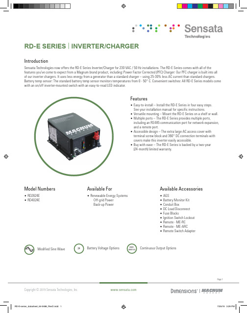
Model Numbers • RD2624E• RD4024EAvailable For• Renewable Energy SystemsOff-grid PowerBack-up Power24Battery Voltage OptionsModified Sine WaveSPECIFICATIONSRD2624E RD4024E INVERTER SPECIFICATIONSInput battery voltage range18 - 32 VDC18 - 32 VDCNominal AC output voltage230 VAC ± 5%230 VAC ± 5%Output frequency and accuracy50 Hz ± 0.4 Hz50 Hz ± 0.4 Hz1 msec surge current (amps AC)85100100 msec surge current (amps AC)22405 sec surge power (real watts)4700750030 sec surge power (real watts)410067505 min surge power (real watts)3350600030 min surge power (real watts)27005500Continuous power output at 25° C2600 VA4000 VAMaximum continuous input current172 ADC267 ADCInverter efficiency (peak)91%89%Transfer time30 ms20 msSearch mode (typical)< 7 watts< 8 wattsNo load (230 VAC output, typical)22 watts32 wattsWaveform Modified Sine Wave Modified Sine Wave CHARGER SPECIFICATIONSContinuous output at 25° C75 A105 ACharger efficiency (peak)87%85%Power factor> 0.95> 0.95Input current at rated output (AC amps)11.516GENERAL FEATURES AND CAPABILITIESTransfer relay capability30 AACFive stage charging capability Bulk, Absorb, Float, Equalize (requires remote), and Battery Saver™Battery temperature compensation Yes, 15 ft Battery Temp Sensor standardInternal cooling0 to 120 cfm variable speedOvercurrent protection Yes, with two overlapping circuitsOvertemperature protection Yes on transformer, MOSFETS, and batteryCorrosion protection Yes, PCB’s conformal coated, powder coated chassis/top, and stainless steel fasteners Output circuit breaker NAInput circuit breaker30 AACListings NoneWarranty Two yearsPage 2CONTACT US651-653-7000800-553-6418InverterInfo@Power ConversionPage 3Sensata Technologies, Inc. (“Sensata”) data sheets are solely intended to assist designers (“Buyers”) who are developing systems that incorporate Sensata products (also referred to herein as “components”). Buyer understands and agrees that Buyer remains responsible for using its independent analysis, evaluation and judgment in designing Buyer’s systems and products. Sensata data sheets have been created using standard laboratory conditions and engineering practices. Sensata has not conducted any testing other than that specifically described in the published documentation for a particular data sheet. Sensata may make corrections, enhancements, improvements and other changes to its data sheets or components without notice.Buyers are authorized to use Sensata data sheets with the Sensata component(s) identified in each particular data sheet. HOWEVER, NO OTHER LICENSE, EXPRESS OR IMPLIED, BY ESTOPPEL OR OTHERWISE TO ANY OTHER SENSATA INTELLECTUAL PROPERTY RIGHT, AND NO LICENSE TO ANY THIRD PARTY TECHNOLOGY OR INTELLECTUAL PROPERTY RIGHT, IS GRANTED HEREIN. SENSATA DATA SHEETS ARE PROVIDED “AS IS”. SENSATA MAKES NO WARRANTIES OR REPRESENTATIONS WITH REGARD TO THE DATA SHEETS OR USE OF THE DATA SHEETS, EXPRESS, IMPLIED OR STATUTORY, INCLUDING ACCURACY OR COMPLETENESS. SENSATA DISCLAIMS ANY WARRANTY OF TITLE AND ANY IMPLIED WARRANTIES OF MERCHANTABILITY, FITNESS FOR A PARTICULAR PURPOSE, QUIET ENJOYMENT, QUIET POSSESSION, AND NON-INFRINGEMENT OF ANY THIRD PARTY INTELLECTUAL PROPERTY RIGHTS WITH REGARD TO SENSATA DATA SHEETS OR USE THEREOF.All products are sold subject to Sensata’s terms and conditions of sale supplied at SENSATA ASSUMES NO LIABILITY FOR APPLICATIONS ASSISTANCE OR THE DESIGN OF BUYERS’ PRODUCTS. BUYER ACKNOWLEDGES AND AGREES THAT IT IS SOLELY RESPONSIBLE FOR COMPLIANCE WITH ALL LEGAL, REGULATORY AND SAFETY-RELATED REQUIREMENTS CONCERNING ITS PRODUCTS, AND ANY USE OF SENSATA COMPONENTS IN ITS APPLICATIONS, NOTWITHSTANDING ANY APPLICATIONS-RELATED INFORMATION OR SUPPORT THAT MAY BE PROVIDED BY SENSATA.Mailing Address: Sensata Technologies, Inc., 529 Pleasant Street, Attleboro, MA 02703, USA.ENVIRONMENTAL SPECIFICATIONS Temperature (Operating/Non-operating)-20° C to +60° C (-4° F to 140° F) to -40° C to +70° C (-40° F to 158° F)Operating humidity 0 to 95% RH non-condensingPHYSICAL SPECIFICATIONS Dimensions (h x w x d)13.75” x 12.65” x 8.0” (34.9 x 32.1 x 20.3 cm)Mounting Shelf (top or bottom up) or wallWeight 42 lb (19 kg)55 lb (25 kg)Shipping weight 47 lb (21.3 kg)60 lb (27.2 kg)Max operating altitude15,000’ (4570 m)Testing for specifications at 25° C.Specifications subject to change without notice.GENERAL NOTES。
AIMS Power PWRINV400W直流至交流电源逆变器使用说明书
DC TO AC POWER INVERTERPWRINV400W INSTRUCTION MANUALSAVE THIS MANUALYou will need the manual for the safety warnings and precautions, assembly instructions, operating and maintenance procedures, parts list and diagram. Keep your invoice with this manual. Write the invoice number on the inside of the front cover. Keep the manual and invoice in a safe and dry place for future reference.Basic Operation•Make sure that you choose the right operating voltage for both input and output of the inverter.•When unpacking, make sure that the inverter is in good condition. If any parts are missing or broken, please call AIMS Power, Inc. at the number found on the warranty card.•Place the power inverter on a flat surface. Make sure it has adequate ventilation and is not in direct sunlight. Fasten the inverter securely to the surface, using screws or some othermeans. If holes are to be drilled, follow safe, proper installation techniques.•Before you connect the battery cables, make sure the power switch is in the off position.Connect Red (+) battery cable to Red (+) inverter terminal. Connect Black (-) battery cable to Black (-) inverter terminal. Connect Red (+) battery cable to Red (+) battery terminal. Connect Black (-) battery cable to Black (-) battery terminal. Alligator clamp cables may be used but only to connect to the battery. Do not use clamps on inverter terminals. Alligator clamps are not a permanent solution. You may see a spark during connection.•Connect the ground cable to an earth ground, such as a metal water pipe or to the vehicle ground when used in a vehicle if the inverter includes a ground port.•Turn the power switch to the on position, which is located on the front of the inverter. The green LED light will confirm that AC power is present.•Before plugging the equipment into the inverter, make sure the equipment AND the inverter are off. Turn inverter on first, then turn on the equipment.•The power inverter can be used either while the engine is running or off.Warnings•Unplug the inverter when it is not in use.•If the AC inverter makes a beeping sound, turn off the equipment, unpl ug the inverter and restart the vehicle’s engine. The beeping sound is simply the low-battery warning, which indicates that the voltage of your battery is getting low. If you do not re-start your engine and continue operating the inverter, the inverter will automatically shut off, leavingyour vehicle's battery at about 10. 5 VDC. This will allow you to start your engine and resumeoperation of the inverter. It also reduces the fear of being stranded with a dead battery(dependent on health of battery).•This device should only be serviced by a qualified technician. This item does not have any serviceable parts.•Prevent body contact with grounded surfaces such as pipes, radiators, ranges, and refrigerator enclosures during installation.•Do not operate the inverter if under the influence of alcohol or drugs. Read warning labels on prescriptions to determine if your judgement or reflexes are impaired while taking drugs. Ifthere is any doubt, do not operate the inverter.•People with pacemakers should consult their physician(s) before using this product.Electromagnetic fields in close proximity to a heart pacemaker could cause interference to or failure of the pacemaker.•Keep children away. Children must never be allowed in the work area. Do not let them handle machines, tools, or extension cords.•Store idle equipment. When not in use, inverter must be stored in a dry location to prevent rust. Always lock up tools and the inverter and keep out of reach of children.•Size the inverter properly. Size the inverter for the surge rating of your equipment. The inverter’s continuous rating should be MORE than the surge rating of your equipment.Example: Power tool runs at 1500 watts but surges at 2500 watts. You should use an inverter >3000 watts.•Keep the inverter well-ventilated. Do not place any objects on top of or next to the inverter or allow anything to cover the cooling fans; doing so can cause the inverter to overheat,causing a potential fire hazard and/or damage to the inverter. Leave adequate ventilationspace underneath the inverter as well; thick carpets or rugs can obstruct air flow, causing the inverter to overheat.•Avoid unintentional starting. Be sure the switch is in the OFF position when not in use and before plugging in any appliance.Note: Performance of this unit may vary depending on the available battery power or appliance wattage.Warning: The warnings, cautions, and instructions discussed in this instruction manual cannot cover all possible conditions and situations that may occur. It must be understood by the operator that common sense and caution are factors which cannot be built into this product, but must be supplied by operator. Guard against electric shock. Do not open the metal case; risk of electric shock.Battery Use•To avoid over-discharging your vehicle battery, we recommend running your engine for 10-20 minutes to recharge the vehicle's battery if battery voltage drops <11V.•To properly size your battery, use the following formula: Volts * Amps = Watts or Watts/Volts = Amps. Example: 1000 watt inverter / 12 volts DC = 83.3 DC amps. In this example, you willneed 83.3 amps to power a 1000 watt load for 1 hour. If you need to power 1000 watts for 2hours you will need 83.3 * 2 = 166.66 DC amps available. A 100 amp hour battery will giveyou 100 amps / 166.66 = .6 hours so you will need two batteries if using 100 amp battery.This is if you fully deplete your batteries. We do NOT recommend fully depleting yourbatteries. This is just an example. Your power requirements may be different.•If you choose to use a female 12 Volt DC adapter for your inverter or to the inverter make sure wire size is correct.•IF YOU CONNECT THE WIRES TO THE INCORRECT TERMINALS, YOU WILL REVERSE THE POLARITY AND DAMAGE THE INVERTER.•REVERSED POLAR ITY WILL INSTANTLY VOID THE WARRANTY OF YOUR INVERTER, SO BE CAREFUL TO CONNECT YOUR INPUT WIRES PROPEPLY.•If you choose to operate a battery charger to replenish your battery’s voltage, be sure to check with charger manufacture before damaging the charger.•CONNECTING THE INVERTER’S DC INPUT TO A BATTERY CHARGER WILL VOID THE WARRANTY, AND MAY DAMAGE THE INVERTER.•Make sure that the battery voltage does not exceed 15 volts DC.•CONNECTING THE INVERTER TO A DC POWER SOURCE GREATER THAN 15 VDC WILL VOID THE WARRANTY, AND MAY DAMAGE THE INVERTER.CablesWe recommend that you refrain from using battery cables longer than 12 feet between the DC power source and the DC input of the inverter. Longer battery cables on the DC input will create a voltage drop which results in a reduction of efficiency and output. If you require more than 12 feet, use a bigger cable. We recommend using an extension cord between the AC output and AC appliance. You may use up to 100ft, high quality extension cord. A longer cord may result in reduced output. See Specifications chart for recommended battery cable size.Remote On/Off SwitchSome models include a remote port. An AIMS remote on/off switch may be connected to the remote port. The optional remote on/off switch is a convenientoption to turn the inverter on/off if the inverter is installed in a hard to reach area. Make sure the inverter is turned off before installing the remote switch. Plug the switch into the remote jack and then turn the main switch to the OFF position for the remote to work properly.Measuring The AC VoltageThe output waveform of the inverter is a MODIFIED SINE WAVE. If you choose to measure the AC output voltage, you must use a TRUE RMS MULTI METER. Using any other type of voltage measuring device will result in an AC voltage reading of 10 to 30 volts lower than actual voltage. When using a true RMS multi meter, you will get an accurate reading.SAFETY PRECAUTIONS•Do not open the case of the inverter. The high voltage inside the unit is the same type of power as your electrical outlets at home.•Do not let the cord of the inverter, or any appliance cord get wet. If you are operating the inverter in a moving vehicle, we recommend that you secure the inverter to prevent it fromshifting around while the vehicle is moving.•Do not operate this inverter in or around water. Water can damage the inverter, and water damage is not covered under warranty. Also, do not operate the inverter with wet hands. The AC voltage of the unit makes it an electrical shock hazard if operated with wet hands.•Allow at least 12 inches of clearance around the Inverter for air flow. Ensure the ventilation openings on the rear and bottom of the unit are not obstructed.•Do not connect the inverter directly to another AC power source. Damage may result, and such damage will void the inverter warranty.•Know the wattage requirements of your appliance. Use only those appliances which are limited by the capacity of this unit.•Use common sense. This device produces power just like your wall outlets at home and should be treated seriously. Keep it away from children.•Reversed polarity of AC power outlet LINE /NEUTRAL will void the warranty.•If there is anything wrong with the inverter, disconnect all of the power and contact technical support.If the Inverter does not appear to be functioning properly, check the following possible causes:•Poor contact: Clean contact parts thoroughly.•If the low battery alarm sounds, this means the input voltage is too low and battery needs to be recharged.•If you are getting a low output voltage, try reducing the load to minimize watts. You may have overloaded the inverter. Reduce your load. Also, keep input voltage above 10.5 volts tomaintain a constant flow of power.•If you are not getting any power output, turn the power switch Off and On again, until the green power light comes on. Your devices may draw too much power to operate them. Theinverter may be in thermal shutdown. Let it cool down and make sure there is adequateventilation around the unit.•If the green light turns red one of the following has happened:A.input voltage is too lowB.input voltage is too highC.short circuitD.inverter is close to overload•Battery voltage is too low: Start the engine to recharge the battery. Replace or recharge battery if needed.•Shuts down on overload: Reduce the wattage of your load.•Thermal shutdown: Under heavy loads for extended period, the inverter will shut down to prevent damage from excess heat. Simply reduce your load and allow theInverter to cool down.•Low-battery shutdown: Recharge your battery and resume operation.Very little maintenance is required to keep your inverter operating properly. You should disconnect input power first and then clean the exterior of the unit periodically with a dry cloth to prevent accumulation of dust and dirt. At the same time, tighten the screws on the DC input terminals.PLEASE READ THE FOLLOWING CAREFULLYNeither the manufacturer nor distributor makes any representation or warranty of any kind to the buyer that he or she is qualified to make any repairs to the product or that he or she is qualified to replace any parts of the product. In fact, the manufacturer and/or distributor expressly states that allrepairs and parts replacements should be undertaken by certified and licensed technicians and not by the buyer. The buyer assumes all risk and liability arising out of his or her repairs to the original product or replacement parts thereto, or arising out of his or her installation of replacement parts thereto.WARRANTYAIMS Corp., Inc. dba AIMS Power Warranty Instructions:This product is designed using the most modern digital technology and under very strict quality control and testing guidelines. If, however, you feel this product is not performing as it should, please contact us:**************************(775)359-6703We will do our best to resolve your concerns. If the product needs repair or replacement, make sure to keep your receipt/invoice, as that will need to be sent back along with the package and RMA# prepaid to AIMS. You have a full 1 year warranty from date of purchase.This warranty is valid worldwide with the exception that freight and duty charges incurred outside the contiguous 48 United States will be prepaid by customer.Except as provided above, AIMS makes no warranty of any kind, express or implied, including without limitation the implied warranties of merchantability and fitness for a particular purpose. In no event shall AIMS be liable for indirect, special or consequential damages. This warranty only applies to AIMS Power branded products. All other name brand products are warranted by and according to their respective manufacturer. Please do not attempt to return non-AIMS Power branded products to AIMS Power.For additional products such as:-Modified sine wave inverters-Pure sine wave inverters-Low Frequency Inverters-Solar Charge Controllers-Micro Grid Tied Inverters-Inverter Chargers and Automatic transfer switches-Converters DC-DC-Custom cut cables-Batteries-Solar Panels & RacksPlease visit our web site: Tofindoutwheretobuyanyofourproducts,youmayalsoe-mail:************************ (775)359-6703.。
AIMS Power 10,000瓦直流到交流电源逆变器 (V 2.0) 使用说明书
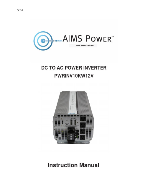
DC TO AC POWER INVERTER PWRINV10KW12VInstruction ManualIntroductionThe AIMS Power 10,000 watt inverter is the most technology advanced mobile DC to AC power inverter available. AIMS also offers the 8,000 Watt 12V or 12,000 Watt 24V.This inverter is used in a wide range of applications including back up power for remotehomes, off-grid systems, RVs, boats, commercial vehicles and mobile businesses. The10,000 watt inverter will operate most pumps, motors, lights, heaters, compressorbased appliances and hand tools.To get the most out of the power inverter, it must be installed and used properly. Readthe instructions in this manual before installing and using this product. Follow all safetyprecautions.FUNCTIONSFRONT VIEWA. On/Off switch: Leave in the OFF position during installation.B. Over temperature indicator: Lights when inverter protects itself against overheating. Invertershuts down while indicator is on. Inverter will restart automatically and indicator will turn off when the inverter cools.C. Over load indicator: Lights when inverter shuts down because of overload. Indicator will turn offand inverter will restart when overload is removed.D. Bar meters: Displays battery voltage and current. Current should be in the green zone forcontinuous operation. The inverter will operate for several minutes when the current is in the yellow zone. Operation with battery voltage or current in the red zone of a meter will result in protective shutdown of inverter.E. AC outlets: Maximum recommended output per outlet is 1500W.F. Remote port: Used with remote switch to turn inverter ON/OFF (sold separately).G. AC terminal block: Hard wire block providing inverter's full power.E: AC outletsD: Bar metersB: Over temperature indicatorA: On/Off switch C: Over load indicatorG: AC terminal Block F: Remote portREAR VIEWA: Fan: Do not obstruct, allow at least 12 inches for air flow.B: Battery terminals: Connect to 12V, or 24V, or 36V, or 48V (depending on inverter model) battery(s) or other DC power source. "+" is positive & " - " is negative. Reverse polarity connection will blow internal fuse and may damage inverter permanently. Make sure you check your input voltage and do not REVERSE POLARITY! This will void the warranty.C: Chassis ground lug: Connect to earth ground or to vehicle chassis using #8 AWG wire. Warning! Operation of the inverter without a proper ground connection may result in an electrical safety hazard.QUICK HOOK-UP AND TESTINGIf you would like to quickly hook-up the power inverter and check its performance before moving forward with your installation, please follow these guidelines:1. Unpack and inspect the power inverter, check to see that the power switch is in the OFF position.2. Before you connect the battery cables, make sure the power switch is in the off position. Connect Red (+) battery cable to Red (+) inverter terminal. Connect Black (-) battery cable to Black (-) inverter terminal. Connect Red (+) battery cable to Red (+) battery terminal. Connect Black (-) battery cable to Black (-) battery terminal. Alligator clamp cables may be used but only to connect to the battery. Do not use clamps on inverter terminals. Alligator clamps are not a permanent solution. You may see a spark during connection. Do not reverse the polarity. This may damage the inverter and void warranty. Caution! Loosely tightened connectors result in excessive voltage drop and may cause overheated wires and melted insulation. Reverse polarity connection will blow a fuse in inverter and may permanently damage the inverter. Damage caused by reverse polarity connection is not covered by our warranty. Warning! You may observe a spark when you make this connection since current may flow to charge capacitors in the power inverter. Do not make this connection in the presence of flammable fumes, as explosion or fire may result.A: FanB: Battery terminal (+)B: Battery terminal (-)C: Chassis grounding3. Set the power switch to the on position. Check the meters and indicators on the front panelof the inverter. The voltage bar graph should indicate 11 to 14 volts depending on the voltageof the power source. If it does not, check your power source and the connections to inverter.The other indicators should be off.4. Set power inverter switch to the OFF position, the indicator l ights may blink and theinternal alarm may sound momentarily. This is normal. Plug the test load into the ACreceptacle on the front panel of the inverter. Leave the test load switch off.5. Set power inverter switch to the ON position and turn the test load on, the inverter shouldsupply power to the load. If you plan to measure the true output R.M.S. voltage of inverter, ameter such as FLUKE 87A, BACKMAN 4410 or TRIPLETT 4200 must be used.INSTALLATION1. Where to installThe power inverter should be installed in a location that meets the following requirements:a. Dry - Do not allow water to drip or splash onto the inverter.b. Cool - Ambient air temperature should be between 0°C and 40°C, the cooler the better when operating in this rangec. Ventilation - Allow at least one inch of clearance around the inverter for air flow. Ensure the ventilation openings on the rear and bottom of the unit are not obstructed.d. Safety - Do not install the inverter in the same compartment as batteries or in any compartment capable of storing flammable liquids such as gasoline.2. CablesDC to AC inverters require high amperage/low voltage DC power to low amperage/high voltage AC power. To operate properly, connect inverter DC input terminals direct to battery with heaviest wire available see below:12 Volt Model: 2x set of 4/0 AWG (2 red + 2 black) and quantity 2- ANL500KIT-500 Amp fuse kits for positive (red) cablesBattery Cables InstallationWhen connecting the AC inverter to the battery terminals, it is important to connect the "+" wire to the "+" terminal and the wire to the "-" wire to the “-“ terminal. Do NOT reverse the polarity. It will void the warranty. Make sure you connect negative to negative and positive to positive.Red (+) * 2Black (-) * 2REDBLACKCaution!DO NOT allow the wires to cross or touch each other. Install the cables facing away from each other and screw tightly. When connecting the battery cables to the terminals of the inverter, make sure they do not touch the case.3. GroundingThe power inverter has a lug on the rear panel marked "chassis ground" This is to connect the chassis of the power inverter to the ground.The ground terminals in the AC outlets on the front panel of the inverter are also connected to the ground lug.The chassis ground lug must be connected to a grounding point, which will vary depending on where the power inverter is installed. In a vehicle, connect the chassis ground to the chassis of the vehicle. In a boat, connect to the boat's grounding systems in a fixed location, connect the chassis ground lug to an earth point, which will vary depending on where the power inverter is installed.The neutral (common)conductor of the power inverter AC output circuit is connected to the chassis ground. Therefore, when the chassis is connected to ground, the neutral conductor will also be grounded.This conforms to national electrical code requirements that separately derived AC sources (such as inverters and generators) have their neutral tied to ground in the same way that the neutral conductor from the utility line is tied to ground at the AC breaker panel.Caution! The Negative DC input of the power inverter is connected to the chassis. DO not install the power inverter in a positive ground DC system. A positive ground DC system has the positive terminal of the battery connected to the chassis of the vehicle or to the grounding point.Warning! Do not operate the power inverter without connecting it to ground. Electrical shock hazard may result.OPERATIONTo operate the power inverter, turn it on using the ON/OFF switch on the front panel. The power inverter is now ready to deliver AC power to your loads. If you are operating several loads from the power inverter, turn on separately after the inverter has been turned on. This will ensure that the power inverter does not deliver starting currents to all of the loads at once.1. Controls and indicatorsThe ON/OFF switch turns the control circuit in the power inverter on and off. It does not disconnect power from the power inverter.When the switch is in the OFF position, the power inverter draws no current from battery. When the switch is in the ON position but with no load, the power inverter draws less than 450 mA.2. Battery voltage indicatorThe battery voltage bar graph indicates the voltage at the input terminals of the power inverter. At low input current, this voltage is very close to the battery voltage. At high input current, this voltage will be lower than the battery voltage because of the voltage drop across the cable and connections.Ideally, the voltage should remain in the green area of the bar graph. If the voltage goes into the red area at top or bottom of the graph, inverter may shut-down.3. Battery current indicatorThe battery current bar graph indicates the current drawn from the battery by the power inverter, it will not indicate current by other loads also connected to the battery. The indicator only displays DC volts and amps.For long term operation, the current should be in the green area of the bar graph. Short term operation is possible with current in the orange area. If the current rises to the red area, the inverter will reduce its output voltage to protect itself.To measure AC current, use a TRUE RMS MULTI METER.4. Over temp indicatorThe over temp indicator indicates that the power inverter has shut itself down because it has become overheated. The power inverter may overheat because it has been operated at power levels above its rating, or because it has been installed in a location which does not allow it to dissipate heat properly.5. Over load indicatorThe over load indicator indicates that the power inverter has shut itself down because its output circuit has been short circuited or drastically overloaded. Switch the ON/OFF to OFF, correct the fault condition, and then switch the ON/OFF back to ON.THINGS TO CONSIDER REGARDING THE LOADThe 10,000W inverter will operate most AC loads within its power rating. When determining whether a microwave oven can be operated by the 10,000W inverter, remember that the power commonly advertised for microwave ovens is the cooking power (the power delivered to the food) not the power actually consumed by the microwave oven. The microwave oven will consume 40% to 100% more than its advertised cooking power. Check the rating sticker on the back of the oven to determine its actual power draw. The 10,000W inverter will operate small microwave ovens (0.2 to 0.3 cubic foot capacity) that draw is about 1700 watts.Some induction motors used in refrigerators, freezers, pumps, and other motor operated equipment require very high surge currents to start. The power inverter may not be able to start some of these appliances even though their rated current draw is within the rating of the power inverter.If a motor refuses to start, observe the battery voltage indicator while trying to start the motor. If the battery voltage indicator drops below 10.5V DC while inverter is attempting to start the motor, this may be why the motor won't start.Make sure that the battery connections are good and that the battery is fully charged. If the connections are good and the battery to is charged, but the voltage still drops below 11 volts, you may need a larger battery or larger battery bank.(*2 for 24V *3 for 36V *4 for 48V)INPUT VOLTAGEThe power inverter will operate from input voltage ranging from 10V-16V. If the voltage drops below input range, an audible low battery warning will sound and the voltage indicator will be in the lower red zone. The power inverter will shut down if the input voltage drops below 10V +/- .5V. This protects your battery from being over discharged.The power inverter will also shut down if the input voltage exceeds 17V +\-.5V. This protects the inverter against excessive input voltage.The voltage indicator will be in the upper red zone. Although the power inverter incorporates protection against over voltage, the inverter is at risk of permanent damage if the input voltage is allowed to exceed 17V +\-.5V.TROUBLESHOOTINGmon problemsa. Buzz in audio systems:Some inexpensive stereo systems and radios will emit a buzzing noise from their loudspeakers when operated from the power inverter. This is because the power supply in the device does not adequately filter the modified sine wave produced by the power inverter. The only solution is to use a sound system that incorporates a higher quality power supply.b. Television interference:Operation of the power inverter can interfere with television reception on some channels. If this situation occurs, the following steps may help to alleviate the problem.-Make sure that the chassis ground lug on the back of the power inverter is solidly connected to the ground system of your vehicle, boat or home.-Do not operate high power loads with the power inverter while watching television.-Move the television as far away from the power inverter as possible.-Keep the cables between the battery and the power inverter as short as possible and twist them together with about 2 to 3 twists per foot. This minimizes radiated interference from the cables.SPECIFICATIONSAIMS Corp., Inc. dba AIMS Power Warranty Instructions:This product is designed using the most modern digital technology and under very strict quality control and testing guidelines. If, however you feel this product is not performing as it should, please contact us:**************************(775)359-6703We will do our best to resolve your concerns. If the product needs repair or replacement, make sure to keep your receipt/invoice, as that will need to be sent back along with the package and RMA# prepaid to AIMS. You have a full 1 year warranty from date of purchase.This warranty is valid worldwide with the exception that freight and duty charges incurred outside the contiguous 48 United States will be prepaid by customer.Except as provided above, AIMS Power makes no warranty of any kind, express or implied, including without limitation the implied warranties of merchantability and fitness for a particular purpose. In no event shall AIMS be liable for indirect, special or consequential damages. This warranty only applies to AIMS Power branded products. All other name brand products are warranted by and according to their respective manufacturer. Please do not attempt to return non-AIMS Power branded products to AIMS Power.For additional products such as:-Modified sine wave inverters-Pure sine wave inverters-Low Frequency Inverters-Solar Charge Controllers-Micro Grid Tied Inverters-Inverter Chargers and Automatic transfer switches-Converters DC-DC-Custom cut cables-Batteries-Solar Panels & RacksPlease visit our web site: Tofindoutwheretobuyanyofourproducts,youmayalsoe-mail:************************ (775)359-6703.。
逆变器使用说明书
车载逆变器用户手册1、简介感谢您购买HUASYN系列的逆变器。
为了您能舒适、安全的使用本产品,请仔细阅读本说明书,说明书中包含关于本产品的重要信息,请保留此说明书以供以后参考。
HUASYN系列逆变器拥有您所期待的的卓越品质,无论你接在汽车点烟器插孔,还是接在电瓶上,都能直接转换为交流电。
它可广泛用于各类家用电器上,让您在商务工作、驾车旅游、停电应急的时候,给您源源不断的动力。
2、产品特性采用专用智能IC控制逆变器产品,具有非常完善的保护功能和指示功能。
采用优质的双面线路板及电子元件,保证产品的高质量,高性能。
转换效率高、小巧轻便、适用范围广的特点。
产品示意图:75W100W150W200W300W500W3、使用说明a:使用环境基于安全和性能的考虑,HUASYN系列产品应该在以下环境下使用:干燥:不能浸水或淋雨阴凉:环境温度应该在0℃到40℃之间通风:保持壳体上方5CM内无异物,其它端面通风良好,确认风扇不会在工作过程中不会发生阻塞或障碍(适用于有带风扇的产品),以便防止出现通风不良的情况。
b:操作方法1、确定所使用的电器功率应小于所使用的逆变器的额定输出功率。
2、当使用设备输出功率小于200W时,将逆变器开关置于关闭位置,然后雪茄头紧密地插入车内点烟器插口,确保雪茄头良好接触。
3、当使用设备输出功率大于200W时,必须通过鳄鱼夹线使用,引线的太阳端子接至逆变器接线柱,颜色应该匹配,引线端为红色的接逆变器上的红色接线柱,引线端为黑色的接逆变器的黑色接线柱;另外一端的鳄鱼夹连接所使用过的电瓶,红色鳄鱼夹接“+”级,黑色鳄鱼夹接“﹣”级)。
4、输入端接好后,打开开关,逆变器指示灯将发亮,表示已经有交流电输出,逆变器便可以开始正常工作。
5、将需要使用的电器插入的逆变器的输出端AC插座或USB接口充电,根据你所使用的设备选择。
6、开启你的电器开关,HUASYN逆变器便可以给你带来源源不断的交流电能。
4、产品规格HUASYN系列逆变器型号电气特性输入电压12V 24V 输出电压220V 110V 输出频率50Hz 60Hz 额定功率峰值功率使用温度输出波形改良型正弦波转换效率保护功能物理特征尺寸(mm)重量(g)(产品参数标准如有变动,以本公司为准,怒不另行通知)5、保护功能本系列逆变器具有多重保护功能,能够给你带来更多保障。
Panasonic SM-E265Q 迷你逆变器系列产品说明书

Pursuing the Ideal Compact InverterSeries Designed for excellent performance and user friendlinessOFFONMotor CurrentDC VoltageOutput FrequencyDC VoltageOutput FrequencyMotor CurrentM : 1-phase 100V classS : 1-phase 200V class L : 3-phase 200V class H: 3-phase 400V class(Example of WJ200-055LF)• Frequency commanded by the inverter: 0.5Hz.OFFONMotor CurrentOutput FrequencyMotor CurrentOutput FrequencyTripPursuing the Ideal Compact InverterDesigned for excellent performance and user friendliness Conformity to global standardsSink / source logic is standardWide input power voltage rangePMWJ200IMIM + InverterEC97J1095Features P2–5Standard Specifications P6General Specifications P7Dimensions P8Operation and Programming P9Terminal (Arrangements/Functions)P10–11Function List P12–20Protective Functions P21Connecting Diagram P22–23Connecting to PLC P24Wiring and Accessories P25For Correct Operation P26–27IndexSafety terminal E=625V cable:100mInverter WJ200One network expansion card canbe installed inside the WJ200.Easy adjustment of frequency*1: The applicable motor refers to Hitachi standard 3-phase motor (4p). When using other motors, care must be taken to prevent the rated motor current (50/60Hz) from exceeding the rated output current of the inverter.*2: The output voltage varies as the main supply voltage varies (except when using the AVR function). In any case, the output voltage cannot exceed the input power supply voltage.3-phase 200V class3-phase 400V class(only with CT)*3: The protection method conforms to JEM 1030.*4: To operate the motor beyond 50/60Hz, consult the motor manufacturer for the maximum allowable rotation speed.*5: The braking torque via capacitive feedback is the average deceleration torque at the shortest deceleration (stopping from 50/60Hz as indicated). It is not continuous regenerative braking torque. The average deceleration torque varies with motor loss. This value decreases when operating beyond 50Hz. If a large regenerative torque is required, the optional regenerative braking unit and a resistor should be used.*6: 1-phase 100V class is only with CT.*7: The frequency command is the maximum frequency at 9.8V for input voltage 0 to 10VDC, or at 19.6mA for input current 4 to 20mA. If this characteristic is not satisfactory for your application, contact your Hitachi representative.*8: The storage temperature refers to the short-term temperature during transportation.*9: Conforms to the test method specified in JIS C0040 (1999). For the model types excluded in the standard specifications, contact your Hitachi sales representative.WJ200 Series can be easily operated with the digital operator provided as standard. Operation PanelKeypad Navigation MapSingle-Digit Edit ModeIf a target function code or data is far from current position, using the single-digit edit mode makes it quicker to navigate there. Pressing the up key and down key at the same time brings you into the digit-by-digit navigation mode.Terminal Arrangement and Screw DiameterTerminal Arrangement of Control Circuit TerminalsWiring sample of control logic terminal (Sink logic)Sink logicSource logicSink /source logic of intelligent input terminalsSink or source logic is switched by a short bar as below.Terminal FunctionsIf a desired parameter is not displayed, check the setting of function "b037"(function code display restriction). To display all parameters, specify "00" for "b037".[○=Allowed ×=Not parmitted][○=Allowed ×=Not parmitted][○=Allowed ×=Not parmitted][○=Allowed ×=Not parmitted][○=Allowed ×=Not parmitted]][○=Allowed ×=Not parmitted[○=Allowed ×=Not parmitted]*1: Reset operations acceptable 10 seconds after the trip.*2: The inverter will not accept any reset command after an EEPROM error (E08), CPU error (E11), Ground fault (E14) or Driver error (E30) occurs with error code displayed. Turn off the inverter power once. If error is displayed when the inverter power is turned on subsequently, the internal memory device may have failed or parameters may have not been stored correctly. In such cases, initialize the inverter, and then re-set the parameters.*3: Reset cannot be released with the STOP/RESET key. Please reset it with the inverter power or reset terminal (18:RS).How to access the details about the present faultSource Type LogicSink Type LogicConnection with Input TerminalsAttention when inverter plurals is usedApplication to Motors[Application to general-purpose motors]Notes on UseNotes on Peripheral Equipment SelectionHigh-frequency Noise and Leakage CurrentLifetime of Primary Parts。
逆变器操作说明及故障处理
一逆变器原理介绍1.1逆变(invertion):把直流电转变成交流电的过程。
逆变电路是把直流电逆变成交流电的电路。
当交流侧和电网连结时,为有源逆变电路。
变流电路的交流侧不与电网联接,而直接接到负载,即把直流电逆变为某一频率或可调频率的交流电供给负载,称为无源逆变。
逆变桥式回路把直流电压等价地转换成常用频率的交流电压。
逆变器主要由晶体管等开关元件构成,通过有规则地让开关元件重复开-关(ON-OFF),使直流输入变成交流输出。
当然,这样单纯地由开和关回路产生的逆变器输出波形并不实用。
一般需要采用高频脉宽调制(SPWM),使靠近正弦波两端的电压宽度变狭,正弦波中央的电压宽度变宽,并在半周期内始终让开关元件按一定频率朝一方向动作,这样形成一个脉冲波列(拟正弦波)。
然后让脉冲波通过简单的滤波器形成正弦波。
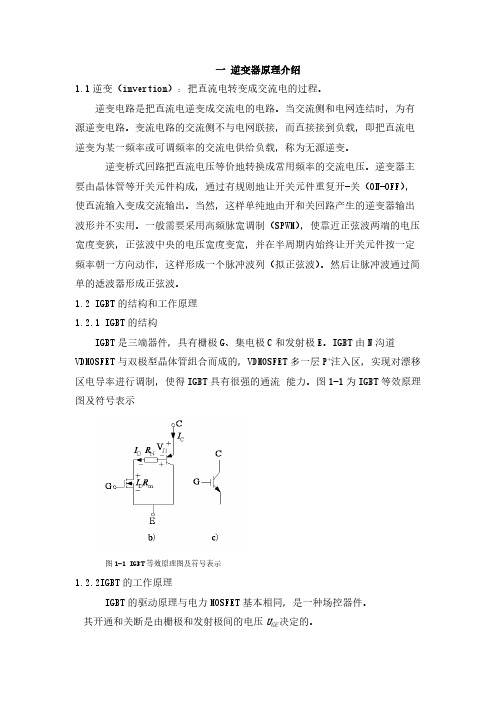
1.2 IGBT的结构和工作原理1.2.1 IGBT的结构IGBT是三端器件,具有栅极G、集电极C和发射极E。
IGBT由N沟道VDMOSFET与双极型晶体管组合而成的,VDMOSFET多一层P+注入区,实现对漂移区电导率进行调制,使得IGBT具有很强的通流能力。
图1-1为IGBT等效原理图及符号表示图1-1 IGBT等效原理图及符号表示1.2.2IGBT的工作原理IGBT的驱动原理与电力MOSFET基本相同,是一种场控器件。
其开通和关断是由栅极和发射极间的电压U GE决定的。
当U GE为正且大于开启电压U GE(th)时,MOSFET内形成沟道,并为晶体管提供基极电流进而使IGBT导通。
当栅极与发射极间施加反向电压或不加信号时,MOSFET内的沟道消失,晶体管的基极电流被切断,使得IGBT关断。
电导调制效应使得电阻R N减小,这样高耐压的IGBT也具有很小的通态压降。
1.3逆变电路介绍1.3.1逆变产生的条件为1,要有直流电动势,其极性须和晶闸管的导通方向一致,其值应大于变流器直流侧的平均电压。
2要求晶闸管的控制角α>π/2,使U d为负值。
Victron Energy SinusMax 三相交流逆变器产品介绍说明书

SinusMax - Superior engineeringDeveloped for professional duty, this range of inverters is suitable for the widest range of applications. The design criteria have been to produce a true sine wave inverter with optimised efficiency but without compromise in performance. Employing hybrid HF technology, the result is a top quality product with compact dimensions, light in weight and capable of supplying power, problem free, to any load.Extra start-up powerA unique feature of the SinusMax technology is very high start-up power. Conventional high frequency technology does not offer such extreme performance. These inverters, however, are well suited to power up difficult loads such as refrigeration compressors, electric motors and similar appliances.Virtually unlimited power thanks to parallel 3-phase and split phase operation capabilityUp to 6 units inverters can operate in parallel to achieve higher power output. Six 24/3000 units, for example, will provide 15 kW / 18 kVA output power. Operation in 3-phase or split phase configuration is also possible.To transfer the load to another AC source: the automatic transfer switchIf an automatic transfer switch is required we recommend using the MultiPlus inverter/charger instead. The switch is included in these products and the charger function of the MultiPlus can be disabled. Computers and other electronic equipment will continue to operate without disruption because the MultiPlus features a very short switchover time (less than 20 milliseconds).Communications interfaceThese larger inverter models come with a VE.Bus port. All you need to connect to your PC is our MK3-USB VE.Bus to USB interface (see under accessories). Together with our VictronConnect or VEConfigure software, which can be downloaded free of charge from our website, parameters of the inverters can be customized. This includes output voltage and frequency, over and under voltage settings and programming the relay. This relay can for example be used to signal several alarm conditions, or to start a generator. The inverters can also be connected to a GX device (eg Cerbo GX) for monitoring and control.New applications of high power invertersThe possibilities of paralleled high power inverters are truly amazing. For ideas, examples and battery capacity calculations please refer to our book ‘Energy Unlimited’ (available free of charge from Victron Energy and downloadable from ).Inverter 24/3000Battery ChargerInverterParallel,3-phase and split-phase operationYesInput voltage range (VDC) 9.5 – 17 V19 – 33 VOutputOutput voltage: 120 VAC ±2 % Frequency: 60 Hz ± 0,1 % (1)Cont. output power at 25 ºC / 77 ºF (VA) (2) 3000 3000 Cont. output power at 25 ºC / 77 ºF (W) 2400 2400 Cont. output power at 40 ºC / 104 ºF (W) 2200 2200 Cont. output power at 65 ºC / 150 ºF (W) 1700 1700 Peak power (W) 6000 6000 Max. efficiency (%) 93 94 Zero load power (W)20 20 Zero load power in AES mode (W) 15 15 Zero load power in Search mode (W) 810Programmable relay (3) Yes Protection (4)a - gVE.Bus communication port For parallel and three phase operation, remote monitoring and system integrationRemote on-offYesCommon CharacteristicsOperating temperature range: -40 to +65 ºC (-40 – 150 °F)Humidity (non-condensing): max 95%Common Characteristics Material & Colour: aluminium (blue RAL 5012) Protection category: IP 21Battery-connection 2+2 M8 bolts 120 VAC-connection Screw terminals Weight18 kg 38 lbsDimensions (hxwxd)362x258x218 mm 14.3x10.2x8.6 inchSafetyEN 60335-1 Emission ImmunityEN 55014-1 / EN 55014-21) Can be adjusted to 60 Hz and to 240 V 2) Non-linear load, crest factor 3:13) Programmable relay that can a.o. be set for general alarm, DC under voltage or genset start/stop function. AC rating: 120 V/4 ADC rating: 4 A up to 35 VDC, 1 A up to 60 VDC4) Protection key:a) output short circuit b) overloadc) battery voltage too high d) battery voltage too low e) temperature too highf) 120 VAC on inverter output g) input voltage ripple too highComputer controlled operation and monitoringSeveral interfaces are available:Inverter ControlThis panel can also be used on a MultiPlus inverter/charger when an automatic transfer switch but no charger function is desired. The brightness of the LEDs is automatically reduced during night time.BMV Battery MonitorThe BMV Battery Monitor features an advanced microprocessor control system combined with high resolution measuring systems for battery voltage and charge / discharge current. Besides this, the software includes complex calculation algorithms, like Peukert’s formula, to exactly determine the state of charge of the battery. The BMVselectively displays battery voltage, current, consumed Ah or time to go. The monitor also stores a host of data regarding performance and use of the battery.Several models available (see battery monitor documentation).Color Control GXProvides monitor and control. Locally, and also remotely on the VRM Portal.MK3-USB VE.Bus to USB interfaceConnects to a USB port (see ‘A guide to VEConfigure’)VE.Bus to NMEA 2000 interfaceConnects the device to a NMEA 2000 marine electronics network. See the NMEA 2000 & MFD integration guide。
- 1、下载文档前请自行甄别文档内容的完整性,平台不提供额外的编辑、内容补充、找答案等附加服务。
- 2、"仅部分预览"的文档,不可在线预览部分如存在完整性等问题,可反馈申请退款(可完整预览的文档不适用该条件!)。
- 3、如文档侵犯您的权益,请联系客服反馈,我们会尽快为您处理(人工客服工作时间:9:00-18:30)。
USER’S MANUALINVERTERPure sine-wave series Copyright2009-2012Product name…………………………………………Agent or dealer(stamp)Style NO.…………………………………………………Checker………………………………………TEL…………………………………………………………………Linkman………………………………………Series NO.………………………………………………ADD.………………………………………………………………TEL…………………………………………………Purchased date……………………………………Fax…………………………………………………6 Please strictly comply with the warnings and operation guides explained in this manual. And keep the book properly.Don’t operate this machine before reading all the safety instructions and operation guides. Otherwise, it will damage the devices or even cause safety accidents!Note:1.Connect the DC input cable for use make sure when you distinguish between being "+"negative "-" pole, as a direct re sult of inadvertent connection error will damage the inverter!2.W hen press the “on” bu tton, at the same time must be see the green light and hear the sound of relay, keep press “on” button about 3sec, until buzzer sound, stop to press “on” button, the inverter will be turn on.3.If didn’t follow steps 2 leading to not boot properly, please disconnect the battery cable, and then start button for about 10 seconds or continuous pre ss several times, and then reconnect the battery cable, at last follow 1 step to operation.Content1.Operation instructions (1)2.Feature (2)3.Scope (2)4.Installation instructions (2)5.Front panel directions……………………3-46.Specification (5)7.Free repair and maintenance………………6 6. Technical Specifications51. ON/OFF button2. output voltage3. load capacity4. load capacity5. frequency display (DC model)6. input voltage(AC model)7. LINE AC input light8. INV inverter light 9. FAULT fault light1. LCD display2. LINE AC input light3. INV inverter light4. CHA charging light5. FAULT fault light6. ON/OFF button7. CHK button4 1.Secure Operation PrecautionsWe have fully considered personal and state safety factors when designing the product. But improper operation may cause safety accident, so please comply the followings when using or installing for your safety and benefits:(1) When installing the inverter, professional operators are needed or connectwith the dealer.(2) Assure the electric power supply meets the standard.The battery DC voltage is the correct : the DC voltage input range is ±15% , the battery and the inverter input connector plus-minus polarity must be correctly.Special notice: this product uses single-phase 220V voltage. Please check whether the output connector is connected well. Please confirm the load power don’t be over the inverter power.(3) Don’t douse any liquid into the inverter or use wet cloth to wipe the cabinet.Never touch the AC output or input connector with wet hands.(4) Never make bold to replace the accumulator connection wire of the inverter,if needed, please contact the service department to confirm it.(5) Please don’t use the inverter in sloppy, dusty, high temperature ortemperature varies too sharply environment. Suggested environment temperature is 0℃~45℃. Please don’t jam the louver beside the machine or use the machine beside heat sources such as electric heater and radiator. Please avoid sunshine,dust and the dewing situation.(6) Don’t let self-determination deficient people (such as a child) use theproduct.(7) Make sure connect ground wire when connecting the machine with indoorelectric supply net, and the size of the input wires should meet the demand of indoor loads, or it will heat deal if the size of the wire is too small and may cause fire accident. Suggested the machine should be operated by professional technicians.12. Performance Specification of Intelligent inverter (1) The inverter is designed by our company independently; it’s controlled byCPU, high quality and modify sine wave intelligent inverter(2) Our product is used for the many kinds of the single phase equipments,example: motor, screw tools,tube light etc.family equipments, and also it can be used for the industry and communication equipments.(3) Single key intelligent switching, easy to operated(4) Output short circuit protection (when the inverter is working on batterymode): when there is short circuit, the inverter will indicate it and the machine will shut down automatically.(5) Overload protection: when there is overload, the machine will prompt youand protect the inverter from being damaged automatically. Over 100%-120%, inverter shuts down 30s later, over 150%, inverter shuts down at once.(6) Internal circuit can protect the battery .when the battery voltage is underthe 15% level,the inverter will be shut down at once.Warnning :A.If not allowed by our company, this device can’t supply power for the equipments which maintain the lifeB.This products is designed to supply the reserve inverted power for the home electric appliances, so it’s not fit for the precision equipmentsC.If it is used for the computer, the computer must have a enough power inside. Or the computer maybe is restarted, when the city power is interrupted.3. Use range of Intelligent inverterit can be used for t family equipments, and also the industry and communication equipments.4. Installation Guides for inverter(1) 1000W power output and the following connections using the form ofMulti-outlet, DC input lead straight out of the use of connected(2) 1000W power output over using the form of Multi-outlet and output terminalblock , DC input terminal station used to connect(3) Multi-outlet can load less than 10A220VAC equipments.25. Explanation about the indication and status of Panels3。