灵通6600中文说明书
对讲机操作感受及说明(灵通6100Plus、灵通6600、灵通6288)
对讲机操作感受及说明(灵通6100Plus、灵通6600、灵通6288)作者:BD2IAQLT-6100PLUS已经到手一些时间了。
现将一些使用情况与大家交流。
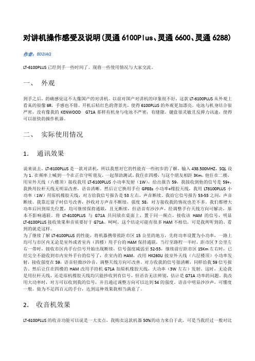
一、外观到手之后,的确感觉这不太像国产的对讲机。
以前对国产对讲机的印象很不好,这款LT-6100PLUS从外观上看真的很像6R,手感也不错。
开机后桔红色的背景光,使得6100PLUS的外观更加漂亮。
电池与机身结合很严密,没有像我的KENWOOD G71A那样有机身与电池不严密,有缝隙。
键盘很灵敏且反弹力讯速,使得可以很快的操作机器。
二、实际使用情况1.通讯效果说来说去,LT-6100PLUS是一款对讲机,所以我想对它的性能有一些初步的了解。
输入438.500MHZ,SQL设为1。
在频率上喊到一个在正在守听朋友,一起帮助测试。
我住在四楼,与这个朋友相距3Km,他住在二楼,用室外天线(六楼顶)接收我用LT-6100PLUS小功率发射(1W),给出报告59,我接收到他的信号是59+,我换用拉杆天线无明显改善,语音清晰。
然后让它换用手台GP88s小功率+橡胶天线,我用LT6100PLUS小功率(1W)用原机橡胶天线,对方给我信号报告是53左右,声音断续。
我给它信号报告53-55之间,声音断续。
我靠近窗子时信号改善,抄收对方声音不断续,强度58,对方接收我的情况也差不多。
我们都增大功率后回到原先位置,均可继续保持通联,且无断续,但语音有沙沙声,经调整手台天线方向可解决,基本不影响通联。
将LT-6100PLUS与G71A共同放在桌面上,置于同一频点,接收该HAM的信号,明显LT-6100PLUS接收效果和音质要好于G71A。
呵呵,这个结论可能有很多HAM不相信,可是我所听到的、看到的就是这样。
为了继续了解LT-6100PLUS的性能,将机器携带致距市区15公里的地方,先将功率设置为小功率,一路上均可与市区内无论是室外或者室内(四楼)用手台的HAM保持通联,当行至路程一半时,距市区7公里左右一带时,接收市区内手台信号开始出现断续,信号强度减弱至52-55,继续前行距市区15Km左右时,已经完全不能收到市内室外手台的信号了,在室内的HAM,改用HX260U接室外天线(六层楼顶)小功率发射,接收强度在59,语音轻微沙沙音,调整天线方向可改善。
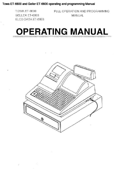
Towa ET-6600和Geller ET-6600操作与编程手册说明书
Setting the Terminal Number..............................................................................79
Setting the Machine Number ...............................................................................79
Character Code Table............... .........................................................13
2 Setting Up
2.1 Installing the Cash Register .......
.. ............................................................... 14
4.3 Function Programming at PI pOsition ..............................................................77
4.3.1 Setting the Basic Data..............................................................................................78
2.2 Initializing Your Cash Register .......................................................................... 14
6600的使用操作规程1

6系列仪器的操作指南一.安装.1.ECOW ATCH软件安装在电脑.2.按标准步骤,安装传感器.传感器的O型圈必须涂薄薄一层硅油,调整好传感器和主机底口的传感器的接口,轻轻用手插到位,仔细紧固传感器的螺丝.用手紧固到位.不要用工具紧固.3.若有光学传感器,先安装光学传感器,保留光学传感器的黑色橡胶帽,以免该传感器头因安装碰撞.4.DO传感器先安装DO膜,5775的组件内有白色瓶KCL请用蒸馏水稀释到该瓶的肩部,摇匀,静止15分钟,再取膜安装传感器.5.DO膜内应无气泡,无浊物,膜无皱纹.6.安装电池在电池仓(2号碱性电池,最好使用进口电池),特别注意,涂硅油作好防水.7.检查仪器的各附件,6095B,现场电缆(6091….或者6092,6093)先采用在线方式.8.带好保护套,校正杯(运输杯)内确保存有淡水.9.采样开始,卸去光学传感器的黑色保护橡胶套.10.上好保护套,注意不要损伤传感器.11.连接现场电缆到仪器,注意在仪器的连接端的金属内有一O型圈,必须涂硅油,拧好连接的丝.不必太用力.12.连接6095B到计算机的COM口.13.在COMM图标处,点击,出现设置.COMM 口设置,选择择安装的COMM口.14.通讯设置如下:BAUT RA TE:9600,BITS 8,STOP BITS 1, PARITY NONE15.打开ECOW ATCH的文件,双击带鞭图标,选择恰当COMM.确定OK.16.出现#17.输入MENU,回车18.进入主菜单19.输入1----RUN20.观察数据的稳定性,二.校正1.新装传感器必须校正.2.已再用仪器,从数据看是否需要校正传感器.如果传感器的数据符合要求.DO,PH,SPCOND,必须校正,3.浊度和叶绿素传感器看性能,转刷停位是否正常,(一) 电导1.电导传感器校正应选择恰当的标准电导液.注意电导单位.2.电导校正步骤.3.从主菜单-----进入CALIBERATE----CONDUCTIVITY4.选SP CONDUCTIVITY,回车5..选择恰当的电导液6.注意校正杯的清洁,电导液应淹没电导传感器的中间圆形口.7.输入准确的数值8.读数稳定后,按ENTER9..电导校正完毕.10退回主菜单(二).PH传感器PH传感器调试时和测试前,须校正.1.从主菜单-----选择CALIBERA TE----选择ISE PH2.出现三种选择1.---1.POINT,2---2.POINTS,3.---3POINTS3.选择2---2.POINTS4.清洁水(蒸馏水)清洗校正杯和传感器,以利于校正液的循环使用.5.装入校正杯PH7.0的缓冲液适当体积.6.按照屏幕提示输入第一点,温度下的PH值7.0 ±X,回车.(X是当前温度的PH值余数)7.待PH值稳定时,确认(回车)8.清洁水(蒸馏水)清洗校正杯和传感器.9.按回车,出现第二点值.输入第二点温度的PH值10.0±X. (X是当前温度的PH值余数)10.使用蒸馏水清洗校正杯及传感器11.倒入PH10的缓冲液12.按回车,出现第二点值.输入第二点温度的PH值10.0±X. (X是当前温度的PH值余数)13.待PH稳定,按确认(回车)14.使用ESC退到主菜单,(三) DO校正21.同上进入溶氧校正的程序,选择在不同测量方式下校正.连续性采样按35----40步骤进行.无人照料和长期监测时,请按42和43步骤设置完毕,再按35----40步骤校正22.MAINMENU――选择CALIBERATE―――――选择DISSOSIVEOXYGEN23.两个校正选项:1.DO%, 2. MG/L24.进入1.—DO%25.输入当地大气压(MMHG)26.校正杯内放少许水.仅拧一丝校正杯.27.等待15分钟.按确认.28.DO%显示近100%(或当前大气压下的饱和度)29.在线测量溶氧校正完毕.若采用无人照料方式工作,或连续检测,采用将在ADV ANCE菜单中将AUTO232击活,30.在SET UP将DO W ARM UP TIMES=60秒.(四) 浊度浊度校正1.使用过滤后的蒸馏水清洗校正杯和传感器.2.从主菜单---传感器---击活光学传感器选项从MENU----选SENSOR选到相应光学的口,选中,3.识别传感器型号(6026,6136) 确定该传感器.4.退回主菜单5.进入校正MENU----CALIBERATE6.选浊度(TURB)校正7.选取两点校正8.校正杯内轻轻倒入蒸馏水.轻提起主机,使6136传感器离底部有一距离8CM.9.输入第一点的浊度值0 NTU10.使用无灰滤纸清洁校正杯和传感器.11.使用少量浊度液清洗校正杯和传感器两次12.轻轻倒入浊度液,不要产生气泡.13.拧几丝校正杯14.按回车15.出现第二点浊度校正值16.压3键,转动光学传感器的刷.17.待浊度读数稳定18.按回车19.完成浊度校正(五).叶绿素传感器的校正1从主菜单选传感器项2.击活光学传感器,出现传感器选项3.选中6025叶绿素选项4.退回主菜单5.选校正项,按回车.6.出现三个校正选项7.选1点校正8.使用过滤蒸馏水清洗校正杯和传感器9.轻轻将蒸馏水倒入校正杯,不要产生气泡.10.按3键转动叶绿素的光学刷.清洁光学表面.11.等叶绿素读数稳定12.按回车.13.完成叶绿素一点校正,两点校正14.若需两点校正配相应的试剂,使用天平称0.05G(罗丹明B,亚啶橙)配置500ML吸取2ML亚啶橙溶液,稀释到1000ML(或吸取罗丹明B 5ML溶液,稀释到1000ML)查取相应温度的数值(看英文说明书)输入第二点.的值,稳定时,按ENTER仪器可以进入数据测量.仪器的使用,1连续性采样,从报告菜单选择你要记录的参数.,从MENU-------选RUN-----选DISCRETE SAMPLE出现采样设置界面.1.选择采样间隔,SAMPLE INTERV AL= XX 输入你要选择的采样间隔.2.选择要记录的文件名,使用数字,字母.3.选择你要记录的参数4.压START SAMPLING5.当数据稳定,使用1---记录一条数据到文件.使用2开始记录连续性数据.6.无人照料的采样设置.长期监测,先选择你要记录的参数.传感器必须涂防污涂料.从主菜单MENU------选RUN-----选UNATTENDING SAMPLING(无人照料)选择采样间隔,(XX:YY:ZZ,即小时:分:秒)确定要开始采样的日期,如2006/02/14 即年/月/日(格式是在MENU中系统SYSTEM中设置)设置采样的时间XX/YY/ZZ 小时/分/秒根据采样计划设定.使用数字键,选择START选YES.断开电缆,上好仪器电缆的防水,尘盖.放置仪器到准确的测量位置测量四.文件的调用,从主菜单MAIN MENU -----进入3.FILE----进入4---VIEW FILES查看所记录的数据文件是否存在,如果存在,使用3.FILE----2 UP LOAD,选择文件序号,按(数字或字母),1-PROCEED,回车.选择1-PC6000格式,回车.出现进程窗口在主菜单中.完成后,从ECOWA TCH的上文件,打开,查找该文件,双击该文件.出现图形和数据表文件.可拷贝到MICROSOFTEXCL处理.。
lexmark 5600-6600 Series 说明书

5600-6600 Series 用户手册目录安全信息 (9)序言 (10)查找有关打印机的信息 (10)安装打印机 (13)在安装过程中允许使用软件 (13)安装打印机(只用作复印机或传真机) (13)了解打印机的部件 (20)使用打印机操作面板按钮和菜单 (23)使用打印机操作面板 (23)使用打印机菜单 (26)保存设置 (28)使用打印机软件 (30)安装打印机软件 (30)安装可选的XPS驱动程序(仅限于Windows Vista用户) (31)使用Windows打印机软件 (32)使用Macintosh(英文版)打印机软件 (33)在后部USB插口和快速连接便携式电脑插口之间转换(仅限于某些型号) (34)为实现传真功能准备好打印机 (35)使用RJ11适配器 (35)选择传真连接 (38)连接到电话答录机 (39)直接连接到墙壁电话线插座 (40)直接连接到墙壁电话线插座(德国) (41)连接到带有调制解调器的计算机 (42)连接到电话机 (43)使用数字电话服务 (44)在无线网络中安装打印机(仅限于某些型号) (45)无线网络兼容性 (45)在无线网络中安装打印机所需的信息 (45)在无线网络中安装打印机 (45)在其他的计算机上安装打印机 (46)Wi-Fi指示灯的颜色说明 (47)特殊的无线安装指导 (47)指定静态IP地址 (48)安装后改变无线设置 (48)在USB和无线连接之间转换(仅限于Windows) (48)在USB和无线连接之间转换(仅限于Macintosh英文版) (49)高级无线设置 (50)创建点对点无线网络 (50)向现有的点对点无线网络中添加打印机 (53)使用WPS(Wi-Fi Protected Setup) (53)常见问答 (54)哪里可以找到我的WEP密钥或WPA密钥? (54)什么是SSID? (54)哪里可以找到我的SSID? (54)什么是网络? (54)可以使用哪些无线网络安全性? (54)如何找到我的网络所使用的安全类型? (55)家用网络如何配置? (55)我为什么需要一根安装电缆? (57)如何连接安装电缆? (58)基础建设和点对点网络之间有什么区别? (58)查找信号强度 (59)我如何改善无线信号强度? (60)我可以同时通过USB连接和网络连接使用我的打印机吗? (60)什么是 MAC 地址? (61)如何查找MAC地址? (61)什么是IP地址? (61)什么是TCP/IP? (61)如何查找IP地址? (62)IP地址是如何指定的? (63)什么是密钥索引? (63)装入纸张 (64)装入纸张 (64)装入各种类型的纸张 (64)将文档原件放置在扫描仪玻璃上 (68)将文档原件装入自动文档传送器(ADF)内 (69)使用自动纸张类型传感器 (71)打印 (72)打印基本文档 (72)打印文档 (72)打印网页 (72)打印多份文档 (73)逐份打印 (73)先打印最后一页(倒序打印) (74)将多页文档打印到一张纸上 (74)从存储卡或闪存驱动器中打印文档 (75)打印特殊文档 (76)选择适当的特殊类型纸张 (76)打印信封 (76)打印标签 (77)打印自定义尺寸的纸张 (78)管理打印作业 (79)暂停打印作业 (79)继续打印作业 (79)取消打印作业 (80)操作照片 (82)连接照片存储设备 (82)插入存储卡 (82)插入闪存驱动器 (83)打印照片 (84)使用打印机操作面板打印照片 (84)使用打印机软件打印计算机中的照片 (84)使用打印机软件打印存储设备中的照片 (85)从PictBridge兼容数码相机中打印照片 (87)使用样张页打印保存在存储设备中的照片 (88)使用DPOF从数码相机中打印照片 (89)扫描 (90)扫描文档原件 (90)扫描彩色或黑白文档原件 (92)扫描照片并进行编辑 (92)通过网络扫描至计算机 (93)取消扫描作业 (93)复印 (94)进行复印 (94)复印照片 (94)放大或缩小图像 (94)调整复印质量 (95)使复印结果较浅或者较深 (95)使用打印机操作面板进行逐份复印 (96)在一页纸上复制图像 (96)将多页文档复印到一张纸上(合并打印) (97)取消复印作业 (97)传真 (98)发送传真 (98)使用打印机操作面板发送传真 (98)收听电话时发送传真(免提拨号) (98)在预定的时间发送群组传真 (99)接收传真 (100)自动接收传真 (100)手动接收传真 (100)使用电话答录机接收传真 (100)转发传真 (101)定制拨号设置 (101)设置通讯簿 (101)设置拨号前缀 (102)设置来电显示 (102)设置特色铃声 (102)设置传真手动应答码 (103)连接在交换机上时发送传真 (103)管理传真 (103)设置传真页脚 (103)打印传真活动报告 (104)打印传真设置列表 (104)阻止垃圾传真 (104)阻止对传真设置进行不必要的改变 (105)维护打印机 (106)维护打印墨盒 (106)安装打印墨盒 (106)取出旧的打印墨盒 (107)再填充打印墨盒 (108)使用原装Lexmark打印墨盒 (108)校正打印墨盒 (109)清洗打印墨盒喷头 (109)查看墨水量 (110)擦洗打印墨盒的喷头和触点 (111)维护打印墨盒 (112)擦洗扫描仪玻璃 (112)清洗打印机的外壳 (112)订购耗材 (113)订购打印墨盒 (113)订购纸张和其他耗材 (114)恢复出厂默认设置 (114)问题解答 (116)使用打印机问题解答软件(仅限于Windows) (116)安装问题解答 (116)显示屏上的文字是错误的语言 (116)电源指示灯不亮 (117)软件不能安装 (117)页面不能打印 (118)解决打印机电源问题 (121)反安装并重新安装软件 (121)启用USB端口(Windows) (122)无线问题解答 (123)无线问题解答注意事项 (123)打印网络设置页 (123)当连接USB电缆之后,无线配置没有继续 (124)为什么我的打印机不在此列表中? (125)无法通过无线网络进行打印 (126)无法打印并且计算机上安装了防火墙 (129)Wi-Fi指示灯不亮 (129)Wi-Fi指示灯是绿色的,但是打印机不打印(仅限于Windows) (129)在安装过程中,Wi-Fi指示灯闪烁橙色(仅限于Windows) (131)在安装过程中,Wi-Fi指示灯闪烁橙色(仅限于Macintosh英文版) (133)Wi-Fi指示灯是橙色的 (136)没有安装无线打印服务器 (137)当进行无线打印时出现“无法通讯”信息 (137)当连接到虚拟个人网络(VPN)时与打印机的通讯中断了 (137)将内部无线打印服务器恢复为出厂默认设置 (137)传真问题解答 (138)无法发送或接收传真 (138)可以发送但是无法接收传真 (140)可以接收但是无法发送传真 (140)接收的传真是空白的 (141)接收的传真打印质量非常差 (142)来电显示信息没有显示 (143)传真错误 (143)不支持的传真模式 (143)远程传真错误 (143)电话线占线 (144)电话线路错误 (145)无应答 (145)连接失败 (146)通告 (147)产品信息 (147)版本通告 (147)能源消耗 (150)索引 (154)安全信息请只使用随同此产品提供的电源和电源线,或者使用经过制造商认证的电源和电源线作为替代。
切勿用火的IQ分析器6600技术数据描述页说明书

TD17C01TEFor more information visit: DescriptionPageGeneral Description . . . . . . . . . . . . . . . . . . . . . . . . . . . . . . . . . . . . . . . . . . . . . .2 Applications . . . . . . . . . . . . . . . . . . . . . . . . . . . . . . . . . . . . . . . . . . . . . . . . . . . . .2 Features . . . . . . . . . . . . . . . . . . . . . . . . . . . . . . . . . . . . . . . . . . . . . . . . . . . . . . . .2 Dimensions and Weight. . . . . . . . . . . . . . . . . . . . . . . . . . . . . . . . . . . . . . . . . . . 2 Standard Input Leads . . . . . . . . . . . . . . . . . . . . . . . . . . . . . . . . . . . . . . . . . . . . .2 Optional Clamp-on CTs . . . . . . . . . . . . . . . . . . . . . . . . . . . . . . . . . . . . . . . . . . . .3 Communication Flexibility . . . . . . . . . . . . . . . . . . . . . . . . . . . . . . . . . . . . . . . . .3 PowerPort Configuration . . . . . . . . . . . . . . . . . . . . . . . . . . . . . . . . . . . . . . . . . .3 PowerNet Support . . . . . . . . . . . . . . . . . . . . . . . . . . . . . . . . . . . . . . . . . . . . . . .3 Catalog Numbers. . . . . . . . . . . . . . . . . . . . . . . . . . . . . . . . . . . . . . . . . . . . . . . .3Technical DataPage 2Effective: January 2002Metering Devices —Portable IQ Analyzer 6600General DescriptionThis new portable meter takes advantage of the powerful featuresof Eaton’s Cutler-Hammer industry-leading IQ Analyzer 6600 with extensive power quality features in a portable case that provides a battery power supply and flexible communications. ApplicationsThe Cutler-Hammer Portable IQ Analyzer 6600 is primarily intended for troubleshooting power quality disturbances. It can also be used to take energy measurements including demand profiles where permanently mounted meters are not installed.It is an excellent tool for use in determining the cause and locationof power quality events such as sags, swells, transients, harmonics and outages. It can also be used to monitor energy usage and current flow to determine equipment loading and power flow.The Portable IQ Analyzer comes com-plete with all the necessary current and voltage leads, communication cable and power supply. The unitcan accept up to 600V AC directly; above that, voltage external potential transformers are required.The faceplate of the IQ Analyzercan display graphical current and voltage waveforms. In addition, harmonic spectrum charts showing the magnitude of each harmonic current or voltage up to the 50th harmonic can be displayed. This allows the user to quickly diagnose power quality problems quickly without a PC.The portable unit also measures 0 to 5 ampere current transformer inputs and is designed to work with standard switchgear CTs. In cases where there are no existing CTs or the existing CTs cannot be accessed, optional clamp-on CTs are available.FeaturesSome of the important features on thePortable IQ Analyzer 6600 include:Power Quality DataTo help prevent process disruptionsand equipment damage, the IQ Ana-lyzer 6600 provides accurate and con-cise information to spot disturbancesin the electrical supply, including cur-rent and voltage through the 50th har-monic, harmonic spectrum bar chartsand graphical waveform captures.Battery SupplyThe Portable IQ Analyzer can operatefor up to two hours without externalcontrol power from the built-inNi-Metal Hydride batteries. Thisassures that important informationduring deep sags and outages iscaptured. When the unit is poweredfrom the line, the batteries are con-stantly charging so that they areready when needed. The batteriesused in the Portable IQ Analyzer arereadily available from local electronicsretailers so that replacements can beobtained quickly.Data StorageThe IQ Analyzer offers on-board,non-volatile storage of more than 500events, complete with time and datestamp. The historical trending featuresenable 24 variables to be selected bythe user and store the associated datain the IQ Analyzer’s memory at speedsas fast as once every 8 cycles.Easy to UseThe Portable IQ Analyzer can be com-pletely configured from the meterfaceplate. The easy-to-understandmetering menus guide the userthrough the setup. All measuredparameters and saved data can beviewed directly from the faceplateof the meter. All five current inputsare via robust screw-on connectors.All five voltage inputs are via safetyinsulated connectors. In addition,all IQ Analyzer 6600 analog and digitalI/O is wired to convenient terminalblocks on the front panel so that pro-cess signals can be easily connected.Dimensions and Weights Width: 20.00 inches (508.0 mm)s Depth: 17.75 inches (450.9 mm)s Height: 9.75 inches (247.7 mm)s Weight: 30.5 lbs. (14 kg)Standard Input LeadsThe Portable IQ Analyzer comes com-plete with five current input cables toconnect to existing CTs. Five voltageinput leads are also included. All currentand voltage leads are 12 feet (3.7 m) inlength. Five alligator style connectors areincluded for the voltage leads.Table 1. Standard LeadsStandardLeadsMeterConnectionFieldConnectionCurrent Leads(2 conductors)Twist-Lock Spade LugsVoltage Leads(1 conductor)ShieldedBanana PlugShieldedBanana PlugFor more information visit: TD17C01TETD17C01TE For more information visit: Technical DataEffective: January 2002Page 3Metering Devices —Portable IQ Analyzer 6600Optional Clamp-on Current TransformersIf the equipment being tested does not have CTs, we offer optional Cutler-Hammer clamp-on CTs in three different current ranges. These clamp-on CTs have 12-foot (3.7 m) cables with the matingscrew-on connector on the Portable IQ Analyzer. These clamp-on CTs have a 5 ampere output matched to the Portable IQ Analyzer input. The three different clamp-on CTs cover three current ranges:s150A/300A/600A: Up to 2.00-inch (50.8 mm) cable.s 500A/1000A/1500A: Up to 2.68-inch (68.1 mm) cable and 4.0 x 1.7-inch (101.6 x 43.2 mm) bus.s 1000A/2000A/3000A: Up to 3.27-inch (83.1 mm) cable and 5.0 x 1.8-inch (127.0 x 45.7 mm) bus.These clamp-on CTs are packaged individually, a minimum of two CTs needed for a 3-wire system and up to five CTs required for a 4-wire system, if both neutral and ground current measurement is desired.Additional information on these optional clamp-on CTs can be found in TD17C03TE.Communication FlexibilityThe Portable IQ Analyzer is supplied with both INCOM and RS-232 communications. In facilities with existing PowerNet systems, the INCOM connection allows the user to easily add the portable meter to a system. The portable even has a switchable end-of-line resistor to aid in PowerNet system connection. The built-in RS-232 converter lets the user connect directly to a laptop PC.PowerPort ConfigurationThe Portable IQ Analyzer 6600 can be configured using the free, Internet downloadable, utility software…PowerPort. With PowerPort, the user can configure the Portable IQ Analyzer with a standard laptop PC. PowerPort also can be used to monitor measured values with a laptop PC. A serial cable is included with Portable IQ Analyzer.PowerNet SupportThe Portable IQ Analyzer 6600 is fully supported in Cutler-Hammer’s energy management software...PowerNet. PowerNet enables a user to configure the portable, and monitor, trend and store energy data. PowerNet also can be supplied with several optional client applications such as Waveform, which allows users to view and analyze voltage and current waveforms, and CBEMA which displays multiple sag and swell events on a single graph. The Portable IQ Analyzer can be used with either a full, plant-wide, PowerNet system or with the special PowerNet bundle for the Portable. The special software bundle (Catalog Number IQAPORTSOFT ) provides waveform analysis, monitoring and event viewing capabilities for a single portable unit.Ordering InformationThe new Portable IQ Analyzer 6600 is available in a single configuration. The optional clamp-on current trans-formers are available in three different current ranges.Table 2. Portable IQ Analyzer and OptionsProduct DescriptionCatalog NumberPortable IQ Analyzer 6600 with INCOM and RS-232 communications. Includes current and voltage test leads.IQA6600PORTI Clamp-on CT 150A/300A/600A range with screw-on connector for Portable IQ Analyzer 6600.IQAPORT0600CT Clamp-on CT 500A/1000A/1500A range with screw-on connector for Portable IQ Analyzer 6600.IQAPORT1500CT Clamp-on CT 1000A/2000A/3000A range with screw-on connector for Portable IQ Analyzer 6600.IQAPORT3000CT PowerNet software bundle for the Portable IQ Analyzer. Includes the following software components:NPCORE2NPMONITOR NPWAVEFORM NPEVENTIQAPORTSOFTTechnical DataPage 4Effective: January 2002Metering Devices —Portable IQ Analyzer 6600© 2002 Eaton CorporationAll Rights ReservedPrinted in USAPublication No. TD17C01TEJanuary 2002Eaton CorporationCutler-Hammer business unit 1000 Cherrington Parkway Moon Township, PA 15108-4312 USAtel: 1-800-525-2000。
灵通6600使用说明制频方法

步骤4:设置发射频率。此步骤与步骤2相同,按一下[PTT发射键] 再按一下[H/L键] 此时可以通过键盘输入想要的频率
(注意发射频率要与接受的频率相同),当六位数字输入完毕后再按一下[PTT发射键],自动进入步骤5 进行发射
在完成编辑后关机再开机就可以了,LT-6600有两种频道输入方式,利用[V/M]进行模式转换。可以进行手工频率输入,也可按一下[V/M]转到频道模式后通过[上下箭头键]或者在键盘直接输入频道号进行使用。
高低功率可以自行调节。根据其他火腿测试最高6W,最
操作:再按下键盘右下角[H/L]键进入操作界面,此时屏幕显示“CH-OO1 01”
(注意:每一个频道的编辑操作分为9个步骤屏幕右上角的01、02、03……即是步骤的编号 请大家注意按照号码
的提示进行相对参数的设置。屏幕中的CH-001、CH-002……即为频道号码。)
步骤1:选择频道编号。通过[上下箭头键],范围为CH-001----CH-199
F+6(CT) 打开/关闭--CTCSS功能:设置亚音。这个要和F+9(T.SL)配合,先打开或者关闭亚音,然后按F+9(T.SL)选择一个亚音频率。
F+7(TNE) 打开/关闭--音声功能:音声功能其实就是发射用亚音,接受不用亚音,不知道为何要起个这么难懂也难查的名字。同样要配合F+9(T.SL)。
步骤2:设置接收频率。按一下[PTT发射键] 再按一下[H/L键] 此时可以通过键盘输入想要的频率,当六位数字输入完毕
后再按一下[PTT发射键],此时接受频率设置完毕自动进入第3步骤 接收亚音频率的设置。
GM6600操作说明

GM6600操作说明
一:首先打开电源开关,确认所有控制部分都得电。
二:在测试之前,首先需要原点归零,在空载时,需把现在测试读值归零。
三:在触摸屏上可以设置速度,位移。
四:怎么实现自动测试
如果要进行测试,需把气压棒安装好,此时只需按下触摸上的“START”按扭,测试机就开始测试,等钢丝绳的位移等于8inches时,电脑开始读值,以后每隔2inches, 电脑自动会把值读出并自动填入触摸屏的表格中。
如果要进行下一挡的测试,只需重复以上的动作。
所有挡位测试完后,您需要把数据清零,方可进行下一根测试棒的测试。
五:测试条件
1:测试速度:20inches/min
2:测试总位移30inches
3:当钢丝绳的位移等于8inches时,电脑开始读值,以后每隔2inches。
五:怎么实现手动操作
等机台处于停止状态时,您只需按下操作面板上的按
钮,机台就会实现相应的动作。
六:怎么实现打印
等一整页数据测试完后,您只需按下触摸屏上的“PRINT”按钮,就会把此页的内容打印出来。
七:怎么排除故障
如果机台按下任何按钮没有任何反映,此时您需要按下触摸屏的“故障复位”按钮,再按“原点复归”按钮,等机台完全处于停止状态时,您就可以做相应的动作。
Elma 6600 用户手册说明书

Elma 6600 User manualEAN: 5706445630035English user manualSafety informationUnderstand and follow operating instructions carefully. Use the meter only as specified in this manual; otherwise, the protec-tion provided by the meter may be impaired.WARNINGThis identifies hazardous conditions and actions that could cause BODILY HARM or DEATH.CAUTIONThis identifies conditions and actions that could DAMAGE the meter or equipment under test.WARNING•When using test leads or probes, keep your fingers behind the finger guards.•Remove test lead from Meter before opening the battery door or Meter case.•Use the Meter only as specified in this manual or the protection by the Meter might be impaired. •Always use proper terminals, switch position, and range for measurements.•Verify the Meter’s operation by measuring a known voltage. If in doubt, have the Meter serviced.•Do not apply more than the rated voltage, as marked on Meter, between terminals or between any terminal and earth ground.•Only replace the blown fuse with the proper rating as specified in this manual.•Use caution with voltages above 30V ac rms, 42V ac peak, or 30V dc. These voltages pose a shock hazard.•To avoid false readings that can lead to electric shock and injury, replace battery as soon as low battery indicator.•Disconnect circuit power and discharge all high-voltage capacitors before testing resistance, continuity, diodes, or capacitance.•Do not use Meter around explosive gas or vapor.•To reduce the risk of fire or electric shock do not expose this product to rain or moisture.•Do not touch any circuits or parts of circuits if they may be subject to voltages higher than 30V AC rms or 30V DC.CAUTION•Disconnect the test leads from the test points before chan-ging the position of the function rotary switch.•Never connect a source of voltage with the function rotary switch in Ω, A, Loop-Power position. •Do not expose Meter to extremes in temperature or high humidity.•Never set the meter in Ω, A, Loop-Power function to mea-sure the voltage of a power supply circuit in equipment that could result in damage the meter and the equipment under test.Symbols as marked on the Meter and Instruction manualRisk of electric shockSee instruction manual AC measurementDC measurementEquipment protected by double or reinforced insulationBattery FuseEarthConforms to EU directivesDo not discard this product or throw awayUnsafe VoltageTo alert you to the presence of a potentially hazardous volt-age, when the tester detects a voltage ≧ 30V or a voltage overload (OL) in V, mV, insulation function. The ”“ symbol is displayed and High voltage indicator is turned on.MaintenanceDo not attempt to repair this Meter. It contains no user service-able parts. Repair or servicing should only be performed by qualified personnel. CleaningPeriodically wipe the case with a dry cloth and detergent. Do not use abrasives or solvents.The Meter DescriptionFront Panel Illustration:1. LCD display: 50,000 counts.2. Push buttons for features.3. Rotary switch for turn the power on / off and select the function.4. Input terminal for A function / Loop-Power mode + / source mode +.5. Input terminal for mA function / Loop-Power mode - / source mode - / simulate mode +.6. Input terminal for V / Ω / Diode / Hz functions.7. Common (Ground reference) input terminal for all functions.Making Basic MeasurementsPreparation and Caution Before MeasurementObserve the rules of Warnings and CautionsWhen connecting the test leads to the DUT (Device Under Test)connect the common (mA) test lead before connecting the live lead; when removing the test leads, remove the test live lead before removing the common test lead. The figures on the following pages show how to make basic measurements.Auto / Manual Test•When switch rotary in V / mV / A position, press the BLUE button > 1sec to enter auto test mode. In this mode, the meter showed the indication “AUTO TEST” on the display.•Press the BLUE button that you can change to manual test mode from auto test mode. •When the meter In auto test mode, it will automatically detect the input signal and determine.Then it will show the suitable result on the display.•In manual test mode, you can press the Function button to select the measuring function.Auto / Manual Range•In a complex range of measuring function, you can start the auto range mode. This mode can automatically detect the input signal and determine. Then it will show the suitable result on the display.•When press the RANGE button > 1sec, you can enter auto range mode. In this mode, the meter shows the indication “AUTO RANGE” on the display.•Press the RANGE button that you can change to manual range mode from auto range mode. •In manual range mode, you can press the RANGE button to select the measuring range.Measuring Voltage•Press the Function button to select the presently measuring function (AC / DC / AC+DC). •Press the Function button > 1 sec to enter the auto test mode, and press again to exit this mode.•The auto test mode can automatically determine the vol-tage / current which is AC or DC. •The AC+DC mode is defined by 22DCAC+.Measuring Current•The basic operations are same as voltage function.Measuring Frequency•When measuring voltage or current, press the Hz button to measuring the frequency for voltage or current.•Press the Hz button again to exit this mode.High Frequency Reject (Low Pass Filter)•When measuring voltage or current, press the HFR button to equip with low pass filter. •Press the HFR button again to exit this mode.•The cut-off frequency (-3dB point) is at 800Hz.Measuring Resistance•Press the function button to select the presently measuring function (Ω/ Continuity Check / Diode Test).Continuity Check•Press the function button to select continuity check when the rotary in resistance position. •The buzzer allows you to quickly continuity tests without watching the display.•The buzzer sounds when a short (< 30Ω) is detected.Diode Test•Press the Function button to select diode test when the rotary in resistance position.•In diode test, you can test direction and forward voltage.•If the DUT was not a diode (Open, Short, Resistance or Capacitance), the display showed “-----”.DC Current Output•To use the DC current output function, turn the rotary in output position (Adjustable DC output or Auto DC output).•The DC current output function has both modes: Source Mode & Simulate Mode•The output mode has both types: 0-20mA & 4-20mA. That is selectable. When power on, press the RANGE button to select. And the selection was set to default.Adjustable DC Current Output•To use the adjustable DC current output function, turn the rotary in adjustable output position. •In this function, you can adjust the DC current output.•%STEP: 0% / 25% / 50% / 75% / 100% / 120% / 125%•Fast Setup: 0% / 50% / 100%•Fine Setup: Minimum resolution 1uA, 0mA to 24mA% STEP 0-20mA Mode 4-20mA Mode0% 0mA 4mA25% 5mA 8mA50% 10mA 12mA75% 15mA 16mA100% 20mA 20mA120% 24mA N/A125% N/A 24mAAuto DC Current Output•To use the auto DC current output function, turn the rotary in auto output position.•In this function, you can press the BLUE button to select 4 kinds of the auto DC current output. •Press the HOLD button to pause / continue the output.Mode Type ActionLinear 0% to 100% to 0% per 40 secLinear 0% to 100% to 0% per 20 sec25% Step 0% to 100% to 0%, a step per 15 sec25% Step 0% to 100% to 0%, a step per 5secSource Mode•When meter in the source mode, it provided internal power supply (Batteries > 4.5V) to drive the DC current output.•To operate in the source mode, put the both probes in A terminal (Source +) and mA terminal (Source -). Then the meter will automatically enter the source mode.•Do not turn the rotary when the probe in the A terminal. This action maybe caused > 30mA to pass through the loop circuit.•The source mode can work in both modes: Adjustable DC output & Auto DC output•In auto DC current output mode, you can press the HOLD button to pause / continue the output.Simulate Mode•When meter in the simulate mode, it used external power supply (12V to 48V) to drive the DC current output.•To operate in the simulate mode, put the both probes in mA terminal (Simulate +) and COM terminal (Simulate -). Then the meter will automatically enter the simulate mode.•Do not turn the rotary when the probe in the A terminal. This action maybe caused > 30mA to pass through the loop circuit.•The simulate mode can work in both modes: Adjustable DC output & Auto DC output•In auto DC current output mode, you can press the HOLD button to pause / continue the output. Loop Power•In this function, the meter provided internal power supply to output > 24V / 20mA.•To operate in the loop power function, put the probes in A terminal (Source +) and mA terminal (Source -). Then the meter will automatically drive.•Do not turn the rotary when the probe in the A terminal. This action maybe caused > 30mA to pass through the loop circuit.250Ω Hart•When switch rotary in loop power position, press the Function button to equip with 250Ω Hart. •Press the Function button again to strip 250Ω Hart.Auto Hold•Press the A-HOLD button to start the auto hold mode, and press again to exit.•In this mode, the meter show the indication “HOLD” on the display.•When the difference is bigger (> 50d) than hold data, and it is also stable. Then the meter will automatically hold a new data on the display.•When the reading is smaller the limit, the auto hold mode is not working.Function LimitV < 0.1VmV < 1mVothers No LimitRelative ∆•Press the REL ∆ button to start relative mode. The meter remembers the presently reading as reference and shows the indication “∆” on the display.•In this mode, the meter deducts the reference from each reading, and shows the result on the display.•Press the REL ∆ button to select display (Reference or Result). The indication “∆” blinks on the display when it shows the result.•Press the REL ∆ button > 1sec to exit this mode.Maximum / Minimum / Average•When blink cursor of menu is MAX / MIN / AVG, press the ENTER button to start MAX / MIN / AVG mode.•In this mode, the meter records each data to compare the maximum and minimum. And calculate the average.•You can move the blink cursor of menu to select what was showed on the display.•Press the CANCEL button to exit this mode.Store / Recall•When blink cursor of menu is STORE, press the ENTER button to store the presently reading to memory.•The meter can store maximum 100 data in the memory.•You can enter the recall mode to review the stored data.•When blink cursor of menu is RECALL, press the ENTER button to start recall mode.•In the recall mode, you can press the UP or DOWN button to review the stored data. When press it > 1sec, you can fast search.•Press the CANCEL button to exit this mode.•To clear all data of stored function in memory, see the Valg ved opstart.Auto Power Off•If there is no any action in the meter, then the meter will automatically turn off to save the power of batteries.•The APO time is default 20 minutes.•When the meter was power on, the APO was set to default. To disable the APO, see the Valg ved opstart.Auto Backlight•The backlight is automatically turned on at dark environ-ment.•When the meter was power on, the auto backlight was set to default. To disable the automatic, and enable / disable the backlight, see the Valg ved opstart.Buzzer•Equip 2kHz tone buzzer.•Valid button press: Beep once•Invalid button press: Beep twice•To enable / disable the buzzer, see the Valg ved opstart.Power On OptionsWhen turn the power on, press the function button to execute the below options.Button ActionRANGE Select the output type (0-20mA & 4-20mA) and set the option to default.Function Disable APO.HFR Show the firmware version.ENTER Enable / Disable the buzzer and set the option to default. CANCEL Clear all data of stored function in memory.A-HOLD Enable backlight & disable automatic.REL ∆Disable backlight & disable automatic.Replace Battery & FuseRefer to the following figure to replace batteries & fuse.•Always replaced the batteries & fuse that conform the specifications.•Battery Type: 4 x 1.5V IEC LR6 or AA size•Fuse Type: 2 x 440mA, 1000V IR 10kA Fuse (Bussmann DMM-B-44/100)•When the battery low indication “” was showed on the display, replace the batteries.•To save the power of batteries, you can disable the Auto Backlight and Buzzer. See the Power On Options on how todisable both functions. Besides, always use the simulate modeon the DC current output mode.•To check the fuse, use the other meter to inspect it.General SpecificationsMaximum Voltage Applied to Any Terminal:1000V DC or 1000V AC rmsDisplay: 50,000 counts, over range to 110%.Polarity Indication:Automatic, positive implied, negative indicated.Over Range Indication: OLMeasuring Rate: 10 samples per secondPower Requirements: 4 x 1.5V IEC LR6 or AA sizeBattery Life: 100 hoursLow Battery Indication:“” is displayed when the batteries voltage drops below ope-rating voltage.Low Battery Voltage: Approx 4.5VAuto Power Off: Default 20 minutes.Operating Ambient: -10°C to 30°C (< 85% RH)30°C to 40°C (< 75% RH)40°C to 50°C (< 45% RH)Storage Temperature:-20°C to 60°C, 0% RH to 80% RH (batteries not fitted)Temperature Coefficient:0.1 x (Specified Accuracy) / °C, < 18°C or > 28°COperating Altitude: 6561.7ft (2000m)Calibration Cycle: 1 time per yearWeight: 630g including battery.Dimensions (W x H x D): 95 x 207 x 52 (mm) with holster.Accessories:Batteries, test leads, user manual & software CD.SafetyComplies with EN 61010-1, EN 61010-2-030 CAT IV 600V, CAT III 1000VCAT Application FieldI The circuits not connected to mains.II The circuits directly connected to Low-voltage installation.III The building installation.IV The source of the Low-voltage installation.EMC: EN 61326-1, EN 61326-2, EN 55011, EN 61000-4Pollution Degree: 2Shock Vibration: 5Hz to 55Hz, 3g max Sinusoidal vibration for MIL-PRE-28800F class 2. Drop Protection: 5ft (1.5m)Indoor UseElectrical Specifications•Accuracy is ± (% reading + number of digits)•Ambient temperature: 23°C ± 5°C (< 80% RH)•For the best measurements, with REL ∆ function to comp-ensate for offsets.VoltageFunctionRange AccuracyAC[1]50.000mV500.00mVSine Wave:± (0.7% + 20d) for 40Hz to 70Hz± (1.5% + 40d) for 71Hz to 10kHz 5.0000V50.000V500.00V1000.0V[2]Sine Wave:± (0.5% + 20d) for 40Hz to 70Hz± (1.5% + 40d) for 71Hz to 1000Hz± (3.0% + 80d) for 1001Hz to 10kHzDC 50.000mV ± (0.05% + 30d) 500.00mV5.0000V50.000V500.00V1000.0V± (0.05% + 5d)[1] Below 5% of AC range, add 20d to accuracy.[2] The bandwidth of range is 40Hz to 1kHz.Input Protection: 1000V DC or 1000V AC rmsInput Impedance: 10MΩ, < 100pFBandwidth: 40Hz to 10kHzMinimum Resolution: 1µV in the 50mV rangeCMRR / NMRR (Common / Normal Mode Rejection Ratio):V AC: CMRR > 60dB at DC, 50Hz / 60HzV DC: CMRR > 100dB at DC, 50Hz / 60HzNMRR > 50dB at DC, 50Hz / 60HzAC Conversion Type:AC conversions are ac-coupled, true rms responding, calibrat-ed to the sine wave input. For non-sine wave add the following Crest Factor corrections:For Crest Factor of 1.4 to 2.0, add 1.0% to AC accuracy.For Crest Factor of 2.0 to 2.5, add 2.5% to AC accuracy.For Crest Factor of 2.5 to 3.0, add 4.0% to AC accuracy.AC+DC Accuracy: AC accuracy + DC accuracy + 1.0%HFR Accuracy: AC accuracy + 1.0% for 40Hz to 400HzThe Cut-Off Frequency of HFR: 800Hz (-3dB point)Attenuation Characteristic of HFR: Approx -24dBCurrent FunctionRange AccuracyAC [1] 50.000mA 1.000ASine Wave:± (1.0% + 20d) for 40Hz to 70Hz ± (2.0% + 40d) for 71Hz to 10kHzDC50.000mA1.000A± (0.05% + 5d)[1] Below 5% of AC range, add 20d to accuracy. Input Protection: Equipped with High Energy Fuse.440mA, 1000V IR 10kA Fuse (Bussmann DMM-B-44/100) Input Impedance:0.1Ω at A input, 13Ω at mA input. Not contain protection circuit. Bandwidth: 40Hz to 10kHzMinimum Resolution: 1µA in the 50mA range Maximum Measuring Time:1 minutes at A input, 10 minutes at mA input. Rest time is 20 minutes minimum. AC Additional Specifications:The AC additional specifications are same as voltage.Frequency CounterRange Resolution Accuracy 500.00Hz 0.01Hz ± 3d5.0000kHz 0.1Hz50.000kHz 1Hz 100.00kHz 10HzInput Protection: 1000V DC or 1000V AC rms Minimum Frequency: 5HzFrequency Counter SensitivityFunction RangeSensitivity (Peak-to-Peak)5 to 10k (Hz) 10k to 100k (Hz)mV 50.000mV500.00mV 10mV 100mVV5.0000V 1V 1V 50.000V500.00V 1000.0V 1V Unspecified A50.000mA 10mA1.000A 300mAResistanceRange Resolution Output Current Accuracy 500.00Ω0.01Ω1mA ± (0.2% + 30d)5.0000kΩ0.1Ω100uA± (0.2% + 10d)50.000kΩ1Ω10uA500.00kΩ10Ω1uA ± (0.5% + 10d) 5.0000MΩ100Ω100nA ± (1.0% + 10d) 50.00MΩ[1]10kΩ10nA ± (2.0% + 10d) [1] There is a little rolling less than < 20d.Input Protection: 1000V DC or 1000V AC rmsMaximum Open Circuit Voltage: Approx 3.5VContinuity CheckRange Resolution Output Current Accuracy 500.00Ω0.01Ω1mA ± (0.1% + 30d) Input Protection: 1000V DC or 1000V AC rmsMaximum Open Circuit Voltage: Approx 3.5VContinuity Threshold: < 30ΩContinuity Indicator: 2kHz Tone BuzzerDiode TestRange Resolution Output Current Accuracy2.000V 1mV ±1mA ± (1.0% + 10d) Input Protection: 1000V DC or 1000V AC rmsMaximum Open Circuit Voltage: Approx ±3VDC Voltage OutputFunction Range AccuracySource Mode 32.0V ± 5.0%Loop Power 32.0V ± 5.0% Input Protection: Equipped with High Energy Fuse.440mA, 1000V IR 10kA Fuse (Bussmann DMM-B-44/100)Power Source: Internal batteries, > 4.5VOutput Short ProtectionDC Current OutputRange Resolution Accuracy0.000mA to 20.000mAOver range to 24.000mA1uA ± (0.05% + 5d)4.000mA to 20.000mAOver range to 24.000mAInput Protection: Equipped with High Energy Fuse. 440mA, 1000V IR 10kA Fuse Power Source: Source Mode: Internal batteries, > 4.5VSimulate Mode: External loop supply, 6V to 48VOutput Short ProtectionAuto DC Current OutputMode Type Action (0% → 100% → 0%)Linear 1 cycle per 40 secLinear 1 cycle per 20 sec25% Step 1 step per 15 sec25% Step 1 step per 5 secInput Protection: Equipped with High Energy Fuse.440mA, 1000V IR 10kA Fuse (Bussmann DMM-B-44/100)Power Source:Source Mode: Internal batteries, > 4.5VSimulate Mode: External loop supply, 6V to 48VOutput Short ProtectionLoop PowerFunction Range Driver Accuracy Normal 50.000mA 30V / 1.25kΩ± (0.05% + 5d) 250Ω Hart 50.000mA 24V / 1kΩInput Protection: Equipped with High Energy Fuse.440mA, 1000V IR 10kA FusePower Source: Internal batteries, > 4.5VMinimum Output Voltage: 24VOutput Short ProtectionMD 20130919 V1.0。
- 1、下载文档前请自行甄别文档内容的完整性,平台不提供额外的编辑、内容补充、找答案等附加服务。
- 2、"仅部分预览"的文档,不可在线预览部分如存在完整性等问题,可反馈申请退款(可完整预览的文档不适用该条件!)。
- 3、如文档侵犯您的权益,请联系客服反馈,我们会尽快为您处理(人工客服工作时间:9:00-18:30)。
灵通6600 可以存储199个频道。
进入:在关机状态下同时按下[监听键]和[上箭头键] ,并开机,这时屏幕显示“SELF”进入频道编程模式。
(说明:监听键为手台侧面发射按扭PTT下面的第二个小圆按扭)
操作:再按下键盘右下角[H/L]键进入操作界面,此时屏幕显示“CH-OO1 01”
(注意:每一个频道的编辑操作分为9个步骤屏幕右上角的01、02、03……即是步骤的编号请大家注意按照号码的提示进行相对参数的设置。
屏幕中的CH-001、CH-002……即为频道号码。
)
步骤1:选择频道编号。
通过[上下箭头键],范围为CH-001----CH-199
步骤2:设置接收频率。
按一下[PTT发射键] 再按一下[H/L键] 此时可以通过键盘输入想要的频率,当六位数字输入完毕
后再按一下[PTT发射键],此时接受频率设置完毕自动进入第3步骤接收亚音频率的设置。
步骤3:设置接收亚音频率设置。
一般情况下机器会默认为关闭并显示“OFF 03”由于上面我已经提到不对亚音进行
设置,所以此步骤跳过,保持机器默认的OFF状态,直接按下[PTT发射键],进入第4步骤设置发射频率。
步骤4:设置发射频率。
此步骤与步骤2相同,按一下[PTT发射键] 再按一下[H/L键] 此时可以通过键盘输入想要的频率
(注意发射频率要与接受的频率相同),当六位数字输入完毕后再按一下[PTT发射键],自动进入步骤5 进行发射
亚音设置。
步骤5:设置发射亚音频率设置。
一般情况下机器会默认为关闭并显示“OFF 05”由于上面我已经提到不对亚音进行
设置,所以此步骤跳过,保持机器默认的OFF状态,直接按下[PTT发射键],进入下一步骤时钟拍频偏移的开与
关。
步骤6:时钟拍频偏移的ON与OFF。
此功能我们一般用不着,所以保持机器默认的“OFF”状态,直接按[PTT发射键]进入
下一步。
步骤7:设置添加/删除扫描功能。
此步骤用处也不是很大直接默认缺省值“Add”按下[PTT 发射键],进入下一步骤。
步骤8:设置发射功率,可以通过[上下箭头键]切换高功率与低功率,我们应选择高功率“HI”,按下[PTT发射键]进入最
后一步。
步骤9:所有频道储存步骤完毕,显示“End 09”最后按下[PTT发射键],进入第二个频道的编辑九步骤………………
在完成编辑后关机再开机就可以了,LT-6600有两种频道输入方式,利用[V/M]进行模式转换。
可以进行手工频率输入,也可按一下[V/M]转到频道模式后通过[上下箭头键]或者在键盘直接输入频道号进行使用。
下面我将以咱们狮子频率430.700设为002频道做一个实例步骤:
1:[监听键]和[上箭头键] ,并开机显示“SELF”
2:按一下[H/L] 显示为“CH-OO1 01”通过按动[上箭头键]调整为“CH-002 01”3:按一下[PTT发射键],通过键盘依次输入430700,此时屏幕显示:“430.700 02”(设置接收频率)
4:按一下[PTT发射键],屏幕显示:“OFF 03”如果不是OFF 通过[上下箭头键]改为OFF (接受亚音设置)
5:按一下[PTT发射键],通过键盘依次输入430700,此时屏幕显示:“430.700 04”(设置发射频率)
6:按一下[PTT发射键],屏幕显示:“OFF 05”如果不是OFF 通过[上下箭头键]改为OFF (发射亚音设置)
7:按一下[PTT发射键],屏幕显示:“OFF 06”如果不是OFF 通过[上下箭头键]改为OFF (时钟偏移设置)
8:按一下[PTT发射键],屏幕显示:“Add 07”如果不是Add 通过[上下箭头键]改为Add (添加/删除扫描设置)
9:按一下[PTT发射键],屏幕显示:“HI 08”如果不是HI 通过[上下箭头键]改为HI (设置发射功率)
10:按一下[PTT发射键],屏幕显示:“End 09”
11:所有过程完毕,按一下[PTT发射键]进入下一个频道的设置或关机。
最新学会灵通6288/6600手台隐含功能,高低功率可以自行调节。
根据其他火腿测试最高6W,最低0.5W。
方法:
同时按7和9键开机,屏幕显示TEST,长按1调节高功率,显示HI 65,按上下键调节000-255,超过199时无法保存,跳回默认70,根据火腿测试调到090多就达到6W,长按1保存设置;长按2调节低功率,显示LO 23,按上下键调节000-255,超过099时无法保存,跳回默认28,根据火腿测试调节到017时为0.5W,调节到016时功率接近0W,长按2保存设置。