伊顿直流接触器(culter hammer)
伊顿E系列终端配电产品家族成员:E6X ED6X系列微型断路器和漏电断路器说明说明书

全球商业动力之源提供动力。
我们提供:探索今天的伊顿作为一家全球性多元化动力管理公司,我们帮助世界各地的客户管理用于建筑、飞机、卡车、汽车、机器和业务的动力。
伊顿的创新技术可帮助客户更为可靠、有效、安全和可持续地管理电力动力、液压动力和机械动力。
我们提供综合的解决方案,可让各种形式的能源更为实用,更易于获取。
2017年,伊顿的销售额达204亿美元,在全球拥有约9.6万名员工,产品销往超过175个国家和地区。
• 耗能更少,可改善动力可靠性,并让我们的生活和工作场所更加安全、舒适的电气解决方案• 既提高机器生产效率,又节约能源的液压和电气解决方案• 令飞机更轻、更安全、运营成本更低,和帮助机场更高效运营的航空解决方案• 为汽车、卡车和巴士提供更多动力,同时减少燃油消耗与排放的车辆动力传动及动力总成解决方案1E6X / ED6X 系列微型断路器和漏电断路器 /electricalE6X / ED6X 系列微型断路器和漏电断路器伊顿E系列终端配电产品家族全新成员伊顿在现有E6系列微型断路器的基础上,全新推出6kA 分断能力的新产品:E6X 系列微型断路器,以及ED6X 系列带过载保护的漏电断路器。
新系列广泛适用于民用建筑市场和OEM 客户,进一步深入细分市场,全方位满足客户的不同需求。
特性与优势• 具备状态指示窗口。
内部触点状态一目了然,大大提高了系统的安全性;• 独特的灭弧系统设计,确保将您的电气故障快速可靠地分断;• 与E6系列产品高度兼容,使客户可以不做大的设计变更而升级系统;• E6X 断路器都可作为进线端,而分断能力不受影响。
主要性能参数额定电压 (U e )额定电流脱扣特性分断能力额定冲击耐受电压 U imp 额定漏电流漏电保护类型进线方式极数宽度工作环境温度外壳防护等级电气寿命机械寿命端子形式端子接线能力推荐母排截面积额定端子扭矩符合标准认证证书240/415Vac @ 50/60Hz6 -63 AN/A N/A上下都可作为进线端18mm/极-25 ~ +75°C (6A :-25 ~ +60°C )IP20 (安装前);IP40 (安装后) 8000次通断 15000次通断导线连接或母排连接,不可同时连接母排及导线导线1 ~ 25mm²6 - 32A :10mm² ;40 - 63A :16mm² 2.5N·m GB10963.1 / IEC 60898-1 CCCB, C, D 6 kA 4kV 1P, 1P+N, 2P, 3P, 4P C, D 6 kA30mA, 300mA AC 型,瞬动型上进下出1P+N, 2P, 3P, 3P+N, 4P 见具体尺寸图GB16917.1 / GB16917.22E6X 系列MCBED6X 系列RCBO2E6X / ED6X 系列微型断路器和漏电断路器 /electrical 3P E6X2PED6X1P E6X过载 / 短路保护脱扣曲线3E6X / ED6X 系列微型断路器和漏电断路器/electrical电流温度补偿系数环境温度对热脱扣的影响根据环境温度调整额定电流值4E6X / ED6X 系列微型断路器和漏电断路器 /electrical 1P2P/1P+N4P3P 1P+N2P4P3P产品尺寸图(单位: mm )附件辅助触点E6X 外形尺寸图ED6X RCBO外形尺寸图辅助触点1NO+1NC230Vac 分励脱扣器24Vdc 分励脱扣器ZX-AHKZ-ASA/230Z-ASA/2490000025000847248287248286用于E6X/ED6X 连接图型号订货号附件5E6X / ED6X 系列微型断路器和漏电断路器 /electrical触点类型工作温度设计标准额定工作电压额定发热电流额定工作电流 I th 端子类型端子接线能力端子最大扭矩宽度1NO+1NC -25 ~ +75°CGB/T 20640-2006; IEC62019:2003U max = 230V AC U min = 5V DC 4AAC13 = 4A / 230V, DC13 = 0.5A / 110V 方形,可以支持单股硬线/多股绞合线1x 0.5 - 2.5 或 2 x 0.5 - 2 x 1.5mm 20.8Nm 9mm (0.5模数)ZX-AHK技术规格尺寸图ZX-AHKZ-ASA/230和Z-ASA/24最小脉宽内阻脱扣时间额定峰值耐受电压(1.2/50µs)操作寿命交流操作电压最大交流电流消耗直流操作电压最大直流电流消耗宽度10 ms 215Ω<20ms 2.5kV > 4000次110-415V 15A @ 10ms 110-220V 21A @ 2ms 17.5mm (1模数)15 ms 2.2Ω12-110V 10-60V Z-ASA/230Z-ASA/24E6X, 6kA, B曲线90000025000523 90000025000524 90000025000525 90000025000526 90000025000527 90000025000528 90000025000529 90000025000530 90000025000531 90000025000532 90000025000533 90000025000534 90000025000535 90000025000536 90000025000537 90000025000538 90000025000539 90000025000540 90000025000541 90000025000542 90000025000543 90000025000544 90000025000545 90000025000546 90000025000547 90000025000548 90000025000549E6X-6/1/BE6X-10/1/BE6X-16/1/BE6X-20/1/BE6X-25/1/BE6X-32/1/BE6X-40/1/BE6X-50/1/BE6X-63/1/BE6X-6/1N/BE6X-10/1N/BE6X-16/1N/BE6X-20/1N/BE6X-25/1N/BE6X-32/1N/BE6X-40/1N/BE6X-50/1N/BE6X-63/1N/BE6X-6/2/BE6X-10/2/BE6X-16/2/BE6X-20/2/BE6X-25/2/BE6X-32/2/BE6X-40/2/BE6X-50/2/BE6X-63/2/BE6X 6A 1P B 6kAE6X 10A 1P B 6kAE6X 16A 1P B 6kAE6X 20A 1P B 6kAE6X 25A 1P B 6kAE6X 32A 1P B 6kAE6X 40A 1P B 6kAE6X 50A 1P B 6kAE6X 63A 1P B 6kAE6X 6A 1P+N B 6kAE6X 10A 1P+N B 6kAE6X 16A 1P+N B 6kAE6X 20A 1P+N B 6kAE6X 25A 1P+N B 6kAE6X 32A 1P+N B 6kAE6X 40A 1P+N B 6kAE6X 50A 1P+N B 6kAE6X 63A 1P+N B 6kAE6X 6A 2P B 6kAE6X 10A 2P B 6kAE6X 16A 2P B 6kAE6X 20A 2P B 6kAE6X 25A 2P B 6kAE6X 32A 2P B 6kAE6X 40A 2P B 6kAE6X 50A 2P B 6kAE6X 63A 2P B 6kA900000250005509000002500055190000025000552900000250005539000002500055490000025000555900000250005569000002500055790000025000558900000250010249000002500102590000025001026900000250010279000002500102890000025001029900000250010309000002500103190000025001032E6X-6/3/BE6X-10/3/BE6X-16/3/BE6X-20/3/BE6X-25/3/BE6X-32/3/BE6X-40/3/BE6X-50/3/BE6X-63/3/BE6X-6/4/BE6X-10/4/BE6X-16/4/BE6X-20/4/BE6X-25/4/BE6X-32/4/BE6X-40/4/BE6X-50/4/BE6X-63/4/BE6X 6A 3P B 6kAE6X 10A 3P B 6kAE6X 16A 3P B 6kAE6X 20A 3P B 6kAE6X 25A 3P B 6kAE6X 32A 3P B 6kAE6X 40A 3P B 6kAE6X 50A 3P B 6kAE6X 63A 3P B 6kAE6X 6A 4P B 6kAE6X 10A 4P B 6kAE6X 16A 4P B 6kAE6X 20A 4P B 6kAE6X 25A 4P B 6kAE6X 32A 4P B 6kAE6X 40A 4P B 6kAE6X 50A 4P B 6kAE6X 63A 4P B 6kA 产品型号订货号产品描述E6X, 6kA, B曲线 (续)产品型号订货号产品描述6 E6X / ED6X 系列微型断路器和漏电断路器/electricalE6X, 6kA, D 曲线产品型号订货号产品描述E6X, 6kA, C 曲线产品型号订货号产品描述900000250005959000002500059690000025000597900000250005989000002500059990000025000600900000250006019000002500060290000025000603900000250006049000002500060590000025000606900000250006079000002500060890000025000609900000250006109000002500061190000025000612900000250006139000002500061490000025000615900000250006169000002500061790000025000618900000250006199000002500062090000025000621900000250006229000002500062390000025000624900000250006259000002500062690000025000627900000250006289000002500062990000025000630900000250010429000002500104390000025001044900000250010459000002500104690000025001047900000250010489000002500104990000025001050E6X-6/1/D E6X-10/1/D E6X-16/1/D E6X-20/1/D E6X-25/1/D E6X-32/1/D E6X-40/1/D E6X-50/1/D E6X-63/1/D E6X-6/1N/D E6X-10/1N/D E6X-16/1N/D E6X-20/1N/D E6X-25/1N/D E6X-32/1N/D E6X-40/1N/D E6X-50/1N/D E6X-63/1N/D E6X-6/2/D E6X-10/2/D E6X-16/2/D E6X-20/2/D E6X-25/2/D E6X-32/2/D E6X-40/2/D E6X-50/2/D E6X-63/2/D E6X-6/3/D E6X-10/3/D E6X-16/3/D E6X-20/3/D E6X-25/3/D E6X-32/3/D E6X-40/3/D E6X-50/3/D E6X-63/3/D E6X-6/4/D E6X-10/4/D E6X-16/4/D E6X-20/4/D E6X-25/4/D E6X-32/4/D E6X-40/4/D E6X-50/4/D E6X-63/4/D E6X 6A 1P D 6kA E6X 10A 1P D 6kA E6X 16A 1P D 6kA E6X 20A 1P D 6kA E6X 25A 1P D 6kA E6X 32A 1P D 6kA E6X 40A 1P D 6kA E6X 50A 1P D 6kA E6X 63A 1P D 6kA E6X 6A 1P+N D 6kA E6X 10A 1P+N D 6kA E6X 16A 1P+N D 6kA E6X 20A 1P+N D 6kA E6X 25A 1P+N D 6kA E6X 32A 1P+N D 6kA E6X 40A 1P+N D 6kA E6X 50A 1P+N D 6kA E6X 63A 1P+N D 6kA E6X 6A 2P D 6kA E6X 10A 2P D 6kA E6X 16A 2P D 6kA E6X 20A 2P D 6kA E6X 25A 2P D 6kA E6X 32A 2P D 6kA E6X 40A 2P D 6kA E6X 50A 2P D 6kA E6X 63A 2P D 6kA E6X 6A 3P D 6kA E6X 10A 3P D 6kA E6X 16A 3P D 6kA E6X 20A 3P D 6kA E6X 25A 3P D 6kA E6X 32A 3P D 6kA E6X 40A 3P D 6kA E6X 50A 3P D 6kA E6X 63A 3P D 6kA E6X 6A 4P D 6kA E6X 10A 4P D 6kA E6X 16A 4P D 6kA E6X 20A 4P D 6kA E6X 25A 4P D 6kA E6X 32A 4P D 6kA E6X 40A 4P D 6kA E6X 50A 4P D 6kA E6X 63A 4P D 6kA900000250005599000002500056090000025000561900000250005629000002500056390000025000564900000250005659000002500056690000025000567900000250005689000002500056990000025000570900000250005719000002500057290000025000573900000250005749000002500057590000025000576900000250005779000002500057890000025000579900000250005809000002500058190000025000582900000250005839000002500058490000025000585900000250005869000002500058790000025000588900000250005899000002500059090000025000591900000250005929000002500059390000025000594900000250010339000002500103490000025001035900000250010369000002500103790000025001038900000250010399000002500104090000025001041E6X-6/1/C E6X-10/1/C E6X-16/1/C E6X-20/1/C E6X-25/1/C E6X-32/1/C E6X-40/1/C E6X-50/1/C E6X-63/1/C E6X-6/1N/C E6X-10/1N/C E6X-16/1N/C E6X-20/1N/C E6X-25/1N/C E6X-32/1N/C E6X-40/1N/C E6X-50/1N/C E6X-63/1N/C E6X-6/2/C E6X-10/2/C E6X-16/2/C E6X-20/2/C E6X-25/2/C E6X-32/2/C E6X-40/2/C E6X-50/2/C E6X-63/2/C E6X-6/3/C E6X-10/3/C E6X-16/3/C E6X-20/3/C E6X-25/3/C E6X-32/3/C E6X-40/3/C E6X-50/3/C E6X-63/3/C E6X-6/4/C E6X-10/4/C E6X-16/4/C E6X-20/4/C E6X-25/4/C E6X-32/4/C E6X-40/4/C E6X-50/4/C E6X-63/4/C E6X 6A 1P C 6kA E6X 10A 1P C 6kA E6X 16A 1P C 6kA E6X 20A 1P C 6kA E6X 25A 1P C 6kA E6X 32A 1P C 6kA E6X 40A 1P C 6kA E6X 50A 1P C 6kA E6X 63A 1P C 6kA E6X 6A 1P+N C 6kA E6X 10A 1P+N C 6kA E6X 16A 1P+N C 6kA E6X 20A 1P+N C 6kA E6X 25A 1P+N C 6kA E6X 32A 1P+N C 6kA E6X 40A 1P+N C 6kA E6X 50A 1P+N C 6kA E6X 63A 1P+N C 6kA E6X 6A 2P C 6kA E6X 10A 2P C 6kA E6X 16A 2P C 6kA E6X 20A 2P C 6kA E6X 25A 2P C 6kA E6X 32A 2P C 6kA E6X 40A 2P C 6kA E6X 50A 2P C 6kA E6X 63A 2P C 6kA E6X 6A 3P C 6kA E6X 10A 3P C 6kA E6X 16A 3P C 6kA E6X 20A 3P C 6kA E6X 25A 3P C 6kA E6X 32A 3P C 6kA E6X 40A 3P C 6kA E6X 50A 3P C 6kA E6X 63A 3P C 6kA E6X 6A 4P C 6kA E6X 10A 4P C 6kA E6X 16A 4P C 6kA E6X 20A 4P C 6kA E6X 25A 4P C 6kA E6X 32A 4P C 6kA E6X 40A 4P C 6kA E6X 50A 4P C 6kA E6X 63A 4P C 6kA 7E6X / ED6X 系列微型断路器和漏电断路器 /electrical1极+N90000025000958 90000025000959 90000025000960 90000025000961 90000025000962 90000025000963 90000025000964 90000025000965 90000025000966 90000025000967 90000025000968 90000025000969 90000025000970 90000025000971 90000025000972 90000025000973 90000025000974 90000025000975 2极90000025000850 90000025000851 90000025000852 90000025000853 90000025000854 90000025000855 90000025000856 90000025000857 90000025000858 90000025000877 90000025000878 90000025000879 90000025000880 90000025000881 90000025000882 90000025000883 90000025000884 90000025000885ED6X-6/1N/C/003ED6X-10/1N/C/003ED6X-16/1N/C/003ED6X-20/1N/C/003ED6X-25/1N/C/003ED6X-32/1N/C/003ED6X-40/1N/C/003ED6X-50/1N/C/003ED6X-63/1N/C/003ED6X-6/1N/C/03ED6X-10/1N/C/03ED6X-16/1N/C/03ED6X-20/1N/C/03ED6X-25/1N/C/03ED6X-32/1N/C/03ED6X-40/1N/C/03ED6X-50/1N/C/03ED6X-63/1N/C/03ED6X-6/2/C/003ED6X-10/2/C/003ED6X-16/2/C/003ED6X-20/2/C/003ED6X-25/2/C/003ED6X-32/2/C/003ED6X-40/2/C/003ED6X-50/2/C/003ED6X-63/2/C/003ED6X-6/2/C/03ED6X-10/2/C/03ED6X-16/2/C/03ED6X-20/2/C/03ED6X-25/2/C/03ED6X-32/2/C/03ED6X-40/2/C/03ED6X-50/2/C/03ED6X-63/2/C/03ED6X, 6A, C, 1P+N, 30mA, AC瞬动型ED6X, 10A, C, 1P+N, 30mA, AC瞬动型ED6X, 16A, C, 1P+N, 30mA, AC瞬动型ED6X, 20A, C, 1P+N, 30mA, AC瞬动型ED6X, 25A, C, 1P+N, 30mA, AC瞬动型ED6X, 32A, C, 1P+N, 30mA, AC瞬动型ED6X, 40A, C, 1P+N, 30mA, AC瞬动型ED6X, 50A, C, 1P+N, 30mA, AC瞬动型ED6X, 63A, C, 1P+N, 30mA, AC瞬动型ED6X, 6A, C, 1P+N, 300mA, AC瞬动型ED6X, 10A, C, 1P+N, 300mA, AC瞬动型ED6X, 16A, C, 1P+N, 300mA, AC瞬动型ED6X, 20A, C, 1P+N, 300mA, AC瞬动型ED6X, 25A, C, 1P+N, 300mA, AC瞬动型ED6X, 32A, C, 1P+N, 300mA, AC瞬动型ED6X, 40A, C, 1P+N, 300mA, AC瞬动型ED6X, 50A, C, 1P+N, 300mA, AC瞬动型ED6X, 63A, C, 1P+N, 300mA, AC瞬动型ED6X, 6A, C, 2P, 30mA, AC瞬动型ED6X, 10A, C, 2P, 30mA, AC瞬动型ED6X, 16A, C, 2P, 30mA, AC瞬动型ED6X, 20A, C, 2P, 30mA, AC瞬动型ED6X, 25A, C, 2P, 30mA, AC瞬动型ED6X, 32A, C, 2P, 30mA, AC瞬动型ED6X, 40A, C, 2P, 30mA, AC瞬动型ED6X, 50A, C, 2P, 30mA, AC瞬动型ED6X, 63A, C, 2P, 30mA, AC瞬动型ED6X, 6A, C, 2P, 300mA, AC瞬动型ED6X, 10A, C, 2P, 300mA, AC瞬动型ED6X, 16A, C, 2P, 300mA, AC瞬动型ED6X, 20A, C, 2P, 300mA, AC瞬动型ED6X, 25A, C, 2P, 300mA, AC瞬动型ED6X, 32A, C, 2P, 300mA, AC瞬动型ED6X, 40A, C, 2P, 300mA, AC瞬动型ED6X, 50A, C, 2P, 300mA, AC瞬动型ED6X, 63A, C, 2P, 300mA, AC瞬动型产品型号订货号产品描述ED6X漏电断路器,C曲线ED6X漏电断路器,C曲线 (续)产品型号订货号产品描述3极90000025000859 90000025000860 90000025000861 90000025000862 90000025000863 90000025000864 90000025000865 90000025000866 90000025000867 90000025000886 90000025000887 90000025000888 90000025000889 90000025000890 90000025000891 90000025000892 90000025000893 90000025000894 4极90000025000868 90000025000869 90000025000870 90000025000871 90000025000872 90000025000873 90000025000874 90000025000875 90000025000876 90000025000895 90000025000896 90000025000897 90000025000898 90000025000899 90000025000900 90000025000901 90000025000902 90000025000903ED6X-6/3/C/003ED6X-10/3/C/003ED6X-16/3/C/003ED6X-20/3/C/003ED6X-25/3/C/003ED6X-32/3/C/003ED6X-40/3/C/003ED6X-50/3/C/003ED6X-63/3/C/003ED6X-6/3/C/03ED6X-10/3/C/03ED6X-16/3/C/03ED6X-20/3/C/03ED6X-25/3/C/03ED6X-32/3/C/03ED6X-40/3/C/03ED6X-50/3/C/03ED6X-63/3/C/03ED6X-6/4/C/003ED6X-10/4/C/003ED6X-16/4/C/003ED6X-20/4/C/003ED6X-25/4/C/003ED6X-32/4/C/003ED6X-40/4/C/003ED6X-50/4/C/003ED6X-63/4/C/003ED6X-6/4/C/03ED6X-10/4/C/03ED6X-16/4/C/03ED6X-20/4/C/03ED6X-25/4/C/03ED6X-32/4/C/03ED6X-40/4/C/03ED6X-50/4/C/03ED6X-63/4/C/03ED6X, 6A, C, 3P, 30mA, AC瞬动型ED6X, 10A, C, 3P, 30mA, AC瞬动型ED6X, 16A, C, 3P, 30mA, AC瞬动型ED6X, 20A, C, 3P, 30mA, AC瞬动型ED6X, 25A, C, 3P, 30mA, AC瞬动型ED6X, 32A, C, 3P, 30mA, AC瞬动型ED6X, 40A, C, 3P, 30mA, AC瞬动型ED6X, 50A, C, 3P, 30mA, AC瞬动型ED6X, 63A, C, 3P, 30mA, AC瞬动型ED6X, 6A, C, 3P, 300mA, AC瞬动型ED6X, 10A, C, 3P, 300mA, AC瞬动型ED6X, 16A, C, 3P, 300mA, AC瞬动型ED6X, 20A, C, 3P, 300mA, AC瞬动型ED6X, 25A, C, 3P, 300mA, AC瞬动型ED6X, 32A, C, 3P, 300mA, AC瞬动型ED6X, 40A, C, 3P, 300mA, AC瞬动型ED6X, 50A, C, 3P, 300mA, AC瞬动型ED6X, 63A, C, 3P, 300mA, AC瞬动型ED6X, 6A, C, 4P, 30mA, AC瞬动型ED6X, 10A, C, 4P, 30mA, AC瞬动型ED6X, 16A, C, 4P, 30mA, AC瞬动型ED6X, 20A, C, 4P, 30mA, AC瞬动型ED6X, 25A, C, 4P, 30mA, AC瞬动型ED6X, 32A, C, 4P, 30mA, AC瞬动型ED6X, 40A, C, 4P, 30mA, AC瞬动型ED6X, 50A, C, 4P, 30mA, AC瞬动型ED6X, 63A, C, 4P, 30mA, AC瞬动型ED6X, 6A, C, 4P, 300mA, AC瞬动型ED6X, 10A, C, 4P, 300mA, AC瞬动型ED6X, 16A, C, 4P, 300mA, AC瞬动型ED6X, 20A, C, 4P, 300mA, AC瞬动型ED6X, 25A, C, 4P, 300mA, AC瞬动型ED6X, 32A, C, 4P, 300mA, AC瞬动型ED6X, 40A, C, 4P, 300mA, AC瞬动型ED6X, 50A, C, 4P, 300mA, AC瞬动型ED6X, 63A, C, 4P, 300mA, AC瞬动型8E6X / ED6X 系列微型断路器和漏电断路器/electrical订购指南产品型号订货号产品描述ED6X 漏电断路器,D 曲线ED6X 漏电断路器,D 曲线 (续)产品型号订货号产品描述3极9000002500091390000025000914900000250009159000002500091690000025000917900000250009189000002500091990000025000920900000250009219000002500094090000025000941900000250009429000002500094390000025000944900000250009459000002500094690000025000947900000250009484极900000250009229000002500092390000025000924900000250009259000002500092690000025000927900000250009289000002500092990000025000930900000250009499000002500095090000025000951900000250009529000002500095390000025000954900000250009559000002500095690000025000957ED6X-6/3/D/003ED6X-10/3/D/003ED6X-16/3/D/003ED6X-20/3/D/003ED6X-25/3/D/003ED6X-32/3/D/003ED6X-40/3/D/003ED6X-50/3/D/003ED6X-63/3/D/003ED6X-6/3/D/03ED6X-10/3/D/03ED6X-16/3/D/03ED6X-20/3/D/03ED6X-25/3/D/03ED6X-32/3/D/03ED6X-40/3/D/03ED6X-50/3/D/03ED6X-63/3/D/03ED6X-6/4/D/003ED6X-10/4/D/003ED6X-16/4/D/003ED6X-20/4/D/003ED6X-25/4/D/003ED6X-32/4/D/003ED6X-40/4/D/003ED6X-50/4/D/003ED6X-63/4/D/003ED6X-6/4/D/03ED6X-10/4/D/03ED6X-16/4/D/03ED6X-20/4/D/03ED6X-25/4/D/03ED6X-32/4/D/03ED6X-40/4/D/03ED6X-50/4/D/03ED6X-63/4/D/03ED6X, 6A, D, 3P, 30mA, AC 瞬动型ED6X, 10A, D, 3P, 30mA, AC 瞬动型ED6X, 16A, D, 3P, 30mA, AC 瞬动型ED6X, 20A, D, 3P, 30mA, AC 瞬动型ED6X, 25A, D, 3P, 30mA, AC 瞬动型ED6X, 32A, D, 3P, 30mA, AC 瞬动型ED6X, 40A, D, 3P, 30mA, AC 瞬动型ED6X, 50A, D, 3P, 30mA, AC 瞬动型ED6X, 63A, D, 3P, 30mA, AC 瞬动型ED6X, 6A, D, 3P, 300mA, AC 瞬动型ED6X, 10A, D, 3P, 300mA, AC 瞬动型ED6X, 16A, D, 3P, 300mA, AC 瞬动型ED6X, 20A, D, 3P, 300mA, AC 瞬动型ED6X, 25A, D, 3P, 300mA, AC 瞬动型ED6X, 32A, D, 3P, 300mA, AC 瞬动型ED6X, 40A, D, 3P, 300mA, AC 瞬动型ED6X, 50A, D, 3P, 300mA, AC 瞬动型ED6X, 63A, D, 3P, 300mA, AC 瞬动型ED6X, 6A, D, 4P, 30mA, AC 瞬动型ED6X, 10A, D, 4P, 30mA, AC 瞬动型ED6X, 16A, D, 4P, 30mA, AC 瞬动型ED6X, 20A, D, 4P, 30mA, AC 瞬动型ED6X, 25A, D, 4P, 30mA, AC 瞬动型ED6X, 32A, D, 4P, 30mA, AC 瞬动型ED6X, 40A, D, 4P, 30mA, AC 瞬动型ED6X, 50A, D, 4P, 30mA, AC 瞬动型ED6X, 63A, D, 4P, 30mA, AC 瞬动型ED6X, 6A, D, 4P, 300mA, AC 瞬动型ED6X, 10A, D, 4P, 300mA, AC 瞬动型ED6X, 16A, D, 4P, 300mA, AC 瞬动型ED6X, 20A, D, 4P, 300mA, AC 瞬动型ED6X, 25A, D, 4P, 300mA, AC 瞬动型ED6X, 32A, D, 4P, 300mA, AC 瞬动型ED6X, 40A, D, 4P, 300mA, AC 瞬动型ED6X, 50A, D, 4P, 300mA, AC 瞬动型ED6X, 63A, D, 4P, 300mA, AC 瞬动型1极+N 9000002500097690000025000977900000250009789000002500097990000025000980900000250009819000002500098290000025000983900000250009849000002500098590000025000986900000250009879000002500098890000025000989900000250009909000002500099190000025000992900000250009932极900000250009049000002500090590000025000906900000250009079000002500090890000025000909900000250009109000002500091190000025000912900000250009319000002500093290000025000933900000250009349000002500093590000025000936900000250009379000002500093890000025000939ED6X-6/1N/D/003ED6X-10/1N/D/003ED6X-16/1N/D/003ED6X-20/1N/D/003ED6X-25/1N/D/003ED6X-32/1N/D/003ED6X-40/1N/D/003ED6X-50/1N/D/003ED6X-63/1N/D/003ED6X-6/1N/D/03ED6X-10/1N/D/03ED6X-16/1N/D/03ED6X-20/1N/D/03ED6X-25/1N/D/03ED6X-32/1N/D/03ED6X-40/1N/D/03ED6X-50/1N/D/03ED6X-63/1N/D/03ED6X-6/2/D/003ED6X-10/2/D/003ED6X-16/2/D/003ED6X-20/2/D/003ED6X-25/2/D/003ED6X-32/2/D/003ED6X-40/2/D/003ED6X-50/2/D/003ED6X-63/2/D/003ED6X-6/2/D/03ED6X-10/2/D/03ED6X-16/2/D/03ED6X-20/2/D/03ED6X-25/2/D/03ED6X-32/2/D/03ED6X-40/2/D/03ED6X-50/2/D/03ED6X-63/2/D/03ED6X, 6A, D, 1P+N, 30mA, AC 瞬动型ED6X, 10A, D, 1P+N, 30mA, AC 瞬动型ED6X, 16A, D, 1P+N, 30mA, AC 瞬动型ED6X, 20A, D, 1P+N, 30mA, AC 瞬动型ED6X, 25A, D, 1P+N, 30mA, AC 瞬动型ED6X, 32A, D, 1P+N, 30mA, AC 瞬动型ED6X, 40A, D, 1P+N, 30mA, AC 瞬动型ED6X, 50A, D, 1P+N, 30mA, AC 瞬动型ED6X, 63A, D, 1P+N, 30mA, AC 瞬动型ED6X, 6A, D, 1P+N, 300mA, AC 瞬动型ED6X, 10A, D, 1P+N, 300mA, AC 瞬动型ED6X, 16A, D, 1P+N, 300mA, AC 瞬动型ED6X, 20A, D, 1P+N, 300mA, AC 瞬动型ED6X, 25A, D, 1P+N, 300mA, AC 瞬动型ED6X, 32A, D, 1P+N, 300mA, AC 瞬动型ED6X, 40A, D, 1P+N, 300mA, AC 瞬动型ED6X, 50A, D, 1P+N, 300mA, AC 瞬动型ED6X, 63A, D, 1P+N, 300mA, AC 瞬动型ED6X, 6A, D, 2P, 30mA, AC 瞬动型ED6X, 10A, D, 2P, 30mA, AC 瞬动型ED6X, 16A, D, 2P, 30mA, AC 瞬动型ED6X, 20A, D, 2P, 30mA, AC 瞬动型ED6X, 25A, D, 2P, 30mA, AC 瞬动型ED6X, 32A, D, 2P, 30mA, AC 瞬动型ED6X, 40A, D, 2P, 30mA, AC 瞬动型ED6X, 50A, D, 2P, 30mA, AC 瞬动型ED6X, 63A, D, 2P, 30mA, AC 瞬动型ED6X, 6A, D, 2P, 300mA, AC 瞬动型ED6X, 10A, D, 2P, 300mA, AC 瞬动型ED6X, 16A, D, 2P, 300mA, AC 瞬动型ED6X, 20A, D, 2P, 300mA, AC 瞬动型ED6X, 25A, D, 2P, 300mA, AC 瞬动型ED6X, 32A, D, 2P, 300mA, AC 瞬动型ED6X, 40A, D, 2P, 300mA, AC 瞬动型ED6X, 50A, D, 2P, 300mA, AC 瞬动型ED6X, 63A, D, 2P, 300mA, AC 瞬动型9E6X / ED6X 系列微型断路器和漏电断路器 /electrical伊顿公司亚太总部上海市长宁区临虹路280弄3号邮编: 200335© 2018 伊顿公司本公司保留对样本资料的解释权和修改权,并毋需另行通知。
Schneider Electric 产品说明书:HK1-11 辅助接触器
Terminal Type Rated Operational Voltage
Rated Operational Current AC-15 (Ie)
Rated Operational Current DC-13 (Ie)
Rated Impulse Withstand Voltage (Uimp ) Rated Insulation Voltage (Ui) Degree of Protection Electrical Durability Mechanical Durability Connecting Capacity Auxiliary Circuit
Classifications
Object Classification Code ETIM 4 ETIM 5 ETIM 6 ETIM 7 eClass UNSPSC IDEA Granular Category Code (IGCC) E-Number (Finland) E-Number (Sweden)
ABS Certificate BV Certificate CB Certificate CQC Certificate cUL Certificate Declaration of Conformity - CCC Declaration of Conformity - CE
Declaration of Conformity - UKCA DNV GL Certificate GOST Certificate Instructions anБайду номын сангаас Manuals
Screw Terminals 690 V AC 600 V DC
Main Circuit 690 V (24 V) 6 A
亚特诺新一代三相应用接触器产品介绍说明书
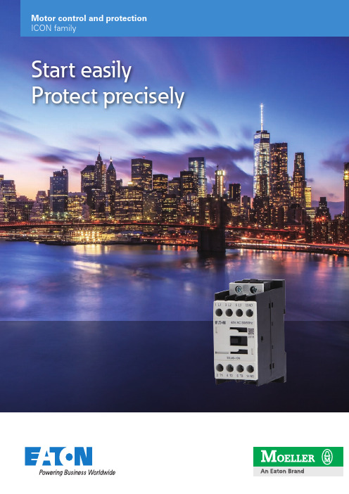
Motor control and protectionICON familyStart easily Protect preciselyIntroducing Eaton’s new contactor range for AC-3 applications to 170A. Perfectly suited for applications in the commercial and industrial segments for panel builders and machinery OEMs.The contactor has a smaller footprint than the existing xStart series and offers application adjusted ratings.Icon Contactors SeriesCoil voltages available are 24V50/60HZ, 110V50/60HZ, 230V50/60HZ, 400V50/60HZ, DC24V .Basic devices Rated operational current Max. motor rating for three-phase motors 50 - 60 Hz Conventional thermal current I th = I e AC-1at 40°C A Open Contact AC-3AC-3AC-4380 V 400 V I e220 V 230 V P 380 V 400 V P 660 V 690 V P 220 V 230 V P 380 V 400 V P 660 V 690 V P N/O = Normallyopened contact N/C = Normally 4 pole, 3 poleConnection type: Screw terminals9 2.5 4 4.5 1.5 2.5 3.6 20 – 1 N/C 12 3.5 5.5 6.5 2 3 4.4 20 1 N/O –12 3.5 5.5 6.5 2 3 4.4 20 – 1 N/C 15 4 7.5 7 2 3 4.4 20 1 N/O –154 7.5 7 2 3 4.4 20 – 1 N/C 3 poleConnection type: Screw terminals1857.511 2.5 4.56.5 401 N/O–18 5 7.511 2.5 4.5 6.5 40 – 1 N/C 257.51114 3.5 68.5 401 N/O–25 7.5 1114 3.5 6 8.5 40 – 1 N/C 32101515 4 710 451 N/O–32 10 1515 4 710 45 – 1 N/C 381118.515 4 710 451 N/O–3811 18.5 15 4 710 45 – 1 N/C 3 poleConnection type: Screw terminals40 12.5 18.523 5 912 60 1 N/O 1 N/C 50 15.5 2230 6 1014 80 1 N/O 1 N/C 65 20 3035 7 1217 98 1 N/O 1 N/C 7222 3735 7 1217 98 1 N/O 1 N/C 3 poleConnection type: Screw terminals80 25 3737112015110 1 N/O 1 N/C 95304545 1120151301 N/O1 N/C3 poleConnection type: Screw terminals115 37 5590 17 2843 160 ––150 48 75 96 20 3348 190 ––1705290140 20 3348 203––CMN00027DILM9-01N CMN00038DILM12-10N CMN00049DILM12-01N CMN00060DILM15-10N CMN00071DILM15-01N CMN00082DILM18-10N DILM18-01N CMN00104DILM25-10N DILM25-01N(CMN00126DILM32-10N DILM32-01N CMN00148DILM38-10N DILM38-01N CMN00170DILM40-11N DILM50-11N DILM65-11N DILM72-11N DILM80-11N DILM95-11N DILM115N DILM150N DILM170N (...)(...)(...)(...)(...)(...)(...)(...)(...)(...)(...)(...)(...)(...)(...)(...)(...)(...)(...)(...)(...)(...)• Phase failure sensitivity and temperature compensation • Reset pushbutton manual/auto • Test/off pushbutton• Auxiliary contact (1 N/O + 1 NC)•Fitted directly on the contactor of the maximum current to 175AIcon Overload relays ZB..N series0.1 – 0.16CMN00333CMN00335ZB12N-1,6CMN00336ZB12N-2,4CMN00337ZB12N-4CMN00338ZB12N-6CMN00339ZB12N-10CMN00340ZB12N-12CMN00341ZB12N-161 – 1.5CMN00352ZB32N-24CMN00353ZB32N-30CMN00354ZB32N-36CMN00355ZB32N-38CMN00356Setting range of overload releasesCircuit symbolAuxiliary contactFor use withI r AN/O = normally open contact N/C = normally closed contact0.4 – 0.6 1 N/O 1 N/C 0.6 – 1 1 N/O 1 N/C 1 – 1.6 1 N/O 1 N/C 1.6 – 2.4 1 N/O 1 N/C 2.4 – 4 1 N/O 1 N/C 4 – 6 1 N/O 1 N/C 6 – 10 1 N/O 1 N/C 9 – 12 1 N/O 1 N/C 12 –161 N/O1 N/C 17 – 24 1 N/O 1 N/C 22 – 30 1 N/O 1 N/C 29 – 36 1 N/O 1 N/C 33 – 381 N/O1 N/COverload relaysIcon Overloads ZB…N seriesSetting range of overload releasesCircuit symbolAuxiliary contactFor use withI r AN/O = normally open contact N/C = normally closed contact63 – 80 1 N/O 1 N/C 77 – 971 N/O1 N/C50 – 70 1 N/O 1 N/C 70 – 100 1 N/O 1 N/C 95 – 125 1 N/O 1 N/C 120 – 150 1 N/O 1 N/C 145 – 1751 N/O1 N/COverload relays Part no.Article no.– 25CMN00363– 50– 35– 25 – 50ZB95N-50 – 35ZB150N-35Icon Contactor Relays DILA…N seriesWiring method: Screw terminals Basic devices with interlocked opposing contacts ContactRated operational current AC – 15Conventional thermal current at 55°CN/O = Normally opened contact N/C = Normally closed contact220 V 230 V 240 V I e A380 V 400 V 415 V I e AI th A4 N/O – 4 416 3 N/O 1 N/C 4 4 16 2 N/O 2 N/C 4 4 16 1 N/O 3 N/C 4416–4 N/C4416DILA-40N DILA-31N DILA-22N DILA-13N DILA-04N(Coil voltages available are 24V50/60HZ, 110V50/60HZ, 230V50/60HZ, 400V50/60HZ, DC24V .• Varied 4-pole contact configurations • Conventional thermal current (Ith): 16A• Identical construction sizes for AC- and DC-operated contactor relays •Integrated surge suppressors for DC-operated contactor relaysA complete range of accessories are available for the Icon series, such as:• Auxiliary contacts (top mount)• Auxiliary contacts (side mount)• RC Suppressors• Varistor Suppressors• Pneumatic timer modules • Mechanical Interlocks • Sealable Shrouds•External Reset Button(...)(...)(...)(...)(...)E a t o n10 Kent RoadMascot NSW 2020Tel: 1300 332 866Fax: (02) 9693 1258Email: ************************ Eaton is a registered trademarkof Eaton Corporation.All trademarks are property of their respective owners.For more information about Eaton visit: Eaton’s mission is to improve the quality of life and the environment through the use of power management technologies and services. We provide sustainable solutions that help our customers effectively manage electrical, hydraulic, and mechanical power – more safely, more effi ciently, and more reliably. Eaton’s 2019 revenues were $21.4 billion, and we sell products to customers in more than 175 countries. We have approximately 95,000 employees.For more information about Eaton visit: 。
BCZ4系列高压直流接触器选型手册说明书
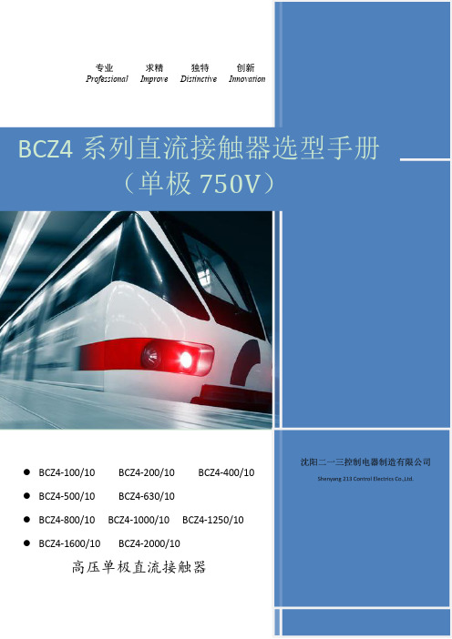
专业求精独特创新ProfessionalImproveDistinctiveInnovation●BCZ4-100/10BCZ4-200/10BCZ4-400/10●BCZ4-500/10BCZ4-630/10●BCZ4-800/10BCZ4-1000/10BCZ4-1250/10●BCZ4-1600/10BCZ4-2000/10高压单极直流接触器BCZ4系列直流接触器选型手册(单极750V )BCZ4系列高压直流接触器用途BCZ4系列直流接触器是我公司BCZ系列直流接触器的一款新开发产品额定工作电压1500VDC,最大工作电压1800V DC额定工作电流100A,200A,400A,500A,630A,800A,1000A,1250A,1600A,2000A。
适用于电力牵引机车、轨道交通、光伏发电以及电动汽车、蓄电池车辆的的起动、停止和电动叉车、通信电源等领域的电源切换及不间断电源系统。
符合标准《GB14048.1-2012低压开关设备控制设备第1部分总则》《GB14048.4-2010低压开关设备和控制设备第4-1部分:接触器和电动机起动器机电式接触器和电动机起动器(含电动机保护器)》《GB/T25890.1-2010轨道交通地面装置直流开关设备第1部分:总则 《GB/T25890.3-2010轨道交通地面装置直流开关设备第3部分:户内直流隔离开关、负荷开关和接地开关》《GBT17196-2017连接器件连接铜导线用的扁形快速连接端头安全要求》 《IEC60077-1》《IEC60077-2》型号及含义BC Z4-□/1022□线圈电压代号常开常闭辅助触头数量常开常闭主触头数量额定电流设计序号主回路为直流企业代号接线导线尺寸型号BCZ4-10020040063080012502000主电路铜排mm2根30x52根40x52根50x52根80x53根100x5导线mm235952402根1852根240主要技术参数产品型号BCZ4-100/10BCZ4-100/01BCZ4-200/10BCZ4-200/01BCZ4-400/10额定工作电流I e(DC-1)Rated Operational Current100A200A400A 额定绝缘电压U iRated Insulation Voltage690V1000V额定分断能力400VDC Rated Breaking Capacity L/R≤1ms100A200A400A L/R=15ms54A108A216A短路接通电流能力100msShort circuit current capability120A240A480A 临界电流Critical Current0A机械寿命Mechanical Endurance>106次电气寿命ElectricalEndurance>6×10⁵次Un.IeT<1ms操作频率≤6/min线圈工作电压范围(T a=70℃max)Coil Operating Range(80%~110%)U s订货代号及额定控制电压Ordering Code and Rated Control Supply Voltage B1:24V B2:48V B3:110V B4:220V AC:110V AC:220V AC:380V线圈功耗Coil PowerDissipation<12W<13W<21W 发热电流I th(Ta=70℃)Continuous Current100A200A400A 短时过载耐受电流(100ms)Short-time Overload Current2000A4000A8000A 重量Weight0.93kg 1.2kg 1.45kg 主触头材料Main Contacts Material AgSnO2污染等级Pollution DegreePD3过电压类别Overvoltage categoryOV3辅助触头配置Auxiliary Contacts nfiguration-1NO+1NC1NO+1NC辅助触头分断能力Auxiliary contact breaking capacity AC-15AC400V/2A AC24V-250V/4A AC380-440V/3A DC-13DC250V/0.3A DC110V-130V/1.2ADC48V/4A DC24V/8A产品型号BCZ4-500/10BCZ4-630/10额定工作电流I e(DC-1)Rated Operational Current500A630A额定绝缘电压U iRated Insulation Voltage2000V额定分断能力750VDC Rated Breaking Capacity1L/R≤1ms500A630A L/R=15ms270A340A短路接通电流能力Short circuit current capability5000A100ms6300A100ms 临界电流Critical Current0A机械寿命Mechanical Endurance>106次电气寿命ElectricalEndurance>6×10⁵次Un.IeT<1ms操作频率≤6/min 线圈工作电压范围(T a=70℃max)Coil Operating Range(80%~110%)U s订货代号及额定控制电压Ordering Code and Rated Control Supply Voltage B1:24V B2:48V B3:110V B4:220V AC:110V AC:220V AC:380V线圈功耗Coil Power Dissipation80W发热电流I th(Ta=70℃)Continuous Current500A630A 短时过载耐受电流(100ms)Short-time Overload withstand Current10kA12.6kA 重量Weight7kg主触头材料Main Contacts Material AgSnO2污染等级Pollution DegreePD3过电压类别Overvoltage categoryOV3辅助触头配置Auxiliary Contacts Configuration4×(1NO+1NC)4×snap-action Switch LXW2-11辅助触头分断能力Auxiliary contact breaking apacity AC-15AC400V/2A AC24V-250V/4AAC380-440V/3ADC-13DC250V/0.3A DC110V-130V/1.2ADC48V/4A DC24V/8A产品型号BCZ4-800/10BCZ4-1000/10BCZ4-1250/10额定工作电流I e(DC-1)Rated Operational Current800A1000A1250A额定绝缘电压U iRated Insulation Voltage2000V额定分断能力750VDC Rated Breaking Capacity L/R≤1ms800A1000A1250A L/R=15ms432A540A675短路接通电流能力100msShort circuit current capability8000A10000A12500A 临界电流Critical Current0A机械寿命MechanicalEndurance>106次电气寿命ElectricalEndurance>6×10⁵次Un.IeT<1ms操作频率≤6/min线圈工作电压范围(T a=70℃max)Coil Operating Range(80%~110%)U s订货代号及额定控制电压Ordering Code and Rated Control Supply Voltage Z1:24V Z2:48V Z3:110V Z4:220V AC:110V AC:220V AC:380V线圈功耗Coil PowerDissipation启动:<230W保持:<20W发热电流I th(Ta=70℃)Continuous Current800A1000A1250A 短时过载耐受电流(100ms)Short-time Overload Current16kA20kA25kA 重量Weight10kg主触头材料Main Contacts Material AgSnO2污染等级Pollution Degree PD3过电压类别Overvoltage categoryOV3辅助触头配置Auxiliary Contacts nfiguration2NO+2NC辅助触头分断能力Auxiliary contact breaking apacity AC-15AC400V/2A AC24V-250V/4A AC380-440V/3A DC-13DC250V/0.3A DC110V-130V/1.2ADC48V/4A DC24V/8A产品型号BCZ4-1600/10BCZ4-2000/10额定工作电流I e(DC-1)Rated Operational Current16002000额定绝缘电压U iRated Insulation Voltage2000V额定分断能力750VDC Rated Breaking Capacity L/R≤1ms:1600AL/R=15ms:864AL/R≤1ms:2000AL/R=15ms:1080A短路接通电流能力Short circuit current capability16000A100ms20000A100ms 临界电流Critical Current0A机械寿命Mechanical Endurance>106次电气寿命ElectricalEndurance>6×10⁵次Un.IeT<1ms操作频率≤6/min线圈工作电压范围(T a=70℃max)Coil Operating Range(80%~110%)U s订货代号及额定控制电压Ordering Code and Rated Control Supply Voltage B1:24V B2:48V B3:110V B4:220V AC:110V AC:220V AC:380V线圈功耗Coil PowerDissipation120W发热电流I th(Ta=70℃)Continuous Current1600A2000A 短时过载耐受电流(100ms)Short-time Overload Current32kA40kA 重量Weight27kg主触头材料Main Contacts MaterialAgSnO2污染等级Pollution DegreePD3过电压类别Overvoltage categoryOV3辅助触头配置Auxiliary Contacts nfiguration4×(1NO+1NC)4×snap-action Switch LXW2-11辅助触头分断能力Auxiliary contact breaking capacity AC-15AC400V/2A AC24V-250V/4A AC380-440V/3A DC-13DC250V/0.3A DC110V-130V/1.2ADC48V/4A DC24V/8A外形及安装尺寸60+-62542-?4.89650BCZ4-100/10BCZ4-200/10BCZ4-400/10BCZ4-500/10,BCZ4-630/10BCZ4-800/10,BCZ4-1000/10,BCZ4-1250/10BCZ4-1600/10,BCZ4-2000/10接线图BCZ4-□/10BCZ4-□/01BCZ4-□/20BCZ4-□/20UNBCZ4-□/20BCZ4-□/20UN注:UN代表产品主触点串联成单极使用。
美国Eaton公司产品说明书:Eaton Moeller系列xPole - mRB4 6 RCBO

Eaton 120654Eaton Moeller series xPole - mRB4/6 RCBO - residual-current circuit breaker with overcurrent protection. RCD/MCB, 16A, 100mA, B-LS-Char, 3N pole, FI-Char: AGeneral specificationsEaton Moeller series xPole - mRB4/6 RCBO - residual-current circuit breaker with overcurrent protection120654401508118484280 mm 75.5 mm 70 mm 0.446 kg CE Marked RoHS conformCE mRB6-16/3N/B/01-AProduct NameCatalog Number EANProduct Length/Depth Product Height Product Width Product Weight Compliances Certifications Model CodeSwitchgear for residential and commercial applicationsmRB6Combined RCD/MCB devicesSwitchgear for industrial and advanced commercial applications Three-pole + N44BB16 A6 - 25 Ampere0.1 AType A, pulse-current sensitiveRCBO AC400 V230 V / 400 V400 V500 V4 kV30, 100, 300 MilliAmpere Partly surge-proof, 250 A 50 HzA6 kA6 kA6 kA0.5 x I∆n6 kA6 kA6 kAApplicationProduct rangeBasic functionProduct applicationNumber of polesNumber of poles (protected) Number of poles (total) Tripping characteristic Release characteristicRated currentRated current of product range Fault current rating Sensitivity typeType Voltage typeVoltage ratingVoltage rating at ACRated operational voltage (Ue) - maxRated insulation voltage (Ui)Rated impulse withstand voltage (Uimp)Rated fault currents of product rangeImpulse withstand currentFrequency ratingLeakage current typeRated switching capacityRated switching capacity (IEC/EN 60947-2)Rated switching capacity (IEC/EN 61009)Rated non-tripping currentRated short-circuit breaking capacity (EN 60947-2) Rated short-circuit breaking capacity (EN 61009) Rated short-circuit breaking capacity (EN 61009-1) Rated short-circuit breaking capacity (IEC 60947-2)0 kA 0.25 kAUndelayed Non-delayed 100 Ampere gL 3III245 mm480 mm70 mmTri-stable slide catch - enables removal from existing busbar combinationIP20IP40Twin-purpose1 - 25 Square MillimeterBusbar tag shroud to VBG41 mm²25 mm²1 mm²25 mm²2 mmIEC 68-2: 25 °C - 55 °C at 90 % - 95 % humiditySurge current capacityDisconnection characteristic TrippingBack-up fuseSelectivity class Overvoltage category Pollution degree FrameWidth in number of modular spacingsDevice heightBuilt-in depthMounting styleDegree of protectionDegree of protection (built in)Terminals (top and bottom)Solid terminal capacitiesTerminal protectionConnectable conductor cross section (solid-core) - min Connectable conductor cross section (solid-core) - max Connectable conductor cross section (multi-wired) - min Connectable conductor cross section (multi-wired) - max Material thicknessClimatic proofing16 A0 W 11.6 W 0 W0 W-25 °C 40 °C Meets the product standard's requirements.Meets the product standard's requirements.Meets the product standard's requirements.Meets the product standard's requirements.Meets the product standard's requirements.Does not apply, since the entire switchgear needs to be evaluated.Does not apply, since the entire switchgear needs to be evaluated.Meets the product standard's requirements.Does not apply, since the entire switchgear needs to be evaluated.Meets the product standard's requirements.Does not apply, since the entire switchgear needs to be evaluated.Does not apply, since the entire switchgear needs to be evaluated.Is the panel builder's responsibility.Is the panel builder's responsibility.Is the panel builder's responsibility.Rated operational current for specified heat dissipation (In) Heat dissipation per pole, current-dependentEquipment heat dissipation, current-dependentStatic heat dissipation, non-current-dependentHeat dissipation capacityAmbient operating temperature - minAmbient operating temperature - max 10.2.2 Corrosion resistance10.2.3.1 Verification of thermal stability of enclosures10.2.3.2 Verification of resistance of insulating materials to normal heat10.2.3.3 Resist. of insul. mat. to abnormal heat/fire by internal elect. effects10.2.4 Resistance to ultra-violet (UV) radiation10.2.5 Lifting10.2.6 Mechanical impact10.2.7 Inscriptions10.3 Degree of protection of assemblies10.4 Clearances and creepage distances10.5 Protection against electric shock10.6 Incorporation of switching devices and components10.7 Internal electrical circuits and connections10.8 Connections for external conductors10.9.2 Power-frequency electric strengthIs the panel builder's responsibility.Is the panel builder's responsibility.The panel builder is responsible for the temperature rise calculation. Eaton will provide heat dissipation data for the devices.Is the panel builder's responsibility. The specifications for the switchgear must be observed.Is the panel builder's responsibility. The specifications for the switchgear must be observed.The device meets the requirements, provided the information in the instruction leaflet (IL) is observed.3Concurrently switching N-neutralIEC/EN 61009eaton-xpole-mrb4-rcbo-catalog-ca019058en-en-us.pdfeaton-xpole-mrb6-rcbo-catalog-ca019057en-en-us.pdfDA-DC-03_mRB-3N03_mRB-3p_20041603_mRB-3N_281118eaton-mcb-xpole-mrb4-6-characteristic-curve.epseaton-xeffect-frbm6/m-characteristic-curve-002.jpgDimensions xPole mRB4/mRB6 3Neaton-xeffect-frbm6/m-dimensions-004.jpgeaton-mcb-xpole-mrb4-6-dimensions.eps3D Drawing xPole mRB4/mRB6 3Neaton-xpole-combined-mcb-rcd-device-rcbo-packaging-manual-multilingual.pdfIL019140ZUDA-CS-faz_3pn_4pDA-CD-faz_3pn_4pCharacteristics xPole mRB4/mRB6 3Neaton-mcb-xpole-mrb4-6-wiring-diagram.epsContact Sequence xPole mRB4/mRB6 3N10.9.3 Impulse withstand voltage10.9.4 Testing of enclosures made of insulating material 10.10 Temperature rise10.11 Short-circuit rating10.12 Electromagnetic compatibility10.13 Mechanical function Current limiting class FeaturesStandards Catalogues Certification reports Characteristic curve DrawingsInstallation instructions mCAD modelTime/current curves Wiring diagramsEaton Corporation plc Eaton House30 Pembroke Road Dublin 4, Ireland © 2023 Eaton. All rights reserved. Eaton is a registered trademark.All other trademarks areproperty of their respectiveowners./socialmediaeaton-xeffect-frbm6/m-wiring-diagram-002.jpg。
EATON伊顿直流接触器

C80WN121
Cat. No. C80EH121 Size 3 —单极常开
100V线圈
目录号
C80DX14 C80DC14 C80DF14 C80DG14
C80DX24 C80DC24 C80DF24 C80DG24
C80EH141 C80EH441
C80FJ141 C80FJ441
伊顿电气有限公司 苏州工业园区苏虹西路193号 苏州工业园区苏虹中路306号 Tel: 0512-67163728 62585099 Fax: 0512-67169535 62585076 Postcode: 215021
Partner
版本号:CADC0012007C/CPG 本公司保留对样本资料的解释权和修改权, 且毋须另行通知. 2007.08
②对10-150A后连端接式接触器,定购上述前端连接式ME接触器和后端连接套件,目录号2184A10G08,(仅现场内安装)。
③要求面板钻孔。
④也提供其他线圈电压,见表4。目录号最后数字表示所需电压的替代后缀码,例如 MR510B。
表4:线圈电压代码选择
电压
65V (Me Size 仅为0-4) 115VDC 125VDC 230VDC 250VDC 550VDC 其它
应用描述
应用范围包括采矿、研磨、起重和运输。 这些接触器使用直流线圈。 注:若控制电压只有交流120V,则必 须使用整流器模块。
特点
铸钢操纵机构和电磁机构具有较高的 机械强度。 自润滑轴承; 触头寿命长。
标准和认证
CMAA 5.6.6-2 NEMA ICS3-441,442,443 NEMA ICS2-331.23 NEMA ICS2-110.05.02 NEMA ICS2-125.21.02
伊顿 200 A 熔断负荷断路弯头连接器更换保险丝安装 说明书

200 A Fused Loadbreak Elbow Connector Replacement Fuse Installation InstructionsDISCLAIMER OF WARRANTIES AND LIMITATION OF LIABILITYThe information, recommendations, descriptions and safety notations in this document are based on Eaton Corporation’s (“Eaton”) experience and judgment and may not cover all contingencies. If further information is required, an Eaton sales office should be consulted. Sale of the product shown in this literature is subject to the terms and conditions outlined in appropriate Eaton selling policies or other contractual agreement between Eaton and the purchaser.THERE ARE NO UNDERSTANDINGS, AGREEMENTS, WARRANTIES, EXPRESSED OR IMPLIED, INCLUDING WARRANTIES OF FITNESS FOR A PARTICULAR PURPOSE OR MERCHANTABILITY, OTHER THAN THOSE SPECIFICALL Y SET OUT IN ANY EXISTING CONTRACT BETWEEN THE PARTIES. ANY SUCH CONTRACT STATES THE ENTIRE OBLIGATION OF EATON. THE CONTENTS OF THIS DOCUMENT SHALL NOT BECOME PART OF OR MODIFY ANY CONTRACT BETWEEN THE PARTIES. In no event will Eaton be responsible to the purchaser or user in contract, in tort (including negligence), strict liability or otherwise for any special, indirect, incidental or consequential damage or loss whatsoever, including but not limited to damage or loss of use of equipment, plant or power system, cost of capital, loss of power, additional expenses in the use of existing power facilities, or claims against the purchaser or user by its customers resulting from the use of the information, recommendations and descriptions contained herein. The information contained in this manual is subject to change without notice.ii InstallatIon InstructIons MN132021EN November 2016ContentsDISCLAIMER OF WARRANTIES AND LIMITATION OF LIABILITY . . . . . . . . . . . . . . . . . . . . . . . . . . . . . . . . . . .ii SAFETY FOR LIFE . . . . . . . . . . . . . . . . . . . . . . . . . . . . . . . . . . . . . . . . . . . . . . . . . . . . . . . . . . . . . . . . . . . . . . . . .iv SAFETY INFORMATION . . . . . . . . . . . . . . . . . . . . . . . . . . . . . . . . . . . . . . . . . . . . . . . . . . . . . . . . . . . . . . . . . . . .iv Safety instructions (iv)PRODUCT INFORMATION . . . . . . . . . . . . . . . . . . . . . . . . . . . . . . . . . . . . . . . . . . . . . . . . . . . . . . . . . . . . . . . . . . .1 Introduction (1)Read This Manual First (1)Additional Information (1)Acceptance and Initial Inspection (1)Handling and Storage (1)Quality Standards (1)FUSE REPLACEMENT PROCEDURES . . . . . . . . . . . . . . . . . . . . . . . . . . . . . . . . . . . . . . . . . . . . . . . . . . . . . . . . .2 Probe and Elbow Housing Disassembly (3)Fuse Disassembly (4)Replacement Fuse Installation (6)Probe Adapter Reassembly (7)Elbow Housing and Probe Reassembly (8)iiiInstallatIon InstructIons MN132021EN November 2016iv 200 A Fused Loadbreak Elbow Connector Replacement FuseInstallatIon InstructIons MN132021EN November 2016Safety for lifeEaton meets or exceeds all applicable industry standards relating to product safety in its Cooper Power™ series products. We actively promote safe practices in the use and maintenance of our products through our service literature, instructional training programs, and the continuous efforts of all Eaton employees involved in product design, manufacture, marketing, and service.We strongly urge that you always follow all locally approved safety procedures and safety instructions when working around high voltage lines and equipment, and support our “Safety For Life” mission.Safety informationThe instructions in this manual are not intended as asubstitute for proper training or adequate experience in the safe operation of the equipment described. Only competent technicians who are familiar with this equipment should install, operate, and service it.A competent technician has these qualifications:●●Is thoroughly familiar with these instructions.●●Is trained in industry-accepted high and low-voltage safe operating practices and procedures.●●Is trained and authorized to energize, de-energize, clear, and ground power distribution equipment.●●Is trained in the care and use of protective equipment such as arc flash clothing, safety glasses, face shield, hard hat, rubber gloves, clampstick, hotstick, etc.Following is important safety information. For safeinstallation and operation of this equipment, be sure to read and understand all cautions and warnings.This manual may contain four types of hazard statements:Indicates an imminently hazardous situation which, ifnot avoided, will result in death or serious injury .Indicates a potentially hazardous situation which, if notavoided, could result in death or serious injury .Indicates a potentially hazardous situation which, if not avoided, may result in minor or moderate injury .CAUTIONIndicates a potentially hazardous situation which, if not avoided, may result in equipment damage only .Safety instructionsFollowing are general caution and warning statements that apply to this equipment. Additional statements, related to specific tasks and procedures, are located throughout themanual.Hazardous voltage . Contact with hazardous voltage will cause death or severe personal injury . Follow all locally approved safety procedures when working around high- and low-voltage lines and equipment .G103 .3Before installing, operating, maintaining, or testing this equipment, carefully read and understand the contents of this manual . Improper operation, handling ormaintenance can result in death, severe personal injury, and equipment damage .G101 .0This equipment is not intended to protect human life . Follow all locally approved procedures and safety practices when installing or operating this equipment . Failure to comply can result in death, severe personal injury and equipment damage .G102 .1Power distribution and transmission equipment must be properly selected for the intended application . Itmust be installed and serviced by competent personnel who have been trained and understand proper safety procedures . These instructions are written for suchpersonnel and are not a substitute for adequate training and experience in safety procedures . Failure to properly select, install or maintain power distribution and transmission equipment can result in death, severe personal injury, and equipment damage . G122 .21InstallatIon InstructIons MN132021EN November 2016Always consider the termination to be energized until the test point “No Voltage” indication is confirmed by other means . Failure to comply could result in death or severe personal injury .All associated apparatus must be de-energized during any hands-on installation or maintenance . Failure to comply could result in death, severe personal injury and equipment damage .Semi-Conducting ShieldSemi-Conductive Insert Current-Limiting Fuse Coppertop ConnectorDrain Wire T abLoadbreak BandProbe AdapterDrain Wire T ab EPDM InsulationLoadbreak ProbeArc FollowerPulling EyeT est PointFigure 1 . Line illustration of 200 A 25 kV Fused Elbow .Product InformationIntroductionThe 200 A, 15 and 25 kV Class Fused Loadbreak Elbow Connectors from Eaton combines a fully-shielded andinsulated plug-in termination with fullrange current-limiting fuse protection. The Fused Loadbreak Elbow Connector provides a convenient and cost effective means to adding fused protection to underground distribution systems, for connecting underground cables to transformers, switching cabinets and junctions equipped with loadbreak bushings.Read This Manual FirstRead and understand the contents of this manual and follow all locally approved procedures and safety practices before installing or operating this equipment.Additional InformationThese instructions cannot cover all details or variations in the equipment, procedures, or process described nor provide directions for meeting every possible contingency during installation, operation, or maintenance. When additional information is desired to satisfy a problem not covered sufficiently for the user’s purpose, please contact your Eaton representative.Acceptance and Initial InspectionEach current-limiting replacement fuse is completelyinspected and tested at the factory. It is in good condition when accepted by the carrier for shipment. Upon receipt of the current-limiting replacement fuse, inspect the connector thoroughly for damage and loss of parts incurred during shipment. If damage or loss is discovered, file a claim with the carrier immediately.Handling and StorageIf the current-limiting replacement fuse is to be stored for an appreciable time before installation, provide a clean, dry storage area. Locate the replacement fuse so as to minimize the possibility of physical damage.Quality StandardsISO 9001 Certified Quality Management System.2200 A Fused Loadbreak Elbow Connector Replacement FuseInstallatIon InstructIons MN132021EN November 2016Fuse Replacement ProceduresComplete current-limiting replacement fuse includes:●●Current-Limiting Fuse ●●Two (2) Spare Set Screws ●●Bleeder Strap●●Two (2) Probe Installation Tools ●●One (1) 1/8" Hex Wrench ●●Two (2) 3/16" Hex Wrenches ●●Silicone Lubricant●●Installation Instruction SheetHazardous Voltage . Both sides of the fused loadbreak elbow must be disconnected and grounded prior to any hands-on installation or maintenance . Failure tocomply will result in death or severe personal injury andequipment damage .The operator should always use personal protective equipment (insulated gloves, clampstick and eye protection) whenever operating the fused loadbreak elbow . The operator should always be in the best possible operating position, providing firm footing and enabling a secure grasp of the clampstick, while maintaining positive control of the elbow before, during and immediately after operation . If there is any question regarding the operator’s operating position, de-energize the elbow before operation . The operator should not be looking directly at the connector during the moment of circuit interruption or connection . Failure to complycould result in death or serious injury .Capacitive T est Point Operating Instructions: Use only voltage indicating instruments specifically designed for test points . Use of conventional voltage sensing devices may provide false “No Voltage” indications .The test point must be dry and free of contaminants when checking for voltage . After indication is taken: clean, dry, and lubricate the test point cap with silicone grease and assemble to the test point .Always consider the termination to be energized until the test point “No Voltage” indication is confirmed by other means . Failure to comply could result in death or severe personal injury .Step 1Voltage T est OperationThe Fused Loadbreak Elbow Connector is equipped with two integral capacitive test points that can be used to establish whether or not the fuse has interrupted the tap circuit. The test point on the source side of an open fuse will indicate a voltage while the test point on the tap side of the fuse will indicate no voltage. Both test points will indicate a voltage if the fuse has not operated.Step 2Establish visible break and visible groundUsing a clampstick, isolate fuse by disconnecting the Fused Loadbreak Elbow Connector from the apparatusbushing and parking the Fused Loadbreak Elbow Connector on an appropriate feedthru device. Install an insulatedprotective cap on the apparatus bushing. Isolate the Fused Loadbreak Elbow Connector on the tap-end of the fuse by disconnecting and placing the tap-end cable termination on an appropriate feedthru device. Install an insulated protective cap on the tap-end apparatus bushing. Then create a visibly traceable ground on both sides of the fuse.3200 A Fused Loadbreak Elbow Connector Replacement FuseInstallatIon InstructIons MN132021EN November 2016Probe and Elbow Housing DisassemblyStep 3After a visible ground is achieved on both sides of the fuse, remove the Fused Loadbreak Elbow Connector from feedthru device.Step 4Install supplied wire probe wrench into wrench hole of loadbreak probe. Turning counterclockwise, unthread and remove loadbreak probe from fused loadbreak elbow.Drain WiresStep 5Detach drain-wire lead from the drain-wire eye of theelbow housing. At the overlap of elbow housing and cable housing, insert supplied bleeder strap approx. 1/2" (13 mm) under lip of elbow housing. Slide strap around the entire circumference of fused loadbreak elbow to vent the interfaces. Leave the bleeder strap inserted between housings.Elbow HousingProbe RemovedElbow and Cable Housing Overlap4InstallatIon InstructIonsMN132021EN November 2016Step 6Gripping the square portion of the cable housing, andkeeping the cable housing stationary, apply a twist-and-pull motion to the elbow housing to separate it from the cable housing.ote:N A screwdriver through the pulling eye on top of theelbow will aid in twisting and pulling to separate.Discard bleeder strap after housings are separated.Cable HousingGrip While SeparatingFacing OutwardSeparateStep 7Using the supplied 1/8" hex wrench, unthread the two set screws from the probe adapter.5200 A Fused Loadbreak Elbow Connector Replacement FuseInstallatIon InstructIons MN132021EN November 2016Step 8Remove probe adapter from fuse end cap stud on top of fuse.Probe AdapterFuse End Cap StudStep 9Gripping the square portion of the cable housing, use the supplied 3/16" hex wrench to loosen and unthread fuse from cable housing.6200 A Fused Loadbreak Elbow Connector Replacement FuseInstallatIon InstructIons MN132021EN November 2016Replacement Fuse InstallationStep 10Remove old fuse from cable housing.Remove Old FuseThreaded EndStep 11Thread fuse clockwise by hand and start threads into the connector in bottom of the cable housing until hand-tight.Insert Replacement FuseThreaded End7200 A Fused Loadbreak Elbow Connector Replacement FuseInstallatIon InstructIons MN132021EN November 2016Probe Adapter ReassemblyStep 12Holding the square portion of the cable housing, complete fuse assembly using the supplied 3/16" hex wrench. Tighten until fuse bottoms and the hex wrench twists.Confirm check dimension shown in illustration above. Position the long end of the hex wrench on the cablehousing nosepiece, verify that the top of the fuse end cap is equal to or below indicator notch on the hex wrench.Indicator NotchStep 13Install probe adapter on unthreaded stud. Probe adapter should rest flush on top of fuse end cap.Fuse End Cap8200 A Fused Loadbreak Elbow Connector Replacement FuseInstallatIon InstructIons MN132021EN November 2016Elbow Housing and Probe ReassemblyStep 14IMPORTANTAlign the flats of the probe adapter parallel to the nosepiece of the bushing.Assemble set screws into the probe adapter.Using supplied 1/8" (3 mm) hex wrench, thread the two set screws until they bottom out on the end post of the fuse, then tighten each set screw an additional 1/8 - 1/4 turn until tight.Parallel to the Nosepiece of the BushingLoadbreak Bushing InsertStep 15Using supplied lubricant, clean and lubricate elbow and cable interfaces.Assemble elbow housing onto the cable housing. Make sure the test point is facing outward away from the frontplate of the apparatus.Clean and Lubricate Supplied Lubricant9200 A Fused Loadbreak Elbow Connector Replacement FuseInstallatIon InstructIons MN132021EN November 2016Step 16Push down and twist elbow housing to align the probe adapter. The threaded hole in the probe adapter should be centered with respect to the hole in the elbow housing and perpendicular to the probe axis. By hand, insert loadbreak probe into the elbow housing along the center axis of the interface and thread the probe into the probe adapter. A thin layer of silicone lubricant applied to the last 1/4" (6 mm) of the probe body (not on the threads) can aid in installation.After at least three turns or when the probe is seated (5-1/2 turns) onto the probe adapter, use provided installation tool to properly torque the loadbreak probe. Proper torque is applied when the tool twists at least 180° (1/2 turn).ote:N If a different installation tool is used it must apply atorque of 100 to 120 lbf-in (11.0 – 13.5 N-m).Re-attach drain wire lead to the drain wire eye of the elbow housing.Clean and lubricate bushing and elbow housing interfaces areas with a thin, uniform coating of the silicone provided. Do not connect two different phases of a multiple-phase system. Before closing a single-phase loop, make certain both ends of the loop are the same phase.Step 17After the fuse has been replaced, using a clampstick,install the Fused Loadbreak Elbow Connector back onto the grounded feedthru device.Step 18Using a clampstick, remove the insulated protective cap from the tap end apparatus bushing. Install the tap end cable termination onto the tap end bushing using the appropriate procedure for the tap end cable termination.Step 19Using a clampstick, remove the insulated protective cap from the apparatus bushing and the Fused Loadbreak Elbow Connector from the feedthru device. Install the Fused Loadbreak Elbow Connector onto the apparatusbushing using the standard loadmake operating procedures described in Step 20.ote:N Before installing the Fused Loadbreak ElbowConnector back onto the apparatus bushing, the cause for the fuse operation should be remedied.Drain Wires10200 A Fused Loadbreak Elbow Connector Replacement FuseInstallatIon InstructIons MN132021EN November 2016Step 20Operating ProceduresLoadmake Operation●●Area must be clear of obstructions or contaminants that would interfere with the operation of the fused loadbreak elbow.●●Securely fasten a clampstick to the pulling eye of the fused loadbreak elbow.●●Place the fused loadbreak elbow over the bushing, inserting the white arc follower of the probe into the bushing approximately 2 1/2" (65 mm) until a slight resistance is felt. This will align and stabilize the fused loadbreak elbow.●●Turn your back to the bushing and grasp the clampstick securely and obtain good footing. Slam the fused loadbreak elbow onto the bushing with one quick and continuous motion.●●Turn around and apply a force to the clampstick to push the fused loadbreak elbow onto the bushing. A popping or snapping sound is often heard when this operation is performed.●●To check that the fused loadbreak elbow is properlylatched apply a gentle pull force to the clampstick. When latched properly the fused loadbreak elbow will not slide back off of the bushing.●●As a last operation, push on the clampstick to seat the fused loadbreak elbow all the way onto the bushing again. This insures that the fused loadbreak elbow is latched and was not dislodged during the latching check in previous step above.Fault Close1. It is not recommended that operations be made onknown faults.2. If a fault is experienced, the fused loadbreak elbowconnector, probe, and the bushing must be replaced.Loadbreak Operation●●Area must be clear of obstructions or contaminants that would interfere with this operation.●●Use clampstick to secure standoff insulator or portable feedthru in bracket. Ground devices to system ground per appropriate Installation Instructions. All associated apparatus must also be grounded.●●Secure fused loadbreak elbow eye firmly onto clampstick and lock.●●Twist clampstick clockwise until the fused loadbreak elbow rotates slightly on bushing — about 1/4" (6 mm). This action will break any surface friction between outer surface of bushing and inner surface of fused loadbreak elbow.●●Withdraw fused loadbreak elbow from bushing with a fast, firm, straight motion. Minimum amount of travel of fused loadbreak elbow to break load is 9" (230 mm).●●Use clampstick to place fused loadbreak elbow onlubricated standoff insulator or portable feedthru. (Follow loadmake instructions.)●●Place an insulated protective cap with ground wire attached to system ground on any exposed energized bushing using clampstick. Follow the same operating procedures as for the fused loadbreak elbow as outlined above under Loadmake Operation.11200 A Fused Loadbreak Elbow Connector Replacement FuseInstallatIon InstructIons MN132021EN November 2016his page is intentionally left blank.TEaton1000 Eaton Boulevard Cleveland, OH 44122United StatesEaton’s Power Systems Division 2300 Badger Drive Waukesha, WI 53188United States/cooperpowerseries© 2016 EatonAll Rights ReservedPrinted in USAPublication No. MN132021EN November 2016Eaton is a registered trademark.All trademarks are propertyof their respective owners.For Eaton‘s Cooper Power series productinformationcall 1-877-277-4636 or visit:/cooperpowerseries.。
AVITEQ振动器MVE50-4讲解
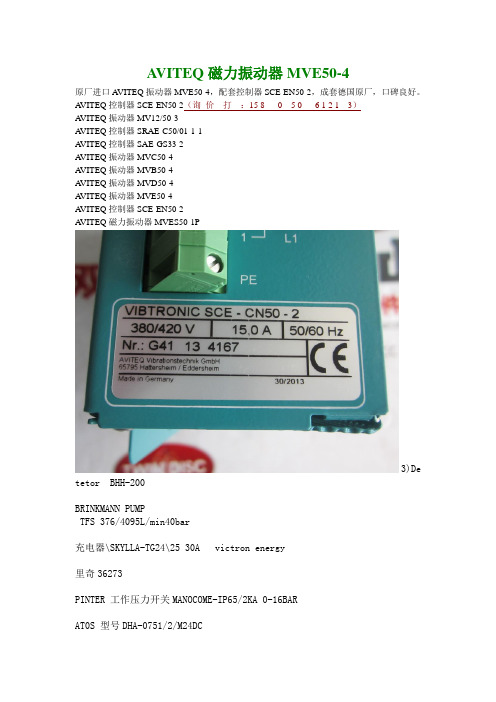
A VITEQ磁力振动器MVE50-4原厂进口A VITEQ振动器MVE50-4,配套控制器SCE-EN50-2,成套德国原厂,口碑良好。
A VITEQ控制器SCE-EN50-2(询价打:15 8 0 5 0 6 1 2 1 3)A VITEQ振动器MV12/50-3A VITEQ控制器SRAE-C50/01-1-1A VITEQ控制器SAE-GS33-2A VITEQ振动器MVC50-4A VITEQ振动器MVB50-4A VITEQ振动器MVD50-4A VITEQ振动器MVE50-4A VITEQ控制器SCE-EN50-2A VITEQ磁力振动器MVES50-1P3)De tetor BHH-200BRINKMANN PUMPTFS 376/4095L/min40bar充电器\SKYLLA-TG24\25 30A victron energy里奇36273PINTER 工作压力开关MANOCOME-IP65/2KA 0-16BARAT0S 型号DHA-0751/2/M24DCDAMCOS 160B4171 指示灯开关卡特蓄电池 9X-9730品牌:麦塔雷斯型号:MHP350A198EVAB207迪创迪创火焰探头X5200A4N13W2,防护等级TP56&ExdIIBT4IDC通讯板(与上面的探头配套的)006642-005电源底板(与上面的探头配套的)006590-003迪创火焰探头PIR9400A3A1AW,防护等级IP56&ExdIIBT4IDC通讯板(与上面的探头配套的)006642-004电源底板(与上面的探头配套的)006586-002LM303摩菲的油位保持器摩菲 DVU150 (55700299) 排泄阀FEDERAL SIGNAL CORPORATION 防爆对讲机正确型号310X-MVCULTER-HAMMER 接触器6702ED584BLAGDON气动隔膜泵B25 1AAABBTTSautronica 16BAR编号40766订货型号是GT300C2G16HYPRO水泵9304C-HM1CViatran PRESSURE TRANSDUCER, MODEL 245, 0-700KPa,0-5 VDC OUTPUT model: 245AMGX1691B加热器\CX/15397-02\380V/6.6KW\CALORITECH阿密龙 3019 95 GPM1.5 黄铜手枪式DYNALCO速度开关SW-200BSPM 2A26611BREVINI 减速机 CTU3200.1 S.N.:728815VS2 开关摩菲MEDC BGEQ4B6B2DDA7RAUTRONICA EAC-300A/B Processor cardDANIAMANT TYPE:L1611)detectormodel : 116-5861-011.5300, MODEL NO.HC300PLB7A2W1; DATE CODE:08DEC057674阿美特克3050水分析仪校验管 305431901SBLAGDON气动隔膜泵B25 1AAABBTTS泰科探头601FEX-MPRICE PUMP3MS50SS-412-21211-100-30-1T5真空泵HITECH INSTRUMENTS氧电池 813-9050WOMA安全阀 G1/2 S8.5 135Bar 1件件号是001.1108autronica detector1)BHH-320/X12)BDH-5003)BDH-500/N4)BDH-500/EX康士廉Part.no 001155 SALWICO本迪克斯 450修井机CAT3408空气压缩机GMC SINEAXModel:808-12120000TRANSMITTERREF:128802本迪克斯干燥器1A-592\AD-2品牌:OLAER奥莱尔型号:ELM0.75-210/00/AFSOLDO品牌限位开关型号: SX02200-2型号: SXC4200-2型号: SX73201-2德鲁克压力传感器PTX-5072-TC-A1-CA-H1-PR巴士德传感器 9692X-1CC-3-BNETSAFETY PHOENIX三频火焰探测器 IR3S-R品牌 WANNER型号 G40XDSNNNNCBMaker: MMC INTERNATIONAL CORP.Type: MMC SAMPLING DEVICE PART NO.:2326C1821540M1/2 40M Closed Self Contained Sampling UnitMaker: MMC INTERNATIONAL CORP.Type: MMC SAMPLING DEVICE PART NO.:S-2562-TS-CPL-SHT TS AdaptorVEGA 型号:PS68.XXE1H2HANAKQualitrol1)092-052-012)CAS-724-1+FLA-644-13)CAS-724-1+FLA-644-1+GAS-046-6EVAC蓝色接口6540524EVAC铜阀套5980800EVAC控制器6541675EVAC控制器5775500Evac冲水按钮3510100Evac水压阀5774002EVAC配件6541056EVAC配件5779400EVAC配件5779500EVAC配件5430103EVAC配件5980800EVAC配件5800000EVAC排气阀5435015Evac水压阀5774000EVAC按钮5900200EVAC气动按钮5900204EVAC带适配器法兰的活化剂6541675EVAC灰水阀6542811EVAC连接套筒5433572EVAC止回阀5959902EVAC橡胶膜片5435169EVAC执行机构5775500EVAC背板总成5780000DNH室内扬声器[][HS-8EEXMNT][]室内扬声器[][HP-10T][]防爆扬声器[][DSP-15EEXMNT][]哈威 V30D-140 RDN-2-1-04 LSN250-1杰斯曼联动台 KST19+KFS10威创压力传感器5705BPSX1052RGS ELECTRO PNEUMATICS LTDModel:VSK1001 SEALS FOR RGS 1''BSP 3 PORT SPOOL CONTROL VALVE H1003-9品牌:BITZERCOMPRESSOR\6H35.2-40P\BITZER REFRIGERATIOTR 编码器/CE100M.ArT.Nr100.00390摩菲室外防雨型振动开关VS2-IP67NUFLO CAMERON:1.Make: NUFLO CAMERON,Model: Turbine Flow Meter ,P/N: 9A-100062687,2.Make: NUFLO CAMERON,Model: Turbine Flow Meter ,P/N: 9A-100062810,3.Make: NUFLO CAMERON,Model: Turbine Flow Meter ,P/N: 9A-100009810,BRINKMANN TFS376/40+001resQmaxmodel:KIT411model:KIT457AMETEK陶瓷过滤器74422SE氧化锆锆头71785SEAUTRONICA控制板模块BSJ-310控制板模块BSD-310控制板模块BSL-310控制板模块BSS-310A世伟洛克Swagelok高压阀.DN12 6000psi.SS-6NBSW8T-G.316SS高压阀门.DN6 PN35.SS-6HNBSW8T-GSMOKE DETECTOR\BHH-500 SMOKE DETECTOR\BHH-500\AUTRONICA FIRE AND SECURITY\火气系统美国SAMSON电磁阀 type 3962, 24VDC, 3/2-way, IP 66, Eex d IIC T6, elec conn. 1/2"NPTLEROY SOMER电机3-LSES225MR-T N703333H11003 2011 IP55IK08 S1 DE:6313ZZC3 NDE:6313ZZC3 △400V 50HZ 1471min-145KW 84Ametrix振动探头5485C-007-040-M13776寸流量计为CAMERON 型号:9A-100062997,Rev.02,显示速度和总量;大8位3 / 4”显示器;电池采用一个“D”型1.5伏碱性电池。
- 1、下载文档前请自行甄别文档内容的完整性,平台不提供额外的编辑、内容补充、找答案等附加服务。
- 2、"仅部分预览"的文档,不可在线预览部分如存在完整性等问题,可反馈申请退款(可完整预览的文档不适用该条件!)。
- 3、如文档侵犯您的权益,请联系客服反馈,我们会尽快为您处理(人工客服工作时间:9:00-18:30)。
-
-
-
Yes
2
125V DC④
No
2
Yes
2
125V DC④
No
2
Yes
2
125V DC④
No
2
Yes
2③ 125V DC④
Yes
2③ 125V DC④
ME②
MR510C MR501C MR610C MR601C MR710C MR701C
MR810C
MR910C
①也提供其他线圈电压,见表4。目录号最后数字表示所需电压的替代后缀码,例如 ME010B。
1NO
1NO
连锁方式
机械
电气
磁线圈电压
4
Yes
2 4
125V DC①
2
4
Yes
2 4
125V DC①
2
4
Yes
2 4
125V DC①
2
4
Yes
2 4
125V DC①
2
4
Yes
2 4
125V DC①
2
Yes
2
125V DC①
No
2
Yes
2
125V DC①
No
2
Yes
2
125V DC①
No
2
Yes
3
125V DC①
.63(15.9)
1.88 1.25 (47.6) (31.8)
移除弧道
6.25 (158.8)
12.13 (308.0)
距地面间隙
1.38 (34.9)
1.00(25.4)
.50 (12.7)
.50(12.7) 1.88(26.3)
产品选型
当定购指定产品
■ 具有要求附件的编号
表2: 直流米尔型接触器产品选型
框架尺寸
极数
磁吹线圈 额定电流
开放式接触器 230V线圈 目录号
1NO 2
2NO
3
1NO 1NC
4
1NO 1NC
5
1NO 1NC
6
1NO 1NC
6A
1NO
8
1NO
None 5 25 50
None 5 25 50
100 100
特点
电源电路绝缘屏为聚酯玻璃材料塑造, 具有很高的抗弧和弧径能力; DPM设计安装在槽或角型结构里,但 也适合安装在金属或绝缘面板上; 可带或不带过流闭锁机构,在大过载 电流下防止分闸。当线电流回到正常, 过流锁脱开。
优点
弧道出口设置在单元前部,节省了面 板空间。接触器上面无需引弧间隙。 所有关键部件可从前面移动,无需拆 除进线和负载测电缆,易维护。安全 是必须的。当弧罩移开或没有正确安 装时,机械联锁防止接触器合闸。
MD810C
MD910C
更多信息请访问:
CADC0012007C
伊顿直流接触器产品目录
5
2007 年 11月
后端连接 0-4 5
6
7
8 9
10-150 300 600 900
1350 2500
-
1NO 1NC 1NO 1NC 1NO 1NC
1NO
1NO
Yes
3
125V DC①
目录号
ME010C ME020C ME011C ME001C
ME110C ME120C ME111C ME101C
ME210C ME220C ME211C ME201C
ME310C ME320C ME311C ME301C ME410C ME420C ME411C ME401C MD510C MD501C MD610C MD601C MD710C MD701C
150 150
300 300
600 600
810
13ቤተ መጻሕፍቲ ባይዱ0
C80DX12 C80DC12 C80DF12 C80DG12
C80DX22 C80DC22 C80DF22 C80DG22
C80EH121 C80EH421
C80FJ121 C80FJ421
C80GK121 C80GK421
C80JL121 C80JL421
伊顿电气有限公司 苏州工业园区苏虹西路193号 苏州工业园区苏虹中路306号 Tel: 0512-67163728 62585099 Fax: 0512-67169535 62585076 Postcode: 215021
Partner
版本号:CADC0012007C/CPG 本公司保留对样本资料的解释权和修改权, 且毋须另行通知. 2007.11
更多信息请访问:
6 伊顿直流接触器产品目录
2007 年 11月
尺寸
1.00(25.4)
4.00 2.00(50.8)
(101.6)
1.00(25.4)
.44(11.1)直径 -2安装孔 .38-16 Tap 1.00(25.4)深 2进线端孔
重量=30.5磅(13.8kg)
C80KM121
C80WN121
Cat. No. C80EH121 Size 3 —单极常开
100V线圈
目录号
C80DX14 C80DC14 C80DF14 C80DG14
C80DX24 C80DC24 C80DF24 C80DG24
C80EH141 C80EH441
C80FJ141 C80FJ441
应用描述
应用范围包括采矿、研磨、起重和运输。 这些接触器使用直流线圈。 注:若控制电压只有交流120V,则必 须使用整流器模块。
特点
铸钢操纵机构和电磁机构具有较高的 机械强度。 自润滑轴承; 触头寿命长。
标准和认证
CMAA 5.6.6-2 NEMA ICS3-441,442,443 NEMA ICS2-331.23 NEMA ICS2-110.05.02 NEMA ICS2-125.21.02
前缀代号
A B C D E F G
DPM系列1000V直流接触器
Cat. No. 2120A0/G02 DC Contactor
产品描述
DPM系列1000V直流特殊用途接触器 可在恶劣环境和振动情况下使用。接 触器为单元结构,组装在塑壳绝缘基 座上,在最小空间内提供最大的性能。
应用描述
该设备可用于铁路车辆、海上钻井、 采矿、越野汽车、船舰等。
作为伊顿公司的第一大业务部门,电气集团2006年的销售额达到42亿 美元,电气集团在电气控制、配电、工业控制和电能质量的制造和服务领域位 于全球领先地位,在设计、研发、制造和应用方面上给予用户提供最优质的服 务以及最先进的产品。通过一系列的收购和兼并计划,伊顿电气集团有以下成 功的著名品牌,如:Westinghouse®,Holec®,Cutler-Hammer®, Heinemann®和Powerware®,同时伊顿电气集团继承并发扬了这些著名公司 的技术和工程经验。伊顿持续坚持这些著名品牌的传统和发扬她们的独特优 点,为中国乃至全世界的客户提供有效的解决方案和服务。详细情况可以访 问:。
②对10-150A后连端接式接触器,定购上述前端连接式ME接触器和后端连接套件,目录号2184A10G08,(仅现场内安装)。
③要求面板钻孔。
④也提供其他线圈电压,见表4。目录号最后数字表示所需电压的替代后缀码,例如 MR510B。
表4:线圈电压代码选择
电压
65V (Me Size 仅为0-4) 115VDC 125VDC 230VDC 250VDC 550VDC 其它
技术数据和规格
电流范围:5-1800A 电 压:115,550V DC 机械寿命:2千万次 电 寿 命:50万次
表1: 直流米尔型接触器目录编号体制
C80 E H
4
2
1
N
2
0
基本目录编号 NEMA 尺寸 磁吹线圈等级
电极配置 线圈电压
辅助型号右位置② 辅助型号左位置② 辅助触头安装选择② 安装类型选择①
C80GK141 C80GK441
C80JL141 C80JL441
C80KM141 C80WN141
机械联锁
目录号
C81DDA11
C81DDA12
C81DEA11 C81DEA11 C81DGA11 C81DJA11 C81DJA11 C81DLA11
CADC0012007C
更多信息请访问:
1
25
2
50
3
100
4
150
5
300
6
600
7
900
8
1350
9
2500
辅助触点
1NO 2NO 1NO,1NC 1NC
1NO 2NO 1NO,1NC 1NC
1NO 2NO 1NO,1NC 1NC
1NO 2NO 1NO,1NC 1NC 1NO 2NO 1NO,1NC 1NC 1NO 1NC 1NO 1NC 1NO 1NC
①A=侧装;B=底部左侧和右侧装;C=底部左侧或右侧装;N=无 ② 1=1常开;2=2常开;3=1常闭1常开;4=1常闭;5=2常闭;0=无
更多信息请访问:
CADC0012007C
伊顿直流接触器产品目录
3
2007 年 11月
Cat. No. C80EH121 Size 3 —单极常开
4 伊顿直流接触器产品目录
2007 年 11月
600V 直流接触器
产品描述
这些接触器用在不稳定的直流电压中, 提供持久服务,易安装、维护。
应用描述
应用范围包括采矿、研磨、起重和运输。 这些接触器使用直流线圈。 注:若控制电压只有交流120V,则必 须使用整流器模块。
特点