多功能运动控制模块说明书
控制器说明书-CM55D运动控制器中性说明书
路采取防反接措施,能有效避免客户接错烧坏控制器。两路电源分别接 24V 开关电源。
&0' 微数控定义
24V 开关电源定义
V
+ 24V 开关电源 1
G
-
0V
- 24V 开关电源 2
24V
+
当输入输出少且负载小,也可以选择下图接线方式
&0' 微数控定义
24V 开关电源定义
V
+ 24V 开关电源 1
作为多普康自动化第二代微数控产品,在系统稳定性方面大大提高,脉冲频率的提高,使控制系统 最高加工速度大大提高。可广泛作为雕刻机、电焊机、数控机床、切割机、激光照排、绘图仪、贴标 机、包装机械等控制系统。
□ X、Y、Z、C 四轴控制 □ 2ms 插补周期 □ 单轴直线插补输出脉冲频率:400K □ 圆弧插补输出脉冲频率:300K □ 四轴直线插补输出脉冲频率:350K □ 非联动四轴输出脉冲频率:100K □ 支持中文、英文显示,由参数选择 □ 参数选项新增解释说明,简单明了 □ 28 点通用输入/12 点通用输出(高配版为 37 点通用输入/22 点通用输出) □ 具有掉电记忆功能 □ 支持时间锁机功能 □ 具有软限位选择
□ 安全功能
报警输入、急停输入
硬件行程的正负限位
软件行程的正负限位
□ 指令表
指令
指令
指令
相对运动
回机械零
PLC 设定
绝对运动
速度模式
顺圆 IJ
暂停
工件置数
逆圆 IJ
输出
工件计数
连续模式
循环
子程序调用
模拟量输出
顺圆运动
子程序开始
非联动速度
多普康 TC55V 运动控制系统 1-4 轴系列说明书

TC55V 运动控制系统1-4轴系列说明书北京多普康自动化技术有限公司安全须知使用本控制系统前,请您仔细阅读本手册后再进行相关的操作。
仔细阅读本操作说明书,以及用户安全须知,采取必要的安全防护措施。
如果用户有其他需求,请与本公司联系。
工作环境及防护:1.控制系统的工作温度为0-40℃,当超出此环境温度时系统可能会出现工作不正常甚至死机等现象。
温度过低时,液晶显示器将出现不正常的情况。
2.相对湿度应控制在0-85%。
3.在高温、高湿、腐蚀性气体的环境下工作时,必须采取特殊的防护措施。
4.防止灰尘、粉尘、金属等杂物进入控制系统。
5.应防护好控制系统的液晶屏幕(易碎品):使其远离尖锐物体;防止空中的物体撞到屏幕上;当屏幕有灰尘需要清洁时,应用柔软的纸巾或棉布轻轻擦除。
系统的操作:系统操作时需按压相应的操作按键,在按压按键时,需要食指或中指的指肚按压,切忌用指甲按压按键,否则将造成按键面膜的损坏,而影响您的使用。
初次进行操作的操作者,应在了解相应功能的正确使用方法后,方可进行相应的操作,对于不熟悉的功能或参数,严禁随意操作或更改系统参数。
由于使用产品不当,而造成危及人身、财产安全的责任,本公司概不负责。
系统的检修:当系统出现不正常的情况,需检修相应的连接或插座连接处时,应先切断系统电源。
再进行必要的检修。
未进行严格操作的技术人员或未得到本公司授权的单位或者个人,不能打开控制系统进行维修操作,否则后果自负。
系统保修说明:保修期:本产品自出厂之日起十二个月内。
保修范围:在保修期内,任何按使用要求操作的情况下所发生的故障。
保修期内:保修范围以外的故障为收费服务。
保修期外:所有的故障均为收费服务。
以下情况不在保修范围内:任何违反使用要求的人为故障或意外故障,尤其电压接反接错。
带电插拔系统连接插座而造成的损坏。
自然灾害等原因导致的损坏。
未经许可,擅自拆卸、改装、修理等行为造成的损坏。
其他事项:本说明书如有与系统功能不符、不详尽处,以系统软件功能为准。
威科达运动控制器 6 系列安装指南说明书
目录目录第一章产品检查及注意事项 (1)1.1开箱检查 (1)1.2运动控制器的型号说明 (1)1.3运动控制器的外形示意图 (2)1.4运动控制器储存环境 (2)1.5运动控制器使用环境 (2)1.6运动控制器的使用注意事项 (3)1.6.1安全注意事项 (3)1.6.2设计方面注意的事项 (3)1.6.3接线方面的注意事项 (3)1.6.4启动、维护时的注意事项 (4)1.6.5废弃时的注意事项 (4)1.7运动控制器的安装注意事项 (4)1.7.1运动控制器的安装方式 (4)1.7.2运动控制器的拆卸 (5)1.7.3运动控制器的摆放 (5)第二章产品介绍 (6)2.1术语与解释 (6)2.2威科达运动控制器简介 (6)2.3典型系统连接图 (7)2.4运动控制器接线端口说明 (7)第三章端子说明及配线 (10)3.1端子定义说明 (10)3.1.1数字IO跳线选择 (10)3.1.2数字量输入接线 (10)3.1.3数字量输出接线 (11)3.1.4RS-232(COM1)接口定义 (12)3.1.5RS-485接口定义 (12)目录3.1.6系统24V供电接口定义 (13)3.1.7数字IO供电接口定义 (13)3.1.8轴接口定义 (14)3.1.9模拟量输入定义 (16)3.1.10模拟量输出定义 (16)3.2运动控制器与伺服驱动器的连接 (17)3.2.1威科达伺服驱动器 (17)3.2.2台达伺服驱动器 (18)3.2.3三菱伺服驱动器 (19)3.2.4富士伺服驱动器 (20)3.2.5松下伺服驱动器 (21)3.2.6安川伺服驱动器 (22)第四章附录 (23)附录一:安装尺寸 (23)附录二:扩展模块概述 (26)第一章产品检查及注意事项第一章产品检查及注意事项1.1开箱检查感谢您选用威科达运动控制器!为了防止产品在购买与运输过程中的疏忽,请仔细检查下列项目:查看产品的铭牌是否与外包装一致;检查产品外观是否有划伤或者机械损伤;查看产品清单,核对配件是否齐全;轻摇机箱,查看内部是否有异物。
YASKAWA 机器控制器MP2200 MP2300 运动模块 JAPMC-MC2310 说明书

表示如果进行错误操作,将会导致危险情况的发生,可能会造成中等程度的受伤或轻伤,或物品损 失。 另外,即使是 标识中所述事项,有时也可能会造成严重的后果。
表示禁止 ( 绝对不能做的事 )。例如严禁烟火时,则表示为 。
表示强制 ( 必须要做的事 )。例如接地时,则表示为 。
vi
安全注意事项
本节就产品到货时的检查、保管与搬运、安装、接线、运行与检修、废弃等用户必须遵守的重要事项进 行了说明。
■ 反信号名的书写
在本手册的正文中,反信号名 ( 低电平时有效的信号 ) 通过在信号名前加 (/) 来表示。
书写例 · S-ON · P-CON = /S-ON = /P-CON
iv
■ 相关手册
相关手册包括下表所示的内容。请根据需要进行阅读。
资料名称 机器控制器 MP2200 用户手册 机器控制器 MP2300 基本模块 用户手册 Σ-II 系列 SGM!H/SGDH 用户手册 资料编号 SICPC88070014 SICPC88070003 内容 详细地说明了 MP2200 的设计与维护的相关信息。 详细地说明了 MP2300 的设计与维护的相关信息。
Copyright © 2004 株式会社 安川电机 未经本公司的书面许可,严禁转载或复制本书的一部分或全部内容。
本手册的使用方法
请认真阅读本使用手册,以便您正确地使用 MP2200/MP2300 的运动模块 SVA-01/SVB-01。此外,请妥善 保管本手册,以便需要时进行参考。
■ 缩略语及缩写符号
viii
■ 外部电线的选型、分离及架设
· 请考虑下述事项后,选定连接 MP2200/MP2300 与外部设备的输入输出信号线 ( 外部接线 )。 · 机械强度 · 噪音干扰 · 接线距离 · 信号电压等 · 在控制盘的内、外对输入输出信号进行接线、架设时,请与动力线分离。由此可减少因动力线导致的 噪音干扰。 若分离得不彻底,可能会导致错误动作。
PMC100-3 运动控制器操作手册 第二版说明书
PMC100-3运动控制器操作手册第二版(C++版)•2018三英精控(天津)仪器设备有限公司版权申明三英精控(天津)仪器设备有限公司保留所有权利(以下简称三英精控)保留在不事先通知的情况下,修改本手册中的产品和产品规格等文件的权利。
三英精控不承担由于使用本手册或本产品不当,所造成直接的、间接的、附带的或相应产生的损失或责任。
三英精控具有本产品及其软件的专利权、版权和其它知识产权。
未经授权,不得直接或间接地复制、制造、加工、使用本产品及其相关部分。
目录一、概述: (3)二、硬件说明: (4)三、PMC100-3编译器介绍: (7)四、命令介绍: (10)五、附录:样例; (13)一、概述:敬爱的用户:你好!非常感谢您使用PMC100-3步进电机控制器,和国内外同类高档控制器相比,先进的特点如下:1.1、用户编程方便,使用PMC100-3控制器,您不必再为修改程序发愁。
该控制器提供独立的编程环境,不必借助任何工具,您可以随时对程序进行修改或重写。
她的指令设置合理并简单,符合人们的思维习惯,不会在指令的熟悉上浪费您宝贵的时间。
1.2、可控制三轴步进电机。
PMC100-3系列控制器具有驱动最多三轴步进电机的能力,各轴分别带有两个硬件限位点和一个零位。
1.3、显示方式为真彩TFT液晶屏和触摸屏。
1.4、通用2个输入、2个输出点,实现逻辑控制。
1.5、支持控制器计算机下载。
1.6、支持指令控制。
1.7、支持PC机直接控制。
二、硬件说明:2.1、硬件说明1、适用于步进电机的各种场合控制应用。
2、提供运算指令,可进行复杂控制。
3、2个通用输入点、2个输出点,实现逻辑控制。
4、每轴2个硬件限位点。
5、每轴1个零位控制点。
6、默认8细分步进控制,最大256细分。
2.2、性能指标;1、输出脉冲频率:单轴控制400-30000Hz任意值可设定。
2、1K用户程序空间。
3、当前坐标实时显示。
2.3机箱正视图:1、采用2.8寸TFT液晶屏,触摸屏。
Modicon Premium自动化平台-TSXCAY22运动控制模块说明书
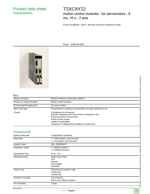
i s c l a i m er : T h i s d o c u m e n t a t i o n i s n o t i n t e n d e d a s a s u b s t i t u t e f o r a n d i s n o t t o b e u s e d f o r d e t e r m i n i n g s u i t a b i l i t y o r r e l i a b i l i t y o f t h e s e p r o d u c t s f o r s p e c i f i c u s e r a p p l i c a t i o n sProduct data sheetCharacteristicsTSXCAY22motion control modules - for servomotors - 8ms..10 s - 2 axisProduct availability : Stock - Normally stocked in distribution facilityPrice* : 5340.60 USDMainRange of productModicon Premium Automation platform Product or component type Motion control modules Product specific application For servo motorsServo loop type Proportional to overshoot compensation and gain switching 2 ms ChecksConsistency of commandsEncoder coupling, servo drive present, emergency stop Proper execution of movement Sensor power supply Validity of parametersPresence of voltage/sensor feedback counter inputComplementarySpeed profile path Trapezoidal or parabolic Resolution <= 1000 position units per point >= 0.5 position units per point Length of axis 256...32000000 P Acquisition speed >= 54000 points/mn <= 270000 points/mn Acceleration time 8 ms...10 s Operating modeDirect drive mode OFF ManualFOLLOWER AutomaticType of axisFollowing axis dynamic ratio Infinite axis Limited axisFunction of module Cut on the flyServo drive offset correction I/O modularity2 axesInput compatibility Absolute encoder SSI output 12...25 bitsIncremental encoder 10...30 V totem poleIncremental encoder 5 V DC RS422With 2-wire/3-wire sensor (24 DC) auxiliary inputAbsolute encoder parallel output ABE7CPA11Clock frequency200 kHz SSI absolute encoderIncremental encoder frequency x1500 kHzIncremental encoder frequency x 41000 kHz in counting250 kHz in inputPower dissipation in W7.2...11.5 WInput type Current sink auxiliary input conforming to EN/IEC 1131 Type 2Resistive counter inputResistive servo drive control input conforming to EN/IEC 1131 Type 1 Input logic PositiveInput voltage24 V 8 mA auxiliary input24 V 8 mA servo drive control input5 V 18 mA counter inputInput voltage limits<= 5.5 V counter input19...30 V auxiliary input19...30 V servo drive control inputVoltage state 1 guaranteed>= 11 V auxiliary input>= 11 V servo drive control input>= 2.4 V counter inputCurrent state 1 guaranteed>= 3.5 mA servo drive control input>= 3.7 mA counter input>= 6 mA auxiliary inputVoltage state 0 guaranteed<= 1.2 V counter input<= 5 V auxiliary input<= 5 V servo drive control inputCurrent state 0 guaranteed<= 1 mA counter input<= 1.5 mA servo drive control input<= 2 mA auxiliary inputInput impedance270 Ohm counter input3000 Ohm auxiliary input3000 Ohm servo drive control inputNumber of outputs 2 analogue output static2 reflex output static conforming to EN/IEC 611312 servo drive validation output relayAnalogue output range+/- 10...24 VAnalogue output resolution13 bits + signLSB value 1.25 mV analogue outputOutput voltage24 V DC reflex output24 V DC servo drive validation outputOutput voltage limits19...30 V reflex output5...30 V servo drive validation outputNominal output current0.5 A reflex outputMaximum output current 1.5 mA analogue output200 mA servo drive validation output625 mA reflex outputMinimum load 1 mA 1 VVoltage drop< 1 V at state on reflex outputLeakage current< 0.3 mA reflex outputSwitching time< 5 ms for servo drive validation< 500 µs for reflex outputOutput compatibility Positive logic DC inputs (resistance <= 15 kOhm) reflexShort-circuit protection Current limiter reflex outputThermal tripping reflex outputOutput overload protection Current limiter reflex outputThermal tripping reflex outputOutput overvoltage protection Zener diode between outputs and 24 DC reflex outputReverse polarity protection Reverse diode on supply reflex outputLocal signalling 2 LEDs green axis diagnostics available1 LED green module operating (RUN)1 LED red external fault (I/O)1 LED red internal fault, module failure (ERR)Electrical connection1 connector HE-10 20 pins for aux inputs, reflex output, for external sensor and preactuator power supply1 connector HE-10 20 pins for servo drive ctrl inputs + for ext power supply of servo drive inputs/outputs1 connector SUB-D 9 for an analogue output (speed reference)2 connectors SUB-D 15 for an incremental or absolute encoder Current consumption1100 mA 5 V DC 15 mA 24 V DC11...20 mA 24 V DC on 10/30 V absolute encoder module Module format StandardProduct weight1.06 lb(US) (0.48 kg)EnvironmentProtective treatmentTCAmbient air temperature for operation 32...140 °F (0...60 °C)Ambient air temperature for storage -13...158 °F (-25...70 °C)Relative humidity 5...95 % without condensation Operating altitude<= 6561.68 ft (2000 m)Ordering and shipping detailsCategory22558 - TSX PREMIUM, ATRIUM & PL7 PRO Discount Schedule PC22GTIN00785901123675Nbr. of units in pkg.1Package weight(Lbs) 2.21Returnability N Country of originFROffer SustainabilitySustainable offer status Not Green Premium productRoHS (date code: YYWW)Compliant - since 0806 - Schneider Electric declaration of conformity Schneider Electric declaration of conformity REAChReference not containing SVHC above the threshold Reference not containing SVHC above the threshold Product end of life instructionsNeed no specific recycling operationsContractual warrantyWarranty period18 monthsDimensions DrawingsStandard and Extendable Racks for Modules MountingDimensions of Modules and Racks(1) With screw terminal block modules.(2) Maximum depth for all types of modules and their associated connectors.Connection of Speed Reference Signals Connector PinoutConnection of Counting SignalsConnectors PinoutsConnection of Sensors/Pre-actuators and Encoder Power Supply, without Variable Speed ControllerHE10 Connector PinoutThe auxiliary inputs/outputs are allocated the following functions:●I0 = cam reference point input,●I1 =emergency stop input (stop if there is no current in the input),●I2 = adjusting input,●I3 = adjustment input,●Q0 = reflex output (static output),●0 V = shared auxiliary inputs and reflex outputs.Connection of the Variable Speed Controller Signals Connector PinoutThe axis command modules implement basic management of the signals necessary for correct operation of the variable speed controllers. Thereis only one connector, regardless of the number of axis command module channels.COMx – VALVARx: potential free contact to validate variable speed controller OK_VARx: variable speed controller input check 24 V – 0 V sensor power supplyNOTE: Each channel uses a potential free closing contact.。
科威自控运动控制器 HM系列参考手册说明书
黄石市科威自控有限公司资料编号:20210901-V14第一章安全注意事项 (1)第二章运动控制器选型 (3)2.1主要功能 (3)2.2型号说明 (4)第三章运动控制器安装与尺寸 (5)3.1运动控制器安装 (5)3.1.1安装场所 (5)3.1.2环境条件 (5)3.1.3安装方向与间隔 (5)3.2运动控制器尺寸 (6)第四章运动控制器接口 (7)4.1电源配线 (7)4.2状态识别 (8)4.3开关量输入 (8)4.4开关量输出 (9)第五章PLC 功能 (11)5.1软元件介绍 (11)5.1.1输入输出继电器[X],[Y] (12)5.1.2辅助继电器[M] (13)5.1.3状态继电器[S] (14)5.1.4定时器[T] (15)5.1.5计数器[C] (17)5.1.6数据寄存器[D] (22)5.1.7扩展寄存器[R] (24)5.1.8变址寄存器[V],[Z] (25)5.1.9标记指针[P],[I] (26)5.1.10常数[K],[H] (28)5.1.11掉电保护 (28)5.2基本逻辑指令 (28)5.2.1[LD],[LDI],[OUT]指令 (30)5.2.2[AND],[ANI]指令 (31)5.2.3[OR],[ORI]指令 (32)5.2.4[LDP],[LDF],[ANDP],[ANDF],[ORP],[ORF]指令 (33)5.2.5[ORB]指令 (34)5.2.6[ANB]指令 (35)5.2.7[MPS],[MRD],[MPP]指令 (36)5.2.8[MC],[MCR]指令 (39)5.2.9[INV]指令 (41)5.2.10[ALT]指令 (42)5.2.11[PLS],[PLF]指令 (43)目录5.2.13对应计数器软元件C的[OUT],[RST]指令 (45)5.2.14[NOP],[END]指令 (46)5.2.15编程注意事项 (47)5.3步进顺控指令 (48)5.3.1[STL],[RET]指令 (48)5.3.2分支与汇合 (49)5.3.3循环与跳转 (50)5.3.4步进指令应用示例 (50)5.4常规功能指令 (52)5.4.1条件跳转[CJ] (54)5.4.2子程序调用[CALL]/子程序返回[SRET] (56)5.4.3主程序结束[FEND] (57)5.4.4循环范围开始[FOR]/循环范围结束[NEXT] (58)5.4.5监视定时器[WDT] (60)5.4.6开始比较[LD□] (61)5.4.7并联比较[OR□] (62)5.4.8串联比较[AND□] (63)5.4.9数据比较[CMP] (64)5.4.10区域比较[ZCP] (65)5.4.11传送[MOV] (66)5.4.12成批传送[BMOV] (68)5.4.13多点传送[FMOV] (70)5.4.14高低字节交换[SWAP] (72)5.4.15两个数据交换[XCH] (73)5.4.16批次复位[ZRST] (74)5.4.17反向传送[CML] (76)5.4.18加法[ADD] (77)5.4.19减法[SUB] (78)5.4.20乘法[MUL] (79)5.4.21除法[DIV] (80)5.4.22加1[INC],减1[DEC] (82)5.4.23求平均值[MEAN] (83)5.4.24逻辑与[WAND],逻辑或[WOR],逻辑异或[WXOR] (84)5.4.25求负[NEG] (87)5.4.26开方[SQR] (89)5.4.27循环左移[ROL],循环右移[ROR] (90)5.4.28带进位循环左移[RCL],带进位循环右移[RCR] (92)5.4.29位左移[SFTL],位右移[SFTR] (94)5.4.30字左移[WSFL],字右移[WSFR] (96)5.4.31移位读出[SFRD] (99)5.4.32移位写入[SFWR] (100)5.4.33整型转浮点[FLT] (101)5.4.34浮点转整型[INT] (102)5.4.36二进制转BCD[BCD] (104)5.4.37十六进制转ASCII[ASCI] (105)5.4.38ASCII转十六进制[HEX] (106)5.4.39浮点比较[ECMP] (107)5.4.40浮点区域比较[EZCP] (108)5.4.41浮点加法[EADD] (109)5.4.42浮点减法[ESUB] (110)5.4.43浮点乘法[EMUL] (111)5.4.44浮点除法[EDIV] (112)5.4.45浮点十进制转浮点二进制[EBIN] (113)5.4.46浮点二进制转浮点十进制[EBCD] (114)5.4.47浮点开方[ESQR] (116)5.4.48浮点SIN运算[SIN] (117)5.4.49浮点COS运算[COS] (118)5.4.50浮点TAN运算[TAN] (119)5.4.51浮点ASIN运算[ASIN] (120)5.4.52浮点ACOS运算[ACOS] (121)5.4.53浮点ATAN运算[ATAN] (122)5.4.54浮点RAD运算[RAD] (123)5.4.55浮点DEG运算[DEG] (124)5.4.56输入输出刷新[REF] (125)5.4.57PID控制[PID] (127)5.5中断系统 (130)5.5.1中断资源介绍 (130)5.5.2中断执行流程 (130)5.5.3中断指令[EI],[IRET],[DI] (132)5.5.4中断嵌套 (133)5.5.5定时器中断 (134)5.5.6外部输入中断 (135)5.5.7系统软中断 (136)5.5.8高级中断 (137)5.6虚拟示波器 (141)5.6.1触发方式 (141)5.6.2触发单元 (142)5.6.3触发门限 (142)5.6.4采样周期 (142)5.6.5采样点数 (142)5.6.6记录起始寄存器序号 (143)5.6.7记录区间起始寄存器序号 (144)5.6.8记录区间终止寄存器序号 (144)5.6.9示波器状态设置/显示 (145)5.6.10当前采样点 (145)5.6.11通道工作模式 (145)5.7特殊辅助继电器[M],特殊数据寄存器[D] (147)5.7.1特殊辅助继电器[M]功能一览表 (147)5.7.2特殊辅助寄存器[D]功能一览表 (154)第六章通信功能 (161)6.1通信原理 (161)6.1.1通信方式 (161)6.1.2网络系统结构 (162)6.2串口初始化[UINIT] (164)6.3计算机链接协议 (166)6.3.1通信格式 (166)6.3.2任务调度配置 (169)6.3.3通信示例 (171)6.4MODBUS协议 (173)6.4.1通信格式 (173)6.4.2软元件通信地址 (174)6.4.3MODBUS指令 (174)6.4.4通信示例 (184)6.5自由协议 (185)6.5.1任务调度配置 (185)6.5.2自由协议指令 (187)6.5.3通信示例 (189)6.6其他协议 (191)第七章扩展模块 (192)7.1扩展寄存器 (192)7.2模拟量模块 (193)7.2.1模块规格 (193)7.2.2模块读写控制 (195)7.2.3输入模拟量 (196)7.2.4输出模拟量 (196)7.3开关量模块 (198)7.3.1模块规格 (198)7.3.2模块读写控制 (200)第八章运动控制 (201)8.1运动控制指令 (201)8.2运动轴对象 (202)8.2.1运动轴定义 (202)8.2.2运动输入轴参数配置 (203)8.2.3运动输出轴参数配置 (204)8.3单轴基本运动 (217)8.3.1回原点[HOME] (218)8.3.2点动[JOG] (221)8.3.3定位[PSOUT] (225)8.3.4制表[PTAB] (227)8.3.6插补[IPL] (238)8.3.7定速定长输出[DPLSY] (240)8.3.8加减速定长输出[DPLSR] (242)8.3.9相对定位[DDRVI] (244)8.3.10绝对定位[DDRVA] (246)8.3.11中断定位[DDVIT] (248)8.3.12变速输出[DPLSV] (250)8.3.13高速读出[DHMOV] (252)8.3.14高速比较置位[DHSCS] (253)8.3.15高速比较复位[DHSCR] (255)8.3.16高速区间比较[DHSZ] (257)8.3.17高速表格比较输出[DHSCT] (259)8.4单轴关联运动 (261)8.4.1电子齿轮[GEAR] (261)8.4.2电子凸轮[CAM] (264)8.4.3追剪正程/滚切制表[PCTAB] (283)8.4.4追剪返程制表[PBTAB] (289)安全警告和标识第一章安全注意事项警告标识含义该标识表示若操作错误则可能发生“死亡或重伤”该标识表示若操作错误则可能发生“人身伤害或财产损害”安全标识含义该图形表示“不可实施”的内容该图形表示“必须实施”的内容切勿在有水的地方、存在腐蚀性、引火性气体的环境内以及可燃物旁使用,容易发生火灾不要在振动和冲击激烈的地方使用不要用湿手进行接线和设备操作切勿将手伸入运动控制器内部不要使导线受到损伤或承受过大的外力、重压、受夹切勿用裸手检查伺服接线故障,容易引发触电应在尘埃较少,不会接触到油、水的地方放置请进行正确的接线,否则可能发生火灾或故障导线应连接好,通电部位须通过绝缘套做到绝缘运动控制器必须实际接地外部应设置紧急停止电路,以确保紧急时可及时地停止运转、切断电源运动控制器的移动、接线、检查等要在切断电源并确保放电结束后没有触电危险的前提下进行必须设置过电流保护装置、漏电断路器、温度防护装置以及紧急停止装置安全注意事项不要在运动控制器上放置重物不要使运动控制器受到较强的冲击不要频繁地开、关主电源不要对运动控制器进行长时间极限情况测试切勿自行改造、分解、修理严格按照正确的安装方法安装运动控制器确保运动控制器在规定的温度和湿度范围内运行发生故障时请清除故障、确保安全后再重新运行运动控制器发生故障时请切断电源第二章运动控制器选型2.1主要功能●掉电数据保存掉电保存数据功能,运动控制器可以在断电时自动保存用户数据。
昆腾PLC 运动模块 使用手册

Modicon Quantum Automation Series MSx Motion Module Reference Guide840 USE 105 00 Version 3.0February , 1996AEG Schneider Automation, Inc. One High Street North Andover , MA 01845PrefaceThe data and illustrations found in this book are not binding. We reserve the right to modify our products in line with our policy of continuous product development. The information in this document is subject to change without notice and should not be construed as a commitment by AEG Schneider Automation, Inc. AEG Schneider Automation assumes no responsibility for any errors that may appear in this document. If you have any suggestions for improvements or amendments or have found errors in this publication, please notify us by using the form on the last page of this publication. No part of this document may be reproduced in any form or by any means, electronic or mechanical, including photocopying, without express written permission of the Publisher, AEG Schneider Automation, Inc.Caution: All pertinent state, regional, and local safety regulations must be observed when installing and using this product. For reasons of safety and to assure compliance with documented system data, repairs to components should be performed only by the manufacturer .MODSOFTâ is a registered trademark of AEG Schneider Automation, Inc. The following are trademarks of AEG Schneider Automation, Inc.: Modicon Modbus Plus Modbus II Compact 984 PLC P230 Quantum Automation Series Modbus 984 Modicon Micro PLC P190DIGITALâandDECâareregisteredtrademarksofDigitalEquipment Corporation. IBMâ and IBM ATâ are registered trademarks of International Business Machines Corporation. Microsoftâ and MS DOSâ are registered trademarks of Microsoft Corporation. ã Copyright 1995, AEG Schneider Automation, Inc. Printed in U.S.A.840 USE 105 00PrefaceiiiContentsChapter 1 Overview .................................................. 1.1 Related Publications . . . . . . . . . . . . . . . . . . . . . . . . . . . . . . . . . . . . . . . . . . . .1 2Chapter 2 Specifications 2.1and HardwareOverview......................3 4 6 7 9 11 13 152.2MSx Motion Modules . . . . . . . . . . . . . . . . . . . . . . . . . . . . . . . . . . . . . . . . . . . 2.1.1 Front Panel Indicators . . . . . . . . . . . . . . . . . . . . . . . . . . . . . . . 2.1.2 Front Panel Connectors . . . . . . . . . . . . . . . . . . . . . . . . . . . . . . 2.1.3 Rear Panel Switches . . . . . . . . . . . . . . . . . . . . . . . . . . . . . . . . . 2.1.1 Operational Specifications . . . . . . . . . . . . . . . . . . . . . . . . . . . 2.1.2 Electrical Specifications . . . . . . . . . . . . . . . . . . . . . . . . . . . . . Breakout Module . . . . . . . . . . . . . . . . . . . . . . . . . . . . . . . . . . . . . . . . . . . . . . .Chapter 3 System Information 3.1 3.2 3.3.........................................17 18 19 20Flash Memory . . . . . . . . . . . . . . . . . . . . . . . . . . . . . . . . . . . . . . . . . . . . . . . . . Communications Protocol . . . . . . . . . . . . . . . . . . . . . . . . . . . . . . . . . . . . . . . On-line and Off-line Development with MMDS . . . . . . . . . . . . . . . . . . . .Appendix A Parts List . . . . . . . . . . . . . . . . . . . . . . . . . . . . . . . . . . . . . . . . . . . . . . . . . . Appendix Hardware B.1 B Installation21.......................................23 24 27 31Mounting and Connecting the MSx Modules . . . . . . . . . . . . . . . . . . . . . . B.1.1 Motion Cables . . . . . . . . . . . . . . . . . . . . . . . . . . . . . . . . . . . . . . ......................................................Index840 USE 105 00ContentsvviContents840 USE 105 00Chapter 1 OverviewThe Quantum Automation Series single axis motion (MSx) modules (140 MSB 101 00 and 140 MSC 101 00) are designed to control a single axis of motion using advanced digital brushless motion control. This capability provides optimal control by eliminating potentiometer adjustments and analog velocity loops. The MSx modules are designed to interface directly to the Modicon Cyberline 1000 series brushless servo amplifiers as well as other types of dc and brushless drives.Note:These modules are designed to serve your many and varied applications with great accuracy and speed. However, certain applications might be outside the scope of this module. Please consult Modicon for applications information if you intend to use the module specifically for precise velocity control. The primary feedback used by the direct numeric processing (DNP) servo system is position information from either a resolver or an encoder mounted to the motor. Velocity information is derived from the position information, rather than being received from a velocity transducer. This leads to some inaccuracies when using the DNP servo as a velocity controller. Small speed irregularities may result, particularly at slower speeds. If a CL1000D drive is used, this will probably not be an issue as the CL1000D drive uses software techniques that give the overall system good velocity regulation.Note:840 USE 105 00Overview11.1RelatedPublicationsIn addition to this manual, you will need: V VSingle Modicon Axis Software Motion System (SASS) Motion User Guide User GuideDevelopmentSoftware(MMDS)The Single Axis Software System (SASS) Motion User Guide provides a comprehensive description of Modicon single-axis motion control systems and important system design and performance information. It also presents the SASS programming language, including instructions for setting up and configuring your applications. The Modicon Motion Development Software (MMDS) User Guide presents basic instructions for installing, initializing, and using this intuitive, interactive, menu-driven tool. MMDS helps you create, test, debug, and maintain your application programs. Other related documents include: V V VCyberline Cyberline Quantum 1000A 1000D System Design and Installation ManualDrive User Guide Series Hardware Reference GuideAutomation2Overview840 USE 105 00Chapter 2 Specifications Overviewand HardwareV VMSx Motion Modules Breakout Module840 USE 105 00Specificationsand HardwareOverview32.1MSx MotionModulesThe Quantum single axis motion (MSx) modules are incremental encoder (140 MSB 101 00) or resolver and encoder (140 MSC 101 00) feedback-only modules contained in a single-width housing. It works with servo motors that use Cyberline drives and other types of DC and brushless drives from other manufacturers. The illustration below shows a typical configuration of a single axis motion control system.MMDS on PC or Compatible Quantum CPU Modbus (for programming)Quantum BackplaneMSx ModuleBreakout ModuleAnalog I/OAdditional Discrete I/ODriveMotor FeedbackLimitsLimitsMotor Load4Specificationsand HardwareOverview840 USE 105 00The modules contain I/O to interface to the drive and the machine, including drive enable, drive fault, and a variety of user-configurable signals. The modules also include a high speed input pin to perform high speed position capture. See below for an illustration of the Quantum MSx module.MSx modules are only installed in Quantum backplanes. Refer to the Quantum Automation Series Hardware Reference Guide (840 USE 100 00) for detailed specifications of all Quantum modules and associated hardware.Note:840 USE 105 00Specificationsand HardwareOverview52.1.1Front Panel IndicatorsThere are seventeen LED indicators visible on the front panel:140 MCX 101 00 LED IndicatorsLEDs Active Ready + Lim ok Lim ok Active Ready +Lim ok Lim ok Home In 4 In 5 In 6 In 7 Drv Flt Drv En Out 1 Out 2 Out 3 Modbus Moving In Pos Home In 4 In 5 In 6 In 7 Drv Flt Drv En Out 1 Out 2 Out 3 Modbus Moving In Pos Color Green Green Green Green Green Green Green Green Green Red Green Green Green Green Green Amber Amberand DescriptionsIndication when On Bus communication is present. The module has passed powerup diagnostics. Digital Input 1 active. Digital Input 2 active. Digital Input 3 active. Digital Input 4 active. Digital Input 5 active. Digital Input 6 active. Digital Input 7 active. Fault signal from drive. Drive enabled. Digital Output 1 active. Digital Output 2 active. Digital Output 3 active. Communications are active on the Modbus port. Motor is moving. Motion is within the in position of the final target.6Specificationsand HardwareOverview840 USE 105 00Specifications and Hardware Overview 840USE 1050072.1.2Front Panel ConnectorsThere are two connectors located on the front of the module:ModbusConnectorThe MSx modules are equipped with a 9—pin RS 232C connector that supports Modicon’s proprietary Modbus communication protocol.The following is the Modbus port pinout connections for 9—pin and 25—pin connections.Signal MSx Pin Signal Function 112No Connection3TXD RXD 32RXD TXD 55GND GND 77RTS RTS 88CTSCTSShieldSerial data Serial data Ground Control line Control lineMSx ModbusPort Pinoutsto 9—PinConnectors(AS W956xxx)46DTR DSR 64DSR DTR Control line Control line ComputerPinSignal MSx Pin ComputerPinSignal Function 112No Connection2TXD RXD 33RXD TXD 57GND GND 74RTS RTS 85CTSCTSShieldSerial data Serial data Ground Control line Control lineMSxModbus Port Pinouts for 25—Pin Connectors (AS W955xxx)46DTR DSR 620DSR DTR Control line Control lineSpecificationsand HardwareOverview840USE 105008Servo ConnectorThe MSx is also equipped with a 50—pin servo connector for communication with feedback devices.Note:The tables below show the 50pin servo connector signals.Pinnumbers correspond to both the MSB and MSC modules.When the signals differ from each other,they are shown separated by a slash (i.e.,Pin Number 34,MSB/MSC).Servo Connector Signals (from left to right)5034N /CN /C /R e f e r e n c e O u t p u t L o wN /C /R e f e r e n c e O u t p u t H i g hN /C /S i n e I n p u t L o wN /C /S i n e I n p u t H i g hN /C /C o s i n e I n p u t L o wN /C /C o s i n e I n p u t H i g hO v e r t e m p L o wO v e r t e m p H i g hD r i v eE n a b l e C o m m o nD r i v eE n a b l e C o n t a c t (N C )D r i v eE n a b l e C o n t a c t (N O )D r i v e F a u l tV e l o c i t y/P h a s e C o m m o nN /C /P h a s e CN /C /P h a s e BV e l o c i t y +/P h a s e A5049484746454443424140393837363534Servo Connector Signals (from left to right)3318Servo Connector Signals (from left to right)171N /C (N o t C o n n e c t e d )N /CN /CN /CN /CE n c o d e r 2M a r kE n c o d e r 2M a r k +E n c o d e r 2P h a s e BE n c o d e r 2P h a s e B +E n c o d e r 2P h a s e A E n c o d e r 2P h a s e A +E n c o d e r 1M a r kE n c o d e r 1M a r k +E n c o d e r 1P h a s e BE n c o d e r 1P h a s e B +E n c o d e r 1P h a s e AE n c o d e r 1P h a s e A +17161514131211109876543212.1.3Rear Panel SwitchesThe MSx has an RS-232serial port to connect the module to an IBMPC(or compatible)running the Modicon Motion Development Software(MMDS).A two-position DIP switch is located on the rear panel of themodule(below).SW1is used to specify the module’s operating mode(984or MMDS control).SW2is used to specify the communicationpower-up.characteristics of the Modbus port uponSpecifications and Hardware Overview840USE105009Specifications and Hardware Overview840USE 1050010 4.When the Set Local Lockout command is not issued and both the Compact 984and MMDS are communicating to the module,the setting of SW1controls which device has write privilege.Note:Either device may read—that is,issue a GET command—atany time.However,reading the error log (a system command)is not allowed without write privilege because the log is lost once it has been read.See the Single Axis Software System (SASS)Motion User Guide for details.2.1.3.2Setting Modbus Comm Characteristics with SW2The SW2setting determines the Modbus communicationcharacteristics.When the module is powered up,SW2is read.When the switch is closed,the default characteristics are used.When theswitch is open then the communication characteristics last saved in the module are used.Once communication characteristics are initialized,they may bechanged at any time under software control only if SW2is in the open position.See the Single Axis Software System (SASS)Motion User Guide for details.When SW2is closed,these Modbus port default characteristics are used:V One start bit V Seven data bits V One stop bitV Even parity checking V9600baudSpecifications and Hardware Overview 840USE 10500112.1.1OperationalSpecificationsServoCommutation Update Rate 0.25ms Velocity Loop Update Rate 0.5ms Velocity Loop Bandwidth >100Hz Velocity Range6000rpm Position Loop Update rate 1msPosition Accuracy Resolver+10arc minutes typical,+15arc minutes max Position RepeatabilityResolver +5arc minutes maxPosition AccuracyEncoderEncoder dependent,0.5arc minutes maxCommunicationProtocolModbus Address (set by software)1default Baud Rate (set by software)30019200baud,9600defaultApplicationProgramExecution Rate See note below Storage650instructionsNote:A majority of the instructions typically take 1ms to execute.The execution time of an instruction,though,is not constant.The execution time can increase due to factors such as:if the Sync Ratio Mode is on,how often the position generator must execute to plan out new moves,how many whenevers are enabled,the number of sources requesting commands be executed (e.g.,backplane,internal program,Modbus port),etc.If timing is extremely critical to an application,actual time must be determined experimentally by running the actual application program.High Speed InputPosition Capture Time 250s max Isolation 500V to system bus Pulse Width25s Minimum Time Between Successive Captures20msDiscreteInputsNumber 7Scan Time 1.5msIsolation500V to system busSpecifications and Hardware Overview840USE 1050012Discrete OutputsNumber 3Update Time 10ms maxIsolation 500V to system bus Reset State 0V,nominal On State 24V,nominalOutput Type Totem pole (sink/source)Protection Short circuit,overvoltage FaultOvercurrent detectedAnalogInputNumber 1Scan Time 15msData User configurable Range +10VAccuracy+100mV,plus offsetAnalogOutputNumber 1Scan Time 20msData User configuable Range +10VAccuracy+50mV,plus offsetResolverFeedback(Fully ConfiguredVersion)Conversion Method Tracking Resolver Style Transmit Excitation Frequency 5kHzExcitation Amplitude Automatically adjusted Excitation Current 120mALoss of FeedbackDetected within 40msIncrementalEncoderFeedbackResolution 4times line count SignalsA,B,MarkSignal Frequency 200kHz,up to 500kHz with reduced noise immunity Encoder Output style Differential,5V Loss of FeedbackDetected within 40ms2.1.2Electrical SpecificationsDiscrete Inputs and High Speed InputInput Impedance 3.5kInputs On15Vdc minInputs Off5Vdc maxIsolation500Vac to system busDiscrete OutputDrive Capability150mA at user supplied19.2...30VdcresistiveProtection Current limit,thermalIsolation500Vac to system busAnalog InputResolution10bitsInput Impedance30kOffset+50mVAccuracy+100mV,plus offsetAnalog OutputResolution12bitsDrive Capability3mAOffset+50mVAccuracy+50mV,plus offsetResolver InterfaceReference5+0.05kHz,1.6...5.5V rms50mA drive capabilitySine/Cosine Input Impedance3kResolution16bits to300rpm14bits to1350rpm12bits to6000rpmAccuracy10arc minutes,typical,resolver dependentMotor Temperature InputNormal State Short circuit,2mA sink maxFault State Open circuitIsolation500Vac to system busSpecifications and Hardware Overview840USE1050013Specifications and Hardware Overview840USE 1050014Encoder Feedback InterfaceInput Range 0.7...7Vdc Input Impedance 145,nominal Differential Signals,High +2V differential,min Differential Signals,Low 2V differential,minMaximum Encoder Frequency 200kHz square wave(55%...45%with less than 15_of quadrature error)Isolation500Vac to system bus with external power supply Minimum Encoder Pulse Width1msDrive InterfaceDrive Fault Input True high,TTL compatible relative to remote common,10K internal pull up resistor Drive Enable RelayForm C contacts120Vac @0.1A resistive 30Vdc @0.5A resistive Current Command Voltages+10Vdc Current Command Summing Accuracy 0+0.1VdcCurrent Commands3mA drive capabilityPower RequirementsMain Power Input 5V +5%@750mA(with no encoders or resolvers attached,output off)Main Power Input 5V +5%@1000mA(with maximum encoder and resolver load,outputs on)Hot Swap Surge CurrentLess than 5ASpecifications and Hardware Overview 840USE 10500152.2Breakout ModuleThe Breakout Module (see below)is the I/O wiring block connector for the 140MSx 10100Single Axis Motion Module servo connections.It is connected to the MSx via a Breakout Module cable (690MCI 000xx)at the 50pin servo connector.Refer to the previous section for a description of the servo connectorsignals.Note:Provided with the Breakout Module are labels for the MSBand MSC modules (see Appendix B).These labels are a reference for the Breakout Module signal names.Attach the applicable label near this Breakout Module in your cabinet orrack.Specifications and Hardware Overview840USE 1050016A Breakout Module cover (below),Modicon #690MCB 10100,is also available,which shields the termination points of the breakout module from electrostatic discharge.It is a metal plate that is screwed down to the same panel as the DIN rail that holds the Breakout Module.This cover is required to make the system CE *compliant (refer to Appendix B for installationinstructions).*The CE mark indicates compliance with the European Directive on Electromagnetic Compatibility (EMC)(89/336/EEC).In order to maintain compliance,the Quantum system must be installed per the installation instructions.Chapter 3 System InformationV V VFlash Memory Communications Protocol On-line and Off-line Development with MMDS Refer to Appendix E in the Single Axis Software System User Guide for system checkout information.Note: (SASS)Motion840 USE 105 00SystemInformation173.1Flash MemoryThe MSx comes with a flash EEPROM that allows storage of application programs and configuration parameters such as servo parameters, speed limits, etc. The flash also accepts firmware updates as firmware enhancements become available.18SystemInformation840 USE 105 003.2CommunicationsProtocolBackplane communications with the MSx is through six 3x and 4x registers, which must be I/O mapped to the MSx. Modbus communication with the MSx is through six pairs of registers via the Modbus communication link. The register format is very rigid. The first register sent to the module (4X)is always the control register, and the second is always the command register. The first register returned from the module (3X) is always the current status of the module, while the second register returned is always an echo of the command register. All remaining registers, data register 1 ... 4, are reserved for data and are used as necessary. For additional information refer to Single Axis Software System (SASS) Motion User Guide .840 USE 105 00SystemInformation193.3On-line MMDSand Off-lineDevelopmentwithThe Modicon Motion Development Software (MMDS), Version 4.1 or higher, is an on-line/off-line software package which runs on a user-supplied IBM PC or compatible computer. MMDS is purchased separately. The computer with MMDS can be connected to the MSx through an RS-232 serial interface. With MMDS, you can set parameters, check module diagnostics, and exercise the motor during initial system setup. You can also write motion programs and download them into the MSx directly.Note: If the module is I/O mapped in a Quantum PLC and the user has a Modbus Plus adaptor card in their PC, it is possible to do on line development over the Modbus Plus network. Refer to the Modicon Motion Development Software (MMDS) User Guide for details.20SystemInformation840 USE 105 00Appendix A Parts ListPart NumberDescription140 MSB 101 00 140 MSC 101 00 690 MCB 000 00 690 MCB 101 00 690 MCI 000 01 690 MCI 000 03 690 MCI 000 06Quantum Motion Module Quantum Motion Module Breakout Module, 50 Signal CE Compliant Breakout Module Cover Low profile DB50/DB50 cable, 1 ft Low profile DB50/DB50 cable, 3 ft Low profile DB50/DB50 cable, 6 ft840 USE 105 00Parts List21A.122Parts List840 USE 105 00Appendix HardwareB InstallationVMounting and Connecting the MSx Modules840 USE 105 00HardwareInstallation23B.1Mounting Modulesand Connectingthe MSxThe MSx modules can be inserted into any slot of any backplane and removed under power (hot swapped) without damaging modules or the backplane (Quantum power supply modules must be installed in the first or last slots of the backplane). Refer to the following figures and procedure when mounting modules.Note:For the required grounding configurations for the single axis motion modules, refer to Appendix D of the Quantum Automation Series Hardware Reference Guide .1 2Select a Quantum backplane. Remove the backplane connector cover(s).Backplanes are designed to mechanically secure and electrically connect all modules used in drops. The backplane contains a passive circuit board which permits modules to communicate with each other and to identify their slot numbers without further switch settings.Note:To meet vibration/shock specifications, the backplane must be mounted using all specified mounting holes. The backplane is mounted using standard hardware (described below). The recommended length for the mounting screws should be within the following range: 0.24 in (6 mm) 0.52 in (13 mm )The head height of the screws should not exceed 0.14 in (3.5 mm).24HardwareInstallation840 USE 105 00Hook3Backplane ConnectorMount the MSx at an angle on to the two hooks located near the top of the backplane. Swing the MSx down to make an electrical connection with the backplane I/O bus connector. Tighten the screw at the bottom of the MSx to fasten it to the backplane.The maximum tightening torque for these screws is 2 4 in lbs.4MSx Module5BackplaneMSx Servo Connector6Once installed, connect the MSx, using a 690 MCI 000 0x breakout cable to the breakout module as follows. Reverse the order of these steps to remove breakout cable.a.690 MCI 000 0x CableAs shown in this illustration, line up the connector on the MSx and push the cable firmly into the connector. Once the cable is secured to the connector, tighten the screws onto the connector. Plug the other end of the cable into the breakout module using the same procedure as above.b.c.MSx Breakout Module840 USE 105 00HardwareInstallation257When installing a system that must meet the European CE* Approval Standards, the following special wiring techniques are required:a.The Breakout Module Cover (Modicon # 690 MCB 101 00) must be installed over the Breakout Module after field wiring has been completed in order to shield the termination points from electrostatic discharge. The cover should be placed over the Breakout Module so as to completely cover the terminals and should be screwed down on the same panel as the DIN rail that supports the Breakout Module. If the analog input is used, the twisted shielded pair (Belden 8451, Alpha 2462, or equivalent) for the analog input signal should be stripped about 12 inches back from the Breakout Module to expose the shield. The exposed shield should then be attached to the grounded mounting panel using a Grounding Cable Rail (Modicon # 043509693). In addition, two ferrite beads (Steward # 2880686 200 or equivalent) should be placed over the analog input cable between the grounding cable rail and the Breakout Module.b.c.d. e.bBreakout Module DIN Railcae dPanel Breakout Module Cover*The CE mark indicates compliance with the European Directive on Electromagnetic Compatibility (EMC) (89/336/EEC). In order to maintain compliance, the Quantum system must be installed per the installation instructions.840 USE 105 0026HardwareInstallationHardware Installation 840USE 1050027d.Apply the applicable label (MSB or MSC shown below)to the cabinet or rack as a reference for breakout module connection names.Modicon 140MSB 10100Connections 1CH2A+1824VDC 34VEL+2CH2A 1924Com 35N/C 3CH2B+20Brake 36N/C 4CH2B 21OUT 237VEL 5CH2M +22OUT 338Drv Flt 6CH2M 23CW Lim 39EN NO 7CH3A+24CCW Lim 40EN NC 8CH3A 25Home 41EN Com 9CH3B+26IN 442OTemp +10CH3B 27IN 543OTemp 11CH3M+28IN 644N/C 12CH3M 29IN 745N/C 13N/C 30HSI 46N/C 14N/C 31AN OUT 47N/C 15N/C 32AN Com 48N/C 16N/C 33AN IN 49N/C 17N/C 50N/C Modicon 140MSC 10100Connections 1CH2A+1824VDC 34ØA 2CH2A 1924Com 35ØB 3CH2B+20Brake 36ØC 4CH2B 21OUT 237ØCOM 5CH2M +22OUT 338Drv Flt 6CH2M 23CW Lim 39EN NO 7CH3A+24CCW Lim 40EN NC 8CH3A 25Home 41EN Com 9CH3B+26IN 442OTemp +10CH3B 27IN 543OTemp 11CH3M+28IN 644COS+12CH3M 29IN 745COS 13N/C 30HSI 46SIN+14N/C 31AN OUT 47SIN 15N/C 32AN Com 48REF+16N/C 33AN IN 49REF 17N/C 50N/CHardware Installation 28840USE 10500B.1.1Motion CablesThese tables include signal,pin,and wire information for the AS W9200XX and AS W9220XX module cables.AS W9200XX Cable (for connection to the DB25connector on CL1000A drives)Signal QMOT Breakout/Pin #W ire Color W920W ire Number CL1000A Connector Phase A 34Black 38Phase B 35White 19Phase C 36Blue 210Phase Com 37Orange 414Fault 38Yellow 822Enable N/O 39Green 520Enable Com 41Brown 615Shield Ground *Gray 9Shield AS W9220XX Cable (for the encoder signal from CL1000D drives)Signal QMOT Breakout/Pin #Ch.2Ch.3W ire Color W922W ire Number CL1000D Connector A+17White 22A 28Brown 77B+39Blue 33B 410Green 88M+511Orange 44M 612Violet 99Shield Ground *Bare Shield Shield Not Connected Black 11Not Connected Yellow 55Not Connected Red 66Not Connected Gray 1010*Refer to the breakout module diagram in Section 2.2.Hardware Installation 840USE 1050029Breakout Feedback Cables This table includes the signal,pin,and wire information for the 120169xx,120125xx,and the 120063xx resolver signal cables.These cables carry the resolver signal back to the breakout module from the motor.Signal MCx Pin Letter Designation 120169xx 120125xx 120063xx Reference +48O White White White Reference Com 49G Black Black Black Sine +46E Red Red Red Sine Com 47F Black Black Black Cosine +44I Green Green Green Cosine Com 45H Black Black Black Thermal High 42D Blue Black Red Thermal Low 43J Black Orange Green Brake High 20P Yellow Green Orange Brake Low 19N Black Red Black These cables are designated for dual resolvers,and as such,will have several wires not terminated when used with the MSx modules.This table includes the signal,pin,and wire information for the MC SSXX xx and MC TSXX xx cables.Signal MCx Pin Letter Designation SSXX TSXX Reference +48O White White Reference Com 49G Black Black Sine +46E Red Red Sine Com 47F Black Black Cosine +44I Green Green Cosine Com 45H Black Black Thermal High 42D Blue Black Thermal Low 43J Black Orange Brake High 20P Yellow Green Brake Low 19N Black Red。
- 1、下载文档前请自行甄别文档内容的完整性,平台不提供额外的编辑、内容补充、找答案等附加服务。
- 2、"仅部分预览"的文档,不可在线预览部分如存在完整性等问题,可反馈申请退款(可完整预览的文档不适用该条件!)。
- 3、如文档侵犯您的权益,请联系客服反馈,我们会尽快为您处理(人工客服工作时间:9:00-18:30)。
多功能运动控制模块说明书
1 .多功能运动控制模块系统介绍
多功能运动控制模块系统是三轮驱动结构机器人,三个驱动轮平均分布在底盘。
主体结构可分为三层板结构,底层板装配有驱动电机、驱动控制板、气源系统、执行气缸、电池等其他辅助部件;中层板包含盘球电机驱动控制板、控制电磁阀、电源控制板、调压阀;上层板部分主要用来安放笔记本和整个视觉系统的结构。
本多功能运动控制模块可用作各级别足球机器人的比赛,也可用作高校进行图像和视觉及自主避障等方面的研究平台。
图1多功能运动控制模块结构图
视觉系统
2 .多功能运动控制模块结构
多功能运动控制模块的底盘部分由3个电机和3个公司自主研发的全向轮组合构成,3个电机成120°平均分布在底层板上如图3所示,此机构可使机器人进行任意方向的前进运动,分别由三个驱动控制器来控制。
底层板部分包括2组锂电池可提供一个小时以上的开机运行时间,2个铝制气瓶、盘球系统、踢球机构。
(如图2所示)
图2 底层板结构示意图
踢球机构
图3 底层板电机分布结构图
多功能运动控制模块使用三只由上海埃依琪实业有限公司生产的36SYK71型功率163W 的空心杯转子直流碳刷电机。
该型电机采用高磁能积的稀土钕铁硼磁钢、专利的空芯杯转子、石墨电刷、CLL (电容熄弧长寿命)技术,具有体积小、效率高、惯量低、寿命长的优势,并具有无齿槽效应、加速性能高、电磁干扰小、线性的电压/速度曲线、线性的负载/速度曲线、线性的负载/电流曲线、转矩波动小、可短时过载、结构紧凑的技术特点。
电机数据见下表:
表1电机参数表
为获得更大的转矩和相对较合适的速度,MT-AGV小车动力系统中使用了三只埃依琪公司生产的P36HA型行星齿轮减速箱与36SYK71型直流电机配套。
该型减速箱为2级行星齿轮减速箱,具有传递转矩大、性能高、尺寸小、输入齿轮与输出齿轮同轴的特点。
P36HA减速箱特性参数见下表:
表2减速器参数表
多功能运动控制模块的中层板结构包括盘球电机控制系统(驱动控制器)、气源调节控制系统(调压阀、电磁控制阀)、其他控制电路板等(如图4所示)。
图4 多功能运动控制模块中层板结构图
多功能运动控制模块上层板部分包括控制开关、充电插头、IBM 笔记本、急停开关、全景视觉系统,底板与主体相连。
图5 MT-AGV
小车上层结构图
主体外壳体是薄板钣金折弯成型,分为左侧板1、左侧板2、右侧板1、右侧板2、后板五块组成(如图6所示),他们都采用魔术胶带固定到车身,这样便于机器人的观察和维修。
机械安装说明
全景摄像机组件拆装
拧掉全景支架底部的固定螺钉,可以把全景摄像机组件整体拆除。
外罩拆装
拧掉外罩两侧的固定螺钉,可以把两个侧罩和一个后罩拆除。
去掉所有外罩。
上层结构拆装
拧掉上层板边缘的12个螺钉,可以把上层结构整体拆除。
(可以在不拆全景
组件的情况下,整体拆除上层结构。
)
中层结构拆装
拧掉中层板四角的6个固定螺钉,拔开上下层间的线缆插头,可以把中下层结构整体分开。
这样可以对中、下层的电器进行检查维修。