PDMS11.6管道应力分析接口用户指南
PDMS破解必看-安装说明
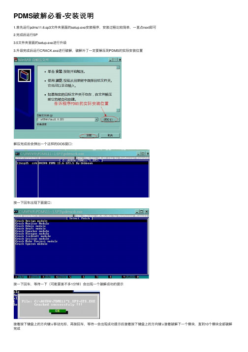
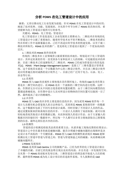
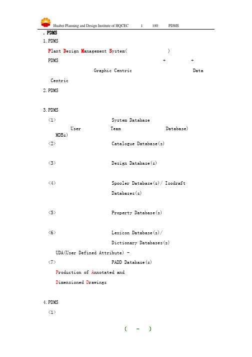
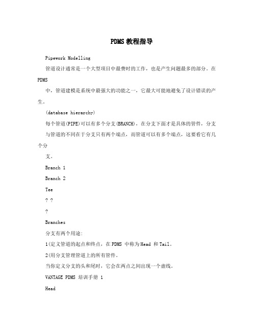
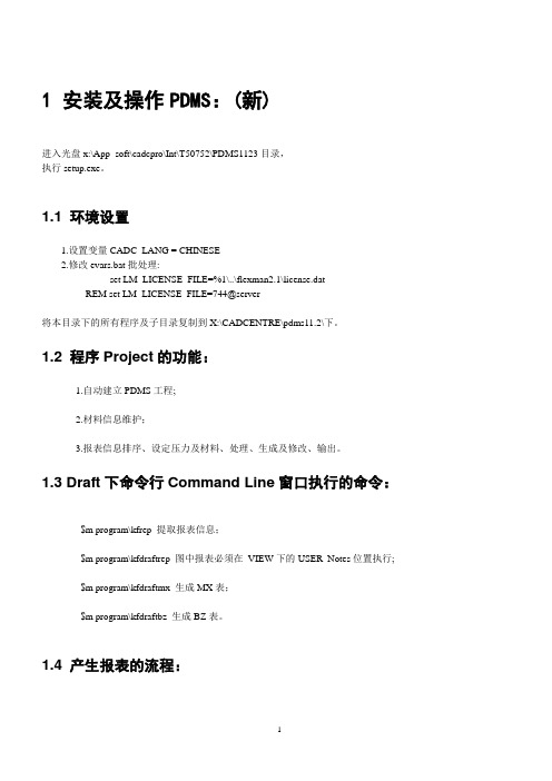
PDMS破解必看-安装说明1.⾸先运⾏pdms11.6.sp3⽂件夹⾥⾯的setup.exe安装程序,安装过程⽐较简单,⼀直点next即可2.完成后运⾏SP3.5⽂件夹⾥⾯的setup.exe进⾏升级3.升级完成后运⾏CRACK.exe进⾏破解,破解补丁⼀定要解压到PDMS的实际安装位置解压完成后会弹出⼀个这样的DOS窗⼝:按⼀下回车出现下⾯窗⼝:按⼀下回车,等待⼀下(可能要差不多1分钟)会出现⼀个破解成功的提⽰接着按下键盘上的⽅向键↓移动光标,再按回车,等待⼀会出现成功提⽰后接着按下键盘上的⽅向键↓接着破解下⼀个模块,直到10个模块全部破解完成5.让PDMS⽀持中⽂⽂件名的⽅法(仅仅是⽀持中⽂⽂件名,并不是把菜单变成中⽂的了,呵呵):在桌⾯上右键点---我的电脑---属性---⾼级---环境变量变量名输⼊Cadc_lang变量值输⼊Chinese打开PDMS以Admin模块进⼊,⽤户名(⼤写)SYSTEM密码XXXXXX,这是超级⽤户,拥有全部权限然后点Display菜单Command Line,然后在command命令⾏⾥⾯输⼊PROJECT MBCHARSET CHI然后回车:6.运⾏pdms11.6tookit.exe升级⼯具集安装完成后进⼊monitor模块,⽤户名(⼤写)SYSTEM密码XXXXXX然后点Display菜单Command Line,然后在command命令⾏⾥⾯输⼊pml rehash all退出pdms,重新以⽤户名(⼤写)PIPE密码PIPE进⼊design模块即可(平常设计也是这样进⼊程序)catview安装Catview是免费元件,安装不需要license。
安装后⽣成的⽂件及⽂件夹:Evars.bat 环境变量设置⽂件NAMEING.DOC PDMS元件命名规则PDMS catview user guider.pds ⽤户指南Catview配置:如果Catview是拷贝的,可能需要编辑Catview⽬录下的EVARS.bat,将Catview指到正确的路径上。
分析PDMS在化工管道设计中的应用
分析PDMS在化工管道设计中的应用摘要:文章以推动化工行业发展为前提,针对PDMS在化工管道设计中的应用,阐述了技术优势、功能、发展现状,并从四个环节分析了PDMS的具体应用,希望能够为化工管道设计提供可行的参考。
关键词:PDMS;化工管道;管道设计化工管道设计工作是促进化工企业发展的主要推动力,二维技术在传统的化工管道设计中占据了重要地位,随着科学技术水平的不断提高,二维技术的滞后性在科研工作中逐渐暴露出来,已经不再适应科学技术的快速发展,以至于被三维技术所取代,PDMS技术的推广,更是将化工管道设计提到了一个更加高深的层次。
1 三维技术的 PDMS 软件的优势传统的二维技术在工业领域曾占据重要的技术地位,特别是对于化工管道的设计,其举足轻重的作用一直受到各专家和技术工人的青睐,可是随着技术的革新,目前三维技术已经逐渐取代了二维技术,PDMS 已经成为管道设计的首选技术[1]。
PDMS(Plant Design Management System)是指工厂三维布置设计管理系统,这个系统其实就是一个以数据为中心的三维设计软件,并且该三维设计软件是应用普遍且相对成熟的设计软件之一,目前已经广泛用于电力、石油、化工、冶金等行业。
1.1 直观性PDMS 优与 CAD 的直观性主要体现在其作图环境上,传统的 CAD 技术作图主要是在二维空间内进行,而 PDMS 是在一个虚拟的三维空间内进行绘图。
这样一来,作图者完全可以从不同的方度查看所布置的模型,由于三维空间内模型的位置描述准确度高,在作图中设计人员对所设计的物体的空间位置可以做到一目了然,最终提高了设计的精确性。
1.2 共享性PDMS 优与 CAD 的共享性主要是指信息的共享,因为采用 PDMS 软件每一个设计人员都有机会借鉴别人的方法和技巧。
其原理是 PDMS 系统使用单一的数据库,这个数据库包括了不同专业的设计成果,同时存储了不同设计人员的作品,通过设置权限来控制系统信息的共享。
pdms实用基本操作大全

p d m s实用基本操作大全-CAL-FENGHAI-(2020YEAR-YICAI)_JINGBIAN编号:40D08-01-2008 PDMS 建模操作手册( 共24页 )编制王艳艳校对刘红新审核张林青项目审核贾正伟审定王金富配管室2008-2-26目录一、设备建模 (1)I利用设备模板建设备 (1)II参数化创建设备 (2)III读取宏文件生成设备 (2)IV 搭积木创建设备 (3)V 特殊设备基本体的构建 (4)VI 设备模块常用命令 (5)二、管道建模 (11)I基本管线的创建 (11)II常用的管线修改编辑命令 (12)三、错误信息类型及修改方法 (22)一、设备建模Ⅰ、利用设备模板建设备:1.创建 Site: Create ==> Site ==> tank1(名称)创建Zone: Create ==> Zone ==> Equipmodel2.创建设备:Utilities ==> Equipment3. 创建设备模版:Create ==> Basic Equipment,选择要创建的设备类型,输入对应的参数值。
修改属性:选中要修改的CE点Modify ==> Attributes, 修改其参数值,修改完毕后点OK即可。
Ⅱ、参数化创建设备:Create ==> Stardard ==> 输入设备名称,选择具体的设备类型,选中之后点Properities,可修改其参数值,点OK确定放置点座标即可。
参数化模型设备的修改:Modify ==> Equipment Specification ==> 点Properities, 修改其属性值。
Ⅲ、读取宏文件生成设备:1.选择要处理的源设备,生成一个宏文件Utilities ==> DB listing ==> 输入要输出的宏文件路径 ==> 点Add CE ,点Apply,这样就输出一个宏文件。
PDMS三个版本安装方法

PDMS三个版本安装方法一. PDMS11.6安装步骤1.解压11.6安装文件,运行setup.exe一路安装完毕。
(安装盘符最好选择非系统盘)2.解压PDMS11.6license,复制cra.exe pdms116.crk 和license文件到pdms11.6安装目录下。
3.双击运行cra.exe,弹出dos窗口。
4.不停按回车键,直到提示没有文件将被替换。
(大概10下)5.按ESC 返回再按F10退出。
6.设置环境变量:a.单击我的电脑右键属性_高级_环境变量:新建用户变量: cadc_lang值chinese 和 cadcentre_license_file 值744@PC名或者IP(例如744@3d 或者***********.1.110)。
7.运行pdms11.6安装目录下pdms.bat 弹出登录界面则OK了。
Toolkits安装1.中文字体f1105811901.gfb放入安装目录下。
2.减压PDMS11.6toolkits到安装目录覆盖。
3.运行pdms.bat,用user:SYSTEM ;password:XXXXXX 进SAM 项目进ADMIN模块。
4.进入界面:display_command line 在命令输入:proj mbcharset chin 保存退出。
5.在用设计user进design 可以看到菜单上有tool工具菜单。
Catview安装步骤1.减压catview11.6运行setup.exe直接安装完成。
2.打开pdms11.6安装目录下evars.bat 在后面加语句:Call d:\AVEVA\CATVIEW11.6\evars.bat 红色的是catview安装目录下evars.bat路径。
3.用user进paragon模块,选择paragon_pipework 在Utilities 里面可以看到catview。
二.PDMS11.6SP4安装步骤1.解压PDMS11.6SP4直接安装。
寰球华北规划院PDMS操作手册新
一. PDMS的简介1.PDMS的含义P lant D esign M anagement S ystem(工厂设计管理体系)PDMS是在计算机上创建全比例三维模型软件,几何+属性、图纸+报告,并非“以图形为中心(Graphic Centric)”而是“以数据为中心(DataCentric)”。
2.PDMS的特征单一的数据源、数据库易维护管理、易客户化、成熟的应用功能工具等特征。
3.PDMS数据库的类型<1>系统数据库 System Database用户(User)权限、组(Team),数据库访问模式Database)、数据库组MDBs);<2>元件数据库 Catalogue Database(s)几何形状、连接方式、描述及材料、等级规范;<3>设计数据库 Design Database(s)设备、管道、土建及结构、暖通、电缆桥架、支吊架;<4>管段数据库 Spooler Database(s)/ IsodraftDatabases(s)管件、管段、焊点、连接点;<5>特性数据库 Property Database(s)材料属性、应力分析数据;<6>用户定义属性数据库 Lexicon Database(s)/Dictionary Databases(s)UDA(User Defined Attribute) -用户定义的属性(标准属性之外);<7>二维图数据库 PADD Database(s)P roduction of A nnotated andD imensioned D rawings图形、注释、尺寸。
4.PDMS的功能及模块划分<1>项目管理模块ADMIN (项目管理)DICE (数据完整性检查)RECONFIGURER (数据库重整)LEXICON (定义用户定义属性)<2>应用模块MONITOR (用户权限控制)<3>元件库和等级库模块SPECON (等级表)PARAGON (元件库)PROPCON (特性库)<4>设计模块设备、管道、土建结构、暖通、电缆桥架、支吊架、设计模板<5>设计分析模块CLASHER (碰撞检查)DATAL (数据库列表)REPORTER (数据报表)<6>出图模块DRAFT (图纸生成)ISODRAFT (单管图生成)<7>管段下材料模块SPOOLER (管段资料输入)二. PDMS的简单安装与设置1.安装应用程序Pdms11.5sp1操作系统Window NT/2000/XP 磁盘格式是NTFS2.拷贝中文字库拷贝f1105811901.gfb到Pdms11.5sp1主目录3.安装Pdms11.5Toolkit8.5到Pdms11.5sp1主目录(Toolkits工具集随需要升版安装)安装Toolkit后,PDMS的第一次运行用个人用户名和密码进入Monitor打开命令行Display>Command Line键入Pml rehash all进入Design,Monitor>Modules>Design>Macro files…4.安装Catview11.3到C:\AVEVA\Catview11.3主目录(Catview属于外挂程序,拷贝即可使用)在Catview目录中包含三个文件Evars.bat 环境变量设置文件NAMING.DOC PDMS 元件命名规则PDMS Catview User Guide.pdf 用户指南Catview的设置编辑Catview目录中的Evars.bat,将Catview指到正确的路径上Rem Set path to the main Catview directoryset catview=C:\AVEVA\catview11.3编辑Pdms11.5主目录中的Evars.bat文件,在文件的最后调用Catview目录中的Evars.batCall C:\AVEVA\catview11.3\evars.bat重新进入Paragon,刷新程序索引文件Tools>Pml Debug>Pml rehash All或打开命令行Display>Command Line键入Pml rehash all5.License.bat文件的替换和启动方式此文件是软件厂家控制正版软件的一种手段,机号和文件是一一对应,由软件厂家提供并且不定期替换,但安装和启动均由用户完成。
PDMS教程指导
PDMS教程指导Pipework Modelling管道设计通常是一个大型项目中最费时的工作,也是产生问题最多的部分。
在PDMS中,管道建模是系统中最强大的功能之一,它最大可能地避免了设计错误的产生。
(database hierarchy)每个管道(PIPE)可以有多个分支(BRANCH),在分支下面才是具体的管件,分支与管道的不同在于分支只有两个端点,而管道可以有多个端点,这要看它有几个分支。
Branch 1Branch 2Tee? ??Branches分支有两个用途:1(定义管道的起点和终点,在PDMS 中称为Head 和Tail。
2(用分支管理管道上的所有管件。
当你定义分支的头和尾时,它会在两点之间出现一个虚线。
VANTAGE PDMS 培训手册 1HeadTail在分支下面的管件位置和顺序决定了管道的铺设。
在PDMS 中,不用添加管道,只须考虑管件,因为管道是根据管件的等级在两个相邻管件中自动生成的。
Heads and Tails所有的分支必须有起点和终点,它可以是空间的一点,嘴子的法兰面,三通或者设计中的其它点。
分支的方向必须是管道的流向。
而分支中的管件顺序同样重要,它决定了管道的最终走向。
????Nozzle 1Gasket 1Flange 1Elbow 2Nozzle 2Flange 2Gasket 2Head is at start position of Gasket 1Tail is at end of Gasket 2Elbow 1生成管件都要完成下面的步骤:1(从管道等级中选择管件。
2(定义管件位置。
3(指定出口方向。
:HPOS 分支起点的位置HCON 分支起点的连接形式(用三个字母代表法兰,对焊,螺纹等等)HDIR 分支起点的方向HBOR 分支起点管道直径HREF 与分支起点连接的元件,一般为管嘴,例如C1101-N1。
如果这个属性没有设置,那末这个分支可能是放空或排凝。
PDMS中文教程(管道等级)

VPDVANTAGE Plant Design System工厂三维布置设计管理系统PDMS管道等级培训手册目录SPECON和CATVIEW (3)CATVIEW (3)CATVIEW的安装 (3)CATVIEW的设置 (3)管道等级 (4)等级与元件库的关系 (4)CATVIEW生成管道等级 (4)等级中的选项说明 (8)等级的数据库层次 (9)等级修改 (9)向等级中添加特性库 (9)等级的工作原理 (10)等级文件中的缺省选择 (11)等级文件中的特殊字符 (11)等级使用中的注意事项 (12)SPECON (12)SPECON常用命令 (12)SPECON新建等级 (13)SPECON修改等级 (15)等级数据库检查与测试 (15)等级数据库检查 (15)等级数据库测试 (16)管嘴等级 (16)管嘴等级(Nozzle Specification) (16)生成管嘴等级 (16)保温等级 (19)保温元件库 (19)SPECON生成保温等级 (19)伴热等级 (21)SPECON和CATVIEW建立管道等级有两个方法:在SPECON模块用命令行调用MACRO文件,或用PARAGON中提供的CATVIEW用户界面完成。
CATVIEWCATVIEW的安装CATVIEW属于外挂程序,可以通过光盘安装或者直接拷贝CATVIEW目录。
CATVIEW的设置1.在CATVIEW目录中包含三个文件。
Evars.bat 环境变量设置文件NAMING.DOC PDMS元件命名规则PDMS Catview User Guide.pdf 用户指南2.打开Evars.bat将Catview指到正确的路径上Rem Set path to the main Catview directoryset catview=D:\cadcentre\catview11.33.编辑PDMS主目录中的Evars.bat文件,在文件的最后调用Catview目录中的Evars.batCall D:\cadcentre\catview11.3\evars.bat管道等级等级与元件库的关系CATVIEW生成管道等级1.使用Catview建立等级Utilities->Catview…。
PDMS操作技巧
REM set LM_LICENSE_FILE=744@server
3.将'D:\Program\OKMAC\DRA-GEN-SYSTEM、;DRAFT参数设置
des-element-rules.pmldat、
NAMEDATATYPE
建立MDB:CRAETE MDB /ABC
添加全部DB到MDB
6.加入汉字
从命令行窗口执行'PROJ MBCHAR CHI'加入汉字,(指定一个多字节字符集)
存盘。
7.
选择'Users':ABC,'MDBs':ABC;
8.
以'Macro Files'进入'Paragon'模块;
2.矩形管箍,具体结构型式、尺寸、技术要求见企业标准KFxxx_2001
3.管架支在冷箱设备上(垫板设备自带)
导向式
管架Ⅲ
1.管道公称直径DN≥100
2.特殊管架(由型材构建)
3.管架支在冷箱骨架上
管架Ⅳ
1.管道公称直径DN≥100
2.特殊管架(由型材构建)
3.管架支在冷箱设备上(垫板设备自带)
'$m d:\program\kfdraftrep';
注:最好是为明细栏专门创建一个VIEW,在该VIEW下的USER_Notes位置执行
5.因一些情况出图前请执行'$m d:\program\setpen.dat'修改线型。
2.5
1.请首先在'design'或'draft'模块的'command line'
- 1、下载文档前请自行甄别文档内容的完整性,平台不提供额外的编辑、内容补充、找答案等附加服务。
- 2、"仅部分预览"的文档,不可在线预览部分如存在完整性等问题,可反馈申请退款(可完整预览的文档不适用该条件!)。
- 3、如文档侵犯您的权益,请联系客服反馈,我们会尽快为您处理(人工客服工作时间:9:00-18:30)。
psi116/psi_user_guide116Issue 201106 Rev 1PDMS 11.6管道应力分析接口用户指南NOTE:AVEVA Solutions has a policy of continuing product development: therefore, the information containedin this document may be subject to change without notice.AVEVA SOLUTIONS MAKES NO WARRANTY OF ANY KIND WITH REGARD TO THIS DOCUMENT, INCLUDING BUT NOT LIMITED TO, THE IMPLIED WARRANTIES OF MERCHANTABILITY AND FITNESS FOR A PARTICULAR PURPOSE.While every effort has been made to verify the accuracy of this document, AVEVA Solutions shall notbe liable for errors contained herein or direct, indirect, special, incidental or consequential damages inconnection with the furnishing, performance or use of this material.This manual provides documentation relating to products to which you may not have access or whichmay not be licensed to you. For further information on which Products are licensed to you, refer to yourlicense conditions.Copyright 1991 through 2006 AVEVA Solutions LimitedAll rights reserved. No part of this document may be reproduced, stored in a retrieval system or transmitted, in any form or by any means, electronic, mechanical, photocopying, recording or otherwise, without prior written permission of AVEVA Solutions.The software programs described in this document are confidential information and proprietary products of AVEVA Solutions or its licensors.For details of AVEVA's worldwide sales and support offices, see our website at:PSI 11.6 User GuideContents-iContents1Introduction (1)1.1 About this User Guide (1)1.2 Overview of the PSI application (1)2 Starting theapplication (2)3 The Groups Tab (5)3.1 Creating a Stress Group (5)3.2 Adding and Removing Members (5)3.3 Rebuild Selected Group (7)3.4 Find a Group (7)4 The Display Tab (8)4.1 Graphics (8)4.2 Animation (10)4.2.1 Animation Speed (10)4.2.2 Processing Order (11)4.3 Active Stress Group (11)5 Menus andToolbars (13)5.1 Context menus (13)5.2 The Pipe Stress Interface toolbar (14)5.3 The Node details form (14)5.3.1 Display Options (14)5.3.2 Renumbering Nodes (14)6 Checking the Stress Group forErrors (16)6.1 Datacon Errors (16)6.2 Node Errors (16)6.2.1 Node Errors – Weight (17)7 Pipe Stress InterfaceDefaults (19)8 PDMS to CAESARII (20)PSI 11.6 User GuideContents-ii8.1 Creating a CAESAR II Neutral file (20)8.2 Converting a CAESAR II Neutral File to a CAESAR II Input file (21)8.3 Opening a CAESAR II Input File (22)9 CAESAR II toPDMS (24)9.1 Creating a Report File (24)9.2 Converting a CAESAR II Input file to a CAESAR II Neutral File (25)9.3 Naming and location of files coming back (25)9.4 Getting stress data into PDMS (25)9.5 Displaying load cases in PDMS (26)9.6 Editing Return Nodes (26)9.7 Clash checking (28)11 Introduction1.1 About this User GuideThis document provides guidance to the piping/stress engineer on how to create and configure stress groups using the Pipe Stress Interface (PSI) application. It is assumed that thepiping/stress engineer has a basic understanding of the PDMS software.This manual assumes that you are working with PDMS 11.6. PSI can work with PDMS 11.5, but you will need to read the PSI 11.6 User Guide for PDMS 11.5 instead.1.2 Overview of the PSI applicationThe PSI application allows you to create stress groups from existing pipe lines within the PDMS Design application. When a stress group has been created the PSI application will create a CAESAR II CII format file, which can be selected in CAESAR II and converted to a CAESAR II_A format file. The stress engineer can then perform stress calculations on the transferredstress group.Once the stress engineer has finished the analysis; he can create a report file (with extension.out) and a CAESAR II neutral file showing the modified pipe. These files can be then be imported back into PDMS to assist the piping engineer update the PDMS model to match.22 Starting the application1. Start the Pipework Application Figure 1 is displayed.Figure 1 Pipework Application form32. Select Utilities>Pipe Stress Interface… from the main menu Figure 2.Figure 2 Utilities pull-down menu3. A Default creation Zone form is now displayed Figure 3. Select a zone in which to createyour Stress Groups from the form and press OK.Figure 3 Default Creation Zone FormIf no zone is found, a new zone should be created with its purpose set to PSI; only zones with their purpose set to PSI will be displayed in the Default Creation Zone Figure 3. (PSI is the default selection for Stress Zones; this can be modified in the PSI defaults form)Note: A Stress Group is a PDMS pipe with a list of branches to be stressed.44. The Pipe Stress Interface form should now be displayed Figure 4.Figure 4 Pipe Stress Interface Form53 The Groups Tab3.1 Creating a Stress Group1. To create a new Stress Group, press the New Stress Group button on the Pipe Stress Interface form’s Groups tab (Figure 4). A New Stress Group Name form is displayed(Figure 5); enter the name of your new stress group and press OK. To close the window without creating a new stress group select the Dismiss button.Figure 5 New Stress Group Name FormNote: Stress Group names containing slashes are not valid and will cause later problems if used.2. Once you have created a new Stress Group it will be displayed in the Existing Groups box (Figure 6) on the Pipe Stress Interface and in the Design Explorer hierarchy if displayed.Figure 6 Existing Groups Box3.2 Adding and Removing Members1. To add branches to a Stress Group, select the Stress Group you want to add to by clickingon it in the Existing Groups list and then click the Add/Remove Members button on thePipe Stress Interface. The Pipe Stress Interface now becomes greyed out and inactive.Note: The lowest level to add to a Stress Group is a branch; branches can be split if it is necessary to stress part of a branch.2. Select the branches to include in the Stress Group by graphically selecting them using theleft mouse button. Figure 7 shows the branches to include in a stress group have been selected in red. Note: This colour might vary depending upon your configuration settings.6Figure 7 Branches included in the Stress GroupTo remove a branch which you have selected, select it again and you will be prompted with a choice to remove the selected branch from the stress group. (Figure 8)Figure 8 Remove Branch dialogue3. Once you have finished selecting the branches to include in your stress group press Esc (escape). The Pipe Stress Interface form will now become active.4. The branches that you selected to include in your stress group should now be listed in the Group Members box (Figure 9). Members can be added or removed from group at anytime by pressing the Add/Remove Members button or right clicking on a Stress Group toreveal a context menu and selecting Add CE or Remove CE. See 5.1for more details.Figure 9 Group Members Box73.3 Rebuild Selected GroupThe Rebuild Selected Group button allows you to rebuild and refresh members of the currently selected group.3.4 Find a GroupThe Find Groups button allows you to determine what Stress Groups the current element belongs to. Graphically select a branch and press the Find Groups button and a form will bedisplayed that lists the Stress Groups that the branch belongs to.84 The Display Tab4.1 GraphicsThe Graphics section (Figure 10) on the Display Tab contains two radio buttons which can be toggled between; Main Nodes and Case Nodes and three check box options; Branches, Graphics and Connected which can be checked on/off.Figure 10 Graphics sectionToggling between the Main Nodes and Case Nodes (Load case nodes returned from after stressing) shows the node numbers of the respected selection in the 3D Design window. (Figure 11)Figure 11 Nodes shown on branchChecking the Branches box shows the names of the branches in the selected Stress Group in the 3D Design window. (Figure 12)9Figure 12 Branch names shownChecking the Graphics box means that all graphics are turned on. Not checking the Graphics box only shows the current Stress Group in the 3D view, i.e. all other pipes, equipment and structures are not shown (Figure 13).Current limitation: it may be necessary to use the right-button context menu item refresh toshow the current group after un-checking the Graphics boxFigure 13 Stress Group shown onlyThe Connected box turns the equipment that is connected to the Stress Group on and off in the 3D view (Figure 14).10Figure 14 Connected equipment turned on4.2 AnimationThe Animation section on the Display Tab allows you to view the processing order of the components in a Stress Group. Firstly select the Stress Group you want to view from the Existing Group box, and then press the Show button. The individual components of the selected Stress Group will be highlighted in the 3D view in the order in which they will be processed (Figure 15).Processing OrderFigure 15 Animation to show processing order of a Stress Group4.2.1 Animation SpeedThe speed at which the processing order is display in the 3D view can be controlled by the Speed track bar (Figure 16). To view the order faster slide the bar to the right, to view the order slower slide the bar to the left.11Figure 16 Speed Track Bar4.2.2 Processing OrderBranches are processed in the order in which they appear in the Group Members box. To change this processing order select the branch you want to move in the Group Members Box (Figure 9) and click on the up or down arrows (▲▼) to the right of the box.Current Limitation: the Group Members box does not always update when the up and down arrows are selected. To force an update switch to a different stress-group and back.4.3 Active Stress GroupThe original pipe is displayed by default in red and the returned stress pipe is displayed in green by default(Figure 17), but both of these can be changed in the Interface Settings.Figure 17 Returned pipe with minimal deflections12The transparency of the currently active stress group can be altered as shown in Figure 18 (It is set toSolid as default). Both the Main Group and the currently selected Load Case can be changed independently.Off removes the current active group from the 3D view.Figure 18 Display options135 Menus and Toolbars5.1 Context menusContext menu are ones that pop up when you right-click over certain items in a form. They are used to gain access to context sensitive commands. There is one context menus on the Pipe Stress Interface linked to the items in the Existing Groups box (Figure 6).Existing Group context menuRight-clicking an item in the Existing Group box i.e. the name of a Stress group brings up a context menu as shown in Figure 19 below.Figure 19 Context Menu on the Existing Group boxTable 1 below shows the context menu items and a description of their actions.Context Menu Item DescriptionDelete current Group Deletes the currently selected Stress groupShow Node Details Brings up the Show Details form as shown in Figure 20Refresh current Group Rebuilds and refreshes members of the currently selected groupTable 1 Context Menu on the Existing Group boxFigure 20 Node Details Form145.2 The Pipe Stress Interface toolbarThe PSI toolbar (Figure 21) is located under the main menu bar.Figure 21 Main menu and toolbarsEach icon on the PSI toolbar and its assigned action or purpose is listed in Table 2 below. Show Pipe Stress Interface formModify Stress Defaults (See chapter 4)Table 2 Menu Shortcut ItemsFor more information on the Pipe modification form, please refer to the Pipework Design Using PDMS User Guide5.3 The Node details formThe Node details form (Figure 20) can also be displayed by pressing the Edit Nodes button on the Output/Input tab in addition to accessing it via the Existing Group context menu.5.3.1 Display OptionsThe columns displayed on the Node Details form can be customised from the Pipe Stress Interface Defaults Form (See chapter Error! Reference source not found.).The Node Details form has two radio buttons (Figure 22). Selecting All Nodes displays all node on the form (inactive and active nodes), selecting Active Nodes just displays active nodes i.e. those nodes with a node number.Figure 22 Display Format5.3.2 Renumbering NodesNodes of a stress group can be renumbered by pressing the Renumber Nodes button located on the Node Details Form (Figure 23).15Figure 23 Node Renumbering FormSingle Node RenumberingTo renumber a single node, select the appropriate node in the list and enter a new node number in the New Number text box. Press Update Numbers to view the changes and then press Apply to save the changes.N.B If you choose a node number that is already in use then you will be asked if you want to renumber all subsequent nodes; these will be renumbered according to the increment value in the Increment text box.Cascading Node RenumberingWhen you select a node to be renumbered using the Cascade option, all subsequent nodes are also renumbered according to the increment value in the Increment text box.Reset ButtonThis resets all nodes to their original node numbers.166 Checking the Stress Group for ErrorsThe Check Group button on the Output/Input tab checks the selected Stress Group for Datacon and Node errors. When the Check group button is pressed it displays a tabbed window (Figure 24). Results from the checks are displayed under the appropriate tab.Figure 24 Pipe Stress System Errors form6.1 Datacon ErrorsThe Datacon errors tab displays Data Consistency errors for each branch in the Stress Group.6.2 Node ErrorsThe Node errors tab shows problems such as the component weight not being set. These errors should be rectified before the pipe is sent to be stressed.176.2.1 Node Errors – WeightIf the weight of a component such as an instrument is not set, then an error in the Node Errors tab will be display:Unable to Find Weight for INST /FE-117INST =15392/5691As there is no weight is the catalogue for this, it can be set locally in the design by use of a UDA (User-defined Attribute) called PSIWEIGHT. The PSIWEIGHT attribute’s value remains persistent once set and overrides the catalogue value.To set the PSIWEIGHT UDA modify the component’s attributes by selecting: Modify>Attributes from the main menu.Note: To see changes to the list of Datacon and Node Errors, refresh the Stress Group (See 5.1 Context menus) before pressing the Check Group button. This will insure that all changes to the Stress Group are up to date.Setting a temporary weight for a Stress Run1. In the Existing Group box (Figure 6), right-click on the selected stress group and select Show Node Details from the context menu. See Figure 19 for more details.2. The Node Details from will now be displayed (Figure 20).3. Locate the component that’s weight needs to be change. (If the weight is zero the Error column will be flagged as True on the Node Details form)4. Right-click anywhere on the component’s row to bring up a context menu (Figure 25).Figure 25 Display Node Attributes5. Select Display node attributes from the context menu.Alternatively press the Node Attributes button the Node Details Form.6. A form will be displayed with the majority of the fields being read-only. However if the weight is zero then the weight field can be changed. Once you have changed the weight to asuitable value, press Apply and a message will be displayed warning you that the changes made by this method are only temporary. See Figure 26.18Figure 26 Confirmation MessageNote: Further changes to weight values can be made within Caesar II.197 Pipe Stress Interface DefaultsThe PSI defaults form allows the user to configure PSI to suit the user’s project data. This can be configured in many ways so it is important to provide facilities to use this data rather than make project changes to suit PSI.The defaults file is principally used to tell PSI where to extract information and what units to expect, but it also defines how PSI works in the user environment.When the Modify Stress Defaults icon is pressed from the PSI toolbar, the StressInterface Defaults form is displayed (Figure 27).Figure 27 Stress Interface Defaults FormThe Stress Interface Defaults form has five tabs:Database UnitsInterface SettingsExpressionsRestraint DataNode Form Display ColumnsFor information on how to use the PSI defaults form, please see the PSI Admin guide.208 PDMS to CAESAR II8.1 Creating a CAESAR II Neutral fileTo create a CAESAR II Neutral file for a selected Stress Group, press the Write Data to cii file button on the Output/Input tab.It is now very important to do a Save Work immediately after creating a CAESAR Neutral File so that all data relating to the Stress Group is saved within PDMS.Once the button has been pressed three folders called input, output and logs are used to store the data. They are located in the same area as the project directories e.g.C:\ProjectPath\Project\Sampsi where the name of the project is Sam. The files contained within these folders are named according to the name given to your Stress Group. See Table 3.The input folder contains the newly created CAESAR II Neural File (*.cii) which can be input into Caesar II.The output folder contains an xml file which contains pipe stress data exported from PDMS in a predefined schema.The logs folder contains a HTML reports viewable via a web browser: _log.html which contains information about the conversion from the *.xml file to the Caesar II Neural File. The _log.html contains version information for the .cii converter, and also any messages to do with the running of the conversion process – it is a good place to look if things go wrong. It also contains information about the PDMS elements translated, and any assumptions and default values used (for example missing weights or wall thicknesses). The stress engineer may find it useful to have a look at this file.Folder Name(To CAESAR)(From PDMS)Examples offilesproducedTable 3 Input and Output Folders218.2 Converting a CAESAR II Neutral File to a CAESAR II InputfileIt is necessary to convert the neutral file created in the Pipe Stress interface to a Caesar II Input file beforethe Stress Group can be viewed and analysed in Caesar II.1. Start up Caesar II and Select Tools>External Interfaces>CAESAR II Neutral File… fromthe main menu (Figure 28).Figure 28 Tools pull-down menu2. A Neutral File Generator box should now be displayed (Figure 29). Select the first radio button labelled “Convert Neutral File to CAESAR II Input File”.3. Press the Browse button and navigate to the *.cii file in the input folder created by the Pipe Stress Interface.4. Press the Convert button. A message confirming the conversion should be displayed.22Figure 29 Neutral File Generator box8.3 Opening a CAESAR II Input FileIn Caesar II, Select File>Open… from the main menu, select the Caesar II Input File (*._A) and press Open (Figure 30).Figure 30 Opening a Caesar II Neutral FileSelect Input>Piping… from the Main menu to display the Caesar II piping input spreadsheet which contains all the information of the Stress Group created in PDMS. (Figure 31)23Figure 31 Piping Input Spreadsheet249 CAESAR II to PDMSIn order to bring back stress data from CAESAR to PDMS two CAESAR files need to be created; Report File (*.OUT) containing Displacement data for one or more Load CasesNeutral file(*.CII) of the stress pipe9.1 Creating a Report FileIn CAESAR II open the appropriate piping input file (*._A) (Figure 30) which should now be ready to be stressed and has been error checked in CAESAR. Then select Output > Static from the main menu to display the Static Output processor screen (Figure 32).Figure 32 Static Output Processor ScreenNext, select one or more load cases under Load Cases Analysed. For information on editing load cases please see the CAESAR II User Guide. Then Select Displacements under Report Optionswhich will output translations and rotations for each node. Other report options may be selected too, but are not passed back into PDMS.Note: It is important to select the 132 column report option under Miscellaneous Options rather than the standard 80 column report, otherwise PSI might encounter problems reading back the data.Note: It is advised that you don’t add the optional two title lines in CAESAR for similar reasons as above.Now save the report file File> Save.259.2 Converting a CAESAR II Input file to a CAESAR II NeutralFileIn order for PDMS to determine if any changes have been made to the stress pipe within CAESAR, the current piping input file needs to be converted to a neutral file.N.B It is important that this step is implemented either directly before the producing the report file or directly after, so that the representation of the pipe in consistent in both files.1. Select Tools>External Interfaces>CAESAR II Neutral File… from the main menu (Figure 28).2. A Neutral File Generator box should now be displayed (Figure 29). Select the second radiobutton labelled “CAESAR II Input File to Neutral File”.3. Press the Browse button and navigate to the appropriate *._A file.4. Press the Convert button. A message confirming the conversion should be displayed.9.3 Naming and location of files coming backIn order for PDMS to find the two new files from CAESAR (neutral and report) they need to be saved to the Input directory which is located in the same area as the project directories e.g.C:\ProjectPath\Project\Sampsi where the name of the project is Sam. The naming of the files is also important; the new files should have the same name as the corresponding XML file in the output folder.9.4 Getting stress data into PDMSTo get data back into PDMS, select a Stress Group from the Existing Groups box (Figure 6) which hasbeen stressed in CAESAR and has a corresponding neutral and report file in the input folder. Now press the Convert Stress Data button on the Output/Input tab. If this is successful a new XML file(StressGroupName Ret.XML) will be created and saved to the return folder.If for any reason the process fails e.g. the CAESAR report file is missing, then an error will be displayed(Figure 33).Figure 33 PSI ErrorA HTML log (*_RetLog.html) is also created and stored in the logs folder every time the Convert Outputbutton is pressed. The log gives more detail on what the conversion process has found and where, if any26problems have occurred. Any Errors will be highlighted in Red, Warnings in Blue and Restraints in green.9.5 Displaying load cases in PDMSOnce a return XML file has been created it can be opened and loaded into CAESAR by pressing the Read Stress File button on the Output/Input Tab. The return XML files should all be stored in the return folder and the file browser should automatically navigate to this.Figure 34 Load Case ModelsNote: Make sure you have the corresponding Stress Group selected in the Existing Groupsbox so that the main pipe and load case models can be shown in the 3D view.Note: You may have to re-select the Stress Group after opening the file to see the changes.The Load Case Model list should now be populated with a list of load cases; any invalid load cases will be deleted. To view different load cases overlaid on the original pipe, simply select the required load case from the list.9.6 Editing Return NodesReturn nodes can be edited by pressing the Edit Return Nodes button on the Output/Input tab. Once this button is pressed a Node Details form will be displayed containing information on the returnednodes.27Figure 35 Return Node Details FormThe return node details form includes two new columns; deflection and status. Deflections are set foractive nodes that have been stressed and have deflection data returned to PDMS. The status column isalso set for active nodes. Any new nodes will be set to “New”; deleted nodes will be set to “Deleted” andnodes which are unchanged are set to “False”.New NodesNew nodes that have been added in CAESAR e.g. an expansion loop will be displayed in PDMS as nodenumbers in space connected by a dotted line, as can be seen inFigure 36.28Figure 36 New nodes added in CAESAR and displayed in PDMS9.7 Clash checkingLoad cases can be clash checked by pressing the clasher icon on the Output/Input tab . Select theload case you want to clash check from the list of load case models and press the clasher icon. Any itemsthat clash will be added to the draw list.End of document。