泰克曼多功能功率计量插座TM10
阿尔卡特朗讯 OmniSwitch TM 10K 交换机 说明书

RFC 1321 MD5 RFC 2104 HMAC 消息认证 RFC 2138/2865/2868/3575/2618 RA-
RIP RFC 1058 RIP v1 RFC 1722/1723/2453/1724 RIP v2 和
MIB RFC 1812/2644 IPv4 路由器要求 支持 IPv6 的 RFC 2080
BGP
RFC 1269/1657 BGP v3/v4 MIB RFC 1403/1745 BGP/OSPF Interaction RFC 1771-1774/2842/2918/3392 BGPv4 RFC 1965 BGP AS 联盟 RFC 1966 BGP 路由反射 RFC 1997/1998 BGP 团体属性 RFC 2042 BGP 新属性 RFC 2385 BGP MD5 签名 RFC 2439 BGP 路由摆动抑制 RFC 2545 BGP-4 多协议扩展,用于 IPv6
讯 1x1 STP 模式 IEEE 802.3ad 链路聚合控制协议(LACP)
和静态 LAG 组
融合网络(QoS) 优先级队列:每个端口最少具有 8 个基
于硬件的优先级 流量优先级:基于数据流的 QoS 基于数据流的带宽管理 具有可配置调度算法的队列管理 WRED DiffServ 体系架构 IPv4 路由 多虚拟路由转发(VRF) 静态路由、路由信息协议(RIP)v1 和 v2 OSPF v2 支持平滑重启 BGP v4 支持平滑重启 (GRE)隧道 VRRP v2 IPv6 路由 多虚拟路由转发(VRF) 静态路由 下一代路由信息协议(RIPng) OSPF v3 BGP v4(支持 IPv6) OSPF 和 BGP 平滑重启 VRRP v3 NDP
Eaton 天气保护插座盒说明书
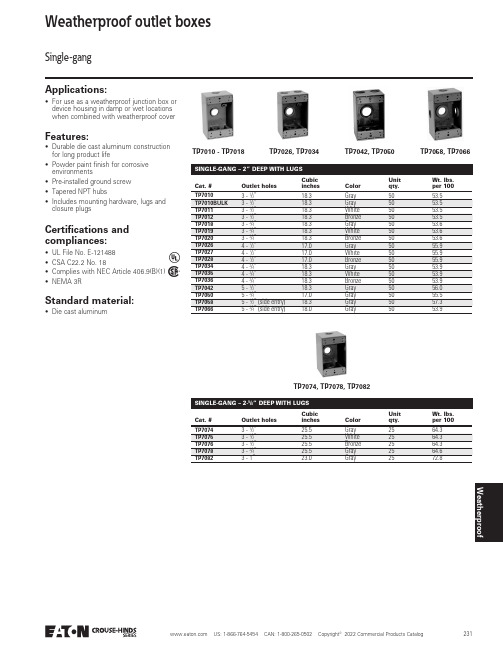
WeatherproofWeatherproof outlet boxesApplications:• For use as a weatherproof junction box or device housing in damp or wet locations when combined with weatherproof coverCertifications andcompliances:TP7010 - TP7018TP7026, TP7034TP7042, TP7050TP7058, TP7066TP7074, TP7078, TP7082Standard material:• D ie cast aluminumCat. #Outlet holesCubic inchesColorUnit qty.W t. lbs. per 1003 - 1/”18.3Gray 5053.5TP70665 - /4” (side entry)18.0Gray 5053.9Single-gangFeatures:• Durable die cast aluminum construction for long product life• Powder paint finish for corrosive environments• Pre-installed ground screw • Tapered NPT hubs• Includes mounting hardware, lugs and closure plugs• UL File No. E-121488• CSA C22.2 No. 18• Complies with NEC Article 406.9(B)(1)• NEMA 3RSINGLE-GANG – 2-/” DEEP WITH LUGS Cat. #Outlet holesCubic inchesColorUnit qty.W t. lbs. per 100TP70743 - 1/”25.5Gray 2564.3TP70823 - 1”23.0Gray 2572.8Weatherproof outlet boxes Applications:• For use as a weatherproof junction box ordevice housing in damp or wet locationswhen combined with weatherproof coverCertifications and compliances:Standard material:• D ie cast aluminum Cat. #Outlet holesCubicinches ColorUnitqty.W t. lbs.per 100TP70863 - 1/”30.2Gray1084.7TP71287 - /4” (side entry)31.0Gray1081.4Two-gang and three-gang Features:• Durable die cast aluminum construction for long product life• Powder paint finish for corrosive environments• Pre-installed ground screw• Tapered NPT hubs• Includes mounting hardware, lugs and closure plugs• UL File No. E-121488• CSA C22.2 No. 18• Complies with NEC Article 406.9(B)(1)• NEMA 3RTP7086 - TP7090TP7093TP7094, TP7098TP7102, TP7106 TP7118, TP7122TP7110, TP7114TP7125TP7128TP7126, TP7130,TP7134TP7137, TP7138,TP7142TP7143TP7144 TWO-GANG – 2-/” DEEPCat. #Outlet holesCubicinches ColorUnitqty.W t. lbs.per 1005 - 1/”36.0Gray6102.6THREE-GANG – 2-/” DEEPCat. #Outlet holesCubicinches ColorUnitqty.W t. lbs.per 100TP71437 - 3/”55.0Gray5139.2Weatherproof outlet boxes Applications:• For use as a weatherproof junctionbox, device housing or as a lampholdermounting in damp or wet locationsStandard materials:• B oxes – die cast aluminum • Gaskets – polyethylene foam 4” ROUND – 1-/” DEEP ACat. #Outlet holesCubicinches ColorUnitqty.W t. lbs.per 100TP71465- 1/”16.0Gray2543.8Round boxesFeatures:• Durable die cast aluminum construction for long product life• Powder paint finish for corrosive environments• Pre-installed ground screw• Tapered NPT hubs• Boxes include mounting hardware and closure plugs• Covers include gasket and mounting hardwareCertifications and compliances:• UL File No. E-121488• CSA C22.2 No. 18• cULus• Complies with NEC Article 406.9(B)(1)• NEMA 3RWITH BLANK PLATE BCat. #Outlet holesCubicinches ColorUnitqty.W t. lbs.per 100TP71475- 1/”16.0Gray2467.4TP7146TP7147 - TP7151TP71584” ROUND BLANK PLATE COVERS BCat. #Outlet holesCubicinches ColorUnitqty.W t. lbs.per 100TP7158––Gray5024.0TP7160––Bronze5024.0A UL Listed and CSA certified.B cULus Listed.WeatherproofWeatherproof outlet boxesExtensions and adaptersApplications:• To provide weatherproof outlet boxes with additional capacity for larger wire fill requirementsStandard material:• D ie cast aluminumFeatures:• Durable die cast aluminum construction for long product life• Powder paint finish for corrosive environments• Tapered NPT hubs• Includes gasket, mounting hardware and closure plugsCertifications and compliances:• UL File No. E-121488• CSA C22.2 No. 18• cULus• Complies with NEC Article 406.9(B)(1)• NEMA 3RTP7120TP7123TP7152TP7171TP7172TP7173TP7177TP7183TP7258A Cat. #Outlet holesCubic inchcapacityColorUnit qty.W t. lbs. per 100TP7120–9.5Gray 2520.7/” DEEP A Cat. #Outlet holesCubic inch capacityColorUnit qty.W t. lbs. per 100TP7171 2 - 1/”9.5Gray 640.9SINGLE-GANG FLANGED EXTENSION ADAPTERS – 1-/” DEEP B Cat. #Outlet holesCubic inch capacityColorUnit qty.W t. lbs. per 100TP72584 - 1/2”12.5Gray 647.2TWO-GANG EXTENSION – 1” DEEP C Cat. #Outlet holesCubic inch capacityColorUnit qty.W t. lbs. per 100TP7123–16.0Gray 1026.74” ROUND BOX ADAPTER – 1-/” DEEP Cat. #Outlet holesCubic inchesColorUnit qty.W t. lbs. per 100C 4 - 1/”16.5Gray 2541.6TP7155B 4 - /2”16.5Bronze 2538.0A UL Listed and CSA certified.B cULus Listed.C UL Listed.Weatherproof outlet coversTP7199TP7202TP7206 - TP7209TP7214TP7218 TP7236 - TP7238TP7240 - TP7242TP7232TP7285TP7200TP7239 Single-gangApplications:• Used to provide weatherproof protectionfor outdoor receptaclesCertifications andcompliances:Standard materials:• C overs – die cast aluminum• Gaskets – polyethylene foam Features:• Durable die cast aluminum constructionfor long product life• Self-closing cover provides weatherproofprotection when device not in use• Powder paint finish for corrosiveenvironments• Includes gasket and hardware• UL File No. E-121488• CSA C22.2 No. 18• Complies with NEC Article 406.9(B)(1)• NEMA 3RTP7212TP7217TP72653-in-13-in-1WeatherproofCat. #Description ColorMounting orientationUnit qty.W t. lbs. per 100A Duplex Gray Vertical 5029.3Weatherproof outlet coversSingle-gangA UL Listed and CSA certified.B cULus Listed.WeatherproofWeatherproof outlet coversTwo-gangApplications:• Used to provide weatherproof protection for outdoor receptaclesStandard materials:• C overs – die cast aluminum • Gaskets – polyethylene foamFeatures:• Durable die cast aluminum construction for long product life • Self-closing cover provides weatherproof protection when device not in use • Powder paint finish for corrosive environments• Includes gasket and hardwareCertifications and compliances:• UL File No. E-121488• CSA C22.2 No. 18• cULus• Complies with NEC Article 406.9(B)(1)• NEMA 3RTP7220TP7224TP7228TP7244TP7222TP7248TP7252TP7270TP7271Cat. #Description ColorUnit qty.W t. lbs. per 100A Two single receptacles and/or switches, 1.406” roundGray 1062.7TP7271C20/30/50A receptacle, 2.125” roundGray860.2A UL Listed and CSA certified.B cULus Listed.C UL Listed.9-in-1Weatherproof outlet coversTP7268Single-gang and two-gang toggle switchApplications:• Used to provide weatherproof protection for an outdoor switchStandard materials:• C overs – die cast aluminum • Gaskets – polyethylene foamFeatures:• Durable die cast aluminum construction for long product life• Powder paint finish for corrosive environments• Includes gasket and hardwareCertifications and compliances:• UL File No. E-121488• CSA C22.2 No. 18• cULus• Complies with NEC Article 406.9(B)(1)• NEMA 3RTP72605/8” thickTP7278TP7275TP7280TP7277SINGLE-GANG Cat. #DescriptionColorUnit qty.W t. lbs. per 100B Toggle switch cover with SP 125V 15A switch Gray 5026.8TP7275BToggle switch cover with 3-way 125V 15A switchGray5028.8TP7269TWO-GANG Cat. #DescriptionColorUnit qty.W t. lbs. per 100C Toggle switch coverGray 1034.3TP7272BToggle switch cover with (2) SP 125V 15A switches Gray 1051.8A UL Listed and CSA certified.B cULus Listed.CUL Listed.TP7272WeatherproofWeatherproof outlet coversBlank steel and lampholderApplications:• Lampholder covers provide a mounting location for single-gang or 4” round weatherproof outlet box • Blank steel covers provide weatherproof protection when box is not in useStandard materials:• B lank covers – steel• Lampholder covers – die cast aluminumFeatures:Lampholder cover:• Durable die cast aluminum construction for long product life • Provide mounting for lampholders and accessories• Powder paint finish for corrosive environments• Two- and three-hole covers include two closure plugs• Includes gasket and hardware Blank cover:• Stamped steel• Includes gasket and hardwareCertifications and compliances:• cULus File Nos. E-121488, E163827• Complies with NEC Article 406.9(B)(1)• NEMA 3RTP7292 - TP7294TP7296 - TP7298TP7295TP7158 -TP7160TP7291Cat. #DescriptionOutlet holesColorUnit qty.W t. lbs. per 100Single-gang –Gray 10014.0TP71604” round –Bronze 5024.0TP7320 -TP7322TP7300 - TP7302TP7304TP7308 - TP7310TP7312 - TP7314LAMPHOLDER Cat. #DescriptionOutlet holesColorUnit qty.W t. lbs. per 100TP73004” round 1 - 1/”Gray 2512.0Receptacle/cover combinations and complete kitsApplications:• Receptacle kits are used to provide weatherproof protection for included devicesStandard materials:• Outlet boxes and covers – die cast aluminum• Gaskets – polyethylene foamFeatures:• Suitable for use in wet locations when cover is closed • Durable die cast aluminum construction for long product life • Complete kits offer universal mounting • Powder paint finish for corrosive environments• Includes gasket, hardware and closure plugsCertifications and compliances:• cULus File No. E-324138• Complies with NEC Article 406.9(B)(1)• NEMA 3RCat. #DescriptionOutlet holes Box depth Mounting orientationColorUnit qty.W t. lbs. per 100TP7279Single-gang multi-use cover with SP 125V 15A switch––Vertical Gray 826.8TP7279TP7400TP7404WeatherproofExtra duty non-metallic while-in-use coversApplications:• Designed to provide weatherproof protection while an outlet is in useStandard materials:• Body and cover – polycarbonate • Gaskets – polyethylene foamFeatures:• Corrosion-resistant, non-conductiveUV-rated polycarbonate for long outdoor life • Corner ball joint hinge for true universal mounting capability• No disassembly required for vertical or horizontal mounting orientation• Adapters for decorator and GFCI devices, duplex receptacles, switches and round receptacles• Keyhole provision for easy mounting • Pre-installed gasket, mounting hardware and installation instructions included • Easy to close lockable coverCertifications and compliances:• cULus – File Nos. E102328 & E15022• cCSAus• Complies with NEC Article 406.9(B)(1)• NEMA 3RWIU1T1WIU1G1WIU1DT1WIU1DG1WIU2DT1WIU2DG1Cat. #Gang Description Mounting Color DepthUnit qty.W t. lbs. per 100WIU1T11Extra duty, 16:1Horizontal/vertical Transparent gray 2.25”631.716:1 single-gang configurations55:1 double-gang configurations1-1/4” – 2-1/8”1-1/4” – 2-1/2”1-1/4” – 1-3/4”1-1/4” – 1-3/4”Extra duty metallic while-in-use coversApplications:• Designed to provide weatherproof protection while an outlet is in useStandard materials:• Body and cover – die cast aluminum • Gaskets – polyethylene foamFeatures:• Durable die cast, powder coated aluminum construction • Corner ball joint hinge for true universal mounting capability• No disassembly required for vertical or horizontal mounting orientation• Adapters for decorator and GFCI devices, duplex receptacles, switches and round receptacles• Keyhole provision for easy mounting • Pre-installed gasket, mounting hardware and installation instructions included• Easy to close lockable coverCat. #Gang Description Mounting Color DepthUnit qty.W t. lbs. per 100WIUM1G11Extra duty, 16:1Horizontal/vertical Gray 2.25”660.0WIUM2DB12Extra duty, 55:1Vertical Bronze 3.125”384.6WIUM1B1WIUM1DG1WIUM2DG116:1 single-gang configurations55:1 double-gang configurations1-1/4” – 2-1/8”1-1/4” – 2-1/2”1-1/4” – 1-3/4”1-1/4” – 1-3/4”Certifications and compliances:• cULus – File Nos. E102328 & E15022• cCSAus• Complies with NEC Article 406.9(B)(1)• NEMA 3RWeatherproofExtra duty low profile while-in-use coversApplications:• Low profile design that providesweatherproof protection while an outlet is in use and the cover is closedStandard materials:• Body and cover – polycarbonate • Gaskets – polyethylene foamFeatures:• Corrosion-resistant, non-conductiveUV-rated polycarbonate for long outdoor life • Horizontal and vertical mounting options • No cord bending inside the cover• Adapters for duplex and GFCI receptacles included• Rated for 15A • Easy to close lockable cover• Pre-installed gasket, mounting hardware and installation instructions includedCertifications and compliances:• cCSAus• Complies with NEC Article 406.9(B)(1)• NEMA 3RCat. #Gang Description Mounting Color DepthUnit qty.Wt. lbs. per 100WIUS1VT11Extra duty, low profile Vertical Transparent gray 1.562”645.2Extra duty, low profile Gray 1.562”Extra duty, low profile White1.562”Extra duty, low profile Transparent gray 1.562”WIUS1VW1WIUS1VG1WIUS1HT1WIUS1HG1Extra duty while-in-use kitsApplications:• While-in-use cover kits are used to provide weatherproof protection for included devicesStandard materials:• Outlet boxes – die cast aluminum • Metallic covers – die cast aluminum • Non-metallic covers – polycarbonate • Gaskets – polyethylene foamFeatures:• Kits include single-gang outlet box, in-use cover and 15A TRWR GFCI device • Corner ball joint hinge for true universal mounting capability • Includes pre-installed gasket, mounting hardware and closure plugs •Easy to close lockable coverWIUKGFG1WIUKMGFG1Cat. #DescriptionMountingColorOutlet holesBox depthUnit qty.W t. lbs. per 100WIUKGFC1Single-gang box and in-use cover, 15A TRWR GFCI receptacle Horizontal/vertical Transparent gray 3 - 1/” 3 - 1/”4108.9METALLIC IN-USE COVER KIT Cat. #DescriptionMountingColorOutlet holesBox depthUnit qty.W t. lbs. per 100WIUKMGFG1Single-gang box and in-use cover, 15A TRWR GFCI receptacle Horizontal/vertical Gray 3 - 1/2” 3 - 1/8”4140.2Certifications and compliances:• cULus – File No. E324733• cCSAus• Complies with NEC Article 406.9(B)(1)• NEMA 3RWeatherproofWeatherproof LEDFeatures:• Durable die cast aluminum construction for long product life• Tool-free adjustable head lamps • Powder paint finish for corrosive environments• 3000K warm white color • Voltage – 120/277V• Long life, up to 12 years• Closure plugs, gasket and hardware included• Suitable for wet locationsStandard materials:• L uminaire housing – die cast aluminum • L ens – polycarbonateApplications:• LED weatherproof luminaires combine the energy efficiency of LED technology with rugged weatherproof construction to provide a versatile residential or commercial outdoor lighting solutionCertifications and compliances:• cULus Listed• UL File Nos. E470512 and E514227Standard finish:• Painted powder coatTPLEDSL7GTPLED12GTPLEDK24GSINGLE LUMINAIRESCat. #Description Lumens ColorSize / outlet holesUnit qty.W t. lbs. per 100TPLED12G(1) 12W LED lampholder 1,000Gray 1/”4155.0TPLED12B (1) 12W LED lampholder 1,000Bronze /2”4155.0KITSCat. #Description Lumens ColorSize /outlet holesUnit qty.Wt. lbs. per 100TPLEDK24G (2) 12W LED lights, 4” round box and cover 2,000Gray 5 - 1/”2252.9SPIKE LIGHTSCat. #Description Lumens ColorSize / outlet holesUnit qty.W t. lbs. per 100TPLEDSL7G (1) 7W LED spike light 500Gray –697.9TPLEDSL7B(1) 7W LED spike light 500Bronze –697.9Lampholders and accessoriesTP7162 - TP7165TP7166TP7178TP7186TP7188 (aluminum)Cat. #Description ColorUnitqty.W t. lbs.per 100AU Universal par lampholder Natural3630.6TP71882-/2” outside dia. pole fitter with /2” male thread Gray2457.6A UL Listed and CSA certified.B cULus Listed.U Third party certified for use with CFL and LED lamps.Features:• Durable die cast construction• Adjustable lampholders• For use with Par38 bulb (150W maximum)• Includes installation hardware, gasket,closure plugs and instructionsStandard material:• D ie cast aluminumApplications:• For use in outdoor lighting applicationsCertifications andcompliances:• UL File No. E195204• CSA C22.2 No. 250.0-08• cULusWeatherproofMotion sensorsFeatures:• Motion detection with Passive Infrared Technology (PIR)• Set for motion detection or dusk to dawn • 240 degree field of view• Adjustable sensitivity from 5 to 70 feet • Selectable ON time (Test, 1, 5 or 20 minutes)Standard material:• N on-metallicApplications:• For use with LED or standard lighting kits in outdoor applicationsCertifications and compliances:• cULus Listed• UL File No. E-464470Cat. #Description ColorUnit qty.W t. lbs. per 100WPMSGMOTION SENSOR GRY Gray 233.1WPMSWMOTION SENSOR WHT White 233.1On-TimeMinutes15Test20SensitivityFeet 570Set Mode3hrs5hrsMotionDusk To DawnLampholder combinationsFeatures:• Durable die cast construction • Adjustable lampholders• For use with Par38 bulb (150W maximum)• Certified for use with CFL and LED lamps • Includes installation hardware, gasket, closure plugs and instructionsStandard material:• D ie cast aluminumApplications:• For use in outdoor lighting applications with single-gang rectangular or 4” round weatherproof boxCertifications and compliances:• cULus• UL File No. E195204TP7325TP7334Cat. #DescriptionOutlet holesColorUnit qty.W t. lbs. per 100TP7325(1) par lampholder1 - 1/”Gray 842.1TP7328TP7330 - TP73324” ROUND COVER COMBINATIONS Cat. #DescriptionOutlet holesColorUnit qty.W t. lbs. per 100TP7328(1) par lampholder 1 - 1/”Gray 842.6Lampholder kitsFeatures:• Ready to install lighting kit • Durable die cast construction • Adjustable lampholders• For use with Par38 bulb (150W maximum)• Certified for use with CFL and LED lamps • Includes installation hardware, gasket, closure plugs and instructionsStandard material:• D ie cast aluminumApplications:• For use in outdoor lighting applicationsCertifications and compliances:• cULus• UL File No. E195204TP7340TP7345Cat. #DescriptionOutlet holesColorUnit qty.W t. lbs. per 100TP7340Box, cover, (2) lampholders2 - 1/”Gray 4129.0TP7346Box, cover, photocell, (2) lampholders 2 - /2”White 4163.4Weatherproof accessoriesStandard materials:• Z inc die cast or polycarbonateApplications:• For use with all weatherproof boxes, adapters and lampholder/combination covers to seal unused outletsCertifications and compliances:• cULus• UL File No. E121487CLOSURE PLUGS Cat. #Description Material ColorUnit qty.W t. lbs. per 100TP79401/”Zinc Gray 100 1.2TP79481”Zinc Gray 50 2.8WEATHERPROOF MOUNTING HARDWARE KITCat. #DescriptionUnit qty.W t. lbs. per 100WPMH1Lugs and mounting screws1 1.2Standard material:• P olyethylene foamApplications:• For weatherproof boxes and covers • Single- and two-gang gaskets canaccommodate duplex, GFCI, round and switch devicesREPLACEMENT GASKETS TPG1TPG2TRPG1Cat. #DescriptionColorUnit qty.Wt. lbs. per 100TPG1(2) single-gang Black 200.4TRPG1(2) 4” round Black 500.3WPMH1。
Heka EPC 10 USB 电子吸管电流仪家族用户指南说明书
Smart Ephys. The Smart Source for All Your Ephys Needs.Fully computer-controlled Patch Clamp AmplifiersIntroductionThere are many advantages to a fully digitally-controlled patch clamp amplifier. Three major advantages em-ployed in the design of the EPC 10 USB are:• First, since all of the functions of the amplifier are controlled by a data acquisition program all of the amplifiers hardware settings can be stored along with the data. Not only is this capability important when reviewing and ana-lyzing the data but also for complete and thorough experimental book-keeping.• S econd, computer control allows a number of operations to be fully automated. These can include automaticmode switching (e.g. switching between the settings for establishing a seal or those for single-channel recording), automatic capacitance neutralization of C-Fast and C-Slow, and series resistance compensation. In fact, digital control of every adjustable parameter in the amplifier circuitry is implemented including full functionality test and calibration. • Finally, the integration of the amplifier, data acquisition interface and software allows experiments to be easily repli-cated to exact details.1) Electronic Design of the Patch Clamp. F .J.Sigworth. Single-Channel Recording, Second Edition, edited by Bert Sackmann and Erwin Neher. Plenum Press, New York, (1995) 95-127.2) Design of the EPC-9, a computer–controlled patch-clamp amplifier. 1. Hardware, F .J.Sigworth, Journal of Neuroscience Methods 56 (1995) 195-202.3) Design of the EPC-9, a computer–controlled patch-clamp amplifier. 2. Hardware, F.J.Sigworth, H.Affolter, E.Neher, Journal of Neuroscience Methods 56 (1995) 203-215.HEKA is very proud to release the EPC 10 USB - the newest member of the EPC 10 family of fully com-puter-controlled patch clamp amplifiers. The EPC 10 USB continues the HEKA commitment to provide the most up-to-date and technologically advanced pro-ducts for scientific research. The EPC 10 USB is the successor to the revolutionary EPC 9 patch clamp amplifier, which was introduced in 19901)2)3), as well as the renowned EPC 10.The EPC 10 USB patch clamp amplifier is available with either one (EPC 10 USB), two (EPC 10 USB Double), three (EPC 10 USB Triple) or four (EPC 10 USB Quadro) integrated amplifier modules.The EPC 10 USB is fully integrated with HEKA´s new LIH 8+8 data acquisition interface. The LIH 8+8 is a high resolution, low noise scientific data acquisition in-terface that utilizes the latest Analog to Digital, Digital to Analog, USB 2.0 and high-speed processor techno-logies. This powerful hardware combination in con-junction with PATCHMASTER or PATCHMASTER NEXT software provides a highly-integrated system that will minimize total recording noise, eliminate compatibility problems, reduce additional equipment expense, and most importantly, set-up time.ApplicationsThe EPC 10 USB family of amplifiers can be used, for example, for any of the following applications:• Low noise single-channel recordings• Low noise whole-cell patch clamp recordings: voltage clamp and cur-rent clamp/Low Frequency Voltage Clamp (LFVC)• Measurements of fast action potentials (AP), fast switching between voltage and current clamp and vice versa.• Loose-patch recordings4).• Intracellular voltage recordings with high resistance electrodes.• Field potential recordings.• Recordings from artificial membranes (Bilayer Recordings) and nano-pores.• Study Synaptic Transmission by simultaneous stimulation/recording from multiple cells (e.g. pre- and post-synaptic cells).• Study of Long Term Potentiation (LTP) and Long Term Depression (LTD).• Study of Exocytosis/Endocytosis or Synaptic Transmission by -Measurement of whole-cell membrane capacitance-Measurement of on-cell membrane capacitance-Detection of released substances (amperometry with e.g. carbon fiber electrodes)-Detection of released substances under a patch (patch ampero-metry)-Combined membrane capacitance measurements with ampero-metry (using EPC 10 USB Double)-Combined patch amperometry and on-cell capacitance measure-ments (using EPC 10 USB Double)• All above mentioned methods can be combined with photometric de-termination of e.g. the internal calcium ion concentration. Models and FeaturesThe EPC 10 USB is a complete data acquisition system, which can be used with HEKA’s PATCHMASTER or PATCHMASTER NEXT software.A DLL (dynamic link library) is available for software developers who are interested in writing their own Windows data acquisition software.The EPC 10 USB patch clamp amplifier, combined with a computerand PATCHMASTER / PATCHMASTER NEXT software is equivalent to a fully-equipped recording setup, which includes a patch clamp amplifier, a digital storage oscilloscope, a variable analog filter, a sophisticated pulse generator, and a full featured data acquisition and analysis system.Revision “T” Improvements Extended Stimulus RangeFilter 2 Bypass4) Loose Patch Recording. W. Stühmer. Practical Electrophysiologica Methods, edited by H. Kettenmann and R. Grantyn. Wiley-Liss, New York, (1992) 271-273.EPC 10 USB Patch Clamp Amplifier family Common Features• F ully computerized patch clamp amplifier that has a built-in data acquisition interface.• T he integration of the built-in low noise LIH 8+8data acquisition interface and the amplifier provides optimal grounding, removes external connections and only requires a single USB 2.0 (Hi-speed) port connection.• Compatible with either Windows or Mac OS systems, fully controlled via the PATCHMASTER / PATCHMASTER NEXT software• Software testing and calibration routines allows the user to verify the working condition of the instrument within minutes. Calibration, which typically required that the amplifier be taken out of service can be performed in-house, within a few minutes, withno additional expense, and more importantly no downtime to the recording setup. In addition, if needed, the headstage can be easily replaced and calibrated by the user.• The EPC 10 USB features C-Slow compensation in the high gain range (50 GΩ feedback resistor) for low noise whole-cell measurements.• U ltra slim low noise headstage design is optimized for single-channel, whole-cell and loose-patch current recordings • Resistor switching headstage with three gain ranges can be switched during an experiment• True Current Clamp capabilities• A “Low Frequency Voltage Clamp”(LFVC) modeis provided to automatically inject an appropriate amount of current to preserve the membrane potential, at a desired level during current clamp measurements.• Gentle Switch option from voltage clamp to current clamp (injection current is equal to the current monitor in voltage clamp mode)• Automatic or manual C-Fast and C-Slow capacitance neutralization• Capacitance tracking• Hardware leak compensation for non-voltage gated channels• T rue noise measurements from 100 Hz to 15 kHz• B uilt-in tone generator fully controlled by software • 16 Digital-In and 16 Digital-Out connections at the rear panel. Three of the Digital-Out connectors are also provided via BNC on the front panel.• All amplifier settings and parameters are stored with the data.• EPC DLL (dynamic link library) for controlling the EPC 10 USB is available for writing custom Windows applicationsFurther configurations are available. For more information see our product overview.Smart Ephys. The Smart Source for All Your Ephys Needs.EPC 10 USB AmplifiersThe number of recording channels and the number of amplifiers can be increased by con-necting two EPC 10 USB amplifiers. On the rear panel of the EPC 10 USB there are “SlaveSync” and “Master Sync” CAT5 connectors. EPC 10 USB amplifiers can be connected inFor example, an 8-channel parallel patch clamp amplifier can be configured by connecting two EPC 10 USB Quadro. These 8 in-dependent patch clamp amplifiers can be controlled by one copy of PATCHMASTER. Expandability to a 16-channel parallel patch clamp amplifier can be done by connecting four EPC 10 USB Quadro. In this case the amplifiers are controlled by two copies of PATCHMASTER that are synchronized and data can be automatically transferred to a single data file.2 x EPC 10 USB Quadro Amplifier8 ProbesSmart Ephys. The Smart Source for All Your Ephys Needs.Software Control OptionsPATCHMASTER NEXTThe EPC 10 USB family of amplifiers can be controlled with PATCHMASTER NEXT software on either Windows (10 (64-bit)) or Mac (OS X 10.6+) platform. PATCHMASTER NEXT is a multi-channel stimulation/acquisition and control software. For more details please refer to the PATCHMASTER NEXT brochure or contact us.CDEFGBAAmplifier WindowEach amplifier control can be accessed through the software and all hardware parameters can be accessed. This window is customizable in respect to displayed and required hard-ware parameters.Oscilloscope WindowAll acquired and replayed data will be displayed in this window.Control WindowThe control center of the PATCHMASTER NEXT soft-ware. Here, you start, break and or pause your experiments. Further, you have access to all main windows and the configu-ration of PATCHMASTER NEXT.Test Pulse WindowThis window is essential for the patch process itself. A run-ning test pulse is necessary to estimate important cell param-eters like membrane resistance or offset currents. Further, one can easily detect changes in patch clamp conditions during an ongoing experiment. Each amplifier board has its own test pulse view pane.Data TreeShows all the acquired data of the currentlyloaded data file. The tree-like organization of the data enables fast and easy data screening.Notebook WindowAll relevant software information is plotted into the Notebook which can be stored along with the data itself. Further, the Notebook Window is an important place to write on- and offline analysis results.Graph LayoutAnalysis results can be plotted on- or offline in analysis graphs which are displayed in the Graph Layout window.In this editor you define the pattern of the stimulation sequence. You have access to all output and input channels of the EPC 10 USB amplifier. Numer-ous different segment classes, an Increment Editor and a File Template Edi-tor allows you to create almost every possible stimulation sequence.The Protocol Editor allows to create experimental protocols via an event list which is processed in the given order. In addition to data acquisition one can now control or interact with external devices, react to analysis results or create conditional loops including break conditions or assigned keys. The predefined protocol lines allow a highly standardized and automated experi-mental procedure.Protocol EditorSmart Ephys. The Smart Source for All Your Ephys Needs.HeadstagesS-Probe HeadstageThe unique feature of the S-Probe is the significantly reduced size and weight compared to our standard headstages. This allows for compatibility with a wider range of applicati-ons, especially when experimental space is limited or where the weight of the headstageitself matters. The electrical specifications of the S-Probe are identical to our standard Red Star Headstage, with the added feature of an optional bath sense connection ena-bling operation in 3-Electrode mode (with EPC 10 USB only). It is compatible with a new EPC 10 USB or EPC 800 USB amplifier and is also available as an upgrade. Check withour support team to find out if this headstage is supported by your HEKA patch clamp amplifier. The amplifier (EPC 10 USB) and the headstage need to be calibrated using PATCHMASTER NEXT or EPCMaster software.Red Star HeadstageThe Red Star Headstage is used with the EPC 10, EPC 10 USB or the EPC 800 USBPatch Clamp Amplifiers. It offers excellent noise levels in the most important 1 - 10 kHzbandwidth. Further, it has three feedback resistors (50 GΩ, 500 MΩ, 5 MΩ) for three gain ranges which are switchable during the measurement. The Red Star Headstage is also noise-optimized for demanding single-channel recordings. The amplifier (EPC 10 USB) and the headstage need to be calibrated using PATCHMASTER NEXT or EPCMaster software.Model CircuitsModel Cells for Patch Clamp AmplifiersS-Probe Headstage with 248 cm flexible ribbon cable and a BNC to SMA connectorGeneralNumber of Amplifiers/HeadstagesEPC 10 USB Single: 1EPC 10 USB Double: 2EPC 10 USB Triple: 3EPC 10 USB Quadro: 4Amplifier ControlFully software controlled patch clamp amplifier featuring e.g. direct access to all amplifier settings, automatic calibration and self testing/diagnosis procedures.Host Interface USB 2.0 Dimensions Main UnitWeight Main UnitDimensions HeadstageD x W x H: 90 x 17 x 14.5 mmPower SupplyPower requirements are 100 Watt. The logic controlled power supply automatically switches the voltage range. It operatesin the range 85 V to 250 V at line frequencies of 50 or 60 Hz. A shielded transformer minimizes noise pickup from power line frequencies.Ground LinesA Signal ground is accessible via a Banana plug on the front panel of the main unit and via a connector pin on the heads-tage. In case of EPC 10 USB Double, Triple and Quadro, all amplifiers share the same ground.A Chassis ground is accessible via a Banana plug on the front panel of the main unit. Chassis and Signal ground are connec-ted via a 10 MΩ resistor.Voltage Clamp ModeCurrent Measuring ResistorsThe headstage provides three feedback resistors.The gain ranges can be switched during the experiment.Low gain range (5 MΩ): ± 2 µA current range Medium gain range (500 MΩ): ± 20 nA current range High gain range (50 GΩ): ± 200 pA current range Current Gain SettingsLow gain range: 0.005, 0.01, 0.02, 0.05, 0.1, 0.2 mV/pA Medium gain range: 0.5, 1, 2, 5, 10, 20 mV/pAHigh gain range: 50, 100, 200, 500, 1000, 2000 mV/pAInput Capacitance < 1 pFNoise PerformanceMeasured with open input via external 8-pole Bessel filter. Medium gain range:up to 1 kHz: ~ 180 fA rms (theoretical limit)up to 3 kHz: ~ 320 fA rms (theoretical limit)up to 10 kHz: ~ 580 fA rmsHigh gain range:up to 1 kHz: ~ 31 fA rmsup to 3 kHz: ~ 72 fA rmsup to 10 kHz: ~ 350 fA rmsBandwidth100 kHz (low and medium gain range), > 60 kHz (high gain range)Current FilterFilter 1 is a 6-pole Bessel pre-filter with 10 kHz, 30 kHz, 100 kHz, and HQ 30 kHz. The EPC 10 USB Single, Double, and T riple allow to directly sample the current signal of Filter 1.Filter 2 is a 4-pole filter with 100 Hz to 15 kHz bandwidth with selectable Bessel or Butterworth characteristics. Filter 2 is usable in series with Filter 1 or as separate filter for external signals. Holding PotentialSoftware controlled holding within a ± 2000 mV range.External Stimulus Input (VC)Via a BNC connector at the front panel an external stimulus input can be added to the internal set holding potential. An external stim scaling circuit allows scaling of the external stimulus with a factor in the range of – 1.0 to + 1.0.Single Double Triple QuadroDepth x Width31.1 x 48.3 cmHeight14.5 cm18.0 cm26.9 cmmounts in a 19“ rackSingle Double Triple Quadro11.4 kg12.2 kg15.3 kg16.5 kgCompensations in Voltage Clamp Mode Pipette Offset Potential Compensation Automatic or manual adjustment of the offset potential in the range ± 200 mV.Injection CapacitorsThe C-Fast compensation signal is injected via a 1 pF capaci-tor. The C-Slow compensation signals are injected via a 10 pF capacitor in medium and low gain and via a 1 pF capacitor in high gain range.C-Fast CompensationAutomatic or manual compensation in all gain ranges:0 to 15 pF, 0 to 8 µs tau (calibrated)0 to ~ 80 pF (Extended C-Fast)C-Slow CompensationAutomatic or manual compensation in all gain ranges:0.2 to 1000 pF (low and medium range), 0.2 to 100 pF (high range).Rs range 1 MΩ to 1 GΩ.Synchronous C-Slow CompensationThe EPC 10 USB Double, Triple and Quadro provide the option for synchronous C-Slow compensation pulses on multiple cells. This is essential for using the C-Slow compensation when mea-suring on multiple electrically connected cells.Series Resistance CompensationMaximal compensation is 95% with the optimal settingbeing dependent on the cell capacitance.Equivalent time constants: 2 µs, 5 µs, 10 µs, 100 µsHardware Leak SubtractionAutomatic or manual linear leak subtraction in all gain ranges:0 to 2 nS (high range), 0 to 200 nS (medium range), 0 to 20 μS (low range).Injection time constant: 100 µsSoftware Leak SubtractionA versatile p/n leak subtraction is provided in combination with the PATCHMASTER / PATCHMASTER NEXT software.Other VC FeaturesZap PulseProvided by the PA TCHMASTER / PA TCHMASTER NEXT software. The amplitude (up to ± 1 V) and duration is programmable. Audio Resistance MonitorA 3.5 mm jack is provided at the rear panel for connecting phones or speakers. Volume and Resistance/Frequency ratio can be adjusted by the PATCHMASTER / PATCHMASTER NEXT software. Frequency range: 1 Hz to 10 kHz.Current Clamp ModeCurrent InjectionFour current injection gains are selectable:0,1 pA/mV range: ± 1 nA1 pA/mV range: ± 10 nA10 pA/mV range: ± 100 nA100 pA/mV range: ± 1 µAIn the “Extended Stimulus Range” the current injection capability in current clamp mode is increased by factor of “5”.Voltage GainTwo gains are selectable: Bit resolution:V-mon x 10: ± 1000 mV 30 µVV-mon x 100: ± 100 mV 3 µVVoltage FilterFilter 2 setting do also allow the filtering of the voltage signal in a current clamp measurement.Voltage Measuring RangeThe voltage measuring range is ± 1 V (± 5 V when usingthe “Extended Stimulus Range”) in current clamp mode.External Stim Input (CC)Via a BNC connector at the front panel an external stimulus input can be added to the internally set holding current. The scaling factor is determined by the selected current injection gain.C-Fast in CC ModeC-Fast is active in current clamp mode to allow voltage recor-dings at high bandwidth.Bridge ModeThe voltage drop across the pipette resistance can be compen-sated.Low Frequency Voltage Clamp (LFVC) Automatic current tracking readjusts the holding current to fix any slow voltage drift while in current clamp mode.Gentle SwitchWhen switching from voltage to current clamp, the holding cur-rent is automatically set to the “I-mon” in voltage clamp mode. Fast Mode SwitchingThe PATCHMASTER / PATCHMASTER NEXT software allows to rapidly switch between current and voltage clamp mode and vice versa during data acquisition.DA/AD ConverterStimulationNumber of DA-converters: 4Settling Time: 1 µsDA output voltage range: ± 10 VNumber of AD-converters: 2DA/AD resolution: 16 bitFastestSamplingRate:2channels 200kHz8 channels 50 kHzFree DA channelsEPC 10 USB Single: 3EPC 10 USB Double: 2EPC 10 USB Triple: 1EPC 10 USB Quadro: 0Free AD channelsEPC 10 USB Single: 5EPC 10 USB Double: 3EPC 10 USB Triple: 1EPC 10 USB Quadro: 0Digital Input/OutputDigital I/O: 16 digital in and 16 digital out channels are provided on a 40 pin male connector on the rear panel. Digital In: 16 channels provided at the Digital In connector on the rear panel.Digital Out: 16 channels provided at the Digital Out connector on the rear panel, three of them are also provided via BNCon the front panel.Trigger In: Via 1 BNC connector on the front panel data acquisition can be triggered externally.Master/Slave Sync2 CAT5 connectors for synchronization of a second amplifier/ interface system are provided at the rear panel.The Smart Source for All Your Ephys NeedsAmericas************************ (+1) 833 668 8632Europe, Middle East, Africa*********************(+49) 7121 909 2526Asia Pacific**************************(+86) 21 6226 0239©January22|HEKAElektronikGmbHProductnamesusedhereinareforidentificationpurposesonlyandmaybetrademarksoftheirrespectiveowners.HEKAdisclaimsanyandallrightsinthosemarks.Wereservetherighttoeffecttechnicalchangesasdevelopmentprogresses.Specialversionsareavailableonrequest.Furthertechnicaldataareprovidedbyadetaileddescription,whichisavailableonrequest.Awarrantyoftwoyearsappliestoallinstruments.。
TM-10 简易维护说明
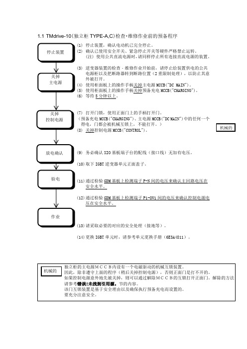
1.1 TMdrive-10(独立柜TYPE-A,C )检查・维修作业前的预备程序(1) 停止装置,确认电动机已完全停止。
(2) 确认已使用安全开关、紧急停止开关等硬件严格禁止运转。
(注) 使用公共直流电源时,请同样停止所有连接直流电源的装置。
(3) 逆变器装置的检查・维修作业开始前,请停止给装置供电的公共电源柜以及把断路器转到断路位置(2重限制处理),以防止其意外被打开。
(4) 使用柜面板上的操作手柄关掉主电源MCCB("DC MAIN")。
(5) 使用柜面板上的操作手柄关掉预备充电MCCB("CHARGING")。
(6) 等待5分钟以上。
(7) 打开门锁,使用正面门上的手柄打开门。
(预备充电MCCB("CHARGING")、主电源MCCB("DC MAIN")中的任何一个得电,门都会被机械互锁上,不能打开。
) (8) 关掉控制电源MCCB("CONTROL")。
(9) 务必确认XIO 基板端子台的配线(接口线)无加有电压。
(10) 取下IGBT 逆变器单元正面盖子。
(11) 通过检验GDM 基板上检测端子P-N 间的电压来确认主回路电压在安全水平。
(12) 通过检验GDM 基板上检测端子P1-OV1间的电压来确认控制电源电压在安全水平。
(13) 请采取必要的对应的安全处理(接地等)。
(14) 更换IGBT 单元时,请参考单元更换手册(6E3A4811)。
1.2 TMdrive-10(独立柜TYPE-A,C)恢复作业程序(电源投入程序)(1)在开电源之前,请确认是否已把主电源MCCB,预备充电MCCB,控制电源MCCB(“CONTROL”)关掉。
(2)请确认检查・维修作业时离线的地方以及更换的部品的恢复状态(如连接器的插入状态,导体的拧紧状态等)。
(3)把检查前转到断路位置的公共电源柜的断路器转到通常的位置(2重限制处理等解除)。
T-10A_Manual_C

注 意 (如果操作错误,预计仅会发生用户致残的危险及物理性损害的情形)
请勿使用本仪器指定以外的电池。并且 请勿将将新旧电池或不同型号的电池混 合在一起使用。在将电池安装在本仪器 上时,请按照本仪器的极性标志(+、-) 正确安装。否则会发生电池破裂及漏液, 导致火灾、受伤或污染周围环境。
请放置在离电源插座较近的地方,且电 源插头应能容易地拔插。
<保管方法>
● 本 仪 器 的 保 管 温 湿 度 范 围 为 - 20 ~ 55 ℃、 85%(相对湿度)以下(35℃时)。保管场所 请避开高温多湿的有结露危险的地方。如与干 燥剂一同保管在常温附近则更好。
●如放置在汽车的后窗下及后备箱内,在炎热天 气下会升至极高温,有可能引起故障或变形, 请勿将本仪器放置在这样的场所。
● 基本操作 ● ...............................................................................................................................7 预先准备 ...................................................................................................................................................................................................8 测量照度................................................................................................................................................................................................12 测量照度差值 / 照度比...................................................................................................................................................................13 测量积分照度......................................................................................................................................................................................16 自动积分停止功能............................................................................................................................................................................17 使用外部电源操作仪器..................................................................................................................................................................19
摩克(Moxa)TN-5305系列EN501555-口IP67无管理Ethernet开关产品介绍说明

TN-5305SeriesEN501555-port IP67unmanaged Ethernet switchesFeatures and Benefits•10/100BaseT(X),4-pin M12(D-coded),F/H duplex mode,and auto MDI/MDI-X connection•IP67-rated housing protection•Power input:12to45VDC,18to30VAC•Complies with all EN50155mandatory test items1•-40to75°C operating temperature range(-T models)CertificationsIntroductionThe TN-5305Series Ethernet switches are IP67-rated for tough industrial applications.By using M12connectors,you can rest assured that Ethernet cables will connect tightly to the switch,and will be robust enough to protect your applications from external disturbances,such as the vibration and shock encountered in the transportation industry.The space-saving TN-5305switches can be mounted virtually anywhere,and wide operating temperature(-40to75°C)models are also available for use in the most extreme weather conditions.TN-5305Series Ethernet switches comply with a portion of EN50155specifications,covering operating temperature,power input voltage,surge,ESD,and vibration,making the switches suitable for a variety of industrial applications.SpecificationsEthernet Interface510/100BaseT(X)Ports(M12D-coded4-pin femaleconnector)Standards IEEE802.3for10BaseTIEEE802.3u for100BaseT(X)IEEE802.3x for flow controlPower ParametersInput Current0.1A@24VDC,0.08A@36VDCInput Voltage18to30VAC(47to63Hz)24to36VDCNo.of Power Inputs1Operating Voltage18to30VAC12to45VDCPower Connector M12A-coded male connectorPhysical CharacteristicsHousing Plastic top cover,metal bottom plateIP Rating IP671.This product is suitable for rolling stock railway applications,as defined by the EN50155standard.For a more detailed statement,click here:/doc/specs/EN_50155_Compliance.pdfDimensions60x125x29.6mm(2.36x4.92x1.09in) Weight Packaged:270g(0.56lb)Installation DIN-rail mounting(with optional kit)Wall mountingEnvironmental LimitsOperating Temperature TN-5305:-25to60°C(-13to140°F)TN-5305-T:-40to75°C(-40to167°F)Storage Temperature(package included)-40to85°C(-40to185°F)Ambient Relative Humidity5to95%(non-condensing)Altitude2000mStandards and CertificationsFreefall IEC60068-2-32EMC EN55032/35EMI CISPR32,FCC Part15B Class AEMS IEC61000-4-2ESD:Contact:6kV;Air:8kVIEC61000-4-3RS:80MHz to1GHz:20V/mIEC61000-4-4EFT:Power:2kV;Signal:2kVIEC61000-4-5Surge:Power:2kV;Signal:2kVIEC61000-4-6CS:10VIEC61000-4-8PFMFEnvironmental Testing IEC60068-2-1,EN50155IEC60068-2-14,EN50155IEC60068-2-2,EN50155IEC60068-2-30,EN50155International Approval RCMRailway EN50121-4EN50155Railway Fire Protection EN45545-2Safety EN60950-1UL508Salt Spray Test IEC60068-2-11,EN50155Shock IEC60068-2-27,IEC61373,EN50155 Vibration IEC60068-2-64,IEC61373,EN50155 DeclarationGreen Product RoHS,CRoHS,WEEEMTBFTime3,451,678hrsStandards Telcordia SR332WarrantyWarranty Period5yearsDetails See /warrantyPackage ContentsDevice1x TN-5305Series switch Installation Kit1x panel-mounting kit Documentation1x quick installation guide1x warranty card DimensionsOrdering InformationModel Name PoE,10/100BaseT(X)Ports,M12D-CodedFemale Connector10/100BaseT(X)Ports,M12D-Coded FemaleConnectorPower Input Input Voltage Operating Temp.TN-5305–5Single input 24/36VDC,18to30VAC-25to60°CTN-5305-T–5Single input 24/36VDC,18to30VAC-40to75°CAccessories(sold separately)CablesCBL-M12(FF5P)/OPEN-100IP67A-coded M12-to-5-pin power cable,IP67-rated5-pin female M12connector,1m CBL-M12D(MM4P)/RJ45-100IP67M12-to-RJ45cable,IP67-rated,1mCBL-M12DMM4PM12DMM4P-BK-100-IP67M12-to-M12Cat-5E STP Ethernet cable,4-pin D-coded M12connector,IP67,1m ConnectorsM12D-4PMM-IP67M12D-coded connector,QUICKON type,4-pin male,IP67M12D-4P-IP68D-coded screw-in sensor connector,male,IP68M12A-5P-IP68A-coded screw-in sensor connector,female,IP68,4.05cmM12Connector CapsA-CAP-M12F-M Metal cap for M12female connectorA-CAP-M12M-M Metal cap for M12male connectorDIN-Rail Mounting KitsDK-M12-305DIN-rail mounting kit for EDS-305-M12©Moxa Inc.All rights reserved.Updated May17,2023.This document and any portion thereof may not be reproduced or used in any manner whatsoever without the express written permission of Moxa Inc.Product specifications subject to change without notice.Visit our website for the most up-to-date product information.。
LEMO连接器样本

PHW PUW
浮动式插座,带线夹,配短护套
尺寸 (mm) 线缆外径
˜L
产品编号
线缆组
外壳材料 L S1 Max Min
ø 23
PHW.3K.93C.CLCT96Z
2-4
105 15 9.5 8.9 黄铜镀铬
PHW.3K.93C.CLCT12Z
3
139 20 12.5 11.6
S1
注:短护套需另外订购。(见第8页)
外壳材料
FXW.3K.93C.CLM FXW.3K.93C.TLM准F2母光纤插芯PSS.F2.BA2.LCT10需另外订购。
2
FMW EDW
固定式插头,带圆法兰(4个螺丝固定),带线夹,配短护套
ø 22.5 ø 38
˜101 ˜71
10
S 15
产品编号
线缆组
线缆外径 Max Min
外壳材料
ø 3.4
EDW.3K.93C.CLC
黄铜镀铬
EDW.3K.93C.TLC
不锈钢
ø 18 ø 23
注:两个标准F2公光纤插芯FFS.F2.BA2.LCT10需另外订购。
外壳材料
黄铜镀铬 不锈钢
EBW 固定式插座,前端带方法兰(4个螺丝固定)
29 23
ø 3.4
ø 23 ø 23
42.5
3
3
产品编号
多芯系列
18
同轴以及混装系列
20
3K.93C 系列高清电视连接系统 HDTV 高清电视光纤连接器全球标准
瑞士雷莫(LEMO)在高清电视(HDTV)引入早期就开发 了 3K.93C 系列连接器,并使之成为了高清电视的连接 标准。目前在全球应用的连接器中,是唯一能完全匹配 SMPTE、ARIB 和 EBU 标准的连接器。具有超过 2 万次 插拔使用寿命,且性能优越,插入损耗仅 0.1dB 。LEMO 3K.93C 系列连接器被各个国内外知名的转播公司作为 高清摄像系统的标准接口。
MENNEKES插头说明书

阿根廷
比利时
丹麦
德国
芬兰
法国
英国
意大利
加拿大
克罗地亚
荷兰挪威奥地利来自波兰俄国瑞典
瑞士
斯洛伐克
西班牙
南非
捷克
匈牙利
美国
中国
3
MENNEKES — 全世界高品质的保证
创造连接
在德国基尔兴洪登姆/萨尔兰得总部,德国东部新乡/萨克索尼和南京/中国等三个生产 基地,曼奈柯斯生产制造符合国际市场需求的接插装置。我们的产品通过地区办事处, 子公司和代理商等途径遍布全球。 拥有600多名专业人员和一流的技术,我们确信曼奈柯斯产品享誉世界。
用于全世界的接插装置
Plugs for the world
中德合资南京曼奈柯斯电器有限公司
Sino-German Joint Venture Nanjing Mennekes Electric Appliances Co., Ltd.
中文版本
Chinese Edition
2
具有曼奈柯斯标志的产品是值得信赖的产品
为了达到高质量目标,我们通过并运行了符合DIN EN ISO 9001:2000标准的国际质量管理体系。作为以出 口为导向的企业,曼奈柯斯还获得了以下相关领域的国际机构的产品认证。
DMT
国际认证证书
曼奈柯斯的接插装置符合相关国家和国际标准。由于一些特殊的国家标准,并不是每一个产品都能 接受国际认证。
4
保持连接
德国东部新乡工厂
南京工厂
只有通过严格检验的产品,才能具有曼奈柯斯的名称。 我们的产品经过试验室里的剧冷、高热、防尘和浸水等在极端条件下的反复测试之 后,根据国际标准,获得了权威机构的认证。
5