三洋U52V超低温冰箱手册
冻干前后红细胞血型及生物活性指标的检测

冻干前后红细胞血型及生物活性指标的检测吴学忠;刘忠;吕蓉;李敏;李素萍;於娟;赵丹【摘要】目的检测冻干前、后红细胞血型抗原及其生物学活性,了解冻干前、后红细胞血型抗原及其生物学活性的变化情况.方法红细胞血型抗原的检测采用血型血清学方法,2,3-DPG和ATP用ELISA法.结果在ABO、Rh、MNSs、Kell、Duffy、P血型抗原中,冷冻前、冻干后红细胞血型抗原一致;在Lewis血型抗原中,冷冻前、冻干后红细胞血型抗原有变化.冷冻前、冻干后红细胞2,3-DPG和ATP含量均无明显变化.结论冷冻前、冻干后红细胞Lewis血型系统中的Lea和Leb血型抗原变化有明显差异;冷冻前、冻干后红细胞2,3-DPG和ATP含量变化无统计学意义.%Objective To detect the blood group antigens, the levels of 2,3-DPG and ATP of red blood cells (RBCs) before and after freeze-drying. Also the changes of blood group antigens and biological activity of RBCs beforeand after RBCs freeze-drying was observed. Methods The blood group antigens of RBCs were detected by the blood group serology, the levels of 2,3-DPG and ATP were detected by ELISA. Results The blood group antigens of RBCs were the same as before and after freeze-drying about ABO, Rh, MNSs, Kell, Duffy and P blood group systems. But the blood group antigens of RBCs of Lewis blood group systems were different before and after freeze-drying. The levels of 2,3-DPG and ATP of RBCs before and after freeze-drying didn't change significantly. Conclusion The Lea and Leb blood group antigens of RBCs before and after freeze-dryingof Lewis blood group systems have changed significantly. The levels of 2,3-DPG and ATP of RBCs before and after freeze-drying havn't chenged significantly.【期刊名称】《临床输血与检验》【年(卷),期】2011(013)004【总页数】4页(P316-319)【关键词】冷冻干燥;红细胞;血型;生物活性【作者】吴学忠;刘忠;吕蓉;李敏;李素萍;於娟;赵丹【作者单位】230031 安徽省合肥市中心血站;230031 安徽省合肥市中心血站;230031 安徽省合肥市中心血站;230031 安徽省合肥市中心血站;230031 安徽省合肥市中心血站;230031 安徽省合肥市中心血站;大连医科大学检验医学院【正文语种】中文【中图分类】R318.52;R331.1+41真空冷冻干燥保存是一种理想的红细胞保存方法,但该技术尚处于实验探索阶段。
松下 型号MDF-U73V超低温冰箱 维修手册说明书

Fan motor accumulation time, none
Overload relay 䊶H stage side compressor is ceased when it detects 70C higher than filter sensor temperature. 䊶E10 and PV are displayed alternately. 䋨Buzzer sounds and remote
Evaporator
Condenser
Refrigerant
Refrigerant oil Power supply Weight Accessories Optional component
ç
Ultra-low Temperature Freezer
W1010 × D875 × H2010 (mm)
WARNING * You are requested to use RoHS compliant parts for maintenance or repair. * You are requested to use lead-free solder.
Effective models
Following units are effective in this manual.
MDF-U73VC
823 191 80
220V 60Hz
Contents
㩷㩷㩷㩷㩷㩷㩷㩷㩷㩷㩷㩷㩷㩷㩷㩷㩷㩷㩷㩷㩷㩷㩷㩷㩷㩷㩷㩷㩷㩷㩷㩷㩷㩷㩷㩷㩷㩷㩷㩷㩷㩷㩷㩷㩷㩷㩷㩷㩷㩷㩷㩷㩷
Comparison MDF-U73V with MDF-U72V ---------------------------------------
Sanyo DC潜入式多系统空调技术与服务手册说明书

NoticeCORRECTIONSERVICE FLASHPRODUCTION CHANGEADDED INFORMATIONREFERENCE NO. 700855-02FILE NO.Please add this notice to the TECHNICAL & SERVICE MANUAL listed below.For Parts or Service Assistance please contact your local Sanyo HVAC Contractor or DistributorUnited States: SCS, HVAC Solutions Web: Parts:********************.com Service:**********************.comCanada: Sanyo Canada Inc.Web: Parts/Service:**************.com4/10 Printed in JapanTECHNICAL & SERVICE MANUALOUTDOOR UNIT : CMH1972ACMH2472A CMH3172ADC INVERTER MULTI-SYSTEM AIR CONDITIONERDestination: North AmericaProduct Code No.1 852 356 131 852 356 091 852 356 10REFERENCE NO. 700855-02Capacity at 230V 19,100 BTU/h 23,200 BTU/h 30,600 BTU/hOutdoor Model No.CMH1972A CMH2472A CMH3172ACMH1972ACMH2472ACMH3172AFILE NO.••Items in particular which may cause death or serious injury to the service personnel if the work is not performed correctly,if not performed correctly.Important safety precautions are described for all items in both categories. Be sure to carefully follow all of them.• Symbol Indication:This symbol indicates items to which we need to pay attention.In this triangle, a definite precautionary item is described.:This symbol indicates the item to be prohibited.In or close to this circle, a prohibited item is described.This symbol indicates the items requiring special attention or instruction.In or close to this circle, a prohibited item is described.• After doing repair work, perform a test run to confirm that there are no abnormalities.At the same time, explain the precautions in use to the user.SAFETY PRECAUTIONSTable of Contents24678141718212447535962687172737478...........................................................................................................................................................................................................................................................................................................................................................................................................................................................................................................................................................................................................................................................................................................................................................................................................................................................................................................................................................................................................................................................................................................................................................................................................................................................................................................................................................................................................................................................................................................................................................................................................................................................................................................................................................................................................................................................................................................................................................................................................................................................PageTABLE OF CONTENTS APPLICABLE INDOOR UNITS 1. OPERATING RANGE 2. SPECIFICATIONS2-1. Unit Specifications 2-2. Major Component Specifications 2-3. Other Component Specifications 3. DIMENSIONAL DATA 4. REFRIGERANT FLOW DIAGRAM4-1. Refrigerant Flow Diagram 5. PERFORMANCE DATA5-1. Temperature Charts 5-2. Cooling Capacity 5-3. Heating Capacity 6. ELECTRICAL DATA6-1. Electric Wiring Diagrams 7. FUNCTIONS7-1. Explanation of Functions 7-2. Protective Functions 8. TROUBLESHOOTING8-1. Precautions before Performing Inspection or Repair 8-2. Trouble Diagnosis by Error Monitop Lamps 8-3. Checking the Outdoor System 8-4. Trouble Diagnosis of Each Part 8-5. Trouble Diagnosis of Fan Motor7980818182848585A-1A-2............................................................................................................................................................................................................................................................................................................................................................................................................................................................................................................................................................................................................................................................................................................................................................................................................................................................................................................Page9. REFRIGERANT R410A:SPECIAL PRECAUTIONS WHEN SERVICING UNIT9-1. Characteristics of New Refrigerant R410A 9-2. Checklist before Servicing 9-3. Tools Specifically for R410A 9-4. Tubing Installation Procedures 9-5. In Case of Compressor Malfunction 9-6. In Case Refrigerant is Leaking 9-7. Charging Additional Refrigerant 9-8. Retro-Fitting Existing Systems APPENDIX A INSTALLATION INSTRUCTIONS APPENDIX B UNIT COMBINATION TABLESAPPLICABLE INDOOR UNITSCMH1972A CMH2472A CMH3172AMulti-Outdoor Unit Indoor Unit 3-Room 4-Room 4-RoomKMHS0772YES YES YESYES YES YESYES YES YESYES YES YESNO YES YESKMHS0972KMHS1272KMHS1872KMHS2472Wall Mounted TypeCMH1972A CMH2472A CMH3172AMulti-Outdoor Unit Indoor Unit3-Room 4-Room 4-RoomXMHS0972&PNR-XS1872YES YES YESYES YES YESYES YES YESXMHS1272&PNR-XS1872XHS1872&PNR-XS1872Semi-Concealed Type95 °F D.B. / 71 °F W.B.67 °F D.B. / 57 °F W.B.80 °F D.B. / 67 °F W.B. _ D.B. / _ W.B.1. OPERATING RANGEMaximum Minimum Maximum Minimum115 °F D.B. 14 °F D.B.75 °F D.B. / 65 °F W.B. 0 °F D.B.TemperatureIndoor Air Intake Temp.Outdoor Air Intake Temp.Cooling Heating2. SPECIFICATIONS2-1. Unit SpecificationsOutdoor Unit CMH1972A Indoor UnitKMHS0972 × 3Remarks:1.The values shown in performance section and electrical rating section above are based on the following unit combination.For other combination unit, please refer to the "Unit Combination Tables" in this manual. Indoor Unit : KMHS0972 3units Outdoor Unit : CMH1972A 1unit2.Rating conditions are:Cooling :Indoor air temp.80°F D.B./ 67°F W.B Heating :Indoor air temp.70°F D.B.Outdoor air temp.95°F D.B./ 75°F W.B.Outdoor air temp.47°F D.B./ 43°F W.B.< 230V >DATA SUBJECT TO CHANGE WITHOUT NOTICE.CompressorRefrigerant / Amount charged at shipment Ibs (g)Refrigerant Control( 11,600 to 24,800 )( 3.40 to 7.30 )6.71,5007.71,73519,1005.6024,8007.30( 9,800 to 19,100 )( 2.90 to 5.60 )Shipping VolumeCooling Heating16,3002,800Net ShippingPackage DimensionsWeightHeight × Width × Depth Height × Width × DepthIbs (kg)Ibs (kg)cu.ft (m 3)(mm)inch (mm)3-Room Multi Outdoor UnitOutdoor Unit inch --187 to 253D i m e n s i o n s & W e i g h tRefrigerant Tubing ConnectionsUnit DimensionsE l e c t r i c a l R a t i n gSensible Capacity Latent CapacityW Power Input V A Available Voltage Range Running Amperes Operation Sound (High) Cool / Heat Narrow tube Wide tube Refrigerant inch (mm)Tube Diameter inch (mm)143.3152.112.71(65.0)(69.0)(0.36)33-27/32 × 40-5/8 × 16-1/4(860 × 1,032 × 413)(740 × 900 × 320)Outdoor Unit29-1/8 × 35-7/16 × 12-19/321/4 (6.35) × 33/8 (9.52) × 3ft (m)dB-A Max. allowable tubing length per unit Flare Type 82 (25)R410A / 6.17 (2,800)Electric Expansion ValveDC Twin Rotary (Inverter)Fan Speeds Auto (Hi, Me, Lo)ControlMicroprocessor F e a t u r e s HSPFCompressor Locked Rotor Amperes BTU/Wh50 / 52BTU/h P e r f o r m a n c e-8.8%Power Factor 9898A 14.5TypeBTU/h kW Total CapacityBTU/h SEER BTU/Wh 16.4-3Number of Connectable Indoor Units 3Number of Operatable Indoor Units 230V Single-Phase 60HzVoltage Rating 1,707 (2,900)1,707 (2,900)Air Circulation (High)ft 3/min (m 3/h)COP W/W - 4.2EER BTU/h/W12.7-Fuse or Circuit Breaker CapacityA20Outdoor Unit CMH1972A Indoor UnitKMHS0972 × 3Remarks:1.The values shown in performance section and electrical rating section above are based on the following unit combination.For other combination unit, please refer to the "Unit Combination Tables" in this manual. Indoor Unit : KMHS0972 3units Outdoor Unit : CMH1972A 1unit2.Rating conditions are:Cooling :Indoor air temp.80°F D.B./ 67°F W.B Heating :Indoor air temp.70°F D.B.Outdoor air temp.95°F D.B./ 75°F W.B.Outdoor air temp.47°F D.B./ 43°F W.B.< 208V >DATA SUBJECT TO CHANGE WITHOUT NOTICE.CompressorRefrigerant / Amount charged at shipment Ibs (g)Refrigerant Control( 11,600 to 24,800 )( 3.40 to 7.30 )7.41,5008.51,73519,1005.6024,8007.30( 9,800 to 19,100 )( 2.90 to 5.60 )Shipping VolumeCooling Heating16,3002,800Net ShippingPackage DimensionsWeightHeight × Width × Depth Height × Width × DepthIbs (kg)Ibs (kg)cu.ft (m 3)(mm)inch (mm)3-Room Multi Outdoor UnitOutdoor Unit inch --187 to 253D i m e n s i o n s & W e i g h tRefrigerant Tubing ConnectionsUnit DimensionsE l e c t r i c a l R a t i n gSensible Capacity Latent CapacityW Power Input V A Available Voltage Range Running Amperes Operation Sound (High) Cool / Heat Narrow tube Wide tube Refrigerant inch (mm)Tube Diameter inch (mm)143.3152.112.71(65.0)(69.0)(0.36)33-27/32 × 40-5/8 × 16-1/4(860 × 1,032 × 413)(740 × 900 × 320)Outdoor Unit29-1/8 × 35-7/16 × 12-19/321/4 (6.35) × 33/8 (9.52) × 3ft (m)dB-A Max. allowable tubing length per unit Flare Type 82 (25)R410A / 6.17 (2,800)Electric Expansion ValveDC Twin Rotary (Inverter)Fan Speeds Auto (Hi, Me, Lo)ControlMicroprocessor F e a t u r e s HSPFCompressor Locked Rotor Amperes BTU/Wh50 / 52BTU/h P e r f o r m a n c e-8.8%Power Factor 9898A 14.5TypeBTU/h kW Total CapacityBTU/h SEER BTU/Wh 16.4-3Number of Connectable Indoor Units 3Number of Operatable Indoor Units 208V Single-Phase 60HzVoltage Rating 1,707 (2,900)1,707 (2,900)Air Circulation (High)ft 3/min (m 3/h)COP W/W - 4.2EER BTU/h/W12.7-Fuse or Circuit Breaker CapacityA20Outdoor Unit CMH2472A Indoor UnitKMHS0972 × 3Remarks:1.The values shown in performance section and electrical rating section above are based on the following unit combination.For other combination unit, please refer to the "Unit Combination Tables" in this manual. Indoor Unit : KMHS0972 3units Outdoor Unit : CMH2472A 1unit2.Rating conditions are:Cooling :Indoor air temp.80°F D.B./ 67°F W.B Heating :Indoor air temp.70°F D.B.Outdoor air temp.95°F D.B./ 75°F W.B.Outdoor air temp.47°F D.B./ 43°F W.B.< 230V >DATA SUBJECT TO CHANGE WITHOUT NOTICE.CompressorRefrigerant / Amount charged at shipment Ibs (g)Refrigerant Control( 11,600 to 29,200 )( 3.40 to 8.60 )9.02,04010.12,27023,2006.8029,2008.60( 9,800 to 23,200 )( 2.90 to 6.80 )Shipping VolumeCooling Heating19,6003,600Net ShippingPackage DimensionsWeightHeight × Width × Depth Height × Width × DepthIbs (kg)Ibs (kg)cu.ft (m 3)(mm)inch (mm)4-Room Multi Outdoor UnitOutdoor Unit inch --187 to 253D i m e n s i o n s & W e i g h tRefrigerant Tubing ConnectionsUnit DimensionsE l e c t r i c a l R a t i n gSensible Capacity Latent CapacityW Power Input V A Available Voltage Range Running Amperes Operation Sound (High) Cool / Heat Narrow tube Wide tube Refrigerant inch (mm)Tube Diameter inch (mm)143.3152.112.71(65.0)(69.0)(0.36)33-27/32 × 40-5/8 × 16-1/4(860 × 1,032 × 413)(740 × 900 × 320)Outdoor Unit29-1/8 × 35-7/16 × 12-19/321/4 (6.35) × 43/8 (9.52) × 3 + 1/2 (12.7) × 1ft (m)dB-A Max. allowable tubing length per unit Flare Type 82 (25)R410A / 6.17 (2,800)Electric Expansion ValveDC Twin Rotary (Inverter)Fan Speeds Auto (Hi, Me, Lo)ControlMicroprocessor F e a t u r e s HSPFCompressor Locked Rotor Amperes BTU/Wh50 / 52BTU/h P e r f o r m a n c e-8.4%Power Factor 9898A 14.5TypeBTU/h kW Total CapacityBTU/h SEER BTU/Wh 16.5-4Number of Connectable Indoor Units 4Number of Operatable Indoor Units 230V Single-Phase 60HzVoltage Rating 1,707 (2,900)1,707 (2,900)Air Circulation (High)ft 3/min (m 3/h)COP W/W - 3.8EER BTU/h/W11.4-Fuse or Circuit Breaker CapacityA20Outdoor Unit CMH2472A Indoor UnitKMHS0972 × 3Remarks:1.The values shown in performance section and electrical rating section above are based on the following unit combination.For other combination unit, please refer to the "Unit Combination Tables" in this manual. Indoor Unit : KMHS0972 3units Outdoor Unit : CMH2472A 1unit2.Rating conditions are:Cooling :Indoor air temp.80°F D.B./ 67°F W.B Heating :Indoor air temp.70°F D.B.Outdoor air temp.95°F D.B./ 75°F W.B.Outdoor air temp.47°F D.B./ 43°F W.B.< 208V >DATA SUBJECT TO CHANGE WITHOUT NOTICE.CompressorRefrigerant / Amount charged at shipment Ibs (g)Refrigerant Control( 11,600 to 29,200 )( 2.90 to 8.60 )10.02,04011.12,27023,2006.8029,2008.60( 9,800 to 23,200 )( 2.90 to 6.80 )Shipping VolumeCooling Heating19,6003,600Net ShippingPackage DimensionsWeightHeight × Width × Depth Height × Width × DepthIbs (kg)Ibs (kg)cu.ft (m 3)(mm)inch (mm)4-Room Multi Outdoor UnitOutdoor Unit inch --187 to 253D i m e n s i o n s & W e i g h tRefrigerant Tubing ConnectionsUnit DimensionsE l e c t r i c a l R a t i n gSensible Capacity Latent CapacityW Power Input V A Available Voltage Range Running Amperes Operation Sound (High) Cool / Heat Narrow tube Wide tube Refrigerant inch (mm)Tube Diameter inch (mm)143.3152.112.71(65.0)(69.0)(0.36)33-27/32 × 40-5/8 × 16-1/4(860 × 1,032 × 413)(740 × 900 × 320)Outdoor Unit29-1/8 × 35-7/16 × 12-19/321/4 (6.35) × 43/8 (9.52) × 3 + 1/2 (12.7) × 1ft (m)dB-A Max. allowable tubing length per unit Flare Type 82 (25)R410A / 6.17 (2,800)Electric Expansion ValveDC Twin Rotary (Inverter)Fan Speeds Auto (Hi, Me, Lo)ControlMicroprocessor F e a t u r e s HSPFCompressor Locked Rotor Amperes BTU/Wh50 / 52BTU/h P e r f o r m a n c e-8.4%Power Factor 9898A 14.5TypeBTU/h kW Total CapacityBTU/h SEER BTU/Wh 16.5-4Number of Connectable Indoor Units 4Number of Operatable Indoor Units 208V Single-Phase 60HzVoltage Rating 1,707 (2,900)1,707 (2,900)Air Circulation (High)ft 3/min (m 3/h)COP W/W - 3.8EER BTU/h/W11.4-Fuse or Circuit Breaker CapacityA20Outdoor Unit CMH3172A Indoor UnitKMHS0972 × 4Remarks:1.The values shown in performance section and electrical rating section above are based on the following unit combination.For other combination unit, please refer to the "Unit Combination Tables" in this manual. Indoor Unit : KMHS0972 4units Outdoor Unit : CMH3172A 1unit2.Rating conditions are:Cooling :Indoor air temp.80°F D.B./ 67°F W.B Heating :Indoor air temp.70°F D.B.Outdoor air temp.95°F D.B./ 75°F W.B.Outdoor air temp.47°F D.B./ 43°F W.B.< 230V >DATA SUBJECT TO CHANGE WITHOUT NOTICE.CompressorRefrigerant / Amount charged at shipment Ibs (g)Refrigerant Control( 11,600 to 32,000 )( 3.40 to 9.40 )12.32,80010.32,35030,6009.0032,0009.40( 9,800 to 30,600 )( 2.90 to 9.00 )Shipping VolumeCooling Heating25,8004,800Net ShippingPackage DimensionsWeightHeight × Width × Depth Height × Width × DepthIbs (kg)Ibs (kg)cu.ft (m 3)(mm)inch (mm)4-Room Multi Outdoor UnitOutdoor Unit inch --187 to 253D i m e n s i o n s & W e i g h tRefrigerant Tubing ConnectionsUnit DimensionsE l e c t r i c a l R a t i n gSensible Capacity Latent CapacityW Power Input V A Available Voltage Range Running Amperes Operation Sound (High) Cool / Heat Narrow tube Wide tube Refrigerant inch (mm)Tube Diameter inch (mm)180.8189.615.18(82.0)(86.0)(0.43)39-3/4 × 40-5/8 × 16-1/4(1,010 × 1,032 × 413)(890 × 900 × 320)Outdoor Unit35-1/32 × 35-7/16 × 12-19/321/4 (6.35) × 43/8 (9.52) × 2 + 1/2 (12.7) × 2ft (m)dB-A Max. allowable tubing length per unit Flare Type 100 (30.5)R410A / 8.38 (3,800)Electric Expansion ValveDC Twin Rotary (Inverter)Fan Speeds Auto (Hi, Me, Lo)ControlMicroprocessor F e a t u r e s HSPFCompressor Locked Rotor Amperes BTU/Wh53 / 52BTU/h P e r f o r m a n c e-9.3%Power Factor 9999A 17.0TypeBTU/h kW Total CapacityBTU/h SEER BTU/Wh 17.2-4Number of Connectable Indoor Units 4Number of Operatable Indoor Units 230V Single-Phase 60HzVoltage Rating 1,942 (3,300)1,807 (3,070)Air Circulation (High)ft 3/min (m 3/h)COP W/W - 4.0EER BTU/h/W10.9-Fuse or Circuit Breaker CapacityA20Outdoor Unit CMH3172A Indoor UnitKMHS0972 × 4Remarks:1.The values shown in performance section and electrical rating section above are based on the following unit combination.For other combination unit, please refer to the "Unit Combination Tables" in this manual. Indoor Unit : KMHS0972 4units Outdoor Unit : CMH3172A 1unit2.Rating conditions are:Cooling :Indoor air temp.80°F D.B./ 67°F W.B Heating :Indoor air temp.70°F D.B.Outdoor air temp.95°F D.B./ 75°F W.B.Outdoor air temp.47°F D.B./ 43°F W.B.< 208V >DATA SUBJECT TO CHANGE WITHOUT NOTICE.CompressorRefrigerant / Amount charged at shipment Ibs (g)Refrigerant Control( 11,600 to 32,000 )( 3.40 to 9.40 )13.62,80011.42,35028,6008.4032,0009.40( 9,800 to 28,600 )( 2.90 to 8.40 )Shipping VolumeCooling Heating24,2004,400Net ShippingPackage DimensionsWeightHeight × Width × Depth Height × Width × DepthIbs (kg)Ibs (kg)cu.ft (m 3)(mm)inch (mm)4-Room Multi Outdoor UnitOutdoor Unit inch --187 to 253D i m e n s i o n s & W e i g h tRefrigerant Tubing ConnectionsUnit DimensionsE l e c t r i c a l R a t i n gSensible Capacity Latent CapacityW Power Input V A Available Voltage Range Running Amperes Operation Sound (High) Cool / Heat Narrow tube Wide tube Refrigerant inch (mm)Tube Diameter inch (mm)180.8189.615.18(82.0)(86.0)(0.43)39-3/4 × 40-5/8 × 16-1/4(1,010 × 1,032 × 413)(890 × 900 × 320)Outdoor Unit35-1/32 × 35-7/16 × 12-19/321/4 (6.35) × 43/8 (9.52) × 2 + 1/2 (12.7) × 2ft (m)dB-A Max. allowable tubing length per unit Flare Type 100 (30.5)R410A / 8.38 (3,800)Electric Expansion ValveDC Twin Rotary (Inverter)Fan Speeds Auto (Hi, Me, Lo)ControlMicroprocessor F e a t u r e s HSPFCompressor Locked Rotor Amperes BTU/Wh53 / 52BTU/h P e r f o r m a n c e-9.3%Power Factor 9999A 17.0TypeBTU/h kW Total CapacityBTU/h SEER BTU/Wh 17.2-4Number of Connectable Indoor Units 4Number of Operatable Indoor Units 208V Single-Phase 60HzVoltage Rating 1,942 (3,300)1,807 (3,070)Air Circulation (High)ft 3/min (m 3/h)COP W/W - 4.0EER BTU/h/W10.9-Fuse or Circuit Breaker CapacityA20Outdoor UnitCMH1972A2-2-1. Outdoor UnitControl PCBControl Circuit Fuse ControlsPart No.Microprocessor 250V 25ACB-CMH1972A Pints (cc) -Micro F VACExternal FinishAcrylic baked-on enamel finishFV50S ... 1.91 (900)--Internal ControllerYes Yes Aluminum Plate Fin / Copper Tube218.1 Face Area ft 2 (m 2)6.40 (0.595) Coil RowsFins per inch Heat Exchanger CoilSIC-71FW-D490-1 (1)Compressor Oil ... Amount 890750 / 750OhmDC MotorTypeCompressor Model / Nominal Output CompressorCoil Resistance (Ambient Temp. 68 °F (20 °C))OhmDC Twin Rotary (Hermetic)5KD240XAB21 / 1,700W U - V :V - W :W - U :0.7200.7080.726CT (Peak current cut-off control)Compressor Discharge Temp. ControlOperation cut-off control in abnormal ambient Temp.Safety DeviceMicro F VACRun Capacitor Crankcase HeaterYes Yes Yes Overload RelayCS-7L-2515ModelOperation Temp.Open : 239 °F (115 °C), Close : 212 °F (100 °C)--230V 30W1 ... D18-1/8 (D460)FanPropellerQ'ty ... Dia.inch (mm)TypeTypeOver-Current Protection Over-Heat Protection(Ambient Temp. 68 °F (20 °C)) Fan MotorNominal Output Coil ResistanceSafety DeviceRough Measure RPM (Cool / Heat)Run Capacitor TypeModel ... Q'ty No. of PolesW 2-2. Major Component SpecificationsOutdoor Unit CMH2472AControl PCBControl Circuit Fuse ControlsPart No.Microprocessor 250V 25ACB-CMH2472A Pints (cc) -Micro F VACExternal FinishAcrylic baked-on enamel finishFV50S ... 1.91 (900)--Internal ControllerYes Yes Aluminum Plate Fin / Copper Tube218.1 Face Area ft 2 (m 2)6.40 (0.595) Coil RowsFins per inch Heat Exchanger CoilSIC-71FW-D490-1 (1)Compressor Oil ... Amount 890750 / 750OhmDC MotorTypeCompressor Model / Nominal Output CompressorCoil Resistance (Ambient Temp. 68 °F (20 °C))OhmDC Twin Rotary (Hermetic)5KD240XAB21 / 1,700W U - V :V - W :W - U :0.7200.7080.726CT (Peak current cut-off control)Compressor Discharge Temp. ControlOperation cut-off control in abnormal ambient Temp.Safety DeviceMicro F VACRun Capacitor Crankcase HeaterYes Yes Yes Overload RelayCS-7L-2515ModelOperation Temp.Open : 239 °F (115 °C), Close : 212 °F (100 °C)--230V 30W1 ... D18-1/8 (D460)FanPropellerQ'ty ... Dia.inch (mm)TypeTypeOver-Current Protection Over-Heat Protection(Ambient Temp. 68 °F (20 °C)) Fan MotorNominal Output Coil ResistanceSafety DeviceRough Measure RPM (Cool / Heat)Run Capacitor TypeModel ... Q'ty No. of PolesWOutdoor Unit CMH3172AControl PCBControl Circuit Fuse ControlsPart No.Microprocessor 250V 25ACB-CMH3172A Pints (cc) -Micro F VACExternal FinishAcrylic baked-on enamel finishFV50S ... 2.55 (1,200)--Internal ControllerYes Yes Aluminum Plate Fin / Copper Tube218.1 Face Area ft 2 (m 2)7.75 (0.72) Coil RowsFins per inch Heat Exchanger CoilSIC-71FW-D490-1 (1)Compressor Oil ... Amount 890800 / 750OhmDC MotorTypeCompressor Model / Nominal Output CompressorCoil Resistance (Ambient Temp. 68 °F (20 °C))OhmDC Twin Rotary (Hermetic)5JD420XAB22 / 3,000W U - V :V - W :W - U :0.4350.4410.452CT (Peak current cut-off control)Compressor Discharge Temp. ControlOperation cut-off control in abnormal ambient Temp.Safety DeviceMicro F VACRun Capacitor Crankcase HeaterYes Yes Yes Overload RelayCS-7L-2515ModelOperation Temp.Open : 239 °F (115 °C), Close : 212 °F (100 °C)--230V 30W1 ... D18-1/8 (D460)FanPropellerQ'ty ... Dia.inch (mm)TypeTypeOver-Current Protection Over-Heat Protection(Ambient Temp. 68 °F (20 °C)) Fan MotorNominal Output Coil ResistanceSafety DeviceRough Measure RPM (Cool / Heat)Run Capacitor TypeModel ... Q'ty No. of PolesWTemperature F ( C)403530252015105(-20)(-15)(-10)(-5)(0)(5)(10)(15)(20)-4514233241505968Resistance(kohm)3250688610412214015817619440608010012014016018020020Resistance(kohm)2-3. Other Component SpecificationsCMH1972A CMH2472A CMH3172A Sensor NameCompressor temp sensor TKS293BModel No.of sensor11Quantity of Sensor1 Outdoor air temp sensorOutdoor heat exchanger sensorAW / AN sensorBW / BN sensorCW / CN sensorDW / DN sensorTKS295BTKS292BTKS292BTKS292BTKS292BTKS292BModel No.of sensorSensor Name111 / 11 / 11 / 1Quantity of Sensor111 / 11 / 11 / 11 / 1111 / 11 / 11 / 11 / 1CMH1972A CMH2472A CMH3172A3. DIMENSIONAL DATAOutdoor Unit CMH1972AUnit: inch(mm)(852-0-0010-11200-0)Unit: inch(mm)(852-0-0010-20400-0)Unit: inch(mm)(852-0-0010-20300-0)Cooling cycle Heating cycleIndoor unitOutdoor unit4. REFRIGERANT FLOW DIAGRAM4-1. Refrigerant Flow DiagramOutdoor Unit CMH1972AInsulation of Refrigerant TubingBecause capillary tubing is used in the outdoor unit, both the wide and narrow tubes of this air conditioner become cold. To prevent heat loss and wet floors due to dripping ofcondensation, both tubes must be well insulated with a proper insulation material. The thickness of the insulation should be a min.5/16"(8 mm).After a tube has been insulated,never try to bend it into a narrow curve because it can cause the tube to break or crack.Thickness:Outdoor Unit CMH2472AInsulation of Refrigerant TubingBecause capillary tubing is used in the outdoor unit, both the wide and narrow tubes of this air conditioner become cold. To prevent heat loss and wet floors due to dripping ofcondensation, both tubes must be well insulated with a proper insulation material. The thickness of the insulation should be a min.5/16"(8 mm).After a tube has been insulated,never try to bend it into a narrowcurve because it can cause the tubeto break or crack.Thickness:Cooling cycleHeating cycleIndoor unit Outdoor unitCooling cycleHeating cycleIndoor unitOutdoor unitOutdoor Unit CMH3172AInsulation of Refrigerant TubingBecause capillary tubing is used in the outdoor unit, both the wide and narrow tubes of this air conditioner become cold. To prevent heat loss and wet floors due to dripping ofcondensation, both tubes must be well insulated with a proper insulation material. The thickness of the insulation should be a min.5/16"(8 mm).After a tube has been insulated,never try to bend it into a narrow curve because it can cause the tube to break or crack.Thickness:。
三洋科研医疗仪器产品说明书
血液保存箱
培养系统
MDF-U5411 MPR-214F / 414F / 414FS MPR-514 / 514R / 1014 / 1014R MPR-721 / 721R / 1410 / 1410R MBR-107D(H) / 506D(H) / 304D / 304DR / 304G / 304GR MBR-704G / 704GR / 1404G / 1404GR
家用空气净化器 ABC-VW24
商用空气净化器 VW-VF10BGC
电)。即买即用,而且充电完成后,即使在一年之后想用 时也能立即使用。
◎ 数码相机拍摄相片数量为干电池的4.4倍 eneloop比碱性干电池的电量更为持久。用数码相机拍摄 时,相片数量可达碱性干电池的4.4倍。除此之外,还可 用于遥控器和游戏机等,家庭中的各类使用电池的机器, 还可作为发生灾害时的备用电池,用途非常广泛。
◎ 抑制自然放电,即买即用 普通充电电池随着使用时间的变长,能量会逐渐减少, eneloop则大幅改善了一般充电电池的这一性质(自然放
印 该系列净化系统采用日常生活中的自来水配合三洋独
有的电解水技术实现洁净空气的目的。该系列产品针 对不同用户需求,开发商用及民用的专属型号,可为
司 日常生活提供安全与清新的空气。 公
2004
2005 2006
2007 2008
三洋医疗欧洲分部成立
技 术 特 点 提出GAIA概念
并入三洋能源与生态生物医疗部分,提出GAIA概念
贸 推出Cool Safe 压缩机技术
推出-150℃超低温保存箱MDF-C2156VAN -86℃超低温保存箱MDF-U53V/73V
国际 V.I.P. PLUS新技术的导入,推出全新V.I.P. PLUS技术的MDF-C8V(N)
福利特冰淇淋冰柜CVU300系列产品说明书

Installation, Operation and Service Manual801 Church Lane • Easton, PA 18040, USAOrder parts online Table of contentsWelcome to FollettFollett ice dispensers enjoy a well-deserved reputation for excellent performance, long-term reliability and outstanding after-the-sale support. To ensure that this dispenser delivers that same degree of service, we ask that you take a moment to review this manual before beginning the installation of the dispenser. Should you have any questions or require technical help at any point, please call our technical service group, (877) 612-5086 or+1 (610) 252-7301.Before you beginAfter uncrating and removing all packing material, inspect the equipment for concealed shipping damage. If damage is found, notify the shipper immediately and contact Follett Corporation so that we can help in the fi ling of a claim, if necessary.Check your paperwork to determine which model you have. Follett model numbers are designed to provide information about the type and capacity of Follett ice dispensing equipment. Following is an explanation of the different model numbers in the VU300 series.Specifi cationsElectricalEach dispenser requires a separate circuit with electrical disconnect within 10 ft (3 m). Equipment ground required. Standard electrical – 220 V, 60 Hz, 1 phase. Maximum dispenser fuse – 20 amps.M odel Dispensernumber amperageCVU300N series 2.2 ampsPlumbingDispenser3/4" PVC pipe nipple for bin drain3/4" PVC pipe nipple for drain pan drainWater connections1/4" ID plain water beverage hoseNote: Drains should be hard piped and insulated. Maintain at least 1/4" per foot (6 mm per 304 mm run) slope on drain line run.Water disconnect within 10 feet (3 m) of dispenser is suggested for automatic load units.Follett recommends use of a Follett water fi lter (part# 00130229) on ice machines connected to automatic fi ll dispensers.Ice machine Refer to detailed specifi cations in ice machine installation manual packed with ice machineDimensions and clearancesRequired clearances60" (1524 mm) minimum above counter for installation if dispenser will be dropped into counter 49" (1245 mm) minimum above counter for auger removal 12" (305 mm) minimum on ice chute side for service12" (305 mm) minimum on side opposite ice chute if ice transport tube enters this side 12" (305 mm) minimum between dispenser side(s) and optional ice machine(s)Side ViewFront View(shown with two Horizon™ HCC1000AVM RIDE™ Model Chewblet ® ice machines)(26 mm)InstallationInstalling dispenser in counterNote:All dispensers must be supported from below with supplied 4" – 6" (102 – 153 mm) adjustable leg accessory, or equivalent. Do not hang dispenser on fl ange.All dispensers must be installed level in both directions to ensure proper operation.1. Check that dispenser location meets all requirements in this manual and cut counter as shown below.2. Place support blocks in cabinet to raise dispenser to a height of 12" (305 mm).3. Place dispenser in counter onto support blocks.4. Attach adjustable legs to dispenser.5. Remove support blocks and lower dispenser feet to fl oor.6. Adjust legs for 1/8" (4 mm) clearance between dispenser lip and countertop to verify there is no load onfl ange.7. Apply a bead approximately 1/4" (6 mm) in diameter of NSF-listed silicone sealant (Dow Corning RTV-732 orequivalent) around perimeter of dispenser where it meets counter. Smooth sealant to a 1/8" (4 mm) radius.8. Install a PVC drain line with at least a 1/4" per foot (20 mm per 1 m) slope. Insulate drain line to preventcondensation.Note:Do not apply excessive heat if any sweating of fi ttings is necessary. Heat conduction through metal may melt threads in plastic drain.Do not reduce drain line size or tie drains together.9. Make electrical connections in accordance with applicable wiring diagrams provided. Provide disconnectswithin 10 ft (3 m) of dispenser and ice machine for servicing.Plan View – Counter cut-outField wiring diagramsNote:Field wiring diagrams are intended to aid electricians or technicians in understanding how equipment fi eld wiring must be installed in accordance with all local and NEC codes.works.AllOperationHow the dispenser worksFollett’s dispensers may be fed by Follett RIDE™ model ice machines or manually loaded (using ice from another source).In all models, ice is stored below the counter in the dispenser storage area. When the dispense lever or button is pushed, the dispense motors are activated. This causes the wheel assembly in the storage area to turn, moving iceInstalling optional auto-fi ll ice machine kit(s)Correct installation of RIDE model ice machine(s) is critical to proper performance of ice machine. Refer to installation manual packed with ice machine for important details on ice transport tube run, ventilation requirements and other installation requirements. Failure to comply with instructions may void warranty.To start and operate dispenser1. Follow detailed cleaning instructions in service manual before operating dispenser.2. For manual load units, remove front drain pan or rear lid and fi ll storage area with approved ice.Note: Follett manual load dispensers can accommodate most cube/cubelet ices up to 1" (26 mm) square, orFollett compressed nugget ice. Crushed, fl ake, bagged, nugget or congealed ice cannot be used. Use of these ices can jam dispenser and void warranty. Separate any “waffle-like” sections of cubes before adding to dispenser. For ice compatibility questions, please call Follett customer service at (877) 612-5086 or +1 (610) 252-7301.3. Turn power switch located on dispenser control box to ON position.4. For automatic fi ll units, follow detailed instructions in ice machine installation section of installation manual, then turn ice machine (bin signal) switch(es) located on dispenser control box to ON position and begin to make ice.5. When dispenser has at least 6" (153 mm) of ice in storage area, test operation.to the vertical auger assembly, which carries ice up to the dispense chute where it drops by gravity into the container. In units used with an optional ice machine accessory, ice is manufactured remotely and may be located up to 75 ft (23 m) away from the dispenser. Extruded ice is transported through a tube and pushed to the storage compartment of the dispenser. When the bin is fi lled, a bin thermostat shuts the ice machine off to avoid overfi lling the bin.CleaningUsing solutions below, clean and sanitize storage area and beverage lines before starting unit and on a routine basis as noted below.Note:Always disconnect power before cleaning dispenser.Do not run plastic parts through a dishwasher.Solution A:Prepare cleaning solution of 200 ppm of available chlorine content. Solution temperature must be +75 F – +125 F (+24 C – +52 C).Solution B:Prepare sanitizing solution of 50 ppm of available chlorine content. Solution temperature must be +75 F – +125 F (+24 C – +52 C).Recommended cleaning prior to start upCleaning ice storage area before use1. Refer to disassembly instructions (see Service section) and remove dispense wheel from ice storage area.2. Remove auger, auger tube and dispense mechanism.3. Wipe all components and ice storage area with cleaning Solution A.4. Rinse all components and ice storage area thoroughly with clear, potable water.5. Wipe all components and ice storage area with sanitizing Solution B.Recommended daily dispenser cleaning1. Remove all debris from drain pan.2. Pour 1 gallon (4 L) hot water into drain pan to keep drain lines clear.Recommended weekly dispenser cleaning1. Remove drain pan and grille and wash with Solution A. Rinse thoroughly.2. Pour a solution of one cup (8 oz/237 ml) household bleach mixed with one gallon (3.8 L) hot water intodrain pan to help prevent algae growth in drain lines.Recommended quarterly dispenser cleaning1. Remove top from dispenser and turn power switch to OFF position.2. Remove ice from storage area.3. Remove dispense chute cover, chute, auger motor assembly, auger and auger tube (see Service section).4. Remove drain pan, grille, dispense wheel, agitator rods, and drive shaft (see Service section).5. Clean all components and bin storage area with Solution A, rinse thoroughly with clear water and sanitizewith Solution B.6. Remove nozzles and diffusers from valves, soak for at least 10 minutes in cleaning Solution A, rinse,sanitize with Solution B and reinstall.Putting unit back in service after quarterly cleaning1. Reassemble components.2. For manual load units, fi ll unit with an approved ice (see important cautions on page 3).3. For RIDE models, turn bin signal switch(es) and dispenser power switch to ON position and allowstorage area to fi ll.4. Push dispense button or lever to test that dispenser is functioning properly.Recommended quarterly cleaning of optional auto-fi ll ice machine kit(s).Units equipped with optional ice machines require cleaning of ice machine system at least every six months, and more often if local water conditions dictate. Failure to clean ice machine system will result in decreased performance and potential damage to ice machine. Refer to Ice Machine Installation, Operation and Service Manual.ServiceDispense chute cover removal1. Remove top cover.2. Pull cover up and off to remove.3. On push button units, disconnect plug on harness. Auger motor assembly removal1. Remove drain pan.2. Remove thumbscrews from splash guard and remove.3. Remove thumbscrews from splash panel; lift and pullforward at base of panel and remove.4. Unplug auger motor at connector.5. Remove two 1/4-20 bolts holding auger motor to hold-down bracket.6. Remove two thumbscrews from auger motor stabilizerbracket and set aside.7. Lift auger motor off.Gate assembly removal1. Remove dispense chute cover and auger motor assembly.2. Remove thumbscrews on each side of clear focus chuteand remove.3. Remove quick release pin holding dispense gateassembly and chute.4. Lift gate up and over hinge tabs, then carefully pull and tiltto unhook from solenoid link.5. Pull ice chute toward you to unclip from dimples on chutemounting bracket.6. Pull ice chute and gate toward you and out through panelopening.7. Lift dispenser mechanism assembly off auger and augertube.Auger and auger tube removal1. Remove dispense chute cover and auger-motor assembly.2. Remove side panel of tower.3. Remove screw holding top auger tube ring to lower ring.4. Lift auger out of auger tube.5. Lift out auger tube, turning as needed to clear rivnuts onside auger motor mounting bracket.Dispenser wheel removal1. Remove dispenser top and turn power switch OFF.2. Remove all ice from bin.3. Remove drain pan and ice bin access cover below it.4. Remove splash guard and wheel motor access cover.5. Unplug wheel motor at connector and remove groundwire.6. Remove wheel motor by pulling out two quick releasepins.7. Lift drive shaft up through hole in countertop.8. Lift dispense wheel out through drain pan opening.Dispenser cutaway – front view Dispense chute assemblyFrontWiring diagramWHEEL MOTORL1BLACKPL1-2PL1-1P O W E RLIDBLACKGRAYR1DISPENSEPURPLE READYORG 47M T RPURPLE REDRED24V R E DCT1BROWN NOBROWNBR1TERMINAL STRIP CONNECTION PIN and SOCKET CONNECTIONPL2-1PL2-2L2M2M1BLK WHITE BLUEL 2AYELLOWYELLOW24V Y E LLEGEND:DISPENSE SOLENOIDR E DBLUE BIN T'ST A T2PL6-4DISPENSEPL6-2REDR196RED 1BROWNBLUE T -S T A TIM_#1PL4-3BLUEIM_#2SWITCH PL4-4YELLOWBROWNBR3A YELLOWREDPL6-1PL6-374R3WHITEBLACKWA TER DISPENSESOLENOIDWA TER DISPENSESWITCH S1DRAIN P AN SWITCHDISPENSE SWITCHLOWER COVERSWITCHDISPENSE RELAY AUGER MOTORPOWERSWITCH TOP LID SWITCHSAFETYSAFETY RELAY WHITEBLACK BLACKWHITEWHITEBLACKPURPLE BROWN240 VOLTS 24 VOLTSWHITEORGORG BIN SIGNAL PLUG - IM #1BIN SIGNAL PLUG - IM #2Dispenser troubleshooting guideBefore calling for service1. Check that ice is in the dispenser and that congealed cubes are not causing a jam.2. Check that circuit breaker and switches are in ON position.3. Check that drain pan and top are on securely. If ajar, dispenser will not operate. When the top is off, augerdoes not operate, even though the solenoids do.4. Check that all drains are clear.Note: For units equipped with Follett Chewblet ice auto-fi ll ice machine kit(s), see Ice Machine Operation and Service Manual for service and troubleshooting information.If problems persist after following this basic troubleshooting guide, call Follett’s technical service department at (877) 612-5086 or +1 (610) 252-7301.16271354108123119Replacement partsReference # Description Part #1 Lid, with graphics 009531412 Graphics, “Follett” 00116780 Not shown Cover, ice opening (below drain pan) 00143685 4 Drain pan, plastic 00196063 5 Grille, drain pan 00108845 Not shown Chute cover, dispense, push-button with switch, Ice 502440 Not shown Chute cover, dispense, push-button with switch, Water 502620 6 Chute cover, dispense, lever, Ice 502439 6 Chute cover, dispense, lever, Water 502619 7 Shield, drip (right hand) dispense 00984302 7 Shield, drip (left hand) dispense 00984377 8 Thumbscrew, 10/32-1/2, splash guard 501100 Not shown Switch, dispense, PB 502441 Not shown Switch, dispense lever (includes boot and spacer) 501714 Not shown Boot, dispense switch button, lever 501841 Not shown Lip kit (plastic strip bordering ice bin opening and adhesive) 502285 Not shown Insulation, transport tube (sold by the foot) 501176 Not shown Tube, ice transport, 10 ft 502522 Not shown Tube, ice transport, 20 ft 502523 9 Drain box 00155218 10 Bracket, drain pan locator 00143693 11 Bracket, drain box and pan locator 00155200 Not shown Magnet, drain pan 502888 Not shown Switch, magnetic reed 502887 12 Access panel, tower 00108407 13 Access panel, top 00953133Front ViewOrder parts online Dispenser Exterior12345689151110141312Reference #DescriptionPart #1 Motor, auger (includes capacitor), 100 RPM 009385552 Bracket, auger motor hold-down 502047 Not shown Bracket, auger motor stabilizer 00108498 Not shown Seal, shaft, auger motor 5019773 Auger 5019804 Auger tube (includes insulation) 5026315 Insulation, auger tube 5020996 Ring, auger tube, upper 5019397 Ring, auger tube, lower 5021558 Motor, wheel, Brother (includes capacitor) 001903069 Bracket, wheel motor 501981 Not shown Gasket, wheel motor bracket 501982 Not shown Pin, quick release, wheel motor (2 required) 502102 10 Drive shaft assembly 00126888 11 Agitator rod, fi xed 502629 12 Wheel, dispense 501978 13 Bearing plate, bottom auger 501971 Not shown Agitator rod, ramped 502628 Not shown Bracket, fi xed agitator (2 used per unit) 501974 Not shown Thumbscrew, 10/32 x 3/4, fi xed agitator bracket (2 required) 501259 14 T ee, drain 502059 15 Thermostat 500514 16 Bracket, ice hose and wheel motor 00126904 Not shown L eg 00137257 Not shown Coupling, auger top 00109306 Not shown Plug 2 lead, male, bin signal 502333 Not shown Socket 2 lead, female, bin signal502334Order parts online HopperReference # Description Part #1 Gate, dispense 5019552 Linkage pin, gate/solenoid 5020963 Pin, quick release, 3" (77 mm), gate and lever 5019494 Chute, ice 5019525 Solenoid 501961 Not shown Boot, solenoid 5020986 Dispense mechanism assembly 5019487 Spring, dispense mechanism (1 per side) 501950 Not shown Chute, focus 502459 Not shown Lever, dispense 501953Order parts online Dispense assemblyReference #DescriptionPart # 1 Transformer, 220 V/24 V 502885 2 Relay, dispense 501826 3 Strips, terminal502472 4 Switches (power and ice machine) 502209 5 Switch, safety502511 Not shown Switch, dispense, lever 502505 Not shown Thermostat, bin level 500514 Not shown Valve, solenoid, water502886 Not shown Fitting, outlet, 1/8" MPT x 3/8" OD tube 502562 Not shown Fitting, inlet, 1/8" MPT x 1/4" OD tube 502561 Not shownTube, water dispense, SS00947747Electrical componentsOrder parts online 801 Church Lane • Easton, PA 18040, USA Horizon, Maestro and RIDE are a trademarks of Follett CorporationChewblet and Follett are registered trademarks of Follett Corporation, registered in the US.。
甘油含量对冷冻干燥保存红细胞的作用

甘油含量对冷冻干燥保存红细胞的作用吴学忠;刘忠;吕蓉;李敏;李素萍;於娟;孙斌;王飞【摘要】目的分析甘油含量对冷冻干燥保存红细胞的作用.方法应用不同浓度甘油(5%、10%、20%、30%和40%)作为红细胞冷冻干燥保存的保护剂,研究冷冻干燥红细胞复水后红细胞形态以及复水后完整红细胞回收情况.结果甘油预处理的红细胞冷冻干燥后复水红细胞结构完整、形态正常,尤以40%甘油最佳,复水后红细胞回收率最高.结论研究为使用甘油作红细胞冻干保存的保护剂提供了初步的理论依据.【期刊名称】《临床输血与检验》【年(卷),期】2010(012)003【总页数】4页(P227-230)【关键词】冷冻干燥;红细胞;甘油【作者】吴学忠;刘忠;吕蓉;李敏;李素萍;於娟;孙斌;王飞【作者单位】230031,安徽省血液中心,合肥市中心血站;230031,安徽省血液中心,合肥市中心血站;230031,安徽省血液中心,合肥市中心血站;230031,安徽省血液中心,合肥市中心血站;230031,安徽省血液中心,合肥市中心血站;230031,安徽省血液中心,合肥市中心血站;230031,安徽省血液中心,合肥市中心血站;230031,安徽省血液中心,合肥市中心血站【正文语种】中文【中图分类】R318.52;R331.1+41目前红细胞的保存方法有4℃冰箱保存、-80℃冰冻保存及液氮深低温保存等,这些保存方法均未解决常温下长期保存红细胞的问题。
由于冻干制品在常温下性能稳定、便于运输,冷冻干燥保存技术已广泛应用于生物制品、药品和食品等长期保存。
真空冷冻干燥保存为一种理想的红细胞保存方法,但该技术尚处于实验探索阶段。
目前,多数文献是从低温保存方面进行红细胞冷冻干燥保存的研究,使用常见的低温保护剂[1,2],同时亦观察冷却速率及玻璃化作用、干燥条件及残余含水量等对细胞膜稳定性、蛋白质活性的影响[3-5]。
但实验可重复性差,红细胞实际回收率低。
甘油属渗透型保护剂,临床应用于红细胞的冰冻保存。
维vider NoFrost 7085 511-01 CNP 4056 无冻成分电子冰箱用户手册说明

Installation instructions.............................................................................................................................................. Page 20Operating instructions................................................................................................................................................... Page 14NoFrost combined refrigerator-freezerRead the operating instructions before switching on for the first timeInstallation instructions ................................................................................................................................................. Seite 8Adjustable storage shelvesAdjustable door racksType plate Disposal notesThe appliance contains reusable materials and shouldbe disposed of properly - not simply with unsortedhousehold refuse. Appliances which are no longerneeded must be disposed of in a professional andappropriate way, in accordance with the current localregulations and laws.When disposing of the appliance, ensure that the refrigerant circuitis not damaged to prevent uncontrolled escape of the refrigerantit contains (data on type plate) and oil.• Disable the appliance.• Pull out the mains plug.WARNINGplastic film!Do not allow children to play with packaging ma-terial. Take the packaging material to an officialcollection point.Range of appliance useThe appliance is suitable solely for cooling food ina domestic environment or similar. This includes,for example, use- in staff kitchenettes, bed and breakfast establish-ments,- by guests in cottages, hotels, motels and otherforms of accommodation,- in catering and similar services in the wholesaletrade.Use the appliance solely as is customary within a domestic envi-ronment. All other types of use are inadmissible. The applianceis not suitable for storing and cooling medicines, blood plasma,laboratory preparations or similar substances and products cov-ered by the 2007/47/EC Medical Devices Directive. Any misuseof the appliance may result in damage to or spoilage of storedgoods. Furthermore, the appliance is not suitable for operationin potentially explosive atmospheres.Bottle racktipping. This can lead to injury or property damage.Unscrew the additional adjustable foot on thesupport until it reaches the floor.Then turn it another 90°.ecodesign requirements will be available in the European productdatabase (EPREL). You can access the product database usingthe following link: https://eprel.ec.europa.eu/. You will be askedto enter the model identifier. You will find the model identifier onthe type plate.14ENSafety instructions and warnings• T o prevent injury or damage to the unit, the ap-pliance should be unpacked and set up by two people.• In the event that the appliance is damaged on delivery, contact the supplier immediately before connecting to the mains.• T o guarantee safe operation, ensure that the ap-pliance is set up and connected as described in these operating instructions.• Disconnect the appliance from the mains if any fault occurs. Pull out the plug, switch off or remove the fuse.• When disconnecting the appliance, pull on the plug, not on the cable.• Any repairs and work on the appliance should only be carried out by the customer service department, as unauthor i sed work could prove highly dangerous for the user. The same applies to changing the mains power cable.• Do not allow naked flames or ignition sources to enter the appliance. When transporting and cleaning the appliance ensure that the refrigerant circuit is not damaged. In the event of damage, make sure that there are no ignition sources nearby and keep the room well ventilated.• Do not stand on the plinth, drawers or doors or use them to support anything else.• This appliance can be used by children of 8 years old and over, and also by persons with restricted physical, sensory or mental capacity or lack of experience and knowledge, if they are supervised or have been instructed on safe use of the appli-ance and understand the resulting risks. Children must not be allowed to play with the appliance. Cleaning and user maintenance must not be carried out by children without supervision.• Avoid prolonged skin contact with cold surfaces or chilled/frozen food. T his could cause pain, numb-ness and frostbite. In the case of prolonged skin contact, protective measures should be taken, e.g. gloves should be worn.• Do not eat ice cream, particularly ice lollies or ice cubes, immediately after taking them from the freezer compartment as there is a risk of "burn-ing" because of the very cold temperatures.• Do not consume food which has been stored for too long, as it could cause food poisoning.• Do not store explosives or sprays using com-bustible propellants such as butane, propane, pentane, etc. in the appliance. Electrical com-ponents might cause leaking gas to ignite. Y ou may identify such sprays by the printed contents or a flame symbol.• Do not use electrical appliances inside the ap-pliance.• The appliance is designed for use in enclosed areas. Do not operate the appliance outdoors or in areas where it is exposed to splash water or damp conditions.• The LED light strips illuminate the interior of the appliance. They are not suitable for lighting a room.Climate ratingeration performance.type plate.The position of the type plate is shown inthe section entitled Description of the appliance. Climate rating Room temperatureSN +10°C to +32°CN +16°C to +32°CST +16°C to +38°CT +16°C to +43°CSN-ST +10°C to +38°CSN-T +10°C to +43°CDo not operate the appliance outside thespecified room temperature range.Setting up• Avoid positioning the appliance in direct sunlight or near cookers, radiators and similar sources of heat.• The floor on which the appliance stands should be horizontal and level. T o compensate for any unevenness, adjust the height••of 1 mused in your appliance is indicated on the type plate on the inside of the appliance.1516Switching the appliance on and offClean the interior of the appliance before switching it on for the first time (see "Cleaning ").To switch onPress the On/Off button (1) or (6) so that the temperature displays light up.To switch the refrigerator com-partment offPress the On/Off button (1) for ap -prox. two seconds.Note: If the freezer compartment (On/Off button (6)) is switched off, the entire appliance will beswitched off.Operating and control elements(1) On/Off button, refrigerator compartment (2) Alarm symbol (3) SuperCool button (4) SuperFrost button (5) SuperFrost symbol(6) On/Off button, freezer compartment (7) Ventilation button (8) Alarm button(9) Down setting button, freezer compartment (10) Freezer compartment temperature display (11) Up setting button, freezer compartment(12) Refrigerator compartment temperature display (13) Down setting button, refrigerator compartment (15) Up setting button, refrigerator compartment (16) Child-proofing symbol (17) Power failure symbol(18) Menu symbol > Setup mode is activated (activating thechild lock and adjusting the display brightness)(19) SuperCool symbolElectrical connectionOnly operate the appliance with alternating current (AC).The permissible voltage and frequency are indicated on the type plate. The position of the type plate is shown in the section entitled Description of the appliance .The socket must be properly earthed and protected by a fuse.The tripping current of the fuse must be between 10 A and 16 A.sion cable or extension socket.Setting the temperatureSetting the refrigerator temperatureWarmer temperature setting > press button (15)Colder temperature setting > press button (13)Setting the freezer temperatureWarmer temperature setting > press button (11)Colder temperature setting > press button (9)- While you are setting the tempera-ture, the temperature display will flash.buttons for the first time, the set temperature will be displayed.pressing the buttons again.- About 5 seconds after the button was last pressed the average inte-rior temperature will be displayed.Adjustable temperature ranges to 2°C.Temperature displayFactory setting = degrees FahrenheitChanging the temperature display to Celsius• Press the SuperFrost button (4) for about 5 seconds. Display =• Using the Up button (11) or Down button (9) select .• Press the SuperFrost button (4). Display =.• Press the SuperFrost button (4). Display =• Press the On/Off button (6).degrees Celsius.17ENBrightness of the temperature displayThe brightness is adjustable between 0 (no illumination) and5 (maximum brightness).• Press the SuperFrost button (4) for about 5 seconds. Display =• Using the Up button (11) or Down button (9) select .• Press the SuperFrost button (4).•press Up button (11).• T o make the display darker: press Down button (9).• Press the SuperFrost button (4).• The brightness is adjusted to the new value.• Press the On/Off button (6).Audible warning signalAudible door alarmIf an appliance door is left open for more than 180 seconds, the audible warning signal will sound. Press the audible warning on/off button back to standby when the door is shut.Audible/visual temperature alarmIf the temperature in the freezer compartment will sound and the alarm symbol (2) and the temperature display will flash.Press the audible warning on/off button (8) to cancel the alarm. The symbol (2) will stop flashing. The symbol (2) will disappear as soon as the temperature in the freezer compartment is low enough.This can be caused by:time, allowing warm ambient air to enter;• a long power failure;• a fault in the appliance.In each case, make sure food has not thawed or perished. If the alarm symbol does not go out, contact the customer service department (see section on Malfunctions).Child lockThe child lock is designed to protect the appliance from being switched off accidentally.Display =• Using the Up button (11) or Down button (9) select .• Press the SuperFrost button (4).When 1display:• T o activate the child lock, brieflypress the SuperFrost button (4).• The child lock symbol lightsup. flashes in the display.When0 is indicated in the display:• T o deactivate the child lock, briefly press the SuperFrost button (4).• The child lock symbol goes out.flashes in the display.• Press the On/Off button (6).Sabbath modeThis function complies with the religious requirements to be observed on the Sabbath or religious holidays.When Sabbath mode is activated, some of the functions of the control electronics are switched off.• The interior light remains switched off if one of the appliance doors is opened.• The interior fan remains in the status which is currently set (On or Off) if an appliance door is opened.• No door open alarm.• No temperature alarm.• Press the SuperFrost button (4) for about 5 seconds. Display = • Press the SuperFrost button (4).Display =• Press the SuperFrost button (4). Display =• Press the On/Off button (6).The sabbath mode is activated.Der Sabbat-Modus deaktiviert sich automatisch nach 120 Stun-den.Deactivating the sabbath mode• Press the SuperFrost button (4) for about 5 seconds. Display =• Press the SuperFrost button (4). Display = • Press the SuperFrost button (4). Display = • Press the On/Off button (6).The sabbath mode is deactivated.18large quantities of food are to be cooled rapidly.To switch on: Press the Super-Cool button (3) briefly > LED (19) lights up.Note:switches off automatically after about 6 hours.Cooling with fanWith the fan function switched on, a uniform temperature distribu-tion will be attained in the refrigerator compartment.This is recommended:- in high room temperatures (approx. 33°C or higher),- if the air humidity is high (e.g. during the summer).To switch onCooling(1) butter, cheese (2) eggs (3) bottles(4) baked goods, pre-cooked meals (5) (6) fruit, vegetables, salads (7) frozen food, ice cubesNotecontainers.Repositioning the door racks- Lift door rack vertically (1- By shifting the opening or closing the door.EquipmentYou can re-arrange the storage shelves as required.Lift the glass shelf, align the recess over the support and replace the shelf in a higheror lower position.Place the shelf rails provided, fig. 1, on the supports on the left and right at the desired height.Insert the glass shelves (1) and (2) as shown in fig. 2.If you need to make space for tall containers, simply slide the front half of the sectioned glass shelf carefully underneath the back half, fig. 2.If the cover is removed, do not look directly at the light through optical lenses from close distance. This can dam-age your eyes.Power failure display If appears in the display, the freezer temperature has risen too high due to a power failure.• Press the Alarm button (8).> The highest temperature during the power failure will be displayed.displayed.Do not eat perished food!Do not refreeze thawed food!Press the Alarm button (8) again to cancel the display.19ENMalfunctionsYou may be able to rectify the following faults by checking the possible causes yourself:• Appliance does not function:– Is the appliance switched on?– Is the plug correctly fitted in the mains socket?– Is the fuse intact?• Loud running noise:– Is the appliance set up firmly on the floor?– Does the appliance cause nearby items of furniture or objects to vibrate? Please note that noises caused by the refrigerant circuit cannot be avoided.• The temperature is not low enough:– Is the temperature setting correct (see "Setting the temperature")?– Have excessive amounts of fresh food been placed in the appli-ance? – D oes the separately installed thermometer show the correct reading?– I s the ventilation system working properly?– Iber ber type plate.Shutting your appliance downIf your appliance is to be shut down for any length of time, switch it off and disconnect the plug or switch off or unscrew the fuse. Clean the appliance and leave the door open in order to prevent unpleasant smells.The appliance complies with the relevant safety regulations and EU Directives 2014/30/EU and 2014/35/EU.CleaningBefore cleaning, always switch off the appliance. Disconnect from the mains or switch off or unscrew the fuse.• First clean the side panels with a conventional stainless steel cleaner. Subsequently, apply the enclosed stainless steel care product evenly onto the surfaces in the same direction in with they have been ground or polished.• Only clean the door surfaces with a clean and soft cloth. If nec-essary, moisten the cloth (water + detergent). Alternatively, use a micro-fibre cloth.- Do not use abrasive sponges or scourers, do not use concentrated cleaning agents and never use cleaning agents containing sand, chloride or acid or chemical solvents, as these would damage the surfaces and could cause corrosion.• Clean the inside and equipment parts with lukewarm water and a little detergent.Do not use steam cleaners because of the risk of injury and damage.• Ensure that no cleaning water penetrates into the electrical components or ventilation grille.• Dry all parts well with a cloth.• Do not damage or remove the type plate on the inside of the appliance. It is very important for servicing purposes.Freezingance .SuperFrostBy activating the SuperFrost function the temperature in the freezer compartment will drop to the lowest attainable value. Thus food up.• • hours.Y ou should not switch on the SuperFrost function:- when placing frozen food in the freezer,- when freezing up to approx. 2 kg fresh food daily.Notes on freezing and storage• Pack food which you are freezing yourself in quantities appropriate to your household. T o ensure that the food freezes right through, the following quantities should not be exceeded per package: fruit, vegetables: up to 1 kg, meat: up to 2.5 kg.• Pack frozen food in standard freezer bags or reuseable plastic, metal or aluminium containers.• Do not allow fresh food which is to be frozen to come into contact with food already frozen. Always keep packs dry in order to avoid them sticking together.• Always write the date and contents on the pack and do not exceed the stated storage time for the food.• Do not freeze bottles and cans which contain carbonated drinks as they might burst.• Only take out as much food as is immediately required for thawing. Use food which has been thawed in prepared meals as quickly as possible.Frozen food can be thawed in the following ways:- in a fan oven,- in a microwave oven,- at room temperature,- in the refrigerator.20Appliance dimensions The appliance can be used freestanding or semi built-in.If semi built-in, please consider the cabinet opening dimensions.Installation dimensionsIMPORTANTThe socket must not be situated behind the appli-ance and must be easily accessible.EN Unit ventingDo not restrict the air flow.installed in a soffit (3).IMPORTANTthe upper one.The section below the freezer door and the floormust not be covered.down until it has proper floor contact to support thehinge bracket.21Mounting the anti tipping deviceWARNING!Tip over hazard!The anti tipping brackets must be mounted to prevent the appliance from tipping when the fully stocked door is opened.IMPORTANTBe sure that there is no plumbing or electrical wiring located in this area which screws or drills could damage.1. Mark the center of the appliance on the back wall.2.Mount the anti tipping brackets within the given area.IMPORTANTThe screws for fastening the anti-tip device are not supplied with the appliance. Appropriate screws must be used for the material (wood, concrete, etc.) in which the safety device is mounted.Changing over door hingesDoor hinges should only be changed by a trained expert.1.the left.T op right2.3.the hinge.4.you.5.6.7.T op right8.9.door.22EN10.Tposite side.11.Topposite side.Bottom right12.13.Bottom right14.15.16.17.24Both doors32.the front and slide away.33. T plugs to the other side.Bottom of appliance 29. T ransfer cover plate to theopposite side.30. Screw hinge bracket intoplace.Bottom left31. using the adjustable foot.Centre left of appliance39. 34. T ransfer panels of bothdoor covers to the oppo-site side.Both doors 35.36.Bottom left40.50.least 90°.T op left51.52.Refrigerator door45.46.cable.Refrigerator door47.Refrigerator door48.sert hinge.49.Bottom left44.Click cover into place.insert pin.op leftdoor.op rightPlace the appliance in its finalat the place of installation.floor and then make a further25Liebherr Hausgeräte Lienz GmbHDr.-Hans-Liebherr-Strasse 1A-9900 LienzÖsterreich40。
Silver King 商业冰箱 SKF3 技术手册说明书
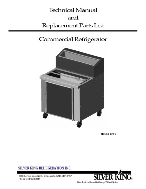
T echnical Manual and Replacement P arts List Commercial RefrigeratorMODEL SKF3TECHNICAL MANUALSILVER KING COMMERCIAL REFRIGERATORMODEL SKF3Thank you for purchasing Silver King food service equipment. Our goal is to provide our customers with the most reliable equipment in the industry today. Please read this manual and the accompanying warranty information before operating your new Silver King unit. Be sure to complete and mail the warranty card within 10 days of purchase to validate your warranty.INSPECT FOR DAMAGE AND UNCRATEUpon delivery of your new Silver King unit, uncrate at once to inspect for possible freight damage following the instructions printed on the exterior of the container. Report any damages to the carrier responsible for transportation and promptly present a claim for any evidence of mishandling. Save all packaging materials if a claim is filed.INSTALLATIONThe stainless steel exterior of the cabinet has been protected by a plastic covering during manufacturing and shipping. This covering can be readily stripped before installation. After removing this covering, wash the interior and exterior surfaces using a warm, mild soapy water solution and a sponge or cloth, rinse with clean water and dry.Legs/CastersThe unit comes with Legs or Casters. To install them, tilt the unit and thread the Legs or Casters into the 4 tapping plates in the bottom of the cabinet. Make sure that they are installed tightly to prevent future thread wear.Condenser Filter ScreenThe Condenser Filter Screen is installed on the unit. It is located underneath the compressor in a slot above the base.Cutting BoardThe Cutting Board is mounted on knobs installed on the front top surface of the cabinet.ShelvesInside the unit you will find Shelves and a plastic bag containing Shelf Supports. The Shelf Supports with the “tang” go on the rear Pilasters. This shelf system allows for easy adjustment to suit your needs.Door Adjustment and SwingShould the Door ever require straightening, loosen the Screws on the Hinges, square the Door with the cabinet and retighten the Screws.The mounting of the Door is easily reversible on single door units should space or convenience require that you do so. Simply remove the Screws holding the Hinges, rotate the Door 180 degrees and relocate the Hinges on the side opposite their original location.LocationWhen locating your new refrigerator, convenience and accessibility are important considerations, but the following installation guidelines must be followed;*Always avoid placing the refrigerator adjacent to an oven, heating element or hot air source that would affect the operation of the unit.*For proper ventilation the bottom front of the unit must not be obstructed. The unit must be on legs or casters to raise it off the floor. The unit can be installed tight on the sides and must have at least 4” of clearance in back.*The unit must be level or tilted backwards slightly.Electrical ConnectionsBe sure to check the data plate, located on the liner of the cabinet, for required voltage prior to connecting the unit to power. The specifications on the data plate supersede any future discussion.The standard refrigerator is equipped with an eight (8) foot power cord that requires a 115 Volt, 60 Cycle, 1 Phase properly grounded electrical receptacle. The power cord comes with a 3 prong plug for grounding purposes. Any attempt to cut off the grounding spike or to connect to an ungrounded adapter plug will void the warranty, terminate the manufacturers responsibility and could result in serious injury.The circuit must be protected with a 15 or 20 ampere fuse or breaker. The unit must be isolated on a circuit and not plugged into an extension cord.OPERATIONInitial start upAfter satisfying the installation requirements, the refrigerator is ready to start. The Compressor will start when the power cord is connected to the required power source. If the Compressor does not start when the unit is initially plugged in, check to make sure that the Temperature Control is not in the “off” position. Allow the unit to run for two hours before loading it with product. When loading the unit with product, take care not to block the air flow in the cabinet as this would affect the units performance. Temperature ControlThe Temperature Control is located on the back wall of the cabinet liner and is factory set to maintain an average cabinet temperature of approximately 36 to 40 Deg F. To obtain colder temperatures turn the Temperature Control stem clockwise and vice versa. Allow the unit a minimum of one hour to respond to a control setting adjustment.DefrostYour Silver King refrigerator is an automatic defrost unit and no additional plumbing is required. Automatic defrosting is accomplished when frost buildup on the Evaporator Coil is cleared during Compressor “off” cycles. Defrost water is collected in a pan located in the compressor compartment where it is evaporated into the room air. It is important that the unit be installed level to allow proper drainage of the defrost water.MAINTENANCEPreventative maintenance is minimal although these few steps are very important to continued operation and maximizing the life of the appliance.Cabinet SurfacesThe cabinet interior is aluminum and the exterior is stainless steel. These surfaces should be cleaned periodically with a solution of warm water and mild soap, rinsed and wiped dry with a soft cloth. A good stainless steel cleaner can also be used. Should a surface become stained, do not attempt to clean with an abrasive cleanser or scouring pad. Use a soft cleanser and rub with the grain of the metal to avoid scratching the surface. Do not use chlorinated cleaners. Always rinse well and dry after cleaning. CondenserPeriodically the Condenser Filter Screen must be cleaned. The Condenser Filter Screen is located on the bottom of the cabinet. To clean it simply pull it out the back of the unit and rinse it in a stream of water. Dry the screen by tapping it on a counter or floor. Replace the filter screen by sliding it back into its slot underneath the compressor. Do not operate the unit without the filter sreen installed!Door GasketThe Door Gasket will collect dirt and should be wiped clean with a warm, mild soapy water solution to extend its life and assure maximum cabinet performance and life.MODEL SERIAL NO. DATE INSTALLEDREPLACEMENT PARTS LIST – MODEL SKF3WHEN ORDERING REPLACEMENT PARTS, PLEASE PROVIDE MODEL AND SERIAL NUMBERS。
- 1、下载文档前请自行甄别文档内容的完整性,平台不提供额外的编辑、内容补充、找答案等附加服务。
- 2、"仅部分预览"的文档,不可在线预览部分如存在完整性等问题,可反馈申请退款(可完整预览的文档不适用该条件!)。
- 3、如文档侵犯您的权益,请联系客服反馈,我们会尽快为您处理(人工客服工作时间:9:00-18:30)。
注意:1. 未经三洋书面许可,不得以任何形式复制本手册的任何部分。
2. 本手册的内容如有变更,恕不另行通知。
3. 本手册如有任何不清楚之处或任何错误、遗漏之处,请与三洋联系。
SANYO Electric Biomedical Co.,Ltd. 版权所有日本付印目录安全操作预防措施P. 2使用注意事项P. 6 环境条件P. 7保存箱部件P. 8控制面板和键盘 P. 10安装安装场所 P. 11安装P. 12选购件温度记录仪 P. 13辅助冷却装置 P. 15独立内门P. 15保存架P. 16启动设备P. 17温度设定保存室温度P. 18键锁定功能P. 18 报警温度设定P. 19报警和安全功能 P. 20报警自动恢复时间设置P. 21远距离报警端子 P. 22设备状态监视 P. 23压缩机延时启动时间更改P. 24门报警延时时间更改P. 25日常保养清洁保存箱P. 26清洗冷凝器过滤网P. 26内壁除霜P. 27更换电池P. 27故障排除P. 28设备报废处理P. 28充电电池回收P. 29规格P. 30性能P. 32安全检查单P. 33安全操作预防措施本手册包括有重要的安全规定,请用户务必遵照执行。
这里所介绍的事项和规程旨在使你能正确安全地使用本设备。
如果遵照执行此处所述的预防措施,则将使用户和任何其他人免于可能发生的伤害。
“警告”和“注意”示意如下:如没有遵守警告标志下的事项,则有可能给人员带来危险,引发严重伤害或死亡事故。
注意关财产损失。
以下为标识的含意:该标识指注意。
该标识指禁止。
该标识指务必遵守的规定。
务必将本手册保存在本设备用户方便取用的地方。
< 设备上的标签>此标识被标注于高电压的电器罩盖上,用来防止触电意外的发生。
此电器罩盖只能由合格的工程师或维修服务人员移开。
工作场地的周围有没有良好的通风环境。
如果通风受到限制,则必须考虑采取其它的方法确保有一个安全的工作环境,这可能包含了空气监测和警告设备。
安全操作预防措施不得露天使用本设备。
当保存箱遭受雨水淋湿时,可能会导致漏电或触电事故。
只有合格的工程技术人员或维修人员才能安装本设备。
由不合格的人员安装可能会导致触电或火灾。
务必将本设备稳固地安放于坚实的地面上。
如果地面不牢固或安放场所不恰当,将导致设备翻倒或倾覆造成伤害。
不得将本设备安放于潮湿的场所或易遭受喷溅水的地方。
否则会因绝缘程度降低而引起漏电或触电等事故。
不得将本设备安装于存放有易燃或挥发性材料的地方。
否则将可能引起爆炸或火灾。
不得将本设备安装于有酸性或腐蚀性气体的地方。
否则会因腐蚀而引起漏电或触电。
请使用本设备铭牌上标明的专用电源。
务必将插头和电源插紧。
不正确的插入可能会引起火灾。
由合格的工程技术人员安装上接地线。
不得通过煤气、供水管、电话线或避雷针给本设备接地。
上述接地在管道线不完备的情况下会引起触电。
不得在本设备中存放挥发性或易燃性物品,否则有可能引发爆炸或火灾。
不得在本设备中存放易腐蚀的物品。
否则可能损坏设备内部组件或电气零件。
不得将诸如铁钉或铁丝之类的金属物件插入本设备的任何孔口和间隙或用于内部空气循环的任何排气口,否则会因上述物件与运动部件偶然接触而造成触电或受伤。
在存放有毒、有害或放射性物品时,请在安全区域使用本设备。
如使用不当可能会对人体健康或环境带来危害。
员受伤。
安全操作预防措施确保在维修保养时不会吸入设备周围的药物或悬浮粒,否则有可能对健康带来危害。
不得直接将水倾倒在设备上,否则会引起触电或短路。
用户不得自行拆卸、修理或改装设备。
如由未经授权的人员进行上述任何作业,则有可能因操作不当而引起火灾或人员受伤。
在不正常状态下继续运行有可能引起触电或火灾。
如果设备在无人监管的区域长时期闲置,则请确保小孩不会接近该设备且箱门不能完全关闭。
设备报废处置应由相应人员进行。
应将箱门拆除,以防止诸如窒息之类的事故发生。
当因辅助冷却系统而使用二氧化碳气体时,要注意房间内的空气流通。
空气中的二氧化碳浓度升高会有害身体健康。
在你通知要求对设备进行任何修理或维护作业时,为了维修人员的安全,请填写好《安全检查单》。
请选择一个平整且坚实的安装地面。
这一预防措施将防止设备翻倒、倾覆。
安装不当有可能因设备翻倒而引起漏水或人员受伤。
将设备与设备铭牌上标示的电源连接。
使用任何非铭牌标示的其他电压或频率的电源均有可能引起火灾和触电。
不得将自行捆绑,加工或是踩住供电的电线,也不要毁坏电源插头。
如果使用电线松动的插头可能会引起触电或因短路而引发火灾。
从电源插座拔下插头时,应握紧电源插头而不要去拉电源插头导线。
如果用手去拉导线则可能会引起触电或因短路而引发火灾。
不可用湿手接触诸如电源插头之类的任何电气零件或任何开关,否则可能引起触电。
安全操作预防措施在断电或者关闭电源后重新启动设备时,需要检查设置情况。
设置的改变可能会毁坏已保存过的项目。
不要将装有水的容器或重物放到设备上。
如果物品掉落,则可能引起人员受伤,而流出的水则会使绝缘程度降低引起漏电或触电。
不要攀爬到设备上或将物品放在设备上,否则会因设备翻倒而造成人员受伤或使设备受到损坏。
应握住把手关闭箱门,以免箱门夹住手指。
不要将玻璃瓶或者罐头装入箱体,因为这些可能会被冻裂而对人员造成伤害。
不要直接用手接触储存物品。
用手直接接触冰冻物件或者设备内壁可能会引起冻伤。
不要倚靠在门上。
以防碰到突起的部分或损坏的门而受伤。
修理时应戴上手套,以防碰到尖锐的边缘或转角而受伤。
注意检查手册中提到的过滤网,并且必须要进行清洗。
积满灰尘的过滤网会导致温度上升或故障。
当拿出过滤网进行清洗时,不要直接碰到冷凝器。
以防因表面的高温而受伤。
搬移设备之前,应拔下电源插头,务必不要损伤电源线。
电源线破损有可能导致触电或火灾。
在搬移设备期间,应注意不要让设备翻倒,以防设备受损或人员受伤。
电,漏电或火灾。
包装塑料袋不要放在小孩够得着的地方,因为塑料袋有可能引起窒息事故发生。
使用注意事项●当首次启动或长时间不用保存箱的时候,报警装置可能不动作,因为它的镍氢充电电池已经被完全放电了。
这并不意味出现故障。
在此情况下,让保存箱连续工作3小时左右。
要充足空电池,需要让保存箱持续运转2天左右。
●在环境温度较高的场合,保存箱首次启动运行之后,箱体外壳门框位置周围可能会发热。
然而这并非意味着发生故障。
这是因为为了防止在箱体外壳周围粘附冰霜,而在门框周围安装了热气管道的缘故。
●在把物品放进保存箱之前,先确认箱体内的温度已经充分下降,然后再分批放入物品以防其温度升高。
●超低温保存箱的数字式温度计是为显示保存室中间部位的温度而专门设计的。
虽然该温度计所显示的温度有时会稍稍高于保存室中央部位的实际温度,但是它会逐渐接近真实温度。
●保存箱后壁板上安装有一通孔,以便测试时引出箱内的测量电缆。
在引出测量电缆之后,务必重新装好孔盖和隔热材料,否则保存室的温度不能完全降下来,而且会导致通孔外侧的周边出现积霜。
●要一直轻开轻关箱门。
否则可能导致箱内的物品掉落,门关不严或会损坏门封条。
●使用稀释过的中性清洁剂清洁设备(未稀释的清洁剂会损坏塑料成份。
稀释的方法请参考清洁剂的说明书)。
不应使用刷子、酸、汽油、肥皂粉、抛光粉或热水清扫保存箱,因为上述材料有可能损伤涂漆表面与塑料橡胶零部件。
务必格外注意,不要用汽油之类的挥发性溶剂擦拭塑料橡胶零部件。
●保存箱运转时,在箱体内壁和内门上会出现霜。
可以用附带的铲子或其它相同的工具来除霜。
当大量的霜堆积在内门上时,内门将很难打开。
因此,请参照第27页上的关于内门除霜的内容。
●在内壁后面有很多冷却盘管,不要用小刀、冰凿或螺丝刀来除内壁的霜。
除霜时注意不要伤到内壁或者在内壁上划开口子,否则将导致设备故障。
同时要注意不要放置重物和带尖角边缘的物品在箱体底部。
环境条件本设备是按照下列条件设计的,至少在下列条件下运行是安全的(基于IEC 1010-1):1.室内使用;2.海拔高度不高于2000米;3.环境温度5℃~40℃范围内;4.温度不高于31℃时最大相对湿度为80%,随温度升高最大相对湿度呈线性降低,当温度升高至40℃时最大相对湿度50%;5. 主电源电压波动不超过额定电压的±10%;6. 由厂家规定的另外的电源电压波动范围;7. 符合设备安装等级(过电压等级)II的瞬态过电压;对于主电源而言,最低和普通等级为II级;8. 符合IEC664标准的污染等级II。
保存箱部件洁。
5. 测试用通孔(在后方的底部):它可用于通过测试用传感器,或者电线,或者辅助冷却装置通往箱体的喷嘴。
6. 内门:开关内门应迅速,从而使上升的温度达到最小。
关门时要完全锁上插销。
这扇门可以拆下来进行清洗或除霜。
参见第27页的“日常保养”。
7. 锁:将钥匙反时针旋转180度,便可锁定外箱门。
8. 控制面板(在外门的上端):用来显示温度设置和运行的情况。
参见第10页。
9. 小脚轮:为方便箱体搬移,安装了4个小脚轮。
安装设备时,务必调节水平支脚确保箱体前面的2个小脚轮脱离地面。
10. 水平支脚:保存箱的高度可以通过这一支脚来调节,在安装时可以保持保存箱的平衡。
11. 固定把手(在后侧):2个固定把手用以保持设备和墙壁之间的间距,另外固定把手还可用做设备的固定拴。
参见第12页的“安装”。
12. 进气口(隔栅):不要堵住这个口以便保持正常的冷却性能。
13. 电源开关:它可以打开或关闭保存箱的电源。
接通–“I ”关闭–“○”14. 温度记录仪安装隔间:一个自动温度记录仪(选购件) 可以安装在这里。
参见第13页的“温度记录仪”。
15. 过滤网(隔栅后部):这个过滤网可以防止在冷凝器上积灰。
积满灰的过滤网可能会导致制冷设备损坏。
需每月清洗一次过滤网。
参见26页“日常保养”中的过滤网清洗。
16. 电池开关:它是断电报警用电池。
通常情况下保持这个开关常开。
若保存箱长时间不运转时,请关闭此开关。
17. 远距离报警端子:用于将报警情况传送到远程位置。
参见第22页的“远距离报警端子”。
18. 安装选购件的隔间位置:保存箱部件1. 蜂鸣器停止键(BUZZER): 按下该键,报警声将停止。
但在报警测试中按下此键不能停止报警声。
2. 设定键(SET):按下该键进入设置温度的模式,同时数字键闪烁。
再按下此键,设置就被保存了。
如果在设置模式中90秒内没有再按键,则会自动返回温度显示状态。
参见第18页的详细内容。
3. 数位移动键( ): 在设置模式下按下该键可使数位移动。
在显示温度状态下按住此键超过5秒则进入键锁定状态。
参见第18页的详细内容。
4. 数值增加键( ): 在设置模式下按下该键可使数值增加。
在键锁定状态下按下此键则可以选择键锁定的开或关。
在显示温度状态下按住此键超过5秒则进入设置报警温度和设置报警自动恢复时间状态。