自脱离三相组合式过电压保护装置说明书(SHK-BOD)
三相电源4杆可拔电路保护器产品说明书
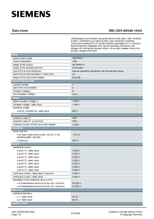
● at 415 V / rated value
● at 500 V / rated value
● at 690 V / rated value
breaking capacity maximum short-circuit current (Icu)
● at 415 V / rated value
● at 500 V / rated value
number of NC contacts / for auxiliary contacts
number of NO contacts / for auxiliary contacts
Suitability
suitability for use
Product details
product component
● at 690 V / rated value
Connections
arrangement of electrical connectors / for main current circuit
type of electrical connection / for main current circuit
Current operational current ● at 40 °C / rated value ● at 45 °C / rated value ● at 50 °C / rated value ● at 55 °C / rated value ● at 60 °C / rated value ● at 65 °C / rated value ● at 70 °C / rated value continuous current / rated value / maximum continuous current / rated value adjustable current response value current ● of instantaneous short-circuit trip unit / minimum ● of instantaneous short-circuit trip unit / maximum
SHK-BOD自脱离过电压保护器
BOD(保的)R自脱离过电压保护装置产品型号:SHK-BOD由于过电压能量过大、超期服役、产品质量等原因造成过电压保护器和避雷器的氧化锌阀片烧毁,并导致相间短路的事故时有发生。
由于对截面选择、电缆长度、线间距离处理不当,全密封结构过电压保护器的引线电缆没能有效发挥安全脱离的作用。
大量的事故致使对过电压保护器和氧化锌避雷器失去信息,一些用户拆除现有安装使用的过电压保护器,少数用户拒绝在中压配网装设过电压保护器和氧化锌避雷器。
为解决三相组合式过电压保护器的安全自脱离问题,我公司利用自主知识产权的过电压保护器脱离技术,专门开发出BOD型自脱离过电压保护器,于2009年获得了国家发明专利(ZL 2009 1 0116080.6)和实用新型专利(ZL 2009 2 0142756.4)。
产品用途:●装设在进出线开关柜的线路侧,可有效限制电网的内部过电压和真空开关开断过程中发生在线路侧的操作过电压;●装设在电压互感器柜,可有效限制电网的内部过电压和真空开关开断过程中发生在电源侧的操作过电压。
产品功能:●能有效限制发生在相与地之间和相与相的大气过电压和电网的各类内部过电压。
●具有动作计数和脱离器状态监测功能。
●配置RS—485通讯接口,可通过网线与监控系统实现数据远传。
装置特点:●采用放电间隙与氧化锌阀片串联作为基本保护单元,巧妙地解决了用于中性点非有效接地系统的避雷器和过电压保护器普遍存在的限制过电压与自身安全的矛盾。
●串联间隙与氧化锌阀片在参数方面的巧妙配合,两者互为保护,无间隙、无续流,动作寿命至少可达10000次。
●采用四星型对称结构,相间保护特性与相对低保护特性相同,更有利于保护相间绝缘。
●采用阻性放电间隙,大大降低了冲击系数。
●当氧化锌氧化锌阀片崩溃后脱离器可在1~2ms之内可靠动作,可有效避免氧化锌阀片烧毁导致的相间短路事故。
SHK-TBP三相组合式过电压保护器

三相组合式过电压保护器产品型号:SHK-TBP6~35kV中压系统,随着真空断路器的大量采用产生操作过电压更加频繁,线路电缆化使得弧光接地过电压明显提高。
中压电网普遍采用的交联电缆等固体绝缘设备,在操作过电压、弧光接地以及铁磁谐振过等电网内部电压长期持续的积累性破坏下,绝缘事故频繁发生。
除了对雷电过电压进行有效防护之外,对发生在相对地和相与相之间的各种内部过电压也必须采取有效地限制措施,以大幅度地延长固体绝缘设备的运行寿命。
为此有效的限制相间和相对地的各类过电压,我公司开发了SHK-TBP型三相组合式过电压保护器,曾于1993年获得国家专利(ZL93 2 03502.7),并于2009年再次获得实用新型专利(ZL 2009 2 0142758.3)产品用途:●装设在进出线开关柜的线路侧,可有效限制电网的内部过电压和真空开关开断过程中发生在线路侧的操作过电压;●装设在电压互感器柜,可有效限制电网的内部过电压和真空开关开断过程中发生在电源侧的操作过电压。
产品功能:●能有效限制大气过电压以及发生在相与地之间的各类过电压;●能有效限制发生在相与相之间的各类过电压;●可按用户要求配置动作计数功能。
●软连接的引线电缆可作为自动脱离器,防止阀片烧毁之后引起相间短路事故。
产品特点:●采用放电间隙与氧化锌阀片串联作为基本保护单元,巧妙地解决了用于中性点非有效接地系统的避雷器和过电压保护器普遍存在的限制过电压与自身安全的矛盾。
●串联间隙与氧化锌阀片在参数方面的巧妙配合,两者互为保护,无间隙、无续流,动作寿命至少可达10000次。
●采用四星型对称结构,相间保护特性与相对低保护特性相同,更有利于保护相间绝缘。
●采用特殊配方和特殊工艺烧制的“瓷环”作为放电间隙,冲击系数等于1,保护特性不受过电压频率和波形的影响,保护性能稳定。
●采用硅橡胶外套和外引高压电缆的全密封结构,保护性能不受外界环境条件的影响,可方便地直接安装在开关柜的手车底盘上或互感器室内。
三相组合式过电压保护器产品说明书

三、型号说明
1.保护对象:J-电机;Z-变压器、母线线路、开关;R并联补偿电容器;
O-电机中性点;D-电缆保护器
2.使用环境:W为户外型,无‘W’只适用于户内;
3.附加功能:“J”动作计数器;“IM”过电压检测仪
四、技术参数
1 .用于电机、变压器、开关、母线、线路、电容器等设备过电压保护器。
三相组合式过电压保护器
(TBP-B-42/280)
使
用
说
明
书
醴陵代言电气有限公司
一、产品用途
三相组合式过电压保护器(TBP-B-42/280)是一种新型的过电压保护器,它主要应用于发电、供电和企业的用电系统中,对电机、变压器、开关、母线、电容器等电气设备,除了限制大气过电压保护外,同时也可限制电力系统的操作过电压,对相间和相对地的过电压,均能起到可靠的限制作用。
3、TBP-B-42/280在和三相电源(A、B、C)及接地端(D)相连时,须注意以下事项:
⑴电缆外端裸露的连接线鼻子相互之间距离,应满足不同电压等级的不同相带电导体之间保持的最小安全距离的要求;
⑵TBP-B-42/280电缆线之间的安全距离及TBP-B-42/280电缆线与不同相母线(或柜体)之间的安全距离应不小于该型保护器相间距离(应在电缆电缆拉紧状况下);
二、产品结构/特点
三相组合式过电压保护器(TBP-B-42/280)的电气原理如图一所示,图中FR为高能容氧化锌非线形电阻,JX为放电间隙,由于采用对称结构,其中任意三个可分别接入A、B、C三相,另一个接地线。
三相组合式过电压保护器(TBP-B-42/280)的主要特点:
1.通流容量大,适用范围更广;
2.采用四星形接法,可将相间过电压大大降低,保护的可靠性大为提高。
10KV三相组合式过电压保护器说明书
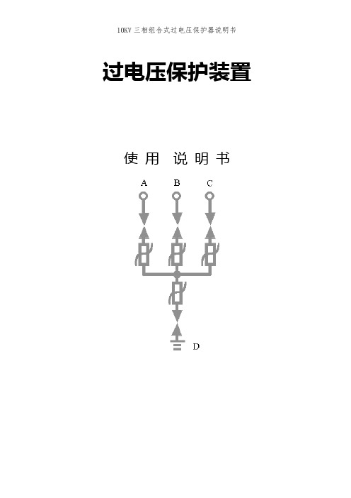
过电压保护装置使用说明书过电压保护装置使用说明一、产品用途三相组合式过电压保护器主要用于发电、供电和用电企业的电力电网中。
用来保护变压器、开关、母线、电动机等电气设备,可限制大气过电压及各种开关引起的操作过电压,对相间和相对地的过电压均能起到可靠的限制作用。
二、结构/特点三相组合式过电压保护器的电气原理如图(1)所示,图中FR为氧化锌非线形电阻,CG为放电间隙,由于采用对称结构,其中任意三个可分别接入A、B、C三相,另一个接地线。
三相组合式过电压保护器具有下面的一些特点:1.用氧化锌非线性电阻和放电间隙的结构,使两者互为保护。
放电间隙使氧化锌电阻的荷电率为零,氧化锌电阻的非线性特性又使放电间隙动作后无续流,放电间隙不再承担灭弧任务,提高了产品的使用寿命。
2.采用四星形接法,对相间和相对地的过电压均能起到可靠的限制作用。
可将相间过电压大大降低,保护的可靠性大为提高。
3.在各种电压波形下放电值均相等,不受各种操作过电压波形的影响,过电压保护值准确,保护性能优良。
4.使用环境温度为-400C~+600C,海拔高度小于2000m。
5. 本产品带脱钩装置,觉有防爆功能。
三、型号说明HB-BOD-□-□/□□-□附加功能使用环境相间距离(mm)持续运行电压(kV)保护对象1.保护对象:D-电动机 ;B-电站; R-并联补偿电容器; O-电机中性点;2.持续运行电压:允许持久地施加在相间及相对地的工频电压有效值;3.外套类型:F硅橡胶外套;4.使用环境:W为户外型,无‘W’只适用于户内;5.附加功能:“J”或“IM”为过电压动作记数器,(只适用于户内型);6.采用高压电缆外引结构,因此,对外引电缆长度“L”及线鼻子孔经“φ”要求,由用户在订货时注明。
四、技术参数表一型号保护对象保护器持续运行电压(kV)有效值保护对象额定电压(kV)有效值工频放电电压(kV)有效值高度mm有效值允许范围HB-D-7.6/131电动机7.66.3 12.48 11.25~15.0186200HB-D-12.7/131 12.7 10.520.6 18.0~25186235HB-B-7.6/131 变压器、母线、发动机、开关线路7.6 6 1412.6~17.5186 235HB-B-12.7/131 12.7 10 23.2 20.88~30.0186235五、外型尺寸图 (见附图)10KV等级以下图形六、试验方法及注意事项1、试验方法:试验原理接线如图(2)所示。
三相断路器三路锁定套件的说明书
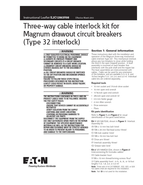
Three-way cable interlock kit for Magnum drawout circuit breakers (Type 32 interlock)I WARNING(1) ONLY QUALIFIED ELECTRICAL PERSONNEL SHOULD BE PERMITTED TO WORK ON THE EQUIPMENT.(2) ALWAYS DE-ENERGIZE PRIMARY AND SECONDARY CIRCUITS IF A CIRCUIT BREAKER CANNOT BE REMOVED TO A SAFE WORK LOCATION. (3) DRAWOUT CIRCUIT BREAKERS SHOULD BE LEVERED (RACKED) OUT TO THE DISCONNECT POSITION.(4) ALL CIRCUIT BREAKERS SHOULD BE SWITCHED TO THE OFF POSITION AND MECHANISM SPRINGS DISCHARGED.FAILURE TO FOLLOW THESE STEPS FOR ALL PROCEDURES DESCRIBED IN THIS INSTRUCTION LEAFLET COULD RESULT IN DEATH, BODILY INJURY, OR PROPERTY DAMAGE.i WARNINGTHE INSTRUCTIONS CONTAINED IN THIS IL AND ON PRODUCT LABELS HAVE TO BE FOLLOWED. OBSERVE THE FIVE SAFETY RULES:-DISCONNECTING-ENSURE THAT DEVICES CANNOT BE ACCIDENTALLY RESTARTED-VERIFY ISOLATION FROM THE SUPPLY-EARTHING AND SHORT-CIRCUITING-COVERING OR PROVIDING BARRIERS TOADJACENT LIVE PARTSDISCONNECT THE EQUIPMENT FROM THE SUPPLY. USE ONLY AUTHORIZED SPARE PARTS IN THE REPAIR OF EQUIPMENT. THE SPECIFIED MAINTENANCE INTERVALS AS WELL AS THE INSTRUCTIONS FOR REPAIR AND EXCHANGE MUST BE STRICTLY ADHERED TO IN ORDER TO PREVENT INJURY TO PERSONNEL AND DAMAGE TO THE SWITCHBOARD.Section 1: General information These instructions deal with the installation andoperation of the Magnum three-way mechanical cable interlock (type 32). This mechanical interlock allows any two breakers to close while holding the third in the open (tripped) position. A lever assembly is mounted on each breaker that interfaces with the pole shaft and the tripper bar. The lever assemblies are interconnected with cables. Cable can be used for any orientationof the breakers, and are available in 5, 6, 8, and 10-foot lengths (1,5; 1,8; 2,4; and 3,0 m). Individual cable kits are ordered separately.Required tools• 10 mm socket and 1/4-inch drive socket• 10 mm open end wrench• 11/16-inch open end wrench• 3/8-inch open end wrench (2)• 0.5 mm feeler gauge• 4 mm Allen wrench• Drive extension• PliersKit parts identificationRefer to Figure 1 and Figure 2 for visual identification of the parts listed below:Kit 1 (2A11857G05, shown in Figure 1): Interlock Assembly Kit(A) M6 x 12 mm hex bolt (nine)(B) M6 x 25 mm flat-head screw (three)(C) M6 lock washer (nine)(D) M6 x 16 mm hex bolt (six)(E) Drive arm (three)(F) Interlock assembly (three)(G) Grease tube (one)Kit 2 (2A11858G01-G04, shown in Figure 2): Interconnecting Kit (includes cables)(H) Cable bracket (two)(I) M6 x 10 mm thread-forming screws (four) (J) Cable assembly (two) - in 5-, 6-, 8-, or 10-foot lengths (1,5; 1,8; 2,4; or 3,0 m)Note: Three sets of kit 2A11858G01, G02, G03, or G04 (six cables total) are required for this installation.Note: Part (D) is not used for this installation.2Instructional Leaflet IL2C12863H08Effective March 2012Three-way cable interlock kit for Magnum drawout circuit breakers(Type 32 interlock)EATON CORPORATION Figure 1. (A)(G)(E)(D)(C)(B)(F)Contents of Kit 1Figure 2. (I)(K)(J)Contents of Kit 2Section 2: Installation of three-waycable interlockProceed with the following 12 steps:Step 1: Remove the front cover by unscrewing the hex-head captive bolts (four for three-pole, six for four-pole) that join the cover to the breaker housing using a 10 mm 1/4-inch drive socket. Then hold the charge handle down approximately 45 degrees to pull off the cover.Step 2: Remove the knockout (a U-shaped tab) from the right side of the front cover using pliers. Carefully file any excess material from the broken edge.Figure 4. Step 2Step 3: Install drive arm (E ) to the right end of the pole shaft using an M6 x 25 mm flat-head screw (B ) and 4 mm Allen wrench. The drive arm should be oriented as shown. Torque to 65-85 in-lbs (7,3-9,6 Nm).3Instructional Leaflet IL2C12863H08Effective March 2012Three-way cable interlock kit for Magnum drawout circuit breakers (Type 32 interlock)EATON CORPORATION Step 4: Reinstall front cover (removed in Step 1). Perform Steps 1 to 4 for each breaker.Step 5: Fasten the interlock assembly (F ) to the drawout cassette’s right-side sheet as shown, using three M6 x 12 mm hex bolts (A ) and lock washers (C ). Torque to 40–50 in-lbs (4,5–5,6 Nm).Step 6: Fasten the cable bracket (H ) to the drawout cassette’s right-side sheet (below the interlock assembly installed in Step 5) as shown, using two M6 x 10 mm thread-forming screws (I ). Torque to 65 – 85 in-lbs (7,3 – 9,6 Nm). Perform Steps 5 to 6 for each breaker.Figure 7. Step 6Step 7:Check the functionality of the interlock assemblies by performing the following two checks. Refer toFigure 8:Check 1:• Fully insert the breaker into its cassette to the CONNECTED position.•Make sure the drive arm (E ) and the interlock assembly’s inner trip arm pass clearance. The teardrop-shaped follower arm of the interlock assembly should engage with the pin on the drive arm. The inner trip arm of the interlock assembly should engage with the tripper bar of the breaker.•Perform this check for each breakerCheck 2:• With the breaker OPEN and CONNECTED, observe the position of the DRIVE (LOWER) LEVER. There should be a 0 – 4 mm gap between the lower right-hand corner of the drive lever and the mounting bracket flange (see Figure 8 Breaker OPEN).•Now CHARGE and CLOSE the breaker. The drive lever should rotate approximately 60 degrees counterclockwise. Thereshould be a 1 – 7 mm gap between the lower left-hand corner of the lever and the interlock assembly flange (see Figure 8 Breaker CLOSED).•If either of these gaps is out of specification, DO NOTCONTINUE THE INSTALLATION. Consult Eaton for additional instructions. To reach an EatonCare representative, call (877) 386-2273.•Perform this check for each breaker.Figure 8. Step 7Step 8: This step will prepare the cables before they are attached to the interlock assembly. Check to be sure that all cables move freely in their cable housing. Each cable should have a long rod end and a short rod end. To perform the cable prep:1. Remove the upper lock nut and spacer tube from both rod ends.2. Remove the compression spring from the short rod.3. Two loose nuts should be positioned on the threads of each rod. Shoulder the lower nut against the rod threads until the nut stops. Using two 3/8” wrenches, tighten the upper nut against the lower nut (see Figure 10).Repeat the above process on both long and short rods on any given cable.4Instructional Leaflet IL2C12863H08Effective March 2012Three-way cable interlock kit for Magnum drawout circuit breakers(Type 32 interlock)EATON CORPORATION Figure 9. Step 8 - Cable AssemblyFigure 10. Step 8 - Cable PrepStep 9: This step describes how to route the cables between breakers. Each breaker should be in the OPEN and DISCHARGED position. When routing cables, adhere to the following recommendations:• 4 inch (102 mm) minimum allowable cable housing bend radius and minimal number of total bends•Use plastic wire ties/clamps to attach cable housing to the structure after installation and adjustment • Do not compress cable housing •Recheck to ensure cables move freelyRefer to T able 1 and Figure 11 for installation details.T able 1. Cable RoutingT ype 32 (Six Cables)From Cassette/Fitting T o Cassette/Fitting 1A3D 1C 2B 2A 1D 2C 3B 3A 2D 3C1BStep 10: This step describes how to attach the cables to the interlock assemblies. Each breaker needs two long rods and two short rods attached. The short (drive) rods will be attached first. 1. Slide the rubber boot toward the tip of the rod.2. Unthread the outer bulkhead nut and slide the nut and lock washer upwards.5Instructional Leaflet IL2C12863H08Effective March 2012Three-way cable interlock kit for Magnum drawout circuit breakers (Type 32 interlock)EATON CORPORATION 3. Slide the smaller diameter portion of bulkhead fitting in to the slot on the cable bracket (see Figure 12).4. Raise cable assembly until threads of the bulkhead fitting show above the slotted hole in the bracket (See Figure 12).5. Insert threaded end of rod into its swivel fitting.6. Bring the bulkhead washer and nut down to the threads and hand-tighten.7. Adjust the two bulkhead nuts to approximately center the fitting on the slot and hand-tighten.8. Replace the rubber boot over end of fitting.9. If short rod is in Position A (see Figure 11):a. Lower threaded rod tip back through swivel.b. Replace spacer tube and compression spring on rod end before sliding the rod tip through the swivel fitting of the lower lever. To aid in sliding the rod tip, grip the nuts that were tightened in Step 8.10. If short rod is in Position C (see Figure 11):a. Replace spacer tube on rod end.b. Replace compression spring on rod end.c. Manually compress the compression spring to replacethe lock nut.11. Replace the lock nut on the rod end.12. Hold the nuts that were tightened in Step 8 and use a 3/8-inch socket or a 3/8-inch open-ended wrench to tighten the lock nut until it touches the spacer tube. Torque to 30-40 in-lbs (3,3-4,5 Nm).Next, the long (driven) rods will be attached. The long rods areattached in the same way as the short rods except they do not use compression springs.Repeat the above processes for all cable ends. At the end of cable installation, the breakers should still be in the OPEN position.Figure 12. Step 10Figure 13. Step 10 - Short Rod Assembly (Position C)Figure 14. Step 10 - Long Rod Assembly (Position B)Step 11: This step describes how to adjust the cables. The initial adjustments are made with all breakers OPEN. The bulkhead nuts for each cable should be set so that the threaded bulkhead fitting is approximately centered on the cable bracket slot. Initial adjustments will be performed on the driven (long) rods.• Check the upper lever on each interlock assembly. There should be about a 1 mm gap between the top of the center slot in the lever and the top of the upper roller.6Instructional Leaflet IL2C12863H08Effective March 2012Three-way cable interlock kit for Magnum drawout circuit breakers(Type 32 interlock)EATON CORPORATION Figure 16. Step 11•If adjustment is needed, use the bulkhead nuts to appropriately adjust the cable housing. •T oo much clearance : adjust both bulkhead nuts to retract cable housing•No clearance : advance cable housing in a similar manner•For additional adjustment length : use bulkhead nuts on other end of cableAt the end of adjustment, adjust the rods using the upper cable nuts (tightened in Step 8) so that all upper levers are in the position demonstrated in Figure 16. Check the function of the mechanical interlock assembly according to the functional tests in the Step 12. Review Steps 3 – 12 and keep adjusting the interlock assembly until it functions correctly.Note: If experiencing difficulty or operating in a confined space, consider using an 11/16-inch flare nut crowfoot wrench drive to perform adjustments.Step 12: Perform the following functional tests and verify that the assembly conforms to all states in T able 2: 1. Open all breakers.2. Charge and close Breaker A . Breakers B and C should not be held in the OPEN condition. Open Breaker A.3. Charge and close Breaker B . Breakers A and C should not be held in the OPEN condition. Open Breaker B.4. Charge and close Breaker C . Breakers A and B should not be held in the OPEN condition. Open Breaker C .5. Charge and close Breakers A and B . Breaker C should be held in the OPEN condition and not respond to a CLOSE attempt (no noise, no contact motion, no spring discharge). Open Breakers A and B .6. Charge and close Breakers B and C . Breaker A should be held in the OPEN condition and not respond to a CLOSE attempt (no noise, no contact motion, no spring discharge). Open Breakers B and C .7. Charge and close Breakers A and C . Breaker B should be held in the OPEN condition and not respond to a CLOSE attempt (no noise, no contact motion, no spring discharge). Open Breakers A and C .g=1mmFigure 17. Breaker ABreaker CBreaker BStep 127Instructional Leaflet IL2C12863H08Effective March 2012Three-way cable interlock kit for Magnum drawout circuit breakers (Type 32 interlock)EATON CORPORATION T able 2. Step 12 LogicA B C 00010001000111001111TR1TR2The mechanical interlock is now appropriately installed and adjusted. To ensure safety, secure the bulkhead nuts and upper cable nuts in proper position by applying sealing wax.If some interlock parts are sticky, use a light amount of the lubricant grease (G ) to reduce the friction. This is ONL Y recommended if needed.Eaton Corporation Electrical Sector1000 Cherrington Parkway Moon Township, PA 15108 United States877-ETN-CARE (877-386-2273) © 2010 Eaton CorporationAll Rights ReservedPrinted in USAPublication No. IL2C12863H08 / Z9270 March 2012PowerChain Management is a registered trademark of Eaton Corporation.All other trademarks are property of their respective owners.Instructional Leaflet IL2C12863H08 Effective March 2012Three-way cable interlock kit for Magnum drawout circuit breakers(Type 32 interlock)Disclaimer of warranties and limitation of liabilityThe information, recommendations, descriptions, and safety notations in this document are based on Eaton Corporation’s (“Eaton”) experience and judgment, and may not cover all contingencies. If further information is required, an Eaton sales office should be consulted.Sale of the product shown in this literature is subject to the terms and conditions outlined in appropriate Eaton selling policies or other contractual agreement between Eaton and the purchaser. THERE ARE NO UNDERSTANDINGS, AGREEMENTS, WARRANTIES, EXPRESSED OR IMPLIED, INCLUDING WARRANTIES OF FITNESS FOR A PARTICULAR PURPOSE OR MERCHANTABILITY, OTHER THAN THOSE SPECIFICALL Y SETOUT IN ANY EXISTING CONTRACT BETWEEN THE PARTIES. ANY SUCH CONTRACT STATES THE ENTIRE OBLIGATION OF EATON. THE CONTENTS OF THIS DOCUMENT SHALL NOT BECOME PART OF OR MODIFY ANY CONTRACT BETWEEN THE PARTIES. In no event will Eaton be responsible to the purchaser or user incontract, in tort (including negligence), strict liability, or otherwise for any special, indirect, incidental, or consequential damage or loss whatsoever, including but not limited to damage or loss of use of equipment, plant or power system, cost of capital, loss of power, additional expenses in the use of existing power facilities, or claims against the purchaser or user by its customers resulting from the use of the information, recommendations, and descriptions contained herein.The information contained in this manual is subject to change without notice.。
三相组合式过电压保护器说明书
三相组合式复合外套金属氧化物避雷器产品简介西安神电电器有限公司中国·西安目录三相组合式复合外套金属氧化物避雷器1、概述 (1)2、产品型号说明 (1)3、正常使用条件 (2)4、主要技术参数 (2)5、外形结构及安装尺寸 (4)6、接线方式……………………………………………………………………………10带放电记录仪三相组合式复合外套金属氧化物避雷器1、概述 (11)2、产品型号说明 (11)3、主要技术参数 (11)4、外形结构及安装尺寸 (12)12 5、接线方式…………………………………………………………………………极间过电压保护器1、概述 (13)2、主要技术参数 (13)3、接线方式……………………………………………………………………………13预防性检测及用户须知1、预防性检测 (14)2、用户须知 (15)三相组合式复合外套金属氧化物避雷器一、概述三相组合式复合外套金属氧化物避雷器在对相地之间的过电压提供保护的同时,又对相间过电压提供保护。
本产品结构新颖,外形组合灵活多变,有效的利用和缩减了使用空间。
技术性能合理可靠,保护水平满足 GB 11032-2000《交流无间隙金属氧化物避雷器》、JB/T 10496-2005《交流三相组合式无间隙金属氧化物避雷器》、JB/T ××××-××××《交流三相组合式有串联间隙金属氧化物避雷器》(报批稿)、JB/T 9672.2-2005《交流系统用有串联间隙金属氧化物避雷器》和 DL/T 620-1997《交流电气装置的过电压保护和绝缘配合》的标准要求。
并在国家绝缘子避雷器质量监督检验中心通过了全面的型式试验,已广为电力、石化、铁道、煤碳等系统选用。
二、产品型号说明本产品型号编制方法严格按照 JB/T 8459-1996《避雷器产品型号编制方法》中的 4.2.3.1 条“三相组合式金属氧化物避雷器”标准要求编制,具体如下:外形结构(代号)征数字设计序号使用场所结构特征(kA)产品型式:YH—表示复合外套金属氧化物避雷器结构特征:W—表示无间隙C—表示串联间隙使用场所:S—表示配电用R—表示并联补偿电容器用Z—表示电站用D—表示电机用特征数字:○1 表示相-相的特征数字○2 表示相-地的特征数字外形结构:A—表示A 型B—表示B 型 C—表示C 型J—表示带放电记录仪三、正常使用条件a. 适用于户内、外;b. 环境温度-40℃~+40℃;c. 海拔高度不超过2600m;d. 电源频率不小于48Hz,不大于62Hz;e. 长期施加在避雷器端子间的工频电压应不超过避雷器的持续运行电压(无间隙型)或额定电压(带串联间隙型);f. 地震烈度8 度及以下地区;g. 最大风速不超过35m/s; h. 重污秽及以下地区。
【免费下载】TBP三相组合式过电压保护器 TBP使用说明书版 过电压保护器

续运 额定
r.m.s
(不大于) 及残压 (不大于) 冲击
号
行电 电压
对象 压 (K
(KV) crest
(不大 于)
(KV) crest
电流
高度 号
(A 距离 (H)
(KV V)
(KV)
)
标准 允许范围 100 500
500 5A
) r.m.s
crest
AA
A
r.m.s
对全部高中资料试卷电气设备,在安装过程中以及安装结束后进行高中资料试卷调整试验;通电检查所有设备高中资料电试力卷保相护互装作置用调与试相技互术关,系电,力根保通据护过生高管产中线工资敷艺料设高试技中卷术资配,料置不试技仅卷术可要是以求指解,机决对组吊电在顶气进层设行配备继置进电不行保规空护范载高与中带资负料荷试下卷高总问中体题资配,料置而试时且卷,可调需保控要障试在各验最类;大管对限路设度习备内题进来到行确位调保。整机在使组管其高路在中敷正资设常料过工试程况卷中下安,与全要过,加度并强工且看作尽护下可关都能于可地管以缩路正小高常故中工障资作高料;中试对资卷于料连继试接电卷管保破口护坏处进范理行围高整,中核或资对者料定对试值某卷,些弯审异扁核常度与高固校中定对资盒图料位纸试置,.卷编保工写护况复层进杂防行设腐自备跨动与接处装地理置线,高弯尤中曲其资半要料径避试标免卷高错调等误试,高方要中案求资,技料编术试5写交卷、重底保电要。护气设管装设备线置备4高敷动调、中设作试电资技,高气料术并中课3试中且资件、卷包拒料中管试含绝试调路验线动卷试敷方槽作技设案、,术技以管来术及架避系等免统多不启项必动方要方式高案,中;为资对解料整决试套高卷启中突动语然过文停程电机中气。高课因中件此资中,料管电试壁力卷薄高电、中气接资设口料备不试进严卷行等保调问护试题装工,置作合调并理试且利技进用术行管,过线要关敷求运设电行技力高术保中。护资线装料缆置试敷做卷设到技原准术则确指:灵导在活。分。对线对于盒于调处差试,动过当保程不护中同装高电置中压高资回中料路资试交料卷叉试技时卷术,调问应试题采技,用术作金是为属指调隔发试板电人进机员行一,隔变需开压要处器在理组事;在前同发掌一生握线内图槽部纸内故资,障料强时、电,设回需备路要制须进造同行厂时外家切部出断电具习源高题高中电中资源资料,料试线试卷缆卷试敷切验设除报完从告毕而与,采相要用关进高技行中术检资资查料料和试,检卷并测主且处要了理保解。护现装场置设。备高中资料试卷布置情况与有关高中资料试卷电气系统接线等情况,然后根据规范与规程规定,制定设备调试高中资料试卷方案。