太阳能无线充电器说明书概论
无线充电器说明书
无线充电器说明书尊敬的用户,感谢您选择我们的无线充电器产品。
本说明书将为您提供详细的产品介绍和使用指南,帮助您正确使用和维护无线充电器。
1. 产品概述无线充电器是一种创新的充电设备,它通过无线电波传输能量,实现对手机、平板电脑等电子设备的充电功能。
相比传统的有线充电方式,无线充电器不需要使用充电线,更加方便和便捷。
2. 产品特点- 无线充电:无须连接充电线,仅将手机等设备放置在充电垫上即可实现充电。
- 高效能量传输:采用先进的无线充电技术,能够快速、稳定地为设备充电。
- 安全可靠:内置多重保护机制,如过流保护、过热保护,确保使用安全。
- 兼容性强:适用于大多数支持无线充电功能的手机和平板电脑。
3. 使用方法步骤一:将无线充电器插入电源插座,确保充电器工作正常。
步骤二:将手机等设备放置在无线充电器的充电区域内,并确保设备与充电器之间的距离适中。
步骤三:无线充电器会自动检测设备并开始充电,充电指示灯将亮起,表示充电正在进行中。
步骤四:充电完成后,指示灯将关闭,您可以将设备从充电器上取下,或者保留在充电垫上以便随时充电。
4. 注意事项- 仅支持具备无线充电功能的设备,如若不确定,请确认设备的充电说明或咨询客服。
- 使用时请保持充电器和充电设备之间的接触良好,以确保充电效果。
- 避免过度受热,不要将充电器暴露在高温环境下使用。
- 请勿将液体或金属物品放置在充电器上,以免造成设备损坏或发生危险情况。
- 请妥善保管充电器,避免受到撞击或摔落,以免影响使用效果或造成损坏。
5. 维护保养- 定期清洁充电器表面,可使用柔软的布沾湿水进行擦拭。
- 如发现充电器有异常情况或工作异常,请立即停止使用并联系售后服务。
- 请勿私自拆卸充电器,以免损坏产品和导致安全事故。
感谢您耐心阅读本说明书,相信您已经了解了我们的无线充电器产品和正确使用方法。
如有任何问题或需要进一步的帮助,可随时联系我们的客户服务中心,我们将尽心为您提供满意的解答和支持。
太阳能充电器使用说明书

太阳能充电器使用说明书本产品是一款多功能太阳能应急充电器,内置1200mAh高容量可充电锂电池,可随时随地对您的手机、数码相机、PDA、MP3、MP4等数码产品进行充电。
造型华贵大方,小巧玲珑,携带方便,时尚高雅。
使用方法1、使用之前请给您的太阳能充电器充电,有三种方法可以选择:a、将充电器放置于太阳光直射处,太阳能将转化为电能给充电器内置可充电电池充电。
b、将充电器USB线连接电脑,此时充电器指示灯会闪光,表示正在充电,当充电满后,此灯将会熄灭。
C、用交流适配器充电,充电时指示灯会闪光,当充电满后此灯将会熄灭(因为设计有自动断电保护)2、将转换接头连接到延长线,再将延长线的另一头连接到充电器,或直接将转接头连接到充电器。
3、将转换接头连接到您的手机或其它数码产品。
4、从您的手机或其它数码产品上将可看到正在充电,充电的同时您也可以用手机通话。
5、太阳能充电指示。
将开关拨到‘NO’,太阳能板在接受阳光照射时,太阳能充电指示呈绿色。
产品特点:1、特别适用于应急场合。
当您在野外作业或旅游,或者遇到停电时,太阳能充电器将会帮您的大忙,使您的手机随时随地保持工作状态,让您不间断的与您的朋友和家人保持联系。
2、使用方便无论何时何地,您都可以极为方便的给您的手机或其它数码产品充电。
3、高效率充电给您的手机充电60分钟,可以获得100-150分钟通话时间4、环保、节约能源使用绿色能源太阳能,可为环保作出您的贡献。
5、外形时尚,携带方便造型简洁华贵,超薄不锈钢外壳设计,小巧玲珑,携带方便。
6、使用安全带有充电过充保护,有效延长您的手机电池的使用寿命,使用安全。
产品规格1、使用高转换效单晶硅或多晶硅片,太阳能转换效率高达15%以上。
2、太阳能电池板规格:5.5V/80mA。
3、充电时内置高容量可充电锂电池:1200 mAh。
4、输出电压:5.5V。
5、输出电流:1000mA。
6、充电器给手机充电时间:约60分钟(不同品牌和型号的手机有少许差别)。
Ceyone 太阳能充电器套件用户手册说明书

SOLAR KITA SUSTAINABLE BATTERY CHARGING GEAR User ManualWSBC-50Contents1. General Information (1)1.1 Key Design Features (1)1.2 Warnings (2)2. Components and accessories (3)2.1 Accessories (3)3. Specifications (4)3.1 Module electrical specifications (4)3.2 Module mechanical specifications (4)3.3 Charge controller specifications (4)3.4 Rooftop box specifications (5)4. Packaging information (6)5. Installation (7)5.1 Wiring guidelines (7)5.2 Kit fixation guidelines (8)6. Operating Instructions (9)6.1 Charge controller (9)6.2 Features of charge controller (9)6.3 Display symbols (9)6.4 Special Instructions (10)7. Troubleshooting (10)8. Frequently Asked Questions (11)9. Limited Warranty (11)User manual – Ceyone solar kit1.General InformationPlease read this user manual carefully before using the product.Dear Customer,Thank you for purchasing Ceyone solar kit.We hope that you get best results from our product which has been manufactured with high quality and state of the art technology. Please read this entire user manual and all its accompanying documents carefully before using the product. Keep this manual and its accompanying documents safe/stored to refer them in the future.1.1 Key Design FeaturesSuperior product efficiencies as per international benchmarksOur high quality components are designed for best in class product durabilityMaximizes the state of charge of the battery which ensures that the lifetime ofbattery is extendedAdequate protection ensuring hazard free operationDesigned for off-grid applications1.2 WarningsPlease read all the warnings carefully before operating the product. It is necessary to understand and keep them in mind when the system is in use. Any negligence may lead to severe damage to you and your surroundings.Disconnect all the operating battery Exceeding current and voltage rating Use in presence ofponents and accessories2.1 Accessories3.Specifications3.1 Module electrical specificationsThe figure below shows the performance curve of 50Wp module under Standard Test Conditions (STC): 1000 W/m 2 irradiance, Air Mass 1.5 and 25°C cell temperature.3.2 Module mechanical specifications3.3 Charge controller specifications3.4 Rooftop box specifications3.5 Mounting kit specifications4.Packaging information1.Rooftop box2.Charge controller3.Mounting bracket & fixing ancillariesNote: These additional inclusions are kept in position by utilizing double sided tape. Exercise caution whenremoving/ detaching the accessories.5. Installation5.1 Wiring guidelinesIn order to achieve optimized output, it is recommended to that the electrical connections are made in the correct manner using 14 gauge wire. Verify that the connections are secure to ensure safe operation of the kit. It is recommended to use a 10 amp rated fuse before the battery for enhanced safety. As a precaution use properly insulated tools & appropriate PPE’s.Line Diagram Of ConnectionExterior Wiring Guide10 Amp Fuse 14 GaugeWire5.2 Kit fixation guidelinesThe following steps should be adhered to for kit installation/ fixation.1.Connecting the rooftop box: The solar panel need to be connected to the rooftop box as shown in wiringdiagram. Please use appropriate mating connectors between the inter-connecting wire(s) to ensure safe operation.2.Fixing rooftop box atop vehicle: The rooftop box should be fixed atop the vehicle. It is recommended touse appropriate sealant & dispenser for this operation. Kindly allow the sealant to dry for minimum of 6~8 hours in a moisture free environment to obtain a permanent bond.3.Fixing the mounting structure on solar module: Use the 4 mounting clamps and fix each of themalongside the mounting hole as provided in the rear side of the module.4.Fixing ancillaries: Follow the mounting process by utilizing M6 bolt, M6 split lock washer, M6 flat washeron one side of the mounting clamp Lock the bolt by in position by utilizing M6 flat washer and M6 nut on the other side. Use appropriate tools like Spanner, Plier, etc. for obtaining a perfect fit. Connecting the rooftop box Fixing rooftop box atop vehicleModule fixation guide Mounting kit fixation guide6.Operating Instructions6.1 Charge controllerBefore making initial connections, please ensure thatthe battery has enough charge or is at adequatevoltage level such that the controller can sense thebattery.The controller is only suitable for LEAD ACIDBATTERIES: OPEN, AGM, and GEL type. It is notsuited for nickel metal hydride, lithium ions or otherbatteries. Charge controller is only suitable ofcontrolling solar PV modules as input. Never connectanother charging source to the charge controller.6.2 Features of charge controller1.The PMW charge controller is IP 68 with built-in open circuit and reverse protection2.It is equipped with dual mosfet for reverse current and low heat protection3.It has enhanced size of display for clearly observing and recording the dataDisplay the battery voltageIndication that the solar panel is charging the batteryDisplays the battery state of chargeonce its voltage is above 12.6V6.4 Special Instructions3.To obtain maximum output it is suggested that the panel’s direction is adjusted such that it faces the sun.4.Locate a clear sunlit area, free from overhanging branches, wires or obstructions to ensure maximumgeneration5.Broken modules cannot be repaired and contact with any module surface or frame can lead to electricalshock. Do NOT use a module with broken glass or torn substrate6.Do not disassemble the modules or remove any part of the module7.Do not drop Module or allow objects to fall on the Module. Do not stand or step on the Module8.Ensure the battery clamps/ connectors do not come in contact with one another to avoid short circuiting9.Ensure that all the electrical connections are secured before using the kit. Verify that the battery is beingcharged by the kit10.V erify the tightness of mechanical connections before using the kit11.P lease connect any type of load via the battery only7.TroubleshootingThe common problems are listed below. For any additional technical support, please get in touch with the local sales coordinator.1)PV Array Short CircuitIn case of array short circuit, check all the interconnections. In case of fault, immediately disconnect the faulty connection. Please take help of local sales coordinator if you find it difficult to repair the fault.2)Load Short CircuitCheck the continuity of fuse placed before battery. If blown, replace the faulty fuse and the faulty wire as necessary.3)Battery Reverse PolarityThe controller has protection against battery reverse polarity. It is however suggested to immediately correct the wiring to prevent any mishap.4)Overheating ProtectionIf the temperature of the controller heat sink exceeds 85 °C, the controller will automatically start overheating protection. However in case the system temperature rises, please keep in cool place such that its temperature drops before re-using it.5)High Voltage TransientsIf you are using this system in lightning prone areas, it is suggested that additional externalsuppression (such as using the system in range of lightening arrestor, etc.) is used.Question 1: Can the kit charge two or more 12 V batteries connected in parallel?Answer: Yes, it is possible if the batteries have the same type & capacity and are wired in parallel as a single 12V battery bank.Question 2: Is there any risk that the solar kit will over charge my battery?Answer: One of the functions of the solar charge controller is to ensure that your battery is not over charged. Question 3: Do I need to clean the solar panels?Answer: Yes, it is recommended for better performance. Dust and dirt should first be swept off the panel surface using a soft brush. When the sweeping is complete, use a wet cloth to wipe the panel surface to remove remaining dirt and/or stains.Question 4: Can I place my solar panels anywhere?Answer: To maximize generation, ensure that the tilt angle of system resembles the latitude of the place. If this is not possible, kindly ensure that the module is facing the sun and receives maximum irradiation. Further the solar module should not be operated under shadow.9.Limited WarrantyThe solar module of the kit has a 5 years of limited warranty and 10 years of power output warranty. The controller & rooftop box comes with a 1 year limited warranty. This warranty is valid against defects in materials and workmanship. It is not valid against defects resulting from, but not limited to:•Misuse and/or abuse, neglect or accident.•Improper installation, including but not limited to, improper environmental protection and improper hook-up•Damage in handling, including damage encountered during shipment or installation•Acts of God, including lightning, floods, earthquakes, fire, high winds, etc.•Exceeding the unit’s design limitNote:1.Warranty would stand void for module(s) whose type or serial numbers appears to be changed, erased,removed, illegible or in any manner altered or tampered.2.This warranty does not cover any cost associate with on-site labour and any cost associated with theinstallation, removal, reinstallation, shipping or transportation of the kit(s), any customs clearance or any other cost of return or re-shipment of kit(s).3.Any damages caused by abrasion, artificial damage or animals are exempt from this warranty.4.Defects and/or failures caused by unauthorized maintenance, operation or modification regardless ofwhether such act is wilful misconduct or negligence are exempted from warranty。
太阳能充电器说明书

太阳能充电器说明书规格参数太阳能输出: 5V/2400mA(阳光充足下)输入:5V/2A 输出:5V/3A(max)功能指示1 外接太阳能充电器并接输入端口2 太阳能充电指示灯3 USB输出端口4 大功率单晶硅太阳能板5 挂绳孔批准:审核:编制:产品简介· 本产品为户外便携式太阳能充电包,小巧玲珑,方便携带。
配备6片大功率的单晶硅太阳能板,高达 20% 的转换率,输出电流高达2400mA, 为您的手机、IPAD或其他小设备充电。
在享受大自然阳光的同时为您提供源源不断的绿色能源,是您外出旅游出行的必备佳品。
为设备充电1、在有阳光的地方打开太阳能产品,使太阳能板接受太阳的45°照射,太阳能指示灯绿灯亮,这时USB输出可以输出高达5V/2.4A的电流为您的电子产品进行充电。
2、为获得更大的电流,此产品可以两个并联使用,并联后可以获得最大5V/3A的电流,实现快速充电。
温馨提示:本产品需要在阳光下使用。
本太阳能面板不能直接存储电源,如果您想存储电源,您可以使用它为移动电源充电。
如果产品不能工作,请检查 USB 接口是否正确插入太阳能面板。
工作后请记住,卸下USB插头。
12345User manualSpecification parameterSolar charging :5V/2400mA(In full sunshine)Input :5V/2AOutput :5V/3A (max )批准:审核:编制:·Product introduction·The product is an outdoor portable solar chager, small and exquisite, easy to carry. Equipped with 6 high-power mono-crystalline silicon solar panels, high transmit efficiency 20%, up to 2400mA max charging current, It can charge mobile phone ,IPAD or other small mobile devices. It willprovide you with green energy while enjoying the natural sunshine ,which will be your travelnecessity.Charger the device1、Open the solar energy product in a place with sunlight, so that the solar panel receives 45° illumina-tion from the sun, the solar indicator is green, and the USB output can up to 5V/2.4A to charge your electronic products.2、For more current , It can be used in parallel for two or three products. After parallel ,the maximum current output : 5V/3A can be obtained to achieve fast charging.Tips: This product needs to be used in the sun. This solar panel cannot store power directly. If you want to store power, you can use it to charge mobile power. If the product does not work, check that the USB connector is properly inserted into the solar panel. Remember to remove the USB plug after work.Function indication1.External solar charger connected to the input port2.Solar charging indicatorB output port4.High power mono-crystalline silicone solar panelnyard hole12345。
(完整版)太阳能无线充电电路介绍
电路讲解:1.太阳能电池板选型考虑到实际使用需求,我们采用折叠式太阳能电池板。
目前折叠式太阳能电池板中,电池板芯有单晶、多晶、和非晶体三种。
其中,单晶电池板效率高质量好,但是价格也高。
为了达到预期效果,我们使用的是单晶电池板。
电池板输出电压在开路情况下电压最高可达7.8V。
2.无线充电原理无线充电器是指不用传统的充电电源线连接到需要充电的终端设备上的充电器,采用了最新的无线充电技术,无线充电技术在2007 年获得了20 项专利,多种设备可以使用一台充电基站、手机、MP3 播放器、电动工具和其他的电源适配器的有线充电情况将不会存在了。
通过使用线圈之间产生的磁场,神奇的传输电能,电感耦合技术将会成为连接充电基站和设备的桥梁。
当前的大部分充电器,例如iPod 和iPhone,都通过金属电线直接接触的方式,给设备内置电池充电。
无线充电技术的优势在于便捷性和通用性。
缺点就是效率低和只能提供电能。
而Apple 的Dock 连接器不仅仅提供电能,同时还能把音频和视频文件通过USB 接口同步到设备上。
不过,无线充电技术还是会给WiFi 和电池技术带来进步的。
对于不需要数据传输的设备来说,这一新技术将会大大减少用户所需各种充电器的数量。
另外,通过采用无线充电技术,公共移动设备充电站将会有可能成为现实。
3.无线充电发射端电路设计我们的充电电路直流输入电压是在 5.5V-7.8V的范围内。
在XKT-408A的控制下,通过T5336输出一个可控的低电压。
直流电压与T5336的输出电压的电压差控制铜线圈和C11的LC振荡电路,发射出稳定的高频电磁波。
XKT-408系列集成电路,采用CMOS制程工艺,具有精度高、稳定性能好等特点,其专门用于无线感应智能充电、供电管理系统中,可靠性能高。
XKT-408负责处理该系统中的无线电能传输功能,采用电磁能量转换原理并配合接收部分做能量转换及电路的实时监控;负责各种电池的快速充电智能控制,XKT-408只需配合极少的外部元件就可以做成高可靠的无线快速充电器、无线电源供电器。
无线充电器充电器使用说明书
无线充电器充电器使用说明书无线充电器使用说明书尊敬的用户,感谢您购买我们的无线充电器。
为了您能够正确、安全地使用这款产品,我们特提供本使用说明书。
请您仔细阅读以下内容,并按照说明进行操作。
一、产品概述无线充电器是一种便携式充电设备,可通过电磁感应技术,将电能无线传输到充电设备上,以实现无线充电功能。
本充电器具有高效、便携、安全的特点,非常适合移动设备的充电需求。
二、安全注意事项1. 请勿在充电器处于湿润环境或接触水的状态下使用,以免发生电流短路、触电等事故。
2. 充电器只能用于充电目的,禁止用于其它用途。
3. 若发现充电器外壳损坏、线缆断裂或线体外露,请立即停止使用,并联系售后服务中心进行维修或更换。
4. 请勿使用非原装配套线材,以免发生充电不稳定、过流等现象。
5. 请勿让充电器与金属物体或其他磁性物品接触,以免影响充电效果,导致无法正常充电。
6. 长时间不使用时,请将充电器断开电源,以避免长时间待机消耗电能。
三、使用步骤1. 将无线充电器连接到一个稳定的电源,并确保电源正常工作。
2. 将充电设备(如手机)放置在充电器中心位置,确保充电设备与充电器接触良好。
3. 当充电设备与充电器连接成功后,充电器会自动识别设备类型,并开始进行充电。
在充电过程中,您可以随时监控充电设备的电量状态。
4. 充电完成后,可以将充电设备从充电器上取下,即可停止充电。
四、常见问题解答Q:为什么我的充电设备在充电时会发热?A:充电过程中,电能会转化为热能,因此充电设备发热是正常现象。
请放心使用,但切勿长时间过度使用。
Q:为什么我的充电速度比较慢?A:充电速度受到多种因素影响,包括充电设备的电池容量、设备与充电器之间的接触良好程度等。
请确认充电设备与充电器有良好的接触,并确保充电器连接正常的电源。
Q:我可以同时充电多个设备吗?A:具体取决于充电器的技术参数,请根据产品说明书进行操作。
五、维护保养1. 请使用干净柔软的布清洁充电器表面,不要使用化学溶剂清洁。
Nature Power 太阳能智能手机充电器说明书
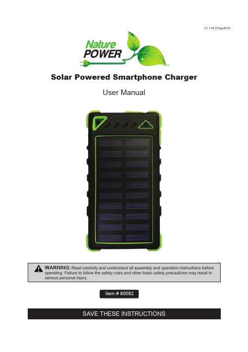
SAVE THESE INSTRUCTIONS Solar Powered Smartphone Charger User ManualItem # 80082V1.1-M 27Sep2019WARNING:Read carefully and understand all assembly and operation instructions before operating. Failure to follow the safety rules and other basic safety precautions may result in serious personal injury.Important Safety InformationThank you for choosing a Nature Power Product.Save the receipt and these instructions. It is important that you read the entire manual to become familiar with this product before you begin using it.This product is designed for certain applications only. the distributor cannot be responsible for issues arising from modification. We strongly recommend this product not be modified and/or used for any application other than that for which it was designed. If you have any question relative to a particular application, Do not use the product until you have first contacted the distributor to determine if it can or should be performed on the product.For technical question please call 1800-588-0590This solar charger is uniquely constructed with integrated Li-polymer 8000mAh battery.It has features of Waterproof, Dustproof, Shockproof .Dual USB output,LED lights.Page 2 of 4Never attempt to open or disassemble the solar charger.Never subject the solar charger to knock or blow.Do not let children play with the solar charger.The solar charger is waterproof but only for rains. Never be immersed in water or any other liquid.Do not leave the solar charger in airtight space when sunshine charging such as in car,may cause the maximum operating temperature(65℃)being exceeded.Do not throw the solar charger into the fire.Parts List1, Charging the solar charger via the solar panel.Place the solar charger under sunlight. the green LED indicator will keep on when the solar charger is charging by sunlight. When the solar charger is fully charged, LED indicators will be off.NOTE: Solar charging is only emergency charging method,please avoid prolonged exposure under the burning sun.2, Charging the solar charger from an external power source.Connect the solar charger's cable to a computer or laptop USB port, USB car charger or USB AC charger. blue led indicators are flashing to indicate that the solar charger is being charged. when the solar charger is fully charged. led indicators will be off.An external power source takes 5-8 hours to fully charge the solar charger.Page 3 of 43, Charging device.after 20 seconds.4, LEDKeep pressing the button for 2 seconds to turn on the 20LED light.Keep pressing the button for 2 times to turn on the single LED flashlight. 2 more times to turn off.When the 20LEDs on, single press the button to reduce luminance;Under low-light mode, single press the button to turn into SOS signal mode;Under SOS signal mode, single press the button to turn back to high light mode;Under high-light mode, pressing the button for 2 seconds to turn off the 20LED light.5, Power indication:Press the button to check the remain battery capacityLED Light(●ON ○OFF) Capacity○○○○ 0%●○○○ 0%-25%●●○○ 25%-50%●●●○ 50%-75%●●●● 75%-100%NOTE:1, When the solar charger is in use and the remained capacity in solar charger is less than 2%, the solar charger will automatically shut off in order to avoid over-discharge of the battery. When the solar charger begins to recharge, it takes 3 minutes before it can output any charging current.2, Because of the special Settings of Apple Corp, please use the apple original data cables when charging for Apple products.3, The Waterproof design can effectively avoid the accident in the process of use, but should avoid power bank in the water or other dangerous environments.Limited WarrantyNature Power warrants our products to the original purchaser that this product is free from d efects in materials and workmanship for the period of 1 year from date of purchase, In the case of pro duct defect, contact Nature Power customer service to receive trouble shooting. If defective part or unit s hould be returned, a Return Authorization Number must be issued by Nature Power and the defective part or unit should be returned to the authorized location at the purchasers’ expense. A dated proof of p urchase is required to receive warranty service. Once received at authorized location and defect prove s to be the result of defective material and workmanship, the defective part or unit will be replaced at w arrantors’ option and returned to the original purchaser at warrantors’ expense. No refunds will be gran ted by the warrantor, in the event of buyer’s remorse please contact your point of purchase within and in adherence to their return policy. Refunds are granted at the retailers’ discretions.Please contact Nature Power Products to acquire more information:1-800-588-0590****************************Made in ChinaPage 4 of 4。
太阳能充电器操作手册说明书
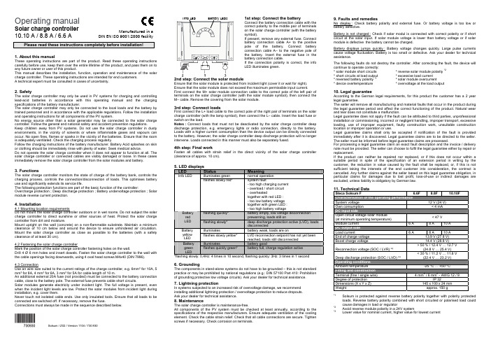
Operating manualSolar charge controller10.10 A / 8.8 A / 6.6 APlease read these instructions completely before installation!1. About this manualThese operating instructions are part of the product. Read these operating instructions carefully before use, keep them over the entire lifetime of the product, and pass them on to any future owner or user of this product.This manual describes the installation, function, operation and maintenance of the solar charge controller. These operating instructions are intended for end customers.A technical expert must be consulted in cases of uncertainty.2. SafetyThe solar charge controller may only be used in PV systems for charging and controlling lead-acid batteries in accordance with this operating manual and the charging specifications of the battery manufacturer.The solar charge controller may only be connected to the local loads and the battery by trained personnel and in accordance with the applicable regulations. Follow the installation and operating instructions for all components of the PV system.No energy source other than a solar generator may be connected to the solar charge controller. Follow the general and national safety and accident prevention regulations.Keep children away from PV systems. Do not use the solar charge controller in dusty environments, in the vicinity of solvents or where inflammable gases and vapours can occur. No open fires, flames or sparks in the vicinity of the batteries. Ensure that the room is adequately ventilated. Check the charging process regularly.Follow the charging instructions of the battery manufacturer. Battery Acid splashes on skin or clothing should be immediately rinse with plenty of water. Seek medical advice.Do not operate the solar charge controller when it does not appear to function at all. The solar charge controller or connected cables are visibly damaged or loose. In these cases immediately remove the solar charge controller from the solar modules and battery.3. FunctionsThe solar charge controller monitors the state of charge of the battery bank, controls the charging process, controls the connection/disconnection of loads. This optimises battery use and significantly extends its service life.The following protection functions are part of the basic function of the controller: Overcharge protection ; Deep discharge protection ; Battery undervoltage protection ; Solar module reverse current protection.4. Installation4.1 Mounting location requirementsDo not mount the solar charge controller outdoors or in wet rooms. Do not subject the solar charge controller to direct sunshine or other sources of heat. Protect the solar charge controller from dirt and moisture.Mount upright on the wall (concrete) on a non-flammable substrate. Maintain a minimum clearance of 10 cm below and around the device to ensure unhindered air circulation. Mount the solar charge controller as close as possible to the batteries (with a safety clearance of at least 30 cm).4.2 Fastening the solar charge controllerMark the position of the solar charge controller fastening holes on the wall.Drill 4 Ø 6 mm holes and insert dowels. Fasten the solar charge controller to the wall with the cable openings facing downwards, using 4 oval head screws M4x40 (DIN 7996).4.3 ConnectionUse an wire size suited to the current ratings of the charge controller, e.g. 6mm² for 10A, 5 mm² for 8A, 4 mm² for 6A, 3 mm² for 5A for cable length of 10 m.An additional external 20A fuse (not provided) must be connected to the battery connection cable, close to the battery pole. The external fuse prevents cable short circuits.Solar modules generate electricity under incident light. The full voltage is present, even when the incident light levels are low. Protect the solar modules from incident light during installation, e.g. cover them.Never touch not isolated cable ends. Use only insulated tools. Ensure that all loads to be connected are switched off. If necessary, remove the fuse.Connections must always be made in the sequence described below.1st step: Connect the batteryConnect the battery connection cable with thecorrect polarity to the middle pair of terminalson the solar charge controller (with the batterysymbol).If present, remove any external fuse. Connectbattery connection cable A+ to the positivepole of the battery. Connect batteryconnection cable A– to the negative pole ofthe battery. Insert the external fuse in thebattery connection cable.If the connection polarity is correct, the infoLED illuminates green.2nd step: Connect the solar moduleEnsure that the solar module is protected from incident light (cover it or wait for night).Ensure that the solar module does not exceed the maximum permissible input current.First connect the M+ solar module connection cable to the correct pole of the left pair ofterminals on the solar charge controller (with the solar module symbol), then connect theM– cable. Remove the covering from the solar module.3rd step: Connect loadsFirst connect the L+ load cable to the correct pole of the right pair of terminals on the solarcharge controller (with the lamp symbol), then connect the L– cable. Insert the load fuse orswitch on the load.Notes : Connect loads that must not be deactivated by the solar charge controller deepdischarge protection, e.g. emergency lights or radio connection, directly to the battery.Loads with a higher current consumption than the device output can be directly connectedto the battery. However, the solar charge controller deep discharge protection will no longerintervene. Loads connected in this manner must also be separately fused.4th step: Final workFasten all cables with strain relief in the direct vicinity of the solar charge controller(clearance of approx. 10 cm).5. LED displaysLED Status Meaningilluminates green normal operationInfo LEDflashes slowly red* system fault- too high charging current- overload / short circuit- overheatedtogether with red LED :- too low battery voltagetogether with green LED :- too high battery voltageflashing quickly* battery empty, low voltage disconnectionprewarning, loads still onBatteryredLED flashing slowly* deep discharge protection active (LVD), loadsdisconnectedilluminates battery weak, loads are onBatteryyellowLEDflashes slowly yellow* LVD reconnection setpoint has not yet beenreached, loads still disconnectedilluminates battery goodBatterygreenLEDflashes quickly green* battery full, charge regulation active*flashing slowly: 0,4Hz: 4 times in 10 second, flashing quickly: 3Hz: 3 times in 1 second6. GroundingThe components in stand-alone systems do not have to be grounded – this is not standardpractice or may be prohibited by national regulations (e.g.: DIN 57100 Part 410: Prohibitionof grounding protective low voltage circuits). Ask your dealer for technical assistance.7. Lightning protectionIn systems subjected to an increased risk of overvoltage damage, we recommendinstalling additional lightning protection / overvoltage protection to reduce dropouts.Ask your dealer for technical assistance.8. MaintenanceThe solar charge controller is maintenance-free.All components of the PV system must be checked at least annually, according to thespecifications of the respective manufacturers. Ensure adequate ventilation of the coolingelement. Check the cable strain relief. Check that all cable connections are secure. Tightenscrews if necessary. Check corrosion on terminals.9. Faults and remediesNo display : Check battery polarity and external fuse. Or battery voltage is too low orbattery defective.Battery is not charged : Check if solar modul is connected with correct polarity or if shortcircuit at the solar input. If solar module voltage is lower than battery voltage or if solarmodule is defective the battery cannot be charged.Battery displays jumps quickly : Battery voltage changes quickly. Large pulse currentscause voltage fluctuation. Battery is too small or defective. Ask your dealer for technicalassistance.The following faults do not destroy the controller. After correcting the fault, the device willcontinue to operate correctly:* solar module short circuits * reverse solar module polarity *2* short circuits at load output * excessive load current* reversed battery polarity *1* solar module overcurrent* device overtemperature * overvoltage at the load output10. Legal guaranteeAccording to the German legal requirements, for this product the customer has a 2 yearlegal guarantee.The seller will remove all manufacturing and material faults that occur in the product duringthe legal guarantee period and affect the correct functioning of the product. Natural wearand tear does not constitute a malfunction.Legal guarantee does not apply if the fault can be attributed to third parties, unprofessionalinstallation or commissioning, incorrect or negligent handling, improper transport, excessiveloading, use of improper equipment, faulty construction work, unsuitable constructionlocation or improper operation or use.Legal guarantee claims shall only be accepted if notification of the fault is providedimmediately after it is discovered. Legal guarantee claims are to be directed to the seller.The seller must be informed before legal guarantee claims are processed.For processing a legal guarantee claim an exact fault description and the invoice / deliverynote must be provided. The seller can choose to fulfil the legal guarantee either by repair orreplacement.If the product can neither be repaired nor replaced, or if this does not occur within asuitable period in spite of the specification of an extension period in writing by thecustomer, the reduction in value caused by the fault shall be replaced, or, if this is notsufficient taking the interests of the end customer into consideration, the contract iscancelled. Any further claims against the seller based on this legal guarantee obligation, inparticular claims for damages due to lost profit, loss-of-use or indirect damages areexcluded, unless liability is obligatory by German law.11. Technical DataSteca Solsum F 6.6F 8.8F 10.10FSystem voltage 12 V (24 V)Own consumption < 4 mADC input sideOpen circuit voltage solar module(at minimum operating temperature)< 47 VModule current 6 A 8 A 10 ADC output sideLoad current 6 A 8 A 10 AEnd of charge voltage 13.9 V (27.8 V)Boost charge voltage 14.4 V (28.8 V)Reconnection voltage (SOC / LVR) *³> 50 % / 12.4 V … 12.7 V(24.8 V … 25.4 V)Deep discharge protection (SOC / LVD) *³< 30 % / 11.2 V … 11.6 V(22.4 V … 23.2 V)Operating conditionsAmbient temperature -25 °C … +50 °CFitting and constructionTerminal (fine / single wire) 4 mm2 / 6 mm2 - AWG 12 / 9Degree of protection IP 32Dimensions (X x Y x Z) 145 x 100 x 24 mmWeight approx. 150 g*1Solsum is protected against reverse battery polarity together with polarity protectedloads. Reverse battery polarity combined with short circuited or polarised load couldcause damages in load or regulator*2Avoid reverse module polarity in a 24V system*3Lower value for nominal current, higher value for lowest currentInfo LED Battery LEDsManufactured in aDIN EN ISO 9001:2000 facilitySolsum / Z02 / Version 1104/ 730.930。
- 1、下载文档前请自行甄别文档内容的完整性,平台不提供额外的编辑、内容补充、找答案等附加服务。
- 2、"仅部分预览"的文档,不可在线预览部分如存在完整性等问题,可反馈申请退款(可完整预览的文档不适用该条件!)。
- 3、如文档侵犯您的权益,请联系客服反馈,我们会尽快为您处理(人工客服工作时间:9:00-18:30)。
太阳能无线充电器设计者:程鲁,崔佳林,曹灿,王旸指导教师:施悦(哈尔滨工程大学动力与能源工程学院,黑龙江哈尔滨,150001)作品内容简介进入21世纪以来,节能、环保成为了全世界各国对于可持续发展战略把握的重点,近年来我国也在大力倡导低碳节能的生活方式。
随着现代电力革命的不断深入,关于新的电能利用方式的发展方向已成为各国关注的焦点。
传统电能传输和使用方式限制了电能技术的发展,繁杂的电线不仅占据大量空间,也为人们的生活带来了很大的烦扰与不便,同时还存在一定安全隐患。
据统计,我国每年因电线老化、电线杂乱引发的事故所造成的经济损失高达20亿元,人员伤亡及潜在威胁更是无法预计。
为了解决以上问题,我们设计了一种基于电磁谐振的太阳能无线充电器。
装置基本思路:太阳能电池板蓄电池振荡信号发生模块宽频带高频功率放大模块谐振的发射线圈谐振接受线圈高频整流滤波电路负载。
太阳能电池板将太阳能转化为电能,并储存在蓄电池中,蓄电池再将电能供给振荡信号发生模块,振荡信号发生模块发出3.1MH左右高频频率信号,经过功放模块后输出10W功率给发射线圈,发射线圈和接收线圈具有相同的固有频率,当发射线圈所发射的频率达到固有频率时,即皆为3.1MHz左右的频率时,接、发射线圈间实现电磁谐振,能量就从发射极线圈以隧道方式传输至接受级线圈,从而实现了电能的无线传输,然后经过高频整流滤波电路将高频交流变成直流,供给手机等小功率电子设备。
创新点:(1)采用太阳能作为装置的能量来源,环保节能;(2)采用谐磁共振的方式实现无线电能传输,比一般的电磁感应式无线电能传输方式效率更高,传输距离更远;实验显示,在发射接收线圈匹配的情况下,晴天情况下,将太阳能电池板正对南方,与地面成30-40度夹角,BSM100-36型平板多晶硅太阳能电池板额定输出电压18V、功率5W,可在14h左右将12V-4AH松下免维护蓄电池电量充满。
在5-24V范围内调节第二路DC直流转换器输出电压,发现三星I9300手机可以在30mm-40mm距离内,与线圈轴线成300度范围内正常充电。
当手机充电基座距离发射基座近时,输出电压大;距离远时输出电压小,多余能量以驻波形式通过谐振电路返回功放,自动调节输出电流大小。
与手机连接的线圈具有稳压电路,可稳定输出4.2V-5V电压。
保证手机充电过程的稳定性。
装置不受非铁磁类介质影响,且对人体无伤害。
基于谐振耦合的无线供电装置,能解除电线对人类生活的约束,减少因电线老化引起的事故的发生,提高用电的安全性;在提倡环保的今天,本项目的研究成果积极的响应了保护环境和节能降耗号召,具有很强的推广性。
目录1.研究背景 (3)2.方案设计 (4)2.1设计方案的确定 (4)2.2 太阳电池板和蓄电池的选择 (8)2.3振荡信号发生模块的设计制作 (9)2.3.1 MAX038芯片介绍 (9)2.3.2 MAX038做成的正弦波信号输出电路图 (10)2.3.3 MAX038的波形输出控制 (11)2.4 功率放大模块的设计制作[11] (11)2.5 谐振匹配的初、次级线圈的设计制作 (12)2.6高频整流滤波电路........................................................................................................... .133.实验部分 (15)3.1调谐 (15)3.2实验结果及其分析 (17)3.2.1 传输效率 (17)3.2.2 线圈的品质因数 (22)4.经济分析 (23)4.1经济效益分析 (23)4.2 环保效益分析 (24)4.3实验运行成本分析 (25)5.创新点及优点 (25)5.1创新点 (25)5.2优点 (26)5.3应用前景 (26)参考文献 (27)1 研制背景及意义无线电技术用于通信, 已经在全世界流行了近一百年。
从当初的无线电广播和无线电报, 发展到现在的卫星和微波通信,以及普及到全球几乎每一个人的移动通信、无线网络、GPS等。
无线通信极大地改变了人们的生产和生活方式,没有无线通信, 信息化社会的目标是不可议的。
然而,无线通信传送的都是微弱的信息而不是功率较大的能量。
因此许多使用极为方便的便携式的移动产品, 都要不定期地连接电网进行充电,也因此不得不留下各种插口和连接电缆。
传统的电气设备都是通过插头或插座等电连接器的接触进行供电,这就很难实现具有防水性能的密封工艺,并且存在较大安全隐患,而且这种个性化的线缆使得不同产品的充电器很难通用。
如果彻底去掉这些尾巴,移动终端设备就可以获得真正的自由。
也易于实现密封和防水。
这个目标必须要求能量也像信息一样实现无线传输。
国际无线充电联盟(Wireless Power Consortium,WPC )Qi无线充电国际标准规定:Qi无线充电系统需由基站和移动设备组成。
基站包含一个或多个发射器,发射器将提供用以接收的能量。
移动设备包含一个接收器用来提供电能给负载(如手机),接收器还将为发射器提供信息。
发射器内有能量转换单元,将电能转换为无线能源信号,接收器内的能量收集单元则将无线能源信号转换为电能。
接收器将根据需要将电能输送至负载,发射器根据接收器的需要适配能量传递。
诺基亚、飞利浦、LG、三星、索尼爱立信以及RIM等众多国际知名手机厂商都很支持这一技术,按照Qi标准要求,相继推出支持Qi标准的无线充电器产品,并首先为苹果iPhone3GS和黑莓Blackberry Curve 8900用户带来无线充电的全新体验。
同时市场调研数据显示,无线充电设备市场在2013年将达到140亿美元的规模。
飞利浦已经开始生产含有无线充电设置新型手机了,该机将标配无线充电器Xenium Q1(Qi无线充电联盟标准)。
Qi基于电磁感应原理进行输电。
感应耦合电能传输系统的由发射器线圈和接收器线圈组成,两个线圈共同构成一个电磁耦合感应器。
发射器线圈所携带的交流电生成磁场,并通过感应使接收器线圈产生电压。
现有的无线充电器局限:一,利用电磁感应技术,有较大的漏磁,耦合系数较小,会增大输入电流与电压之间的相位差,限制了能量传输的效率,不适合大功率,远距离传输,只能在3—30mm之间进行小功率充电。
同时,线圈相互耦合干扰会带来能量损耗;二,充电基座带有电源线,这就要求充电基座附近有电源插座,限制了充电器范围。
从某种意义上将,现有无线充电器,只是没有将USB接口直接接在手机上,但手机需要紧贴基座放置,而基座带有电源线,也就是说将手机的电源线转移给了充电基座,这给无线充电技术带来极大的不便和限制。
基于以上背景条件考虑,我们研发了本套无线充电装置,该装置是基于电磁谐振的太阳能无线充电器。
该无线充电器可以为手机等小功率电子设备实现中远距离无线充电。
其由发射模块和接收模块组成,手机等小功率电子设备接在接收模块上,接收来自发射模块传输过来的能量。
本项目的研究内容:发挥太阳电池板优势,利用太阳能电池板将太阳能转化为发电能储存在蓄电池内,然后由蓄电池供给给高频功放和信号发生器,传输给发射极线圈,通过谐磁共振将能量传输给中远距离的接收线圈,经整流滤波电路,将交流转成直流,供给手机充电。
本研究主要内容包括:(1)对设计方案和设备的选择做出了一个整体性的概括和研究,其中包括:无线供电方式的的选择,太阳能电池板选择、信号震荡发生器、宽频带高频功放、接发射线圈、高频整流滤波电路、高频分离式变压器的制作。
(2)探究频率对线圈的影响,考虑高频情况下导线的集肤效应。
(3)线圈线径、直径、材料、外物对无线供电装置效率的影响。
(4)研究Q值对整个系统的影响。
(5)进行工式化推理;进行经济性分析。
验证该项目可行性、科学性。
该充电器是针对目前国内外无线充电设备的要求,并参考了目前国内外许多无线充电技术,其避免了现有感应式无线充电器的局限,提高了无线充电器的范围,并利用太阳能发电技术,既实现了装置的便携又充分体现节能环保的理念。
在提倡环保的今天,本项目的研究成果积极的响应了保护环境和节能降耗号召,具有很强的推广性。
2.方案设计2.1设计方案的确定无线能量传输通常是指电能的无导线传输,即不借助实物连接线,实现电能的无线传输。
传统电能的传输主要是利用金属导线直接接触来进行的,这给我们带来了许多的不便。
而无线电能传输就不同了,电能从发射端待接收端无接触,提高了用电设备获得电能的灵活性。
无接触电能传输技术对移动电气设备、工作于水下及易燃易爆等特殊环境下的电气设备提供可靠的电能供应。
目前常用的无线供电方法有三种,即电磁感应式、电磁谐振式和电磁辐射式[1-7]:1.电磁感应式一般的电磁感应可分为两类: 静电感应和动电感应,目前后者使用较多静电感应方案利用容性耦合传输能量系统通过高频高压的交变电流产生的电场,在两个或多个相互隔离的端点之间传递能量电机工程领域的先驱,尼古拉.特斯拉曾对静电感应方式做过实验,成功利用无线方式让灯泡发光但要实现高频高压的交变电流存在有一定难度,因此,一般民用场合很难使用动电感应方案利用感性耦合传输能量,在一次侧线圈中通上交流电,产生交变的电场,利用近场范围内线圈之间的互感实现能量的传输,这与变压器内部的原理非常相似该方案应用比较广泛,如变压器内部的原理电动牙刷的充电电磁炉加热等,主要缺点是传输效率会随着传输的距离增加而迅速衰减2.电磁辐射式电磁波辐射方案,即在供电端将电能转化为电磁波的形式并向空间发射,在接收端收集并恢复成直流或交流电的形式该。
方案在空间发电领域有一定的应用,太阳能卫星将能量收集后转化为微波形式,通过天线向地球发射; 在地面端,通过微波整流天线将能量接收并转化当电磁波的波段为可见光时,该方案又会衍生出另外一种形式,即电能的激光传输这样,虽然提高了方向性和传输效率,但由于可见光的特性,传输中需要保持光路畅通,无遮挡电磁辐射方案的原理较为成熟,但在大功率的情况下对天线的设计要求较高。
如果是可见光,还会存在遮挡问题另外,由于存在电磁辐射,故在民用领域的应用场合传输的功率会受到限制,还可能与通信系统频率互相干扰电磁辐射传输方式,容易对通信造成干扰、能量散射损耗大,定向性差,传输效率低。
3.电磁谐振式电磁谐振型电能传输技术主要是利用接收天线固有频率与发射场电磁频率相一致时引起电磁共振,发生强电磁耦合的工作原理来实现电能的高效传输。
2007年,麻省理工学院Soljacic助理教授带领的研究小组成功地将一盏距离发射器2.13m外的60W灯泡点亮。
实验表明:当收发双方相隔2m时,传输60W功率的辐射损失仅为5W。
因此,在几米内的中程距离传输电能是可行的。
采用ERPT技术,电能传输距离可以达3-4m,传输功率可高达几kW。