TVR14241中文资料
TVR-V压敏电阻中文资料
用途
1. 2. 3. 4. 5. 6. 7. 8. 电源供应器 家用电器 工业设备 通信设备 智能控制型电表 电力线智能通讯设备 照明 光伏系统
备注:产品型号后面打印一码 V 代表为 TVR-V 系列
编码规则
T 1 V 2 R 3 1 4 4 5 2 6 4 7 1 8 K 9 S 10 11 12 13 14 15
产品尺寸
35 39 42 49 53 58 65 70 80 85 92 92 95 98 100 110 130 140 155
适用于 SPD Type 3 应用
42
2013.03
产品规格与数据若有变更,恕不另行通知
氧化锌压敏电阻器:TVR-V 系列
浪涌保护用插件型 (中能系列)
(V) 340 360 395 455 500 550 595 650 710 775 845 930 1020 1120 1235 1355 1500 1650 1815
VDC
(V) 170 180 200 225 250 275 300 320 350 385 410 450 510 560 615 670 745 825 895
Cp
(pF) 970 880 820 720 650 600 550 500 440 400 370 340 300 290 270 250 220 200 180
UL rd 1449 3 SPD 应用类型*2
TVR14102-V 1000 (900~1100) TVR14112-V
1100 (990~1210)
备注:包装及内部控制代码未使用时, 第 11 码为可选后辍。
40
2013.03
产品规格与数据若有变更,恕不另行通知
4 1 RGB 遥控器说明书
The controller keeps the LED Length that is set stored in its memory, and will operate under that setting. o For example: If you have two connected LED light strips that each have 30 LED lights with the LED length set to that length, when you remove a strip and still wish to shorten the LED length, you must press the LGTH- button 10 times (each press decreases the length by 3 lights x 10 presses = 30) to account for the missing strip before you will notice a change.
Install as instructed. o Read all instructions carefully before installation and do not discard instructions. o Careful installation will ensure prolonged life. Repeated installations may shorten the life of this product.
TV04A330J中文资料
TV04A330J中文资料Working Peak Reverse Voltage: 5.0 - 170 Volts Power Dissipation: 400 WattsTV04A5V0 Thru TV04A171FeaturesIdeal for surface mount applications Easy pick and placePlastic package has Underwriters Lab. flammability classification 94V-0 Typical IR less than 1uA above 10V Fast reponse time: typically less 1nS for uni-direction, less than 5nS for bi-directiona, from 0 V to BV min.Mechanical dataCase: JEDEC DO-214AC molded plastic Terminals: solderable per MIL-STD-750,method 2026Polarity: Cathode band denoted Mounting position: AnyApprox. weight:0.064 gram Maximum Ratings and Electrical CharactericsRating at 25 C ambient temperature unless otherwise specified.Single phase, half wave, 60Hz, resistive or inductive load.For capacitive load, derate current by 20%Characteristics Peak Power Dissipation on 10/1000uS Waveform (Note 1, Fig. 1)Peak Pulse Current of on 10/1000uS Waveform (Note 1, Fig.3)Steady State Power Dissipation at T L =75 C (Note 2)Peak Forfard Surge Current, 8.3mS SingleHalf Sine-Wave Superimposed on RatedLoad, Uni-Directional Only (Note 3)Maxinum Instantaneous Forward Voltage at 25.0A for Uni-Directional only (Note 3 & 4) Operation Junction T emperature Range Storage Temperature RangeSymbolP PPMI PPM P M(AV)I FSM VF Tj T STGNote: 1. Non-Repetitive Current Pulse, per Fig. 3 and Derated above T A=25 C, per Fig. 2. 2. Mounted on 5.0x5.0mm Copper Pads to Each T erminal. 3. Lead T emperature at TL=75 C per Fig. 54. Measured on 8.3 mS Single Half Sine-Wave for Uni-Directional Devices Only.5. Peak Pulse Power Waveform is 10/1000uS.Value 400 See Table 1 1.040 3.5 -55 to +150 -55 to +150UnitsWatts A WattsAVolts C CRating and Characteristic Curves (TV04A5V0 Thru TV04A171) Fig. 1 - Reverse CharacteristicsFig. 2 - Pulse Derating Ciurve0.1 1.0 10 100 1000 10000Pulse Width, t d (uS)P e a k P u l s e P o w e r , P P P M (K W )0 25 50 75 100 125 150 175Ambient Temperature,T A ( C)P e a k p u l s e P o w e r (P p p ) o r C u r r e n t (I p p )D e r a t i n g i n P e r c e n t (%)Fig. 4 - Typica l Junction CapacitanceJ u n c t i o n C a p a c i t a n c e , C j (p F ) Breakdown Voltage,V BR (Volts)1.0 10 100 1,000Fig. 5 - Steady State Power Derating CurveLeadt Temperature,T L ( C)S t e a d y S t a t e P o w e r D i s s i p a t i o n , P M (A V ), W a t t sFig. 6 - Maxinum Non-Repetitive Peak Forward Surge Current (Uni- Directional Only)P e a k F o r w a r d S u r g e C u r r e n t , I F S M (A )100503010Number of Cycle at 60Hz1.41.2 1.0 0.8 0.6 0.4 0.2 0Fig. 3 - Pulse WaveformTime, t (mS)0 1.0 2.0 3.0 4.0P e a k P u l s e C u r r e n t , I P P M ( %)Table 1. Specification1) Suffix K Denotes 10% tolerance devices, suffix J denotes 5% tolerance devices.2) Suffix B after part number to specify bi-directional devices.3) For bi-directional devices having VR of 10 volts and under, the IR limit is double.。
2SK241中文资料(toshiba)中文数据手册「EasyDatasheet - 矽搜」
Crss
¾
3.0
¾
pF
¾ 0.035 0.050 pF
Gps
VDS = 10 V, V GS = 0,
NF
f = 100兆赫(图1)
¾
28
¾
dB
¾ 1.7 3.0 dB
O: 1.5~3.5, Y: 3.0~7.0, GR: 6.0~14.0
1
2003-03-27
芯片中文手册,看全文,戳
特点 漏源电压 栅源电压 漏极电流 漏极功耗 通道温度 存储温度范围
电气特性
特点 栅极漏电流 漏源电压 漏极电流 门源截止电压 远期转移导纳 输入电容 反向传输电容 功率增益 噪声系数
注:I DSS 分类
(Ta = 25°C)
符号
VDS VGS ID PD Tch Tstg
等级
单元
20
V
±5
V
30
mA
芯片中文手册,看全文,戳
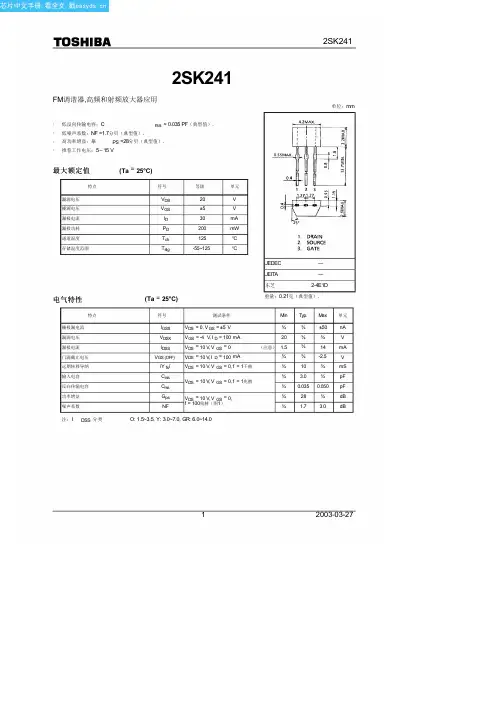
2SK241
2SK241
FM调谐器,高频和射频放大器应用
单位:mm
· 低反向传输电容:C
rss = 0.035 PF(典型值).
· 低噪声系数:NF =1.7分贝(典型值).
· 高功率增益:摹
PS =28分贝(典型值).
· 推荐工作电压:5〜15 V
最大额定值
200
mW
125
°C
-55~125
°C
(Ta = 25°C)
JEDEC
―
JEITA
―
东芝
2-4E1D
重量:0.21克(典型值).
符号
测试条件
Min Typ. Max 单元
IGSS
Crestron HD-RX-4K-410-C-E-SW4 4K 多格式 AV 切换接收器说明书
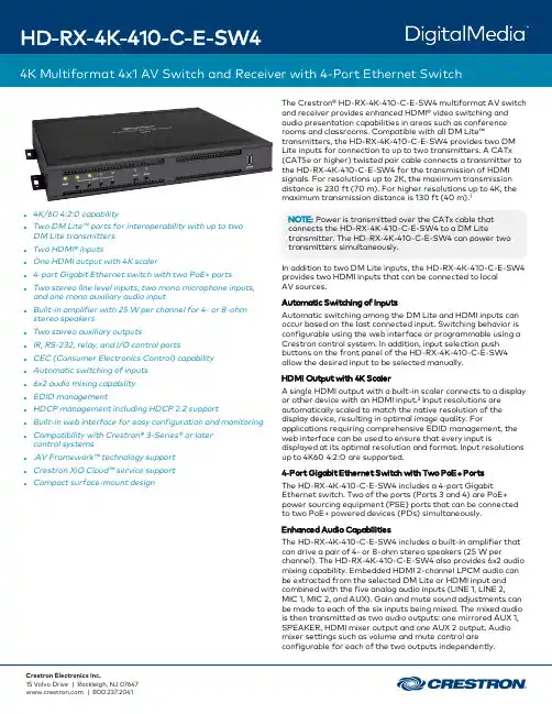
l4K/604:2:0capabilityl Two DM Lite™ports for interoperability with up to two DM Lite transmittersl Two HDMI®inputsl One HDMI output with4K scalerl4-port Gigabit Ethernet switch with two PoE+portsl Two stereo line level inputs,two mono microphone inputs, and one mono auxiliary audio inputl Built-in amplifier with25W per channel for4-or8-ohm stereo speakersl Two stereo auxiliary outputsl IR,RS-232,relay,and I/O control portsl CEC(Consumer Electronics Control)capabilityl Automatic switching of inputsl6x2audio mixing capabilityl EDID managementl HDCP management including HDCP2.2supportl Built-in web interface for easy configuration and monitoringl Compatibility with Crestron®3-Series®or later control systemsl.AV Framework™technology supportl Crestron XiO Cloud™service supportl Compact surface-mount design The Crestron®HD-RX-4K-410-C-E-SW4multiformat AV switch and receiver provides enhanced HDMI®video switching and audio presentation capabilities in areas such as conference rooms and patible with all DM Lite™transmitters,the HD-RX-4K-410-C-E-SW4provides two DM Lite inputs for connection to up to two transmitters.A CATx (CAT5e or higher)twisted pair cable connects a transmitter to the HD-RX-4K-410-C-E-SW4for the transmission of HDMI signals.For resolutions up to2K,the maximum transmission distance is230 ft(70 m).For higher resolutions up to4K,the maximum transmission distance is130 ft(40 m).1NOTE:Power is transmitted over the CATx cable that connects the HD-RX-4K-410-C-E-SW4to a DM Lite transmitter.The HD-RX-4K-410-C-E-SW4can power two transmitters simultaneously.In addition to two DM Lite inputs,the HD-RX-4K-410-C-E-SW4 provides two HDMI inputs that can be connected to localAV sources.Automatic Switching of InputsAutomatic switching among the DM Lite and HDMI inputs can occur based on the last connected input.Switching behavior is configurable using the web interface or programmable using a Crestron control system.In addition,input selection push buttons on the front panel of the HD-RX-4K-410-C-E-SW4 allow the desired input to be selected manually.HDMI Output with4K ScalerA single HDMI output with a built-in scaler connects to a display or other device with an HDMI input.2Input resolutions are automatically scaled to match the native resolution of the display device,resulting in optimal image quality.For applications requiring comprehensive EDID management,the web interface can be used to ensure that every input is displayed at its optimal resolution and format.Input resolutions up to4K604:2:0are supported.4-Port Gigabit Ethernet Switch with Two PoE+PortsThe HD-RX-4K-410-C-E-SW4includes a4-port Gigabit Ethernet switch.Two of the ports(Ports3and4)are PoE+ power sourcing equipment(PSE)ports that can be connected to two PoE+powered devices(PDs)simultaneously.Enhanced Audio CapabilitiesThe HD-RX-4K-410-C-E-SW4includes a built-in amplifier that can drive a pair of4-or8-ohm stereo speakers(25W per channel).The HD-RX-4K-410-C-E-SW4also provides6x2audio mixing capability.Embedded HDMI2-channel LPCM audio can be extracted from the selected DM Lite or HDMI input and combined with the five analog audio inputs(LINE1,LINE2,MIC 1,MIC 2,and AUX).Gain and mute sound adjustments can be made to each of the six inputs being mixed.The mixed audio is then transmitted as two audio outputs:one mirrored AUX1, SPEAKER,HDMI mixer output and one AUX2output.Audio mixer settings such as volume and mute control are configurable for each of the two outputs independently.Device ControlEquipped with onboard control ports,the HD-RX-4K-410-C-E-SW4can control various devices in a room.The COM(RS-232) port and CEC over the HDMI output can enable the display device to be turned on or off automatically without the use of a control system.With the use of a control system,the IR port can also control the display device.Two relay ports are provided for controlling a projection screen and other low-voltage contact-closure activated equipment.Two Versiport I/O ports enable the integration of devices such as power sensors and motion detectors.An Ethernet port connection to a LAN also provides control by enabling use of the built-in web interface as well as connection to a control system.NOTE:The IR,COM,and Ethernet ports cannot be used to extend signals over a DM Lite connection..AV Framework™Technology SupportIn addition to a built-in web interface and control system programming,the built-in.AV Framework technology of the MPC3-201and MPC3-302control systems can be used to control the HD-RX-4K-410-C-E-SW4as a switcher.(For information about.AV Framework technology,visit/avframework.)Crestron XiO Cloud™Service SupportThe HD-RX-4K-410-C-E-SW4is compatible with the Crestron XiO Cloud service,which is an IoT(Internet of Things)based platform for remotely provisioning,monitoring,and managing Crestron devices across an enterprise or an entire client base. The service enables installers and IT managers to deploy and manage thousands of devices in the amount of time it would ordinarily take to manage a single device.For more information, visit /xiocloud.Compact DesignCompact in design,the HD-RX-4K-410-C-E-SW4can be mounted onto a flat surface such as a wall or attached to the underside of a table.SpecificationsVideoSwitcher:4x1auto-switching or manual,audio-follows-video, Crestron Auto-Locking®and QuickSwitch HD™technologiesScaler(HDMI Output):4K video scaler with motion-adaptive deinterlacing,intelligent frame rate conversion,Deep Color support,content-adaptive noise reduction,3:2/2:2pull-down detection and recoveryInput Signal Types:HDMI with Deep Color and4K(DVI and Dual-Mode DisplayPort™interface compatible3)on Inputs1-2, DM Lite with Deep Color and4K on Inputs3-4Output Signal Types:HDMI with Deep Color and4K(DVI compatible4)Copy Protection:HDCP2.2Maximum Resolutions:Common resolutions are listed below for the HDMI and DM Lite inputs.NOTES:l Custom resolutions are supported at pixel clock rates up to300MHz.l Interlaced video sources are not supported.Scaler Output Resolutions,HDMI:Auto(EDID preferred),1280x720p@50Hz(720p50),1280x720p@60Hz(720p60),1920x1080i@25Hz(1080i25), 1920x1080i@30Hz(1080i30),1920x1080p@30Hz(1080p30),1920x1080p@25Hz(1080p25),1920x1080p@24Hz(1080p24),1920x1080p@50Hz(1080p50),1920x1080p@60Hz(1080p60),3840x2160p@24Hz,3840x2160p@25Hz,3840x2160p@30Hz, 4096x2160p@24Hz,4096x2160p@25Hz,4096x2160p@30Hz, 3840x2160p@50Hz,3840x2160p@60Hz,4096x2160p@50Hz, 4096x2160p@60HzAudio,GeneralSwitcher/Mixer:6x2audio mixer:Audio Inputs:Two stereo2-channel LINE inputsTwo mono1-channel MIC inputsOne mono1-channel AUX inputOne stereo2-channel LPCM audio extracted fromthe selected HDMI or DM Lite input sourceAudio Outputs:One mirrored AUX1,SPEAKER,and HDMI mixer output,stereo2-channelOne AUX2output,stereo2-channelAnalog-to-Digital Conversion:24-bit48kHzDigital-to-Analog Conversion:24-bit48kHzFrequency Response,Analog Audio Outputs:20Hz to20kHz±0.5dB(AUX outputs)20Hz to20kHz@full power±3dB(speaker output)S/N Ratio,Analog Audio Outputs:>95dB@10dBV,20Hz to20kHz,A-weighted(AUX outputs) >90dB@10dBV,20Hz to20kHz,A-weighted(speaker output)THD+N,Analog Audio Outputs:<0.005%@1kHz and10dBV(AUX outputs)<0.3%@1kHz and10dBV(speaker output)Stereo Separation,Analog Audio Outputs:20Hz to20kHz≤80dB(AUX outputs)20Hz to20kHz≤60dB(speaker output)Audio,Microphone InputsTwo balanced1-channel microphone inputs(MIC1and MIC2): Input Signal Type:Mono analogPhantom Power:+48VDC,12mA,enable or disable per channel Gain:0dB to+60dB per channel in1dB incrementsMute:Enable or disable per channelAudio,Line InputsTwo balanced/unbalanced2-channel line inputs(LINE1and LINE2):Input Signal Type:Stereo analogBalanced Line Input Level:4VrmsUnbalanced Line Input Level:2VrmsLine Input Impedance:>10k ohmsAudio,Auxiliary InputOne balanced1-channel auxiliary input(AUX):Input Signal Type:Mono analogBalanced Line Input Level:4VrmsLine Input Impedance:>10k ohmsAudio,Source InputsTwo HDMI and two DM Lite inputs(HDMI1-2and DM Lite3-4):Input Signal Types:HDMI(Dual-Mode DisplayPort interface compatible),DM LiteDigital Formats:2-channel LPCMAudio OutputsOne mirrored SPEAKER,HDMI,and balanced/unbalancedAUX1mixer output:Output Signal Type/Format:Stereo2-channel AUX1Output Impedance:200ohms balanced,100ohms unbalancedAUX1Maximum Output Level:4Vrms balanced,2Vrms unbalancedSelected Source:-80dB to+20dB level adjustment rangeplus MuteMIC1-2:-80dB to+20dB level adjustment range plus Mute LINE1-2:-80dB to+20dB level adjustment range plus Mute AUX:-80dB to+20dB level adjustment range plus Mute Master Volume:-80dB to+20dB level adjustment rangeplus MonoAmplifier Output Power:25W RMS per channel@8ohms,4ohms tolerantAmplifier Power:On or offMute:Enable or disable independently for AUX1,SPEAKER, and HDMI mixer outputOne balanced/unbalanced AUX2output:Output Signal Type/Format:Stereo2-channelOutput Impedance:200ohms balanced,100ohms unbalanced Maximum Output Level:4Vrms balanced,2Vrms unbalanced Selected Source:-80dB to+20dB level adjustment rangeplus MuteMIC1-2:-80dB to+20dB level adjustment range plus Mute LINE1-2:-80dB to+20dB level adjustment range plus Mute AUX:-80dB to+20dB level adjustment range plus Mute Master Volume:-80dB to+20dB level adjustment rangeplus MonoMute:Enable or disable for AUX2CommunicationsEthernet:100/1000Mbps,auto-switching,auto-negotiating, auto-discovery,full/half duplex,CIP,DHCP,web browser setup and controlRS-232:2-way device control and monitoring up to115.2k baud with hardware and software handshakingIR:1-way device control via infrared up to60kHzHDMI:HDCP2.2,EDID,CECDM Lite:HDCP2.2,EDIDConnectorsL/R,LINE INPUT1-2:(2)5-pin3.5mm detachable terminal blocksMIC INPUT1-2:(2)3-pin3.5mm detachable terminal blocks AUX INPUT:(1)3-pin3.5mm detachable terminal blockHDMI INPUT1-2:(2)HDMI Type A connectors,female;HDMI digital video/audio inputs;DVI and Dual-Mode DisplayPort interface compatible3DM Lite INPUT3-4:(2)8-pin RJ-45yellow connectors,female, shielded;DM Lite input ports for connection to DM Lite transmittersL/R,AUX OUT1-2:(2)5-pin3.5mm detachable terminal blocks HDMI OUTPUT:(1)HDMI Type A connector,female;HDMI digital video/audio output;2DVI compatible4NOTE:CEC over the HDMI output provides Power On/Off control of the display device without a control system or full programmable control of any device with a control system. Ethernet1-4:(4)8-pin RJ-45connector,female;100BASE-TX/1000BASE-T Ethernet ports;Ports3-4:PoE+Power Sourcing Equipment(PSE)outputs, IEEE802.3at Type2PoE+Class4(25.5W)compliant SPEAKER OUTPUT:(2)2-pin7.62mm reversed gender20A detachable terminal blocks,power amplifier outputs;Wire Size:Terminals accept up to12AWG(3.31mm);Output is direct-coupled—not transformer isolatedI/O1-2:(2)2-pin detachable terminal blocks;Comprise2Versiport digital input/output or analog input ports (referenced to GND);Digital Input:Rated to0-24VDC,input impedance20k ohms, logic threshold>3.125V low/0and<1.875V high/1;Digital Output:250mA sink from maximum24VDC,catch diodes for use with real world loads;Analog Input:Rated for0-10VDC,protected to24VDC maximum,input impedance21k ohms with pull-up resistor disabled;Programmable5V,2k ohms pull-up resistor per pinRLY1-2:(2)2-pin detachable terminal blocks;Comprise8normally open,isolated relays;Rated1A,30VAC/VDC;MOV arc suppression across contactsIR:(1)2-pin3.5mm detachable terminal block;IR output control port;supports IR up to60kHz;IRP2emitter sold separatelyNOTE:The IR port provides Power On/Off control of the display device with the use of a control system.COM:(1)5-pin3.5mm detachable terminal block;Bidirectional RS-232port;Supports RS-232up to115.2k baud with hardware and software handshakingNOTE:The COM port provides Power On/Off control of the display device without a control system or fullprogrammable control of any device with a control system.100-240V4A-2A50/60Hz:(1)IEC60320C14mains power inlet;Mates with removable power cord,includedNOTE:This power connection powers both the HD-RX-4K-410-C-E-SW4and all connected DM Lite transmitters.When connected to the HD-RX-4K-410-C-E-SW4,DM Lite transmitters must not be connected to power.SERVICE:(1)USB Type A connector,female;For factory use onlyControls and IndicatorsPWR:(1)LED,indicates that power is being applied to theHD-RX-4K-410-C-E-SW4.Amber indicates that the device is booting.Green indicates that the device is operational.INPUT1-4:(4)Push buttons for manual input selection and (4)LEDs.Green indicates that video is switched.Amber indicates that video is detected but is not switched.AUTO:(1)Push button to enable or disable automatic switching,and(1)green LED to indicate that automatic switching is enabledSETUP:(1)Red LED and(1)push button for display of IP address on the HDMI outputDM Lite:(2)LEDs on RJ-45connector.Green indicates that a DM Lite link is established.Flashing amber indicates non-HDCP video and solid amber indicates HDCP video.Ethernet:(2)LEDs on RJ-45connector.Green indicates that an Ethernet link is established.Flashing amber indicates Ethernet activity.PowerMains Power:4A-2A@100-240VAC,50/60HzNOTE:The AC mains power connection powers both theHD-RX-4K-410-C-E-SW4and all connected DM Lite transmitters.When connected to the HD-RX-4K-410-C-E-SW4,DM Lite transmitters must not be connected to power.EnvironmentalTemperature:32°to104°F(0°to40°C)Humidity:10%to90%RH(non-condensing)EnclosureChassis:Metal,black finish,vented sides,2mounting flanges attachedMounting:Surface mountDimensionsHeight:10.22in.(260mm)Width:14.18in.(361mm)with mounting flanges attached Depth:1.74in.(45mm)ComplianceUL®Listed for US and Canada,CE,IC,FCC Part15Class B digital deviceModel and AccessoriesModelHD-RX-4K-410-C-E-SW4:4K Multiformat4x1AV Switch and Receiver with4-Port Ethernet SwitchAvailable AccessoriesFor supported accessories,visit the HD-RX-4K-410-C-E-SW4 product page at .Notes:1.For DM Lite connections,use Crestron DM-CBL-8G,CrestronDM-CBL-ULTRA,or third-party CAT5e or higher cable.To safeguardagainst unpredictable environmental electrical noise that may impactperformance at resolutions above1080p,shielded cable and connectors are recommended for all applications and are required when bundlingmultiple cables in a wire run.Wire and cables sold separately.DM Lite ports are not compatible with DigitalMedia8G+®,HDBaseT®,PoE,or PoDMtechnology or any other type of CATx based interface or network.2.For information about compatibility of the HDMI output with CrestronHDMI extenders,refer to Online Help Answer ID1000503on the Crestron website().3.The HDMI input requires an appropriate adapter or interface cable toaccommodate a DVI or Dual-Mode DisplayPort signal.CBL-HDI-DVIinterface cables are available separately.4.The HDMI output requires an appropriate adapter or interface cable toaccommodate a DVI signal.CBL-HDI-DVI interface cables are availableseparately.This product may be purchased from an authorized Crestron dealer.To find a dealer,please contact the Crestron sales representative for your area.A list of sales representatives is available online at/How-To-Buy/Find-a-Representative or by calling855-263-8754.The specific patents that cover Crestron products are listed online at/legal/patents.Certain Crestron products contain open source software.For specific information,visit /opensource.Crestron,the Crestron logo,.AV Framework,3-Series,Auto-Locking,Crestron XiO Cloud,DigitalMedia,DigitalMedia8G+,DM Lite,and QuickSwitch HD are either trademarks or registered trademarks of Crestron Electronics,Inc.in the United States and/or other countries.DisplayPort is either a trademark or registered trademark of Video Standards Association in the United Statesand/or other countries.HDBaseT is either a trademark or registered trademark of the HDBaseT Alliance in the United States and/or other countries.HDMI and the HDMI logo are either trademarks or registered trademarks of HDMI Licensing LLC in the United States and/or other countries.UL is either a trademark or registered trademark of Underwriters Laboratories,Inc.in the United States and/or other countries.Other trademarks,registered trademarks,and trade names may be used in this document to refer to either the entities claiming the marks and names or their products.Crestron disclaims any proprietary interest in the marks and names of others.Crestron is not responsible for errors in typography or photography.Specifications are subject to change without notice.©2019Crestron Electronics,Inc.Rev11/22/19。
TVR14471中文资料
18
17
22
20
26
25
31
30
38
35
45
40
56
50
65
60
85
75
100
95
125
115 150
130 170
140 180
150 200
175 225
195 250
215 275
230 300
250 320
275 350
300 385
Max. Clamping Voltage
Max. Energy
Reference Capacitance
Dimensions
@1KHZ (pf) 3800 3600 3400 2900 1620 1550 1500 1200 900 750 620 500 400 360 310 290 260 230 210 190 180 160 150 140 130 120 110 100 90
Reference Capacitance
Dimensions
@1KHZ (pf) 1600 1500 1450 1400 1100 850 600 580 460 400 350 300 150 140 130 120 110 100 105 90 85 80 75
T(max.) (mm) 3.9 4.1 4.3 4.5 4.0 4.1 4.3 4.6 4.0 4.2 4.4 4.7 4.2 4.3 4.4 4.5 4.7 4.6 4.7 4.8 5.0 5.2 5.3
1200
600
1200
600
1200
600
1200
600
1200
压敏电阻
3
TVR10751-D TVR10751KSW 750 (675~825) 465 615 25 1235 4000
0.4
134
170 4.9 6.8 3.7
3
TVR10821-D TVR10821KSW 820 (738~902) 510 670 25 1355 4000
0.4
146
140 4.9 6.8 3.4
(仅 TVR20 适用)
备注:1. 包装及内部控制代码未使用时﹐第 11 码为可选后辍。 2. 若料号打印以”+”取代”*”,请洽销售人员。
兴勤电子工业股份有限公司
产品规格与数据若有变更,恕不另行通知
1
2011.01
氧化锌压敏电阻器:TVR-D 系列
浪涌保护用插件型(高能系列)
氧化锌压敏电阻器:TVR-D 系列
浪涌保护用插件型(高能系列)
特点
1. 本体尺寸 Ф7~ Ф 20mm 2. 宽工作电压范围:115Vac ~ 680Vac 3. 最大通流等级可达13KA 4. 最大能量等级可达720焦耳 5. 安规认证:UL 1449 3rd /cUL/VDE/CQC 6. TVR10-D、14-D、20-D符合IEC 60950-1 Annex Q需求 7. TVR20-D系列适用SPD Type 2应用 8. 提供符合RoHS与无卤规范系列产品
A
MAX 300
C d
d 0.6±0.02 0.8±0.02 0.8±0.02 1.0±0.02
P. 5±1 7.5±1 7.5±1 10±1
A max. 12.5 18.0 22.0 29.0
(单位: mm) T max. W
请见电气特性表
兴勤电子工业股份有限公司
TVR中文手册
步驟一、D/A1. D/A2 輸出電壓調整:........................................................36 步驟二、AD/DA 之輸入電壓調整.............................................................37 IF 校正 .................................................................................................................38 IF 電流源校正共分為四個步驟 : ..............................................................38 比對 IF 板 OP 放大器回路電壓是否正常 .................................................38 IF 電流檔位 2,RANGE 0.6A-25A 檔位校正 ...........................................39 IF 電流檔位 1,RANGE 0.01A ~0.5A 檔位校正.......................................40 VR Source 校正....................................................................................................41 基本功能檢查.............................................................................................. 41 效驗方式...................................................................................................... 42 VBR 校正............................................................................................................43 IR 校正................................................................................................................44 第七章、 光遮斷器與啟動訊號..........................................................................45 SOT 負源觸發 .....................................................................................................47 SOT 正源觸發: .................................................................................................48 第八章、 後面板說明..........................................................................................49 第九章、 測試機內視圖......................................................................................51
TVR-D系列压敏电阻中文资料
最大能量 参考电容 (10/1000μs) @1KHz
Wmax (J)
47 52 58 64 67 70 72 76 82 93 99 107 113 125 128 134 146 152 170 180
VDC (V)
150 170 180 200 225 250 275 300 320 350 385 410 450 510 560 615 670 745 825 895
备注:产品型号后面打印一码 * 代表为 TVR-D 系列
用途
1. 2. 3. 4. 5. 6. 7. 8. 电源供应器 家用电器 工业设备 通信设备 智能控制型电表 电力线智能通讯设备 照明 光伏系统
编码规则
Ф 7mm ~ Ф 20mm T 1 V 2 R 3 1 4 4 5 2 6 4 7 1 8 K 9 S 10 11 12 13 14 15 W 16
最大 冲击电流 (8/20μs)
Imax (A)
1800 1800 1800 1800 1800 1800 1800 1800 1800 1800 1800 1800 1800 1800 1800 1800 1800
额定 最大能量 参考电容 功率 (10/1000μs) @1KHz
P (W)
0.25 0.25 0.25 0.25 0.25 0.25 0.25 0.25 0.25 0.25 0.25 0.25 0.25 0.25 0.25 0.25 0.25
请见电气特性表
Tmax.
W
F 型 (Y型引脚)
D T
Max.3.0
A
MAX 30
0
P
C d
(单位:mm) 系列 TVR07-D TVR10-D TVR14-D TVR20-D D 7.5~9.5 12.0~14.0 16.0~18.5 22~24.5 Cmin. 20 20 20 20 d 0.6±0.02 0.8±0.02 0.8±0.02 1.0±0.02 P 5±1 7.5±1 7.5±1 10±1 Amax. 12.5 18.0 22.0 29.0
TVR4N快恢复二极管
TOSHIBA Fast Recovery Diode Silicon Diffused TypeTVR4J,TVR4NHigh Speed Rectifier Applications (fast recovery)· Repetitive Peak Reverse Voltage: V RRM = 600, 1000 V · Average Forward Current: I F (AV) = 1.2 A (Ta = 55°C) · Reverse Recovery Time: t rr = 20 µs · Plastic Mold Type.Maximum Ratings (Ta = 25°C)Characteristics Symbol RatingUnitTVR4J 600Repetitive peakreverse voltageTVR4NV RRM1000 V Average forward current (Ta = 55°C ) I F (AV) 1.2 A Peak one cycle surge forward current(non repetitive) I FSM 100 (50 Hz)A Junction temperature T j -40 to 150 °C Storage temperature rangeT stg-40 to 150°CElectrical Characteristics (Ta = 25°C)Characteristics Symbol Test Condition Min Typ. Max UnitPeak forward voltageV FM I FM = 5 A ¾ ¾ 1.2 V Repetitive peak reverse current I RRM V RRM = Rated ¾ ¾ 10 m A Reverse recovery timet rr I F = 20 mA, I R = 1 mA ¾ ¾20m sThermal resistance (junction to ambient)R th (j-a)DC¾¾ 80 °C/WNote1: Soldering: 5 mm is the minimum to be kept between case and soldering part.Note2: Lead bending: 5 mm is the minimum to be kept from the case when bend the lead wire.MarkingUnit: mmJEDEC ― JEITA―TOSHIBA 3-4B1A Weight: 0.47 g (typ.)Code TypeVR4J TVR4J VR4N TVR4N0.00010.0010.010.1 1 10 1000 0.2 0.4 0.6 0.8Instantaneous forward voltage v F (V)i F – v FI n s t a n t a n e o u s f o r w a r d c u r r e n t i F (A )Time t (s)r th (j-a) – tT r a n s i e n t t h e r m a l i m p e d a n c e r t h (j -a ) (°C/W ) P e a k s u r g e f o r w a r d c u r r e n t I F S M (A )Average forward current I F (AV) (A)M a x i m u m a l l o w a b l e t e m p e r a t u r e T a m a x (°C )· TOSHIBA is continually working to improve the quality and reliability of its products. Nevertheless, semiconductor devices in general can malfunction or fail due to their inherent electrical sensitivity and vulnerability to physical stress. It is the responsibility of the buyer, when utilizing TOSHIBA products, to comply with the standards of safety in making a safe design for the entire system, and to avoid situations in which a malfunction or failure of such TOSHIBA products could cause loss of human life, bodily injury or damage to property.In developing your designs, please ensure that TOSHIBA products are used within specified operating ranges as set forth in the most recent TOSHIBA products specifications. Also, please keep in mind the precautions and conditions set forth in the “Handling Guide for Semiconductor Devices,” or “TOSHIBA Semiconductor Reliability Handbook” etc.. · The TOSHIBA products listed in this document are intended for usage in general electronics applications (computer, personal equipment, office equipment, measuring equipment, industrial robotics, domestic appliances, etc.). These TOSHIBA products are neither intended nor warranted for usage in equipment that requires extraordinarily high quality and/or reliability or a malfunction or failure of which may cause loss of human life or bodily injury (“Unintended Usage”). Unintended Usage include atomic energy control instruments, airplane or spaceship instruments, transportation instruments, traffic signal instruments, combustion control instruments, medical instruments, all types of safety devices, etc.. Unintended Usage of TOSHIBA products listed in this document shall be made at the customer’s own risk. · The information contained herein is presented only as a guide for the applications of our products. No responsibility is assumed by TOSHIBA CORPORATION for any infringements of intellectual property or other rights of the third parties which may result from its use. No license is granted by implication or otherwise under any intellectual property or other rights of TOSHIBA CORPORATION or others. · The information contained herein is subject to change without notice.000707EAARESTRICTIONS ON PRODUCT USE。
- 1、下载文档前请自行甄别文档内容的完整性,平台不提供额外的编辑、内容补充、找答案等附加服务。
- 2、"仅部分预览"的文档,不可在线预览部分如存在完整性等问题,可反馈申请退款(可完整预览的文档不适用该条件!)。
- 3、如文档侵犯您的权益,请联系客服反馈,我们会尽快为您处理(人工客服工作时间:9:00-18:30)。
T(max.) (mm) 3.9 4.1 4.3 4.5 4.0 4.1 4.3 4.6 4.0 4.2 4.4 4.7 4.2 4.3 4.4 4.5 4.7 4.6 4.7 4.8 5.0 5.2 5.3 5.5 5.7 6.0 6.3 6.6 6.5
Rua Juquiá, 217 - Vila Antonieta - S.B.C. - Cep:09629-040 - SP - Brasil Tel: (11) 4367-7411 - Fax: (11) 4367-7416 - .br - voltts@.br
200
400
200
400
200
400
200
400
200
400
200
400
200
400
200
Rated Power
(W) 0.01 0.01 0.01 0.01 0.01 0.01 0.01 0.01 0.1 0.1 0.1 0.1 0.1 0.1 0.1 0.1 0.1 0.1 0.1 0.1 0.1 0.1 0.1
620
5
10
675
5
12
745
5
13
810
5
15
Max. Peak Current
(8/20µs)
1time 2times
(A)
(A)
100
50
100
50
100
50
100
50
100
50
100
50
100
50
100
50
400
200
400
200
400
200
400
200
400
200
400
200
400
200
400
Reference Capacitance
Dimensions
@1KHZ (pf) 1600 1500 1450 1400 1100 850 600 580 460 400 350 300 150 140 130 120 110 100 105 90 85 80 75
T(max.) (mm) 3.9 4.1 4.3 4.5 4.0 4.1 4.3 4.6 4.0 4.2 4.4 4.7 4.2 4.3 4.4 4.5 4.7 4.6 4.7 4.8 5.0 5.2 5.3
Pág. 2/43
元器件交易网
LIFE TIMES
ZINC OXIDE VARISTOR 5Ø SERIES
V-I CHARACTERISTIC CURVE
Rua Juquiá, 217 - Vila Antonieta - S.B.C. - Cep:09629-040 - SP - Brasil Tel: (11) 4367-7411 - Fax: (11) 4367-7416 - .br - voltts@.br
Vp
Ip 10/1000
(V) (A)
(J)
40
1
0.4
48
1
0.5
60
1
0.6
73
1
0.8
86
1
0.9
104
1
1.1
123
1
1.3
150
1
1.6
145
5
2.5
175
5
3.0
210
5
4.0
260
5
4.8
315
5
5.9
355
5
6.5
380
5
7.0
415
5
8.0
475
5
8.5
525
5
8.5
585
5
9.2
10
42
Max. Peak Current
(8/20µs)
1time 2times
(A)
(A)
250
125
250
125
250
125
250
125
250
125
250
125
250
125
250
125
1200
600
1200
600
1200
600
1200
600
1200
600
1200
600
1200
600
1200
600
Rua Juquiá, 217 - Vila Antonieta - S.B.C. - Cep:09629-040 - SP - Brasil Tel: (11) 4367-7411 - Fax: (11) 4367-7416 - .br - voltts@.br
Pág. 4/43
元器件交易网
ZINC OXIDE VARISTOR 7Ø SERIES
DIMENSION
Disc Ø D max.
7
9.5
L min. d nor. 30 0.6±0.02
Unit: mm P nor. 5±1
SPECIFICATION
Part No
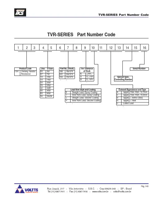
TVR 07 180 TVR 07 220 TVR 07 270 TVR 07 330 TVR 07 390 TVR 07 470 TVR 07 560 TVR 07 680 TVR 07 820 TVR 07 101 TVR 07 121 TVR 07 151 TVR 07 181 TVR 07 201 TVR 07 221 TVR 07 241 TVR 07 271 TVR 07 301 TVR 07 331 TVR 07 361 TVR 07 391 TVR 07 431 TVR 07 471 TVR 07 511 TVR 07 561 TVR 07 621 TVR 07 681 TVR 07 751 TVR 07 821
K ±10% A 0~+10% B 0~-10% ::
Lead Wire Style and Coating S Straight Lead; Epoxy Coating I Inner Kink Lead; Epoxy Coating L Straight Lead; Silicone Coating P Inner Kink Lead; Silicone Coating ::
Serial Number
Special Spec. Controlling Number
Outward Appearance and Tape A Tapping Hole Pitch: 12.7mm E Tapping Hole Pitch: 15.0mm B Tapping + Ammo (Box) R Tapping + Reel C Cutted Lead ::
Rua Juquiá, 217 - Vila Antonieta - S.B.C. - Cep:09629-040 - SP - Brasil Tel: (11) 4367-7411 - Fax: (11) 4367-7416 - .br - voltts@.br
Pág. 3/43
元器件交易网
ZINC OXIDE VARISTOR 5Ø SERIES
POWER DERATING CURVE
Rua Juquiá, 217 - Vila Antonieta - S.B.C. - Cep:09629-040 - SP - Brasil Tel: (11) 4367-7411 - Fax: (11) 4367-7416 - .br - voltts@.br
元器件交易网
TVR-SERIES Part Number Code
TVR-SERIES Part Number Code
1 2 3 4 5 6 7 8 9 10 11 12 13 14 15 16
Product Code
TVR Thinking Varistor Resistance
Reference Capacitance
Dimensions
@1KHZ (pf) 3800 3600 3400 2900 1620 1550 1500 1200 900 750 620 500 400 360 310 290 260 230 210 190 180 160 150 140 130 120 110 100 90
395 510
420 560
465 615
510 670
Max. Clamping Voltage
Max. Energy
Vp (V) 36 43 53 65 77 93 110 135 135 165 200 250 300 340 360 395 455 500 550 595 650 710 775 845 930 1020 1120 1235 1355
1200
600
1200
600
1200
600
1200
6001Biblioteka 006001200
600
1200
600
1200
600
1200
600
1200
600
1200
600
1200
600
1200
600
Rated Power
(W) 0.02 0.02 0.02 0.02 0.02 0.02 0.02 0.02 0.25 0.25 0.25 0.25 0.25 0.25 0.25 0.25 0.25 0.25 0.25 0.25 0.25 0.25 0.25 0.25 0.25 0.25 0.25 0.25 0.25
Disc Ø Size 05 5Ø 07 7Ø 10 10Ø 14 14Ø 20 20Ø 25 25Ø 32 32Ø 40 40Ø 60 60Ø 34 34x34