Extended Abstract Mappings from real vectors to real vectors {
基于散乱数据点的物体表面重建方法的研究的开题报告

基于散乱数据点的物体表面重建方法的研究的开题报告一、选题背景物体表面重建是计算机视觉领域中的一个重要研究方向,它在许多领域中都有广泛应用,例如工业制造、实物模型制作、遥感数据处理等。
随着三维扫描技术和传感器的发展,获取物体三维模型的数据点也变得更加容易和精确。
然而,仅仅由散乱的数据点去重建物体表面却是一项非常具有挑战性的任务。
目前,物体表面重建技术主要有两种方法:基于光学传感器的三维扫描方法和基于图像的结构光方法。
这些方法都能够获得大量的数据点,但是普遍存在粗糙、缺失、噪声等问题,直接应用表面重建算法会导致表面不光滑、有裂缝、缺失等不良影响。
因此,本文选题选取了基于散乱数据点的物体表面重建方法的研究,旨在通过先进的算法去解决表面重建中存在的问题,从而为物体表面重建提供更加可靠的解决方案。
二、研究目标本文研究的目标是提出一种基于散乱数据点的物体表面重建方法,解决表面重建中存在的粗糙、缺失、噪声等问题,以实现对物体表面的精确重建。
具体研究内容包括以下两个方面:1. 提出一种基于点云的重建算法,用于将散乱的数据点转化为连续的三维曲面,并确保表面的连续性和光滑性。
同时,还需要考虑加速算法的运行速度,尽可能地节约计算资源。
2. 针对现有的一些表面重建算法存在的问题,例如缺失、噪声等,提出一些改进措施,以提高表面重建的精度和可靠性。
三、论文结构本文的研究内容和结构如下:第一章:绪论。
首先介绍物体表面重建的背景和意义,阐述研究意义和研究目标,最后概括本文的研究内容和结构。
第二章:物体表面重建技术概述。
介绍物体表面重建的基本流程、常用方法、技术难点及其解决方案,为后续章节的算法提供理论基础。
第三章:基于点云的物体表面重建算法。
此章节提出一种基于点云的重建算法,包括点云内插、曲面拟合、去噪等过程,以及加速算法的实现。
第四章:改进的物体表面重建算法。
此章节提出几种改进措施,包括图像纹理映射、多尺度重建、全局和局部优化等方法,以提高表面重建的精度和可靠性。
java abstractvariadicfunction函数 -回复

java abstractvariadicfunction函数-回复Java是一种面向对象的编程语言,具有许多强大的功能和特性,其中之一是它的抽象可变参数函数(Abstract Variadic Function)。
抽象可变参数函数是指可以接受不确定数量的参数并且在函数中以数组的形式进行处理。
在本文中,我们将逐步介绍如何在Java中创建和使用抽象可变参数函数。
首先,让我们来了解一下为什么抽象可变参数函数在Java中非常有用。
使用抽象可变参数函数,我们可以在不事先确定参数数量的情况下编写更加灵活和可扩展的代码。
这意味着我们可以在调用函数时传递任意数量的参数,并且函数可以自动将这些参数组合成一个数组来进行处理。
这对于处理不确定数量的输入非常方便,尤其是在我们需要编写通用的函数时。
为了创建一个抽象可变参数函数,我们需要使用省略号(Ellipsis)作为参数的类型,并给参数一个名称。
下面是一个示例:javapublic void abstractVariadicFunction(String... params) { 处理参数的代码}在这个示例中,我们创建了一个名为abstractVariadicFunction的函数,它接受一个名为params的可变参数。
params参数可以是任意数量的字符串参数,并且在函数中将以数组的形式进行处理。
现在,让我们来看看如何在函数内部使用这些可变参数。
由于params参数是一个数组,我们可以使用for循环或者其他数组操作来处理这些参数。
以下是一个示例:javapublic void abstractVariadicFunction(String... params) {for (String param : params) {System.out.println(param);}}在这个示例中,我们遍历params数组并打印出数组中的每个元素。
我们可以调用这个函数并传递任意数量的参数,所有的参数都将被打印出来。
Invited Lecture

8.4 ER-schemes
9 Conclusions and further research
We have introduced the use of translation schemes into database design theory. We have shown how they capture disparate notions such as information preservation and dependency preservation in a uniform way. We have shown how they relate to normal form theory and have stated what we think to be the Fundamental Problem of Database Design. Several resulting research problems have been explicitly stated in the paper. We have shown that the Embedded Implicational Dependencies are all needed, when we deal with stepwise re nements of database schemes speci ed by Functional and Inclusion Dependencies. As the material presented grew slowly while teaching database theory, its foundational and didactic merits should not be underestimated. Over the years our students of the advanced database theory course con rmed our view that traditional database design lacks coherence and that this approach makes many issues accessible to deeper understanding. Our approach via dependency preserving translation{re nements can be extended to a full edged design theory for Entity{Relationship design or, equivalently, for database schemes in ER-normal form, cf. MR92]. It is also the appropriate framework to compare transformations of ER-schemes and to address the Fundamental Problem of ER{Database Design. Translation schemes can also be used to deal with views and view updates, as views are special cases of translation schemes. The theory of complementary views from BS81] can be rephrased elegantly in this framework. It is connected with the notion of translation schemes invariant under a relation and implicit denability, Kol90]. Order invariant translation schemes play an important role in descriptive complexity theory, Daw93] and Mak94]. The theory of independent complementary views of KU84] exhibits some severe limitations on the applicability of BS81]. In spite of these limitations it seems worthwhile to explore the connection between independent views and transformation invariant for certain relations further. The latter two applications are currently being developed by the authors and their students and will be included in the full paper.
Bluelighttec BBLL66880000BB 多功能多技术测试平台说明书

B l u e S c o p e B L6800BHandheld multi‐functional, multi‐technology test platform forEthernet, IP, SONET/SDH/PDH, OTN & Fibre ChannelKey BlueScope Benefits:∙Unmatchable market performance▪Test up to 32‐Mulistreams each with customizable traffic profiles.▪Powerful Packet Flooding. Flood nearly any field of a packet including MAC, VLAN, MPLS with Layer 3 & 4 payload options.▪Dual port Packet Capture and Analysis utilizing WireShark engine▪The most compact OTN tester on the market. Supports OTU‐1/2▪Unparalleled physical layer testing on all optical transport methods and line rates.∙Software license controlled features for upgrades or maintaining test standards as they are defined, then certified.▪Instant (DIY) remote/field upgradable; via a software only license key.▪Never lose a test capability/feature due to lost, forgotten, or damaged hardware modules.∙Linux Operating System▪Less susceptibility to viruses and malware. Known in the IT industry for being more stable than alternatives.Linux the OS choice for hand held testers and utilized in the Bluescope!BlueScope Highlights:∙Handheld test set hardware platform that supports both 1/10 GbE Ethernet, SONET/SDH/PDH, Fiber Channel, OTN, WLAN.∙Rapid Boot‐up∙Eight Hours battery stand time and approximate four hours of battery test time.∙Remote control through VNC and a CLI.∙Dual port operation enables performing two tests simultaneously∙Bluetooth support to easily offload test results or transfer test configurations.∙Customizable platform. Avoids technology obsolescence. Choose your ports, line rates and testing options you require now. Then invest in what you require. Bluescope is upgradeable for your future testing by you and can be fullyconfigured by you, whenever your test requirements, testing demands, financial position changes. Just add ports, features, and software options etc. in the future. Truly “pay as you grow” handheld test platform.Ethernet & IPBlueScope Ethernet Features: ∙Loopback Mode (auto, smart, 802.3ah standard)∙Throughput Test (Multi‐Stream)∙Packet Filtering∙IP Tools (Ping, DHCP, Trace Route)∙In‐Service Traffic Monitoring (Non‐Intrusive Mode)∙MPLS (stacking up to 3 MPLSs)∙VLAN, Q‐in‐Q (up to 3 VLANs)∙Remote Control via VNC/CLI∙Report Generation (PDF, CSV and TXT)∙RFC2544 (Network Equipment Benchmarking Test)∙Packet Capture/Decode via WireShark∙Throughput 32 multi‐streams∙Packet Flooding – Mac/VLAN/IP/User Defined Field∙L1/Unframed BERT (Cable BERT, Unframed BERT)∙Network Discovery∙100 FX/LX (Optic)∙Y.1564(EtherSAM)∙PBB/PBB‐TE(MAC‐in‐MAC)∙SyncE/1588∙IPV6∙Asymmetric RFC2544 Testing∙One‐Way Delay Measurement using 1588 or GPS∙CLI Interface∙10GbE WAN PHY∙WLAN 802.11 a/b/g TestingEthernet & IP Ethernet IP Applications∙Troubleshoots Ethernet/IP networks, captures and analyzes packets, and identifies network problems.∙Tests Carrier Ethernet transport to verify class of service (CoS), Triple‐Play Service, and Ethernet circuit transparency.∙Supports Packet Transport Network (PTN) testing with MPLS‐TP traffic generation and QoS analysis, along with simultaneous verification of OAM Label 13 or 14 operation.∙Confirms higher‐layer Ethernet data applications and services at 10Mbps to 1Gbps rates with Ipv4 and IPv6∙Tests Layer 1‐4 Ethernet/IP SLAs with RFC 2544 for up to 3 VLAN tags, Q‐in‐Q, and MPLS encapsulation.∙Verifies automatically SLA compliance according to Y.1564, including different traffic profiles per service, and KPI compliance for all committed services concurrently.Ethernet IP Testing LifecycleInstallation∙RFC2544, including frame delay variation, asymmetric rates, and concurrent results to reduce overall test time.∙Y.1564 EtherSAM automated SLA validation including bandwidth profiles and KPI compliance for quickly verifying multiple services.∙Carrier Ethernet testing with PBB, MPLS, MPLS‐TP, VLAN and Q‐in‐Q.Troubleshooting∙Line rate packet capture up to 10Gbps.∙Packet decodes with integrated WireSharkCarrier Ethernet Installation TestingFor years Ethernet/IP has been transported throughout carrier networks encapsulated in other data‐link layer technologies thatevolved into a carrier‐grade technology because of operations, administration, and maintenance (OAM) standards such as ITU‐Ty.1731, IEEE 802.1ag, and 802.3ah. Ethernet now possesses many of the characteristics that made SONET/SDH the transporttechnology of choice; end‐to‐end circuit transparency, redundancy, and full‐featured OAM for circuit‐based performancemanagement and alarming. The BlueScope delivers a much‐needed tool set for provisioning and troubleshooting Ethernet networksthat substantially improves installation and troubleshooting times, thereby granting error‐free operation and a significant reductionin operating expense.RFC2544 TestingThe BlueScope delivers all the Carrier Ethernet testing needed to qualify Ethernet‐based transport networks. RFC2544 is the defacto industry standard for Ethernet circuit installation. In addition to supporting Ethernet throughput or committed information rate (CIR), frame delay (FD) or latency, frame loss (FLR), and back‐to‐back burst testing as called out in the RFC, the BlueScope also tests forpacket jitter or frame delay variation (FDV) to ensure the circuit is ready to transport time‐sensitive services such as IPTV and VoIP.Using a pair of test sets and Asymmetric RFC testing, users can validate Ethernet Virtual Circuits (EVCs) with different upstream and downstream CIRs, or they can test sequentially in both directions to ensure that key performance indicators (KPIs) are met acrossany connection type.ITU‐T Y.1564 EtherSAM Service Activation TestingY.1564 EtherSAM allows for fast and easy verification of SLAs for differentiated services including validation of different bandwidthprofiles like committed information rate (CIR), extended information rate (EIR) and maximum bandwidth. Pass / Fail results for KPIs including CIR, frame delay (FD), frame delay variation (FDV or packet jitter) and frame loss rate (FLR) are provided independently forup to 16 services. Out of sequence frames and available seconds are reported per Y.1564.Ethernet & IPVerifying CoS with Multiple StreamsMulti‐stream testing generates several streams of traffic at the Ethernet, IP, and TCP/UDP layers (Layers 2‐4) to emulate various types of traffic with the appropriate CoS mappings so that users can assess the impact of traffic prioritization on the overall network architecture while confirming proper network element queuing, policing, and shaping. Up to 32 individually configured streams enable generation and analysis of per stream key parameters such as VLAN ID and priority, TOS/DSCP marking, packet size,source/destination IP and MAC address, and source/destination TCP/UDP ports. Users can configure constant or ramp traffic to simulate near real‐world traffic before actually delivering a service. This level of testing confirms the network design as well as drastically reduces post‐installation troubleshooting.BER and Latency TestingThe BlueScope supports optical Layer 1 (L1) BER testing for stress testing the underlying physical transport link. A standard 2^23 pattern is used to obtain key QoS measurements including bit error rates, pattern sync, latency, line coding, and signal/power levels.Ethernet OAM, VLAN, Q‐inQ, MPLS and PBB Tunneling TechnologiesEthernet tagging and encapsulation is commonly used to improve the scalability of Ethernet networks by isolating customer traffic and, in the case of provider backbone bridging (PBB), minimizing the number of MAC addresses that equipment must learn. Regardless of the encapsulation and tagging used, the BlueScope tests CoS to confirm KPIs such as CIR, FD, FDV, and FLR. Support for virtual local area network (VLAN) tags, Q‐in‐Q VLAN tags, PBB (also known as MAC‐in‐MAC) and multi‐protocol label switching (MPLS), the BlueScope allows testing at any part of the Metro network.Ethernet Timing Synchronization Verification using 1588v2 PTP and G.826x SyncECritical network timing and frequency synchronization testing enables service providers to analyze emerging 1588v2 PTP and Synchronous Ethernet (SyncE) protocols greatly reducing expenses for mobile backhaul and LTE by eliminating the need forTDM/GPS. Wireless backhaul providers can now verify whether Ethernet links can transfer PTP protocols by connecting to a PTP master and measuring critical packet parameters such as PDV with simultaneous network traffic loading. SyncE testing recovers the timing of an incoming Ethernet interface for the tester’s transmitter. Capturing and decoding the 1588v2 PTP and Ethernet Synchronization Messaging Channel (ESMC) messages allows operators to verify and troubleshoot proper configuration and operation of synchronization networks.Carrier Ethernet Fault IsolationIn the ever‐changing Ethernet and IP world providers must quickly, cost‐efficiently, and reliably troubleshoot problems at all layers of the stack. The BlueScope provides powerful line‐rate packet capture at Ethernet speeds up to 1GigE without dropping a single packet. When troubleshooting problems occur intermittently or inconsistently, it supports multiple traffic filters and triggers, including 16‐byte pattern identification, to isolate the exact problem and minimize the amount of information gathered.The BlueScope natively supports WireShark for on‐instrument packet decode. Additionally, users can save the captured traffic in a standard pcap file format and export it via USB or FTP through the management port for further analysis.SONET/SDH/PDHThe BlueScope 6800B performs BER testing on all line interfaces in end‐to‐end or loopback applications, inserts errors and alarms to verify NE conformance and connectivity, and measures BERs from DS1 (1.5M)/E1 (2.048M) rates to OC‐192/STM‐64.MappingsSONET/SDH mappings include all intermediate mappings down to VC‐4/VC‐3 in addition to BERT payload with multiple PRBS choices.SONET/SDH/PDH Overhead Byte Manipulation and AnalysisUsing the overhead byte manipulation and analysis capability, users can modify K1 and K2 bytes to test automatic protection switching (APS) to specify and identify user‐configurable path trace messages and payloads. The path overhead (POH) capture feature facilitates troubleshooting end‐to‐end problems. The Bluescope 6800B supports manual capture, capture on alarm, and capture based on user‐defined triggersPhysical Layer TestingPerform physical layer testing to verify dark fiber and line continuity across all optical transport methods and line rates. Support for unframed STM‐1/4/16/64, Fiber Channel 1x/2x/4x/10x, OTN OTU‐1/2/1E/2E/1F/2F, 1.250G(1GE), 10.313(10GE) and 3.1G (CPRI).Service Disruption measurementsThe Bluescope 6800B measures the protection switch times of SONET/SDH rings and their effects on tributaries. By measuring various error and alarm conditions on the tributaries, providers can verify that their transport network is providing adequate redundancy to guarantee SLAs.Multi‐Channel ViewDrill down to view the path hierarchy in its entirety on one screen with automatic detection of payload type (concatenated or non‐concatenated) for SONET ( 48x STS‐1 and 28x VT 2/1.5) and SDH (48x AU‐3 and 28x TU12/TU11).Line Through ModeConnecting the test unit in‐line provides not only monitoring capabilities but also the possibility of injecting errors. This provides for an effective tool in serice‐disruption testing.SDH/PDH Alarm/Error GenerationGenerate Alarms for:LOS, LOF, OOF,RS‐TIM, MS‐AIS, MS‐RDI, AU‐LOP, AU‐AIS, TU‐LOP, TU‐AIS, HP‐UNEQ, HP‐PLM, HP‐TIM, HP‐RDI,HP‐SRDI, HP‐CRDI, HP‐PRDI, HP‐TC‐UNEQ, HP‐TC‐LOMF, HP‐TC‐AIS, HP‐TC‐RDI, HP‐TC‐ODI, LP‐UNEQ, LP‐PLM, LP‐TIM, LP‐RFI, LP‐RDI, LP‐SRDI, LP‐CRDI, LP‐PRDI, LP‐TC‐UNEQ, LP‐TC‐LOMF, LP‐TC‐AIS, LP‐TC‐RDI, LP‐TC‐ODIGenerate Errors for:FAS, B1, B2,B3, MS‐REI, BIT,HP‐REI, HP‐TC‐IEC, HP‐TC‐REI, HP‐TC‐OEI, LP‐BIP, LP‐REI, LP‐TC‐IEC, LP‐TC‐REI, LP‐TC‐OEIBlueScope SONET/SDH Options:∙(SO‐1) OC‐3/12/48 (STM 1/4/16)(SO‐2) OC‐192 (STM‐64)(SO‐3) OC‐3/12/48/192 (STM 1/4/16/64)∙(SO‐4) Unframed Line Rate (Requires SO‐1,2 or 3)∙(SO‐5) Multi‐Channel View (Requires SO‐1, 2 or 3)∙(SO‐6) Signal Delay emulator (injection of signal delay in unframed line rates; Requires SO‐4)BlueScope PDH Options: ∙(PD‐1)E1/T1 (DS1)(PD‐2)E3/T3 (DS3)(PD‐3)E1/T1 and E3/T3OTNOTN is the next generation network designed to combine and accelerate the benefits of SDH/SONET with the bandwidth expandability of DWDM (Dense wavelength division multiplexing).Test end‐to‐end connectivity by transmitting and receiving OTN signals with the ability to insert and analyze errors and alarms in network troubleshooting and equipment verification applications.TCM with Error/Alarm detectionVerify network element interoperability with the TCM bytes; Count, current rate and average rate for each error, SDT (Service disruption Time) measurements and RTD (Round Trip Delay) measurements. Verify OTN alarms and errors with injection capabilities such as loss of frame (LOF), alarm indication signal (AIS), and backward defect indication (BDI).FEC TestingTransmit and analyze correctable and uncorrectable FEC errors to verify a network element’s ability to correct conditions through the use of FEC enabled signals. Correctable and uncorrectable FEC error positions are accumulated and monitored through a graphical hierarchy window which allows users to easily recognize the position of the FEC error.Features programmable FEC error generation functions that allows the user to define a detailed position for correctable FEC errors and un‐correctable FEC errors.Line Through ModeConnecting the test unit in‐line provides not only monitoring capabilities but also the possibility of injecting errors. This provides for an effective tool in service‐disruption testing.BlueScope OTN Options:∙(OT‐1)OTU‐1 (2.66G/STM‐16) Requires SO‐1(OT‐2)OTU‐2 (10.7G/STM‐64) Requires SO‐2(OT‐3)OTU‐1/2 (2.66G & 10.7G / STM‐16 & STM‐64) Requires SO‐3Fibre ChannelThe BlueScope B6800B tests 1x, 2x, 4x and 10x Gbps Fibre Channel (FC). Users can manipulate various fields of the FC frames to emulate end customer traffic and perform BER measurements on L1 and L2 circuits. The BlueScope supports buffer crediting capability, which lets providers verify the effect of delay on the link throughput and test the ability of the link to obtain the optimum buffer credit values. The BlueScope also allows users to turn up storage area networks (SANs), producing reliable throughput, packet loss, RTD, and burstability results with consistent test methodology.BlueScope Fiber Channel Options:∙(FC‐1) Fiber Channel 1x/2x(FC‐2) Fiber Channel 4x(FC‐3)Fiber Channel 1x/2x/4xFiber Test Tools (Optic microscope inspector)The fiber microscope inspect and analyze the end‐face of connector through USB interface.Hardware Specifications:∙Ports:▪(2) SFPs (1000BASE‐SX/LX/ZX, 100‐FX/LX/SX)▪(2) 10/100/1000Base‐T (RJ45)▪(1) XFP▪(1) BNC connectors (Tx/Rx) 34‐45M▪(1) Bantam(Tx/Rx) : 1.5M ‐ 2M▪(1) SMA(Tx) : Tx Reference Clock Out▪(1) SMA: External clock input 1.544 ‐2.048 Mbps / 1.544m, 2.048 m, 10M / Any clock speed▪(1) GPS Signal input▪(1) HDMI output▪(1) 3.5mm headset audio jack and mic support.∙Dimensions:▪Size: 172.5 (W) x 227 (H) x 58.5 (D) mm▪Weight: 1.3 kg with Battery, Battery (0.3 kg)∙Operating Temp: 0Ԩ~40Ԩ∙Storage Temp: ‐20Ԩ~ +70Ԩ∙Display: 5.7 Color TFT‐LCD Touch Screen∙User Interface: Touch Screen & Keypad∙Humidity: 10% ~ 90%∙Power:▪AC adaptor: 100V~240 V(50Hz/60Hz)▪Removable/Rechargeable lithium ‐Ion Battery▪Battery life: 3 hours typical, 8 hour in standby mode∙Memory:▪128GByte internal Flash memory includedContact Information:Web: US & Canada:Support: ************************Tel: +1 408 841 9689Sales: **********************Fax: +1 408 841 9607。
Google开源激光SLAM算法论文原文

As-built floor plans are useful for a variety of applications. Manual surveys to collect this data for building management tasks typically combine computed-aided design (CAD) with laser tape measures. These methods are slow and, by employing human preconceptions of buildings as collections of straight lines, do not always accurately describe the true nature of the space. Using SLAM, it is possible to swiftly and accurately survey buildings of sizes and complexities that would take orders of magnitude longer to survey manually.
1All authors are at Google.
loop closure detection. Some methods focus on improving on the computational cost by matching on extracted features from the laser scans [4]. Other approaches for loop closure detection include histogram-based matching [6], feature detection in scan data,and using machine learning [7].
学习显示高动态范围的图像
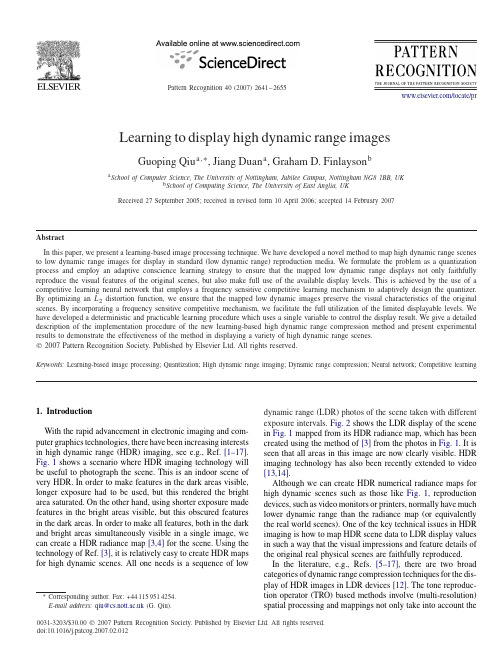
Pattern Recognition 40(2007)2641–2655/locate/prLearning to display high dynamic range imagesGuoping Qiu a ,∗,Jiang Duan a ,Graham D.Finlayson ba School of Computer Science,The University of Nottingham,Jubilee Campus,Nottingham NG81BB,UKb School of Computing Science,The University of East Anglia,UKReceived 27September 2005;received in revised form 10April 2006;accepted 14February 2007AbstractIn this paper,we present a learning-based image processing technique.We have developed a novel method to map high dynamic range scenes to low dynamic range images for display in standard (low dynamic range)reproduction media.We formulate the problem as a quantization process and employ an adaptive conscience learning strategy to ensure that the mapped low dynamic range displays not only faithfully reproduce the visual features of the original scenes,but also make full use of the available display levels.This is achieved by the use of a competitive learning neural network that employs a frequency sensitive competitive learning mechanism to adaptively design the quantizer.By optimizing an L 2distortion function,we ensure that the mapped low dynamic images preserve the visual characteristics of the original scenes.By incorporating a frequency sensitive competitive mechanism,we facilitate the full utilization of the limited displayable levels.We have developed a deterministic and practicable learning procedure which uses a single variable to control the display result.We give a detailed description of the implementation procedure of the new learning-based high dynamic range compression method and present experimental results to demonstrate the effectiveness of the method in displaying a variety of high dynamic range scenes.᭧2007Pattern Recognition Society.Published by Elsevier Ltd.All rights reserved.Keywords:Learning-based image processing;Quantization;High dynamic range imaging;Dynamic range compression;Neural network;Competitive learning1.IntroductionWith the rapid advancement in electronic imaging and com-puter graphics technologies,there have been increasing interests in high dynamic range (HDR)imaging,see e.g.,Ref.[1–17].Fig.1shows a scenario where HDR imaging technology will be useful to photograph the scene.This is an indoor scene of very HDR.In order to make features in the dark areas visible,longer exposure had to be used,but this rendered the bright area saturated.On the other hand,using shorter exposure made features in the bright areas visible,but this obscured features in the dark areas.In order to make all features,both in the dark and bright areas simultaneously visible in a single image,we can create a HDR radiance map [3,4]for the ing the technology of Ref.[3],it is relatively easy to create HDR maps for high dynamic scenes.All one needs is a sequence of low∗Corresponding author.Fax:+441159514254.E-mail address:qiu@ (G.Qiu).0031-3203/$30.00᭧2007Pattern Recognition Society.Published by Elsevier Ltd.All rights reserved.doi:10.1016/j.patcog.2007.02.012dynamic range (LDR)photos of the scene taken with different exposure intervals.Fig.2shows the LDR display of the scene in Fig.1mapped from its HDR radiance map,which has been created using the method of [3]from the photos in Fig.1.It is seen that all areas in this image are now clearly visible.HDR imaging technology has also been recently extended to video [13,14].Although we can create HDR numerical radiance maps for high dynamic scenes such as those like Fig.1,reproduction devices,such as video monitors or printers,normally have much lower dynamic range than the radiance map (or equivalently the real world scenes).One of the key technical issues in HDR imaging is how to map HDR scene data to LDR display values in such a way that the visual impressions and feature details of the original real physical scenes are faithfully reproduced.In the literature,e.g.,Refs.[5–17],there are two broad categories of dynamic range compression techniques for the dis-play of HDR images in LDR devices [12].The tone reproduc-tion operator (TRO)based methods involve (multi-resolution)spatial processing and mappings not only take into account the2642G.Qiu et al./Pattern Recognition 40(2007)2641–2655Fig.1.Low dynamic range photos of an indoor scene taken under different exposureintervals.Fig.2.Low dynamic display of high dynamic range map created from the photos in Fig.1.The dynamic range of the radiance map is 488,582:1.HDR radiance map synthesis using Paul Debevec’s HDRShop software (/HDRShop/).Note:the visual artifacts appear in those blinds of the glass doors were actually in the original image data and not caused by the algorithm.values of individual pixel but are also influenced by the pixel spatial contexts.Another type of approaches is tone reproduc-tion curve (TRC)based.These approaches mainly involve the adjustment of the histograms and spatial context of individual pixel is not used in the mapping.The advantages of TRO-based methods are that they generally produce sharper images when the scenes contain many detailed features.The problems with these approaches are that spatial processing can be computa-tionally expensive,and there are in general many parameters controlling the behaviors of the operators.Sometimes these techniques could introduce “halo”artifacts and sometimes they can introduce too much (artificial)detail.TRC-based methods are computationally simple.They preserve the correct bright-ness order and therefore are free from halo artifacts.These methods generally have fewer parameters and therefore are eas-ier to use.The drawbacks of this type of methods are that spa-tial sharpness could be lost.Perhaps one of the best known TRC-based methods is that of Ward and co-workers’[5].The complete operator of Ref.[5]also included sophisticated models that exploit the limita-tions of human visual system.According to Ref.[5],if one just wanted to produce a good and natural-looking display for an HDR scene without regard to how well a human ob-server would be able to see in a real environment,histogram adjustment may provide an “optimal”solution.Although the histogram adjustment technique of Ref.[5]is quite effective,it also has drawbacks.The method only caps the display contrast(mapped by histogram equalization)when it exceeds that of the original scene.This means that if a scene has too low contrast,the technique will do nothing.Moreover,in sparsely populated intensity intervals,dynamic range compression is achieved by a histogram equalization technique.This means that some sparse intensity intervals that span a wide intensity range will be com-pressed too aggressively.As a result,features that are visible in the original scenes would be lost in the display.This un-satisfactory aspect of this algorithm is clearly illustrated in Figs.9–11.In this paper,we also study TRC-based methods for the dis-play of HDR images.We present a learning-based method to map HDR scenes to low dynamic images to be displayed in LDR devices.We use an adaptive learning algorithm with a “conscience”mechanism to ensure that,the mapping not only takes into account the relative brightness of the HDR pixel val-ues,i.e.,to be faithful to the original data,but also favors the full utilization of all available display values,i.e.,to ensure the mapped low dynamic images to have good visual contrast.The organization of the paper is as follows.In the next section,we cast the HDR image dynamic range compression problem in an adaptive quantization framework.In Section 3,we present a solution to HDR image dynamic range compression based on adaptive learning.In Section 4,we present detailed imple-mentation procedures of our method.Section 4.1presents re-sults and Section 4.2concludes our presentation and briefly discusses future work.2.Quantization for dynamic range compressionThe process of displaying HDR image is in fact a quantiza-tion and mapping process as illustrated in Fig.3.Because there are too many (discrete)values in the high dynamic scene,we have to reduce the number of possible values,this is a quantiza-tion process.The difficulty faced in this stage is how to decide which values should be grouped together to take the same value in the low dynamic display.After quantization,all values that will be put into the same group can be annotated by the group’s index.Displaying the original scene in a LDR is simply to rep-resent each group’s index by an appropriate display intensity level.In this paper,we mainly concerned ourselves with the first stage,i.e.,to develop a method to best group HDR values.Quantization,also known as clustering,is a well-studied subject in signal processing and neural network literature.Well-known techniques such as k -means and various neural network-based methods have been extensively researched [18–21].Let x(k),k =1,2,...,be the intensities of the luminance compo-nent of the HDR image (like many other techniques,we only work on the luminance and in logarithm space,also,we treatG.Qiu et al./Pattern Recognition 40(2007)2641–26552643QuantizationInputHigh dynamic range data (real values)1x xMappingDisplaying Intensity LevelsFig.3.The process of display of high dynamic range scene (from purely anumerical processing’s point of view).each pixel individually and therefore are working on scalar quantization).A quantizer is described by an encoder Q ,which maps x(k)to an index n ∈N specifying which one of a small collection of reproduction values (codewords)in a codebook C ={c n ;n ∈N }is used for reconstruction,where N in our case,is the number of displayable levels in the LDR image.There is also a decoder Q −1,which maps indices into reproduction values.Formally,the encoding is performed as Q(x(k))=n if x(k)−c n x(k)−c i ∀i (1)and decoding is performed as Q −1(n)=c n .(2)That is (assuming that the codebook has already been de-signed),an HDR image pixel is assigned to the codeword that is the closest to it.All HDR pixels assigned to the same code-words then form a cluster of pixels.All HDR pixels in the same cluster are displayed at the same LDR level.If we order the codewords such that they are in increasing order,that is c 1<c 2<···<c N −1<c N ,and assign display values to pixels belonging to the clusters in the order of their codeword values,then the mapping is order preserving.Pixels belonging to a clus-ter having a larger codeword value will be displayed brighter than pixels belonging to a cluster with a codeword having a smaller value.Clearly,the codebook plays a crucial role in this dynamic range compression strategy.It not only determines which pix-els should be displayed at what level,it also determines which pixels will be displayed as the same intensity and how many pixels will be displayed with a particular intensity.Before we discuss how to design the codebook,lets find out what require-ments for the codebook are in our specific application.Recall that one of the objectives of mapping are that we wish to preserve all features (or as much as possible)of the HDR image and make them visible in the LDR reproduction.Because there are fewer levels in the LDR image than in the HDR image,the compression is lossy in the sense that there will be features in the HDR images that will be impossible to reproduce in the LDR images.The question is what should bepreserved (and how)in the mapping (quantization)in order to produce good LDR displays.For any given display device,the number of displayable lev-els,i.e.,the number of codewords is fixed.From a rate dis-tortion’s point of view,the rate of the quantizer is fixed,and the optimal quantizer is the one that minimizes the distortion.Given the encoding and decoding rules of Eqs.(1)and (2),the distortion of the quantizer is defined asE =i,ki (k) x(k)−c i where i (k)=1if x(k)−c i ≤ x(k)−c j ∀j,0otherwise .(3)A mapping by a quantizer that minimizes E (maximizes rate distortion ratio)will preserve maximum relevant information of the HDR image.One of the known problems in rate distortion optimal quan-tizer design is the uneven utilization of the codewords where,some clusters may have large number of pixels,some may have very few pixels and yet others may even be empty.There may be two reasons for this under utilization of codewords.Firstly,the original HDR pixel distribution may be concentrated in a very narrow range of intensity interval;this may cause large number of pixels in these densely populated intervals to be clustered into a single or very few clusters because they are so close together.In the HDR image,if an intensity interval has a large concentration of pixels,then these pixels could be very important in conveying fine details of the scene.Although such intervals may only occupy a relatively narrow dynamic range span because of the high-resolution representation,the pixels falling onto these intervals could contain important de-tails visible to human observers.Grouping these pixels together will loose too much detail information.In this case,we need to “plug”some codewords in these highly populated intensity intervals such that these pixels will be displayed into different levels to preserve the details.The second reason that can cause the under utilization of codewords could be due to the opti-mization process being trapped in a local minimum.In order to produce a good LDR display,the pixels have to be reasonably evenly distributed to the codewords.If we assign each code-word the same number of pixels,then the mapping is histogram equalization which has already been shown to be unsuitable for HDR image display [5].If we distribute the pixel popula-tion evenly without regarding to their relative intensity values,e.g.,grouping pixels with wide ranging intensity values just to ensure even population distribution into each codeword,then we will introduce too much objectionable artifacts because compression is too aggressive.In the next section,we intro-duce a learning-based approach suitable for designing dynamic range compression quantizers for the display of HDR images.3.Conscience learning for HDR compressionVector quantization (VQ)is a well-developed field [16](although we will only design a scalar quantizer (SQ),we will borrow techniques mainly designed for VQ.There are2644G.Qiu et al./Pattern Recognition40(2007)2641–2655 many methods developed for designing vector quantizers.Thek-means type algorithms,such as the LBG algorithm[18],and neural network-based algorithms,such as the Kohonenfeature map[19]are popular tools.As discussed in Section2,our quantizer should not only be based on the rate distortioncriterion,but also should ensure that there is an even spreadof pixel population.In other words,our quantizer should min-imize E in Eq.(3)and at the same time the pixels should beevenly distributed to the codewords.Therefore the design algo-rithm should be able to explicitly achieve these two objectives.In the neural network literature,there is a type of consciencecompetitive learning algorithm that will suit our application.Inthis paper,we use the frequency sensitive competitive learning(FSCL)algorithm[20]to design a quantizer for the mappingof HDR scenes to be displayed in low dynamic devices.Tounderstand why FSCL is ideally suited for such an application,wefirst briefly describe the FSCL algorithm.The philosophy behind the FSCL algorithm is that,when acodeword wins a competition,the chance of the same codewordwinning the next time round is reduced,or equivalently,thechance of other codewords winning is increased.The end effectis that the chances of each codeword winning will be equal.Putin the other way,each of the codewords will be fully utilized.In the context of using the FSCL for mapping HDR data tolow dynamic display,the limited number of low dynamic levels(codewords)will be fully utilized.The intuitive result of fullyutilized display level is that the displayed image will have goodcontrast,which is exactly what is desired in the display.How-ever,unlike histogram equalization,the contrast is constrainedby the distribution characteristics of the original scene’s inten-sity values.The overall effect of such a mapping is thereforethat,the original scenes are faithfully reproduced,while at thesame time,the LDR displays will have good contrast.FSCL algorithmStep1:Initialize the codewords,c i(0),i=1,2,...,N,to ran-dom numbers and set the counters associated with each code-word to1,i.e.f i(0)=1,i=1,2,...,NStep2:Present the training sample,x(k),where k is thesequence index,and calculate the distance between x(k)andthe codewords,and subsequently modify the distances usingthe counters valuesd i(k)= x(k)−c i(k) d∗i(k)=f i(k)d i(k)(4)Step3:Find the winner codeword c j(k),such thatd∗j(k) d∗i(k)∀iStep4:Update the codeword and counter of the winner asc j(k+1)=c j(k)+ (x(k)−c j(k))f j(k+1)=f j(k)+1where0< <1(5)Step5:If converged,then stop,else go to Step2.The FSCL process can be viewed as a constrained optimiza-tion problem of the following form:J=E+iki(k)−|x(k)|N2,(6)where is the Lagrange multiplier,|x(k)|represents the totalnumber of training samples(pixels),N is the number of code-words(display levels),E and are as defined in Eq.(3).Minimizing thefirst term ensures that pixel values close toeach other will be grouped together and will be displayed asthe same single brightness.Minimizing the second term facil-itates that each available displayable level in the mapped im-age will be allocated similar number of pixels thus creating awell contrast display.By sorting the codewords in an increasingorder,i.e.,c1<c2<···<c N−1<c N,the mapping also ensuresthat the brighter pixels in the original image are mapped to abrighter display level and darker pixels are mapped to a darkerdisplay level thus ensuring the correct brightness order to avoidvisual artifacts such as the“halo”phenomenon.Because the mapping not only favors an equally distributedpixel distribution but also is constrained by the distancesbetween pixel values and codeword values,the current methodis fundamentally different from both traditional histogramequalization and simple quantization-based methods.His-togram equalization only concerns that the mapped pixels haveto be evenly distributed regardless of their relative brightness,while simple quantization-based mapping(including many lin-ear and nonlinear data independent mapping techniques,e.g.,Ref.[2])only takes into account the pixel brightness valuewhile ignoring the pixel populations in each mapped level.As a result,histogram equalization mapping will create visu-ally annoying artifacts and simple quantization-based methodwill create mappings with under utilized display levels whichoften resulting in many features being squashed and becomeinvisible.With FSCL learning,we could achieve a balancedmapping.4.Implementation detailsBecause the objective of our use of the FSCL algorithm inthis work is different from that of its ordinary applications,e.g.,vector quantization,there are some special requirementsfor its implementation.Our objective is not purely to achieverate distortion optimality,but rather should optimize an ob-jective function of the form in Eq.(6)and the ultimate goalis,of course,to produce good LDR displays of the HDR im-ages.In this section,we will give a detailed account of itsimplementation.4.1.Codebook initializationWe work on the luminance component of the image only andin logarithm space,from thefloating point RGB pixel valuesof the HDR radiance map,we calculateL=log(0.299∗R+0.587∗G+0.114∗B),L max=MAX(L),L min=MIN(L).(7)In using the FSCL algorithm,we found that it is very importantto initialize the codewords to linearly scaled values.Let thecodebook be C={c i;i=1,2,...,N},N is the number ofcodewords.In our current work,N is set to256.The initialG.Qiu et al./Pattern Recognition 40(2007)2641–26552645020004000600080001000012000133659712916119322505000100001500020000250000326496128160192224petitive learning without conscience mechanism will produce a mapping close to linear scaling.Left column:competitive learning without conscience mechanism.Right column:linear scaling.Radiance map data courtesy of Fredo Durand.values of the codewords are chosen such that they are equally distributed in the full dynamic range of the luminance:c i (0)=L min +i256(L max −L min ).(8)Recall that our first requirement in the mapping is that the dis-play should reflect the pixel intensity distribution of the original image.This is achieved by the optimization of E in Eq.(3)with the initial codeword values chosen according to Eq.(8).Let us first consider competitive learning without the conscience mechanism.At the start of the training process,for pixels falling into the interval c i (0)±(L max −L min )/512,the same code-word c i will win the competitions regardless of the size of pixel population falling into the interval.The pixels in the intensity intervals that are far away from c i will never have the chance to access it.In this case,distance is the only criterion that de-termines how the pixels will be clustered and pixel populations distributed into the codewords are not taken into account.Af-ter training,the codewords will not change much from their initial values because each codeword will only be updated by pixels falling close to it within a small range.In the encodingor mapping stage,since the codewords are quite close to their corresponding original positions which are linearly scattered in the FDR,the minimum distortion measure will make the map-ping approximately linear and extensive simulations demon-strate that this is indeed the case.As a result,the final mapped image will exhibit the pixel intensity distribution characteris-tics of the original image.Fig.4(a)shows a result mapped by competitive learning without the conscience mechanism,com-pared with Fig.4(b),the linearly scaled mapping result,it is seen that both the images and their histograms are very similar which demonstrate that by initializing the codewords according Eq.(8),optimizing the distortion function E in Eq.(3)has the strong tendency to preserve the original data of the original im-age.However,like linear compression,although the resulting image reflects the data distribution of the scene,densely pop-ulated intensity intervals are always over-quantized (too much compression)which causes the mapped image lacking contrast.With the introduction of the conscience mechanism,in the training stage,competition is based on a modified distance measure,d ∗in Eq.(4).Note that if a codeword wins the competitions frequently,its count and consequently its modi-2646G.Qiu et al./Pattern Recognition 40(2007)2641–2655σ = 0.05, η(0) = 0.1 σ = 0.05, η(0) = 0.2 010002000300040005000600070008000900006412819210002000300040005000600070008000064128192100020003000400050006000700006412819210002000300040005000600070000641281921000200030004000500060007000064128192σ = 0.05, η(0) = 0.3σ = 0.05, η(0) = 0.4σ = 0.05, η(0) = 0.5Fig.5.Final mapped images and their histograms for fixed and various (0).Radiance map data courtesy of Fredo Durand.fied distance increases,thus reducing its chance of being the winner and increasing the likelihood of other codewords with relatively lower count values to win.This property is exactly what is desired.If a codeword wins frequently,this means that the intensity interval it lies in gathers large population of pixels.In order to ensure the mapped image having goodG.Qiu et al./Pattern Recognition 40(2007)2641–26552647η(0) = 0.2, σ= 0.05 020004000600080000641281922000400060008000064128192100020003000400050006000700006412819210002000300040005000600070000641281921000200030004000500060007000064128192η(0) = 0.2, σ = 0.04 η(0) = 0.2, σ = 0.02η(0) = 0.2, σ = 0.0087η(0) = 0.2, σ = 0.002Fig.6.Final mapped images and their histograms for fixed (0)and various .Radiance map data courtesy of Fredo Durand.contrast,these densely populated intensity intervals should be represented by more codewords,or equivalently,more dis-play levels.The incorporation of the conscience mechanism makes the algorithm conscience of this situation and passes the chances to codewords with lower count values to win the com-petitions so that they can be updated towards the population dense intensity intervals and finally join in the quantization of these intervals.2648G.Qiu et al./Pattern Recognition40(2007)2641–2655 The training starts from linearly scattered codewords,withthe introduction of the conscience mechanism,the code-words are moved according to both their values and the pixelpopulation distribution characteristics.At the beginning of thetraining phase,the mapping is linear,and the mapped image’shistogram is narrow,as training progresses,the mapped im-age’s histogram is gradually wider,and when it reaches anequilibrium,it achieves an optimal mapping that preserves theappearance of the original scene and also has good visibilityand contrast.Although initializing the codewords according to Eq.(8)may lead to largerfinal distortion E than other(random)meth-ods for codeword initialization,this does not matter.Unlike conventional use of FSCL,our objective is not to achieve rate distortion optimality,but rather,the aim is to cluster the HDR image pixels in such a way that the groupings not only reflect the pixel distribution of the original scene,the pixel populations are also evenly distributed to the codewords such that the im-age can be displayed in LDR devices with good visibility and contrast.Because of the special way in which the initial values of the codewords are set,some codewords may scatter far away from densely populated intensity intervals where more codewords are needed to represent the pixels.In order to achieve this,we let the fairness function,f i’s in Eq.(5)of the FSCL algorithm,accumulate the counts throughout the entire training process,thus increasing the chances to obtain more contrast.4.2.Setting the training rateThe training rate in Eq.(5)is an important parameter in the training of the quantizer.It not only determines the convergence speed but also affects the quality of thefinal quantizer.In the neural network literature,there are extensive studies on this subject.In our work,we use the following rule to set the training rate as a function training iterations(k)= (0)exp(− k)),(9) where (0)is the initial value set at the beginning of the training, is a parameter controlling how fast the training rate decadesas training progresses.In the experiments,we found that larger initial training rate values and slower decreasing speeds(smaller in Eq.(9)) led to higher contrast images when the algorithm achieved an equilibrium state.The result is rger initial val-ues and slower decreasing speed of the training rate make remain relatively large throughout.Once a codeword,which may be far away from densely populated intensity intervals, wins a competition,the larger training rate would drag it closer to the densely populated intensity intervals and thus increasing its chance to win again the next time round.Thefinal result is that densely populated intensity intervals are represented by more codewords or more display levels and the displayed im-ages will have more details.The effects for smaller training rates are almost the opposite,small training rate will result in1214161811011211411611810.20.30.40.50.6η(0)=EIterationsFig.7.Training curves forfixed =0.05and various (0)corresponding to those in Fig.5.the image having a narrower histogram(lower contrast)and more similar to the effect of linear compression.This is again expected.Because we initialize the codewords by linear scal-ing and small will make thefinal codewords closer to their initial values when the training achieves an equilibrium.Fig.5 shows examples of mapped images and their histograms with different (0)andfixed .Fig.6shows examples of mapped images and their histograms with different andfixed (0). By changing the training rate settings,the mapped image’s his-togram can be controlled to have narrower shapes(lower con-trast images)or broader shapes(higher contrast images).This property of the training rate provides the users with a good guidance to control thefinal appearance of the mapped HDR images.According to the above analysis,in order to control the final appearance of the mapped image,we canfix one param-eter and change the other.To achieve the same contrast for the final mapping,we can either use a smaller (0)and a smaller , or,a larger (0)and a larger .However in the experiments we found that,with a smaller (0)and a smaller ,the algorithm took longer to converge to an equilibrium state.Fig.7shows the training curves for the training rate settings corresponding to those in Figs.5and8shows the training curves for the train-ing rate settings corresponding to those in Fig.6.The image in Fig.5mapped with (0)=0.5and =0.05and the image in Fig.6mapped with (0)=0.2and =0.002have similar contrast.However,as can be seen from the training curves in Figs.7and8,for (0)=0.5and =0.05,the training con-verged within100iterations and for (0)=0.2and =0.002 the training took more than400iterations to converge.Thus as a guide for the use of the training algorithm,we recom-mend that the control of thefinal image appearance be achieved byfixing a relatively aggressive and adjusting (0)because of the fast convergence speed under such conditions.Setting (0)=0∼1and =0.05,and train the quantizer for100 iterations worked very well for all images we have tried.After 50iterations,E changed very little by further iterations,there-fore for most images,less than50iterations suffice.Through experiments,we also found that it was only necessary to use。
线性代数(linearalgebra)
线性代数(linear algebra)Linear algebra (Linear Algebra) is a branch of mathematics. Its research objects are vectors, vector spaces (or linear spaces), linear transformations and finite dimensional linear equations. Vector space is an important subject in modern mathematics. Therefore, linear algebra is widely used in abstract algebra and functional analysis. Linear algebra can be expressed concretely by analytic geometry. The theory of linear algebra has been generalized to operator theory. Since nonlinear models in scientific research can often be approximated as linear models, linear algebra has been widely applied to natural and social sciences.The development of linear algebraBecause the work of Descartes and Fermat, linear algebra basically appeared in seventeenth Century. Until the late eighteenth Century, the field of linear algebra was confined to planes and spaces. The first half of nineteenth Century to complete the transition matrix to the n-dimensional vector space theory begins with Kailai in the second half of nineteenth Century, because if when work reached its culmination in.1888, Peano axiomatically defined finite or infinite dimensional vector space. Toeplitz will be the main theorem is generalized to arbitrary body linear algebra on the general vector space. The concept of linear mapping can in most cases get rid of matrix computation directed to the inherent reasoning, that is not dependent on the selection of the base. Do not exchange and exchange or not with the ring as the operator domain, this concept to die, this concept very significantly extended vector space theory and re organize the nineteenth Century Instituteof the.The word "algebra" appeared relatively late in China, in the Qing Dynasty when the incoming China, it was translated into "Alj Bala", until 1859, the Qing Dynasty famous mathematician, translator Li Shanlan translated it as "algebra", still in use.The status of linear algebraLinear algebra is a subject that discusses matrix theory and finite dimensional vector spaces combined with matrices and their linear transformation theory.The main theory is mature in nineteenth Century, and the first cornerstone (the solution of two or three Yuan linear equations) appeared as early as two thousand years ago (see in our ancient mathematical masterpiece "nine chapters arithmetic").The linear algebra has many important applications in mathematics, mechanics, physics and technology, so it has important place in various branches of algebra;In the computer today, computer graphics, computer aided design, cryptography, virtual reality and so on are all part of the theory and algorithm of linear algebra;.Between geometric and algebraic methods embodied in the concept of the subject of the connection from the axiomatic method on the abstract concept and rigorous logic reasoning, cleverly summed up, to strengthen people's training in mathematics, science and intelligent gain is very useful;And with the development of science, we should not only study the relationship between the individual variables, but also further study the relationship between multiple variables, all kinds of practical problems in most cases can be linearized, and because of the development of the computer, the linearized problem can be calculated, linear algebra is a powerful tool to solve these problems.Basic introduction to linear algebraLinear algebra originated from the study of two-dimensional and three-dimensional Cartesian coordinate systems. Here, a vector is a line segment with a direction that is represented by both length and direction. Thus vectors can be used to represent physical quantities, such as force, or to add and multiply scalar quantities. This is the first example of a real vector space.Modern linear algebra has been extended to study arbitrary or infinite dimensional spaces. A vector space of dimension n is called n-dimensional space. In two-dimensional andthree-dimensional space, most useful conclusions can be extended to these high-dimensional spaces. Although many people do not easily imagine vectors in n-dimensional space, such vectors (i.e., n tuples) are very useful for representing data. Since n is a tuple, and the vector is an ordered list of n elements, most people can effectively generalize and manipulate data in this framework. For example, in economics, 8 dimensional vectors can be used to represent the gross national product (GNP) of 8 countries. When all the nationalorder (such as scheduled, China, the United States, Britain, France, Germany, Spain, India, Australia), you can use the vector (V1, V2, V3, V4, V5, V6, V7, V8) showed that these countries a year each GNP. Here, each country's GNP are in their respective positions.As a purely abstract concept used in proving theorems, vector spaces (linear spaces) are part of abstract algebra and have been well integrated into this field. Some notable examples are: irreversible linear maps or groups of matrices, rings of linear mappings in vector spaces. Linear algebra also plays an important role in mathematical analysis,Especially in vector analysis, higher order derivatives are described, and tensor product and commutative mapping are studied.A vector space is defined on a domain, such as a real or complex domain. Linear operators map the elements of a linear space into another linear space (or in the same linear space), and maintain the consistency of addition and scalar multiplication in the vector space. The set of all such transformations is itself a vector space. If a basis of linear space is determined, all linear transformations can be expressed as a table, called matrix. Further studies of matrix properties and matrix algorithms (including determinants and eigenvectors) are also considered part of linear algebra.We can simply say that the linear problems in Mathematics - those that exhibit linear problems - are most likely to be solved. For example, differential calculus studies the problemof linear approximation of functions. In practice, the difference between a nonlinear problem and a nonlinear one is very important.The linear algebra method refers to the problem of using a linear viewpoint to describe it and to describe it in the language of linear algebra and to solve it (when necessary) by using matrix operations. This is one of the most important applications in mathematics and engineering.Some useful theoremsEvery linear space has a base.The nonzero matrix n for a row of N rows A, if there is a matrix B that makes AB = BA = I (I is the unit matrix), then A is nonsingular matrix.A matrix is nonsingular if and only if its determinant is not zero.A matrix is nonsingular if and only if the linear transformation it represents is a automorphism.A matrix is semi positive if and only if each of its eigenvalues is greater than or equal to zero.A matrix is positive if and only if each of its eigenvalues is greater than zero.Generalizations and related topicsLinear algebra is a successful theory, and its method has been applied to other branches of mathematics.The theory of modulus is to study the substitution of scalar domains in linear algebra by ring substitution.Multilinear algebra transforms the "multivariable" problem of mapping into the problem of each variable, resulting in the concept of tensor.In the spectral theory of operators, by using mathematical analysis, infinite dimensional matrices can be controlled.All of these areas have very large technical difficulties.Basic contents of linear algebra in Chinese UniversitiesFirst, the nature and tasks of the courseThe course of linear algebra is an important basic theory course required by students of science and Engineering in universities and colleges. It is widely used in every field of science and technology. Especially today, with the development and popularization of computer, linear algebra has become the basic theory knowledge and important mathematical tool for engineering students. Linear algebra is to train thehigh-quality specialized personnel needed for the socialist modernization construction of our country. Through the study of this course, we should make students get:1 determinant2, matrix3. The correlation of vectors and the rank of matrices4 、 linear equations5, similar matrix and two typeAnd other basic concepts, basic theories and basic operational skills, and lay the necessary mathematical foundation for further courses and further knowledge of mathematics.While imparting knowledge through various teaching links gradually cultivate students with abstract thinking ability, logical reasoning ability, spatial imagination ability and self-learning ability, but also pay special attention to cultivate students with good operation ability and comprehensive use of the knowledge to the ability to analyze and solve problems.Two, the content of the course teaching, basic requirements and class allocation(1) teaching content1 determinant(1) definition of order n determinant(2) the nature of determinant(3) the calculation of the determinant is carried out in rows (columns)(4) the Clem rule for solving linear equations2, matrix(1) the concept of matrix, unit matrix, diagonal matrix, symmetric matrix(2) linear operations, multiplication operations, transpose operations and laws of matrices(3) inverse matrix concept and its properties, and inverse matrix with adjoint matrix(4) the operation of partitioned matrices3 vector(1) the concept of n-dimensional vectors(2) the linear correlation, linear independence definition and related theorems of vector groups, and the judgement of linear correlation(3) the maximal independent group of vectors and the rank of vectors(4) the concept of rank of matrix(5) elementary transformation of matrix, rank and inverse matrix of matrix by elementary transformation(6) n-dimensional vector spaces and subspaces, bases, dimensions, coordinates of vectors4 、 linear equations(1) the necessary and sufficient conditions for the existence of nonzero solutions of homogeneous linear equations and the necessary and sufficient conditions for the existence of solutions of nonhomogeneous linear equations(2) the fundamental solution, the general solution and the solution structure of the system of linear equations(3) the condition and judgement of the solution of nonhomogeneous linear equations and the solution of the system of equations(4) finding the general solution of linear equations by elementary row transformation5, similar matrix and two type(1) eigenvalues and eigenvectors of matrices and their solutions(2) similarity matrix and its properties(3) the necessary and sufficient conditions and methods of diagonalization of matrices(4) similar diagonal matrices of real symmetric matrices(5) two type and its matrix representation(6) the method of linearly independent vector group orthogonal normalization(7) the concept and property of orthogonal transformation and orthogonal matrix(8) orthogonal transformation is used as the standard shape of the two type(9) the canonical form of quadratic form and two form of two type are formulated by formula(10) the inertia theorem, the rank of the two type, the positive definite of the two type and their discrimination(two) basic requirements1, understand the definition of order n determinant, will use the definition of simple determinant calculation2, master the basic calculation methods and properties of determinant3, master Clem's law4. Understand the definition of a matrix5, master the matrix operation method and inverse matrix method6. Understanding the concept of vector dependency defines the relevance of the vector by definition7, grasp the method of finding the rank of the matrix, and understand the relation between the rank of the matrix and the correlation of the vector group8, understand the concept of vector space, will seek vector coordinates9. Master the matrix rank and inverse matrix with elementary transformation, and solve the system of linear equations10, master the method of solving linear equations, and know the simple application of linear equations11. Master the method of matrix eigenvalue and eigenvector12. Grasp the concept of similar matrices and the concept of diagonalization of matrices13, master the orthogonal transformation of two times for standard type method14, understand the inertia theorem of the two type, and use thematching method to find the sum of squares of the two type15. Grasp the concept and application of the positive definiteness of the two typeMATLABIt is a programming language and can be used as a teaching software for engineering linear algebra. It has been introduced into many university textbooks at home and abroad.。
EXTENDED ABSTRACT Abstract
Shay Kutten
IBM T.J. Watson Research Center, P.O. Box 704, Yorktown Heights, NY 10598 kutten@
Moti Yung
IBM T.J. Watson Kesearch Center, P.O. Box 704, Yorktown Heights, NY 10598 moti@
EXTENDED ABSTRACT
Abstract A self stabilizing protocol for constructing a rooted spanning tree in an arbitrary asynchronous network of processors that communicate through sha~ed memory is presented. The processors have unique identifiers but are otherwise identical. The network topology is assumed to be dynamic, that is, edges can join or leave the computation before it eventually stabilizes. The algorithm is design uses a new paradigm in self stabilization. The idea is to ensure that if the system is not in a legal state (this is a global condition) then a locaJ condition of some node will be violated. Thus the new could r e s t e r the algorithm. The algorithm provides an underlying se|f-stabilization mechanism and can serve a~ a basic building block in the construction of self stabilizing protocols for several other applications such as: mutual-exclusion, snapshot, and reset. The algorithm is memory efficient in that it requires only a linear size memory of words of size log u (the size of an identity) over the entire network. Each processor needs a constant number of words per incident link, thus the storage requirement is in the same order of magnitude as the size of the traditionally assumed message buffers size. The adversary may be permitted to initiate the values of the variables to any size. Still, in this case the a~iditional memory used by the algorithm is the amount stated above. Extensions of our algorithm to other models are also discussed.
一种模块化的多策略模糊本体映射方法
( 大连海事大学 信息科学技术学院 计算机科学与技术专业 , 辽宁 大连 162 ) 06 1
摘
要 :通 过 分析 模糊 本体 的特 点 , 并结合模 块 化和 多策略 映射 的优 点 , 出了一 个面 向语 义 We 提 b的模 糊本 体
模 型 , 针对 该模 型提 出 了一种模 块化 的 多策略 率 。最后 对
例是否隶属于一个概念有 时是 不确定 的 , 是模糊 的 , 这时该 实
例 会用 一个模糊 实例 隶属度 U s i 来量化 地表示 它对 概念 的隶 n t
属程度 。
对 于一个需要分 块的大型模糊本体 , 主要从两 方面对其 进
行聚类 , 一方面看结构是否类 同 , 另一方面是 比较语法相似性 。 定 义 4 类间结构关 系。设 c 和 c是两 个类 , 是它们 的 j c 公共父类 。dph fc) 回类 在 类层 次关 系 中 的深度 , etO ( 返
对本体进行模块化 , 选择 多种 策略 对其进行 映射 , 以达 到 再 可
较好的效果 。
对属性值的限定词 ; 对属性值 的 约束 。例如 , 于“ f为 对 天气” 这样一个概念 , 气温” “ 是它 的一个属性 , 这个属 性的值 可 以取 “ “ “ ” 这些 都属 于模 糊 的取值 ; 性 的限 定词 可 以 高” 中” 低 , 属
第2 8卷 第 1 1期
21 0 1年 1 1月
计 算 机 应 用 研 究
Ap l a in Re e r h o o u e s p i t s a c fC mp t r c o
Vo . 8 No 1 I2 . 1
NO V. 201 1
一
Automated Formal Verification of Model Tranformations
Automated Formal Verification ofModel TranformationsD´a niel Varr´o and Andr´a s PatariczaBudapest University of Technology and EconomicsDepartment of Measurement and Information SystemsH-1521Budapest,Magyar tud´o sok k¨o r´u tja2.varro,pataric@mit.bme.huAbstract.As the Model Driven Architecture(MDA)relies on complex andhighly automated model transformations between arbitrary modeling languages,the quality of such transformations is of immense importance as it can easily be-come a bottleneck of a model-driven design process.Automation surely increasesthe quality of such transformations as errors manually implanted into transforma-tion programs during implementation are eliminated;however,conceptualflawsin transformation design still remain undetected.In this paper,we present a meta-level and highly automated technique to formally verify by model checking that amodel transformation from an arbitrary well-formed model instance of the sourcemodeling language into its target equivalent preserves(language specific)dy-namic consistency properties.We demonstrate the feasibility of our approach ona complex mathematical model transformation from UML statecharts to Petrinets.Keywords:model transformation,graph transformation,model checking,formalverification,MDA,UML statecharts,Petri nets.1IntroductionNowadays,the Model Driven Architecture(MDA)of the Object Management Group (OMG)has become the dominating trend in software engineering.The core technology of MDA is the Unified Modeling Language(UML),which provides a standard way to buildfirst a platform independent model(PIM)of the target system under design, which may be refined afterwards into several platform specific models(PSMs).Finally, the target application code should be generated automatically by off-the-shelf UML CASE tools directly from PSMs.While MDA puts the stress on a precise object-oriented modeling language(i.e., UML)as the core technology,it fails to sufficiently emphasize the importance of precise and highly automated model transformations for designing and implementing mappings from PIMs to PSMs,or PSMs to application code.The methodology(if there is any) behind existing code generators integrated into off-the-shelf UML CASE tools relieson textual programming language translations,which does not scale up for the needs of a UML based visual modeling environment.Moreover,PIM-to-PSM mappings are frequently hard wired into the UML tool thus it is almost impossible to be tailored to special requirements of applications.In case of dependable and safety critical applications,further model transforma-tions are necessitated to map UML models into various mathematical domains(like Petri nets,dataflow networks,transition systems,process algebras,etc.)to(i)define formal semantics for UML in a denotational way[2,7,8,16],and/or(ii)carry out for-mal analysis of UML designs[4,13].In the current paper,we investigate the model transformation problem from a gen-eral perspective,i.e.,to specify how to transform a well-formed instance of a source modeling language(which is typically UML in the context of MDA)into its equivalent in the target modeling language(which can be UML,a target programming language, or a mathematical modeling language).Related work in model transformations Model transformation methodologies have been under extensive research recently.Existing model transformation approaches can be grouped into two main categories:–Relational approaches:these approaches typically declare a relationship between objects(and links)of the source and target language.Such a specification typically based upon a metamodel with OCL constraints[1,11,17].–Operational approaches these techniques describe the process of a model transfor-mation from the source to the target language.Such a specification mainly com-bines metamodeling with(c)graph transformation[5,8,9,14,27],(d)triple graph grammars[22](e)term rewriting rules[28],or(f)XSL transformations[6,19].Many of the previous approaches already tackle the problem of automating model transformations in order to provide a higher quality of transformation programs com-pared with manually written ad hoc transformation scripts.Problem statement However,automation alone cannot protect against conceptualflaws implanted into the specification of a complicated model transformation.Consequently, a mathematical analysis carried out on the UML design after an automatic model trans-formation might yield false results,and these errors will directly appear in the target application code.As a summary,it is crucial to realize that model transformations themselves can also be erroneous and thus becoming a quality bottleneck of MDA.Therefore,prior to analyzing the UML model of a target application,we have to prove that the model transformation itself is free of conceptual errors.Correctness criteria of model transformations Unfortunately,due to their wide range of applications in the MDA environment,it is hard to establish a single notion of correct-ness for model transformations.The most elementary requirements of a model transfor-mation are syntactic.–The minimal requirement is to assure syntactic correctness,i.e.,to guarantee that the generated model is a syntactically well–formed instance of the target language.2–An additional requirement(called syntactic completeness)is to completely cover the source language by transformation rules,i.e.,to prove that there exists a corre-sponding element in the target model for each construct in the source language.However,in order to assure a higher quality of model transformations,at least the following semantic requirements should also be addressed.–Termination:Thefirst thing we must also guarantee is that a model transformation will terminate.This is a very general,and modeling language independent semantic criterion for model transformations.–Uniqueness(Confluence,functionality):As non-determinism is frequently used in the specification of model transformations(as in the case of graph transformation based approaches)we must also guarantee that the transformation yields a unique result.Again,this is a language independent criterion.–Semantic correctness(Dynamic consistency):In theory,a straightforward cor-rectness criterion would require to prove the semantic equivalence of source and tar-get models.However,as model transformations may also define a projection from the source language to the target language(with deliberate loss of information), semantic equivalence between models cannot always be proved.Instead we define correctness properties(which are typically transformation specific)that should be preserved by the transformation.Unfortunately,related work addressing these correctness criteria of model transfor-mations is very limited.Syntactic correctness and completeness was attacked in[27] by planner algorithms,and in[10]by graph transformation.Recently in[15],sufficient conditions were set up that guarantee the termination and uniqueness of transformations based upon the static analysis technique of critical pair analysis[12].However,no approaches exist to reason about the semantic correctness of model transformations.To be precise,the CSP based approach of[9]that aims to ensure dy-namic consistency of UML models has the potential to be extended to reason about properties of transformations.However,defining manually the semantics of an arbitrary modeling language by mapping it into CSP is much more difficult and less intuitive than defining the operational semantics of the language by graph transformation.Our contribution In this paper,we present a meta-level and highly automated frame-work(in Sec.2)to formally verify by model checking that a model transformation from an arbitrary well-formed model instance of the source modeling language(specified by metamodeling and graph transformation techniques)into its target equivalent preserves (language specific)dynamic consistency properties.We demonstrate the feasibility of our approach(in Sec.3)on verifying a semantic property of a complex model transfor-mation from UML statecharts to Petri nets.2Automated Formal Verification of Model TransformationsWe present an automated technique to formally verify(based on the model checking approach of[24])the correctness of the model transformation of a specific source model into its target equivalent with respect to semantic properties.32.1Conceptual overviewA conceptual overview of our approach is given in Fig.1for a model transformation from anfictitious modeling language A(which will be UML statecharts for our demon-strating example later on)to B(Petri nets as in our case).Modeling language A Modeling language BFig.1.Model level formal verification of transformations1.Specification of modeling languages.As a prerequisite for the framework,eachmodeling language(both A and B)should be defined precisely using metamodeling and graph transformation techniques(see,for instance,[26]for further details). 2.Specification of model transformations.Moreover,the A2B model transforma-tion should be specified by a set of(non-conflicting)graph transformation rules.3.Automated model generation.For any specific(but arbitrary)well-formed modelinstance of the source language A,we derive the corresponding target model by automatically generated transformation programs(e.g.,generated by VIATRA[5] as tool support).4.Generating transition systems.As the underlying semantic domain,a behav-iorally equivalent transition system is generated automatically for both the source and the target model on the basis of the transformation algorithm presented in[24] (and with a tool support reported in[21]).5.Select a semantic correctness property.We select(one or more)semantic prop-erty p in the source language A which is structurally expressible as a graphical pattern composed of the elements of the source metamodel(and potentially,some temporal logic operators).Note that the formalization of these criteria for a specific model transformation is not at all straightforward.In many cases,we can reduce the question to a reach-ability problem or a safety property,but even in this casefinding the appropriate4temporal logic formulae is non-trivial.More details on using graphical patterns to capture static well-formedness properties can be found,e.g.,in[10].6.Model check the source model.Transition system A is model-checked automati-cally(by existing model checker tools like SAL[3]or SPIN)to prove property p.This model checking process should succeed,otherwise(i)there are inconsisten-cies in the source model itself(a verification problem occurred),(ii)our informal requirements are not captured properly by property p(a validation problem oc-curred),or(iii)the formal semantics of the source language is inappropriate as a counter example is found which should hold according to our informal expectations (another validation problem).7.Transform and validate the property.We transform the property p into a propertyq in the target language(manually,or using the same transformation program).As a potentially erroneous model transformation might transform incorrectly the property p in to property q,domain experts should validate that property q is really the target equivalent of property p or a strengthened variant.8.Model check the target model.Finally,transition system B is model-checkedagainst property q.–If the verification succeeds,then we conclude that the model transformation is correct with respect to the pair(p,q)of properties for the specific pairs of source and target models having semantics defined by a set of graph transformation rules.–Otherwise,property p is not preserved by the model transformation and de-bugging can be initiated based upon the error trace(s)retrieved by the model checker.As before,this debugging phase mayfix problems in the model trans-formation or in the specification of the target language.Note that at Step2,we only require to use graph transformation rules to specify model transformations in order to use the automatic program generation facilities of VIATRA.Our verification technique is,in fact,independent of the model transforma-tion approach(only requires to use metamodeling and graph transformation for speci-fying modeling languages),therefore it is simultaneously applicable to relational model transformation approaches as well.Prior to presenting the verification case study of a model transformation,we briefly discuss the pros and contras of metamodel level and model level verification of model transformations.2.2Metamodel vs.model level verification of model transformationsIn theory,it would be advisable to prove that a model transformation preserves certain semantic properties for any well-formed model instance,but this typically requires the use of sophisticated theorem proving techniques and tools with a huge verification cost. The reason for that relies in the fact that proving properties even in a highly automated theorem prover require a high-level of user guidance since the invariants derived directly from metamodels should be typically manually strengthened in order to construct the proof.In this sense,the effort(cost and time)related to the verification of a transforma-tion would exceed the efforts of design and implementation which is acceptable only for very specific(safety-critical)applications.5However,the overall aim of model transformations is to provide a precise and au-tomated framework for transforming concrete applications(i.e.,UML models).There-fore,in practice,it is sufficient to prove the correctness of a model transformation for any specific but arbitrary source model.Thanks to existing model checker tools and the transformation presented in[24],the entire verification process can be highly auto-mated.In fact,the selection of a pair(p,q)of corresponding semantic properties is the only part in our framework that requires user interaction and expertise.Even if the a verification of a specific model transformation is practically infea-sible due to state space explosion caused by the complexity of the target application, model checkers can act as highly automated debugging aids for model transformations supposing that relatively simply source benchmark models are available as test sets.As a conclusion,from an industrial perspective,a highly automated debugging aid for model transformations(as provided by our model checking based approach)is(at least)as valuable as a user guided excessive formal verification of a transformation.3Case Study:From UML Statecharts to Petri NetsWe present(an extract of)a complex model transformation case study from UML stat-echarts to Petri nets(denoted as SC2PN)in order to demonstrate the feasibility of our verification technique for model transformations.The SC2PN transformation was origi-nally design and implemented as part of an industrial project where UML statecharts are projected into Petri nets in order to carry out various kinds of formal analysis(e.g.,func-tional correctness[18],performance analysis[13])on UML designs(i.e.,to formally analyze UML models but not model transformations).Due to severe page limitations, we can only provide an overview of the verification case study,the reader is referred to[25]for a more detailed discussion.3.1Defining modeling languages by model transformation systemsPrior to reasoning about this model transformation,both the source and target model-ing languages(UML statecharts and Petri nets)have to be defined precisely.For that purpose,in[26]we proposed to use a combination of metamodeling and graph trans-formation techniques:the static structure of language is described by a corresponding metamodel clearly separating static and dynamic concepts of the language,while the dynamic operational semantics is specified by graph transformation.Graph transformation(see[20]for theoretical foundations)provides a rule-based manipulation of graphs,which is conceptually similar to the well-known Chomsky grammar rules but using graph patterns instead of textual ones.Formally,a graph transformation rule(see e.g.addT okenR in Fig.3for demonstration)is a triple,where is the left-hand side graph,is the right-hand side graph,while is(an optional)negative application condition(grey areas infigures).Informally,and of a rule defines the precondition while de-fines the postcondition for a rule application.The application of a rule to a model(graph)(e.g.,a UML model of the user) alters the model by replacing the pattern defined by with the pattern of the. This is performed by61.finding a match of the pattern in model;2.checking the negative application conditions which prohibits the presence ofcertain model elements;3.removing a part of the model that can be mapped to the pattern but not thepattern yielding an intermediate model;4.adding new elements to the intermediate model which exist in the butcannot be mapped to the yielding the derived model.In our framework,graph transformation rules serve as elementary operations while the entire operational semantics of a language or a model transformation is defined by a model transformation system[27],where the allowed transformation sequences are constrained by controlflow graph(CFG)applying a transformation rule in a specific rule application mode at each node.A rule can be executed(i)parallelly for all matches as in case forall mode;(ii)on a(non-deterministically selected)single matching as in case of try mode;or(iii)as long as applicable(in loop mode).UML statecharts as the source modeling language As the formalization of UML statecharts(abbreviated as SC)by using this technique and a model checking case study were discussed in[23,24],we only concentrate on the precise handling of the target language(i.e.,Petri nets)in this paper.We only introduce below a simple UML model as running example and assume the reader’s familiarity with UML and metamodels. Example1(Voting).The simple UML design of Fig.2)models a voting process which requires a consensus(i.e.,unique decision)from the participants.Fig.2.UML model of a voter systemIn the system,a specific task is carried out by multiple calculation units CalcUnit, and they send their local decision to the Voter in the form of a yes or no message.The voter may only accept the result of the calculation if all processing units voted for yes. After thefinal decision of the voter,all calculation units are notified by an accept or a decline message.In the concrete system,two calculation units are working on the7desired task(see the object diagram in the upper right corner of Fig.2),therefore the statechart of the voter is rather simplified in contrast to a parameterized case.Petri nets as the target modeling language Petri nets(abbreviated as PN)are widely used means to formally capture the dynamic semantics of concurrent systems due to their easy-to-understand visual notation and the wide range of available tools.A precise metamodeling treatment of Petri nets was discussed in[26].Now we briefly revisit the metamodel and the operational semantics of Petri nets in Fig.3.enableTransR delTokenRFig.3.Operational semantics of Petri nets by graph transformation According to the metamodel(the Petri Net package in the upper left corner of Fig.3),a simple Petri net consists of Place s,Transition s,InArc s,and OutArc s as depicted by the corresponding classes.InArcs are leading from(incoming)places to transitions,and OutArcs are leading from transitions to(outgoing)places as shown by the associations.Additionally,each place contains an arbitrary(non-negative)num-ber of token s).Dynamic concepts,which can be manipulated by rules(i.e.,attributes token,andfire)are printed in red.The operational behavior of Petri net models are captured by the notion offiring a transition which is performed as follows.1.First,fire attributes are set to false for each transition of the net by applying ruledelFireR in forall mode.82.A single enabled transition T(i.e.,when all the places P with an incoming arc A tothe transition contain at least one token token0)is selected to befired(by setting thefire attribute to true)when applying rule enableTransR in try mode.3.Whenfiring a transition,a token is removed(i.e.,the counter token is decremented)from each incoming place by applying delTokenR in forall mode.4.Then a token is added to each outgoing place of thefiring transition(by increment-ing the counter token)in a forall application of rule addTokenR.5.When no transitions are enabled,the net is dead.3.2Defining the SC2PN model transformationModeling statecharts by Petri nets Each SC state is modeled with a respective place in the target PN model.A token in such a place denotes that the corresponding state is active,therefore,a single token is allowed on each level of the state hierarchy(forming token ring,or more formally,a place invariant).In addition,places are generated to model messages stored in event queues of a statemachine.However,the proper handling of event queues is out of the scope of the current paper,the reader is referred to[25].Each SC step(i.e.,a collection of SC transitions that can befired in parallel)is projected into a PN transition.When such a transition isfired,(i)tokens are removed from source places(i.e.,places generated for the source states of the step)and event queue places,and(ii)new tokens are generated for all the target places and receiver message queues.Therefore,input and output arcs of the transition should be generated in correspondence with this rule.Example2.In Fig.4,we present a(n extract)of the Petri net equivalent of the voter’s UML model(see Fig.2).For improving legibility,only a single transition(leading from state may forfor accept,decline)and message queues for validevents(like yes).The initial state ismarked by a token in wait vote.The depicted transition has two in-coming arcs as well,one from its sourcestate mayforautomatically,which would yield the target Petri net model(Fig.4)as the output when supplying(the XMI representation of)the voter’s UML model(Fig.2)as the input.Figure5gives a brief extract of transforming SC states into PN places.According to this pair of rules,each initial state(i.e.,that is active initially)in the source SC model is transformed into a corresponding PN place containing a single token,while each non-initial state(i.e.,that is passive initially)is projected into a PN place without a token.active2placeRpassive2placeR Fig.5.Transforming SC states into PN placesIt is worth noted that a model transformation rule in VIATRA is composed of ele-ments of the source language(like State S in the rule),elements of the target language (like Place P),and reference elements(such as RefState R).Latter ones are also defined by a corresponding metamodel.Moreover,they provide bi-directional transformations for the static parts of the models,thus serving as a primary basis for back-annotating the results of a Petri net based analysis into the original UML design.3.3Verification of the SC2PN model transformationFor the SC2PN case study,Steps1–3in our verification framework have already been completed.Now,a transition system(TS)is generated automatically(according to[24]) for source and target models as an equivalent(model-level)representation of the oper-ational semantics defined by graph transformation rules(on the meta-level). Generating transition systems Transition systems(or state transition systems)are a common mathematical formalism that serves as the input specification of various model checker tools.They have certain commonalities with structured programming languages(like C or Pascal)as the system is evolving from a given initial state by executing non-deterministic if-then-else like transitions(or guarded commands)that manipulate state variables.In all practical cases,we must restrict the state variables to havefinite domains,since model checkers typically traverse the entire state space of the system to decide whether a certain property is satisfied.For the current paper,we use the easy-to-read SAL[3]syntax for the concrete representation of transition systems.Our generation technique(described in[24]also including feasibility studies from a verification point of view)enables model checking for graph transformation systems by automatically translating them into transitions systems.The main challenge in such a translation is two fold:(i)we have to“step down”automatically from the meta-level to10the model-level when generating model-level transition systems from meta-level graph transformation systems,and(ii)a naive encoding of the graph representation of models would easily explode both the state space and the number of transitions in the tran-sition system even for simple models.Therefore our technique applies the following sophisticated optimizations:–Introducing state variables in TS only for dynamic concepts of a language.–Including only dynamic parts of the initial model in the initial state of the TS.–Collecting potential applications of a graph transformation rule by partially apply-ing them on the static parts of the rule and generating a distinct transition(guarded command)for each of them that only contains dynamic parts as conditions in guards and assignments in actions.In order to give an impression on the generated target transition system,we give below an extract from the SAL encoding of our Petri net model(of Fig.4).%Type declarationsplaceID:TYPE=wait_for_vote,may_accept,decline,v_yes,c1_accept,c1_accept;transID:TYPE=t,...;pn1:MODULE=BEGIN%declaring state variablesGLOBAL token:ARRAY placeID OF INTEGERGLOBAL fire:ARRAY transID OF BOOLEANINITIALIZATIONtoken[wait_for_vote]=1;token[decline]=0;token[may_accept]=0;token[v_yes]=0;...fire[t]=FALSE;...TRANSITION%generated for one potential matching of rule enableTransR fire[t]=FALSE ANDNOT(token[wait_for_vote]=0)ANDNOT(token[v_yes]=0)-->fire’[t]=TRUE;[]...END;–The objects and variable domains are transformed into type(domain)declarations (see,e.g.,the corresponding value for place decline in type placeID).–State variable arrays are introduced only for attributes token andfire(the only dynamic concepts of Petri nets).–Initialization is consistent with the initial marking of the Petri net(i.e.,place wait vote contains a token thus the corresponding variable token is initialized to1).–The guarded command generated from the potential application of rule enable-TransR to the PN transition depicted Fig.4only checks the corresponding dynamic concepts(thefire attribute is false and there are tokens in both places wait vote and vFormalizing the correctness property Now,a semantic criterion is defined for the verification process that should be preserved by the SC2PN model transformation.Note that the term “safety criterion”below refers to a class of temporal logic properties pro-hibiting the occurrence of an undesired situation (and not to the safety of the source UML design).Definition 1(Safety criterion for statecharts).For all OR-states (non-concurrent composite states)in a UML statechart,only a single substate is allowed to be active at any time during execution.This informal requirement can be formalized by the following graphical invariant in the domain of UML statecharts (cf.Fig.6together with its equivalent logic formula).Informally speaking,it prohibits the simultaneous activeness of two distinct substates S1and S2of the same OR state C (i.e.,non-concurrent composite state).Unfortunately,it is difficult to estab-Fig.6.A sample graphical safety criterion lish the same criterion on the meta level in the target language of Petri nets since the SC2PN transformation defines an ab-straction in the sense that message queuesof objects are also transformed into PNplaces (in addition to states).However,in order to model check a certain sys-tem,this meta-level correctness criterion can be re-introduced on the model level.Therefore,we first automatically instan-tiate (the static parts of)the criterion on the concrete SC model (as done during the transformation to transitions systems)to obtain the model level criterion of Fig.7.Note that the different (model level)patterns denote conjunctions,therefore,none of the de-picted situations are allowed tooccur.Fig.7.Model level safety criterionEquivalent property in the target language This model level criterion is appropri-ate to be transformed into an equivalent criterion for the Petri net model.As the state12。
- 1、下载文档前请自行甄别文档内容的完整性,平台不提供额外的编辑、内容补充、找答案等附加服务。
- 2、"仅部分预览"的文档,不可在线预览部分如存在完整性等问题,可反馈申请退款(可完整预览的文档不适用该条件!)。
- 3、如文档侵犯您的权益,请联系客服反馈,我们会尽快为您处理(人工客服工作时间:9:00-18:30)。
as yet little further analysis.Our work on the mapping problem has reached a level well beyond the starting point, but has not much dented the basic questions: can a classifier system adapt its effective resolution to the mapping’s curvature; will the resources required for high-dimensional mappings exhibit the in-creasing efficiency predicted by theory (not discussed here)? The second question is to some ex-tent dependent on the first. We hope by the time of the Workshop to have some better answers.ReferencesAlbus, J. S. (1975). A new approach to manipulator control: the cerebellar model articulation controller (CMAC). Journal of Dynamic Systems, Measurement, and Control, Trans. ASME, Series G, V ol. 97, No. 3, Sept. 1975.Hertz, J., Krogh, A., & Palmer, R. G. (1991). Introduction to the Theory of Neural Computation.Redwood City, CA: Addison-Wesley.Hinton, G. E. (1981). Shape representation in parallel systems. Proceedings of the Seventh Inter-national Joint Conference on Artificial Intelligence (pp. 1088-1096). Los Altos, CA: William Kaufmann, Inc.Poggio, T. & Edelman, S. (1990). A network that learns to recognize three-dimensional objects.Nature, 343, 263-266.Valenzuela-Rendón, M. (1991). The fuzzy classifier system: a classifier system for continuously varying variables. Proceedings of the Fourth International Conference on Genetic Algorithms (pp. 346-353). San Mateo, CA: Morgan Kaufmann.smallest level within a few thousand trials. Match sets tended to have 10-15 members. Most classifiers had receptive fields of three resolution units (field widths of 1, 3, 5,...,R are possible). The receptive fields of a match set were typically centered on two or three adjacent input resolu-tion intervals. The system seems to drive toward “narrow” (field) classifiers that each contain a close approximation to the correct answer, rather than toward “broad” field classifiers that pro-duce an accurate answer collectively (by averaging outputs) but are not individually very accu-rate. This quite pronounced tendency toward individual accuracy would seem due to the essentially competitive nature of the GA coupled with our payoff algorithms: individually accu-rate classifiers appear to have the best survival chances.In step (2) we set out to determine whether classifier field sizes and degree of overlap (i.e., placement of centers) would vary with the curvature of the mapping. T o maintain a constant er-ror, the system should employ narrower and/or more highly overlapping classifiers where the cur-vature is steeper. Unfortunately, our experiments up to now have not demonstrated such a variation to a significant extent, despite several modifications of the payoff algorithm. For exam-ple, for the function u = x2, and an evolved population that had learned under the payoff algorithm above, a scan of x from 0.0 to 1.0 shows a linearly increasing error in u. This is consistent with absence of field-size variation over the domain, since the slope of the function is 2x.It is of course important to get varying field sizes, since that is the basic point of evolving the classifiers. We would like the system to produce broad classifiers—and thus need fewer of them—where the mapping is only slightly curved, concentrating its resources in the steep parts which are harder to approximate. The matter is currently in thought.We have done a few step (3) experiments. On the 2-D mapping u = (x2 + y2)/2 the system produces results similar to and consistent with those on u = x2. The error goes rapidly to a level about twice that of the 1-D case; this is consistent with the fact that inputs x and y are independent. Error also appears to rise over the domain proportional to the partial derivatives, indicating that field sizes are again not adjusting to curvature. The system works for 2-D problems, but we havethus each classifier asserts directly what the system’s output should be. Second, we found that a strength-weighted average of the weights produces significantly better results than an unweighted average. Third, it is better to adjust weights gradually, that is, to change a weight toward but not all the way to, the correct value each time the weight is adjusted. This causes the weights to settle more or less optimally with respect to the mapping and the receptive field size, indirectly reducing strength fluctuations to which the GA is sensitive.Choice of a good strength-adjustment technique proved rather subtle. Each classifier in a match set makes its own assertion as to the correct output for that input. Since the correct output is known, one can immediately calculate each classifier’s absolute error for that trial and use the inverse—call it the accuracy—as a payoff. We found that more stable performance results from dividing the individual payoffs by the number of classifiers in the match set: the sharing discour-ages population takeover drives by the currently best classifiers, a technique employed in other classifier systems. In this system, because a classifier’s error can be arbitrarily small (if it’s “lucky”), the payoff can be extremely large. We found it advantageous, also for stability, to place a ceiling on the inverse of the error approximately equal to the underlying resolution R.The best performance, however, was not found until the strength-adjustment contained some form of “punishment”. An effective algorithm, employed in Figure 1, gives payoff as above just to the *top* most accurate classifiers in the match set, where *top* is a constant (e.g., 5) and is also the divisor used for sharing. The rest of the matchset sustains relatively large (e.g., 50%) strength reductions.The genetic algorithm was applied on each input trial with a probability of 0.5. If invoked, two classifiers were selected based on strength, crossed with probability 0.6 and mutated with probability .01 per bit, then inserted into the population with a very low initial strength. T wo clas-sifiers were deleted based on the inverse of their strength.The results in step (1) are exemplified by Figure 1. Error reached roughly twice the optimallyand each matching classifier also received a strength adjustment. A genetic algorithm step was in-voked periodically in which two offspring were produced and two population members were de-leted. The population size was 200.The measure of performance was the absolute difference between the system’s output and the correct value, expressed as a percentage of the output range, averaged over the last fifty trials. Figure 1 shows a performance curve for the mapping u = x2. Note that the error rapidly falls to 0.02 (or 2%). What is the minimum possible error? In this experiment the input domain was quantized into R = 32 equal parts, so that with random inputs, each quantized interval represented the true input value with an average absolute error of 1/4R, or in this case 1/128 = .008, or about 1%. This assumes that an interval represents its center value; if inputs occur randomly over the interval, their average absolute difference from the center value will be one-fourth of the interval length. In the experiment of Figure 1, the minimum possible error is then the average interval er-ror times the function slope (i.e. 2x) integrated over the domain, or again, 0.008.Our experiments have three stepwise objectives: (1) first get it to work, i.e., produce results with low errors on simple 1-D mappings; (2) on non-linear 1-D mappings, see what is required for the system to assign, e.g., small-field, closely spaced classifiers to regions of high curvature to maintain accuracy in those regions; (3) test on non-linear 2-D mappings for curvature following, and compare the number of classifiers required for a given average error to the size of a look-up table solution having the same average error. This last is a measure of coding—actually coarse-coding—efficiency which the work of Albus and others (Hinton 1981) suggests can rise dramati-cally as dimensionality increases.In step (1) we learned a number of things. In the first place, we found that it is not desirable simply to add up the weights to produce the output (as occurs in, e.g., the perceptron). In contrast to systems that are not undergoing structural evolution, in our system the number of classifiers in the matchset for a given input is in general constantly changing, which introduces spurious noise if the weights are simply added up. The problem was solved by taking the average of the weights;an output value. For example, let one device match (become active) if (0.0 < x < 0.1) and (0.8 < y < 0.9), and let its output assertion be “0.9”; this “classifier” (as we shall call them) could be part of a system that performed the mapping {x, y−>u ∋u = x + y}. Over its sub-region, the classifier could have been trained to assert an approximation to the mapping’s correct output. A population of such devices could handle the whole mapping. But—how should the receptive field sizes and positions of the population’s many “classifiers” be set in order to satisfy criteria of accuracy and efficiency? The hypothesis of this work is that this can be done by treating the population as a kind of classifier system which determines the field sizes and positions adaptively.In our approach we define a classifier whose condition part contains a binary representation of the position of a receptive field center and its size (or “spread”), for each of the domain variables in the mapping to be approximated. Real-valued centers and spreads could have been used, but instead we quantized the input domain and used binary encoding because binary GA methods are better known. The classifier’s output is a scalar weight that is adjustable by standard error correc-tion methods, such as the Widrow-Hoff algorithm. (The weights could have been evolved, too, but we wished to concentrate on evolution of receptive field structure.) When presented with an input vector, the output of the system as a whole is just some linear combination of the output weights of all classifiers that match that input.To standardize, we used a unit input domain. The output range could have any extent. How-ever, error on a given output dimension was measured as a percentage of that dimension’s output range. A mapping {ℜm→ ℜn} was conceived as a set of m separate mappings from ℜn→ℜ. The reason is that the functions involved in the separate component mappings are in general dif-ferent, with different curvature characteristics, so that optimal receptive field sizes and positions will also be different.In a cycle of the basic experiment, random inputs were provided, a match set determined, and the weights of the matching classifiers combined linearly to produce the system output. The weights were then adjusted depending on what the correct output was (“supervised” learning),Classifier System Mapping of Real VectorsStewart W. WilsonThe Rowland Institute for Science100 Cambridge ParkwayCambridge, MA 02142(wilson@)Submitted to the International Workshop on Learning Classifier Systems Extended AbstractMappings from real vectors to real vectors {ℜm→ ℜn} are important for sensory-motor con-trol in natural and artificial systems, and even play a role in certain models of higher cognitive function. Such mappings have been studied using neural networks (Hertz, Krogh & Palmer 1991), and the topic is important in the field known as approximation theory (Poggio 1990). As early as 1975, Albus introduced a learning technique for mappings known as CMAC (Albus 1975) that was inspired by the wiring of the cerebellum and is applicable to robotic control. Valenzuela’s (1991) fuzzy classifier system learns real vector mappings.While the training of real vector mappings is now quite well understood, most systems start with a fixed structure or fixed structural parameters, then modify weights. A lar gely missing in-gredient is automatic methods of obtaining efficiency in the sense of minimizing the structure or number of working elements subject to an error criterion. Since nearly every mapping, however tortuous, has a piecewise-linear approximation, one can imagine a system that automatically adapts its structure to the mapping’s curvature, using fewer and coarser elements where the curva-ture is small but more and narrower elements where it isn’t. Our approach to this objective is to try to combine the approximation philosophy of CMAC with the adaptive possibilities of a classi-fier system.Consider a device with “receptive fields” that can match a sub-region of a domain and assert。