天津天安机电设备安装工程有限公司66.875%股权
Lincoln Power TIG 275 焊接机说明书

ProcessesStick, TIGProduct NumberK2619-1K2619-2K2620-1K2618-1 Ready-Pak®Package See back for complete specs© Lincoln Global, Inc. All Rights Reserved.275TIG WELDERSInput Power (Voltage/Phase/Hertz)K2619-1/K2618-1:208/230/460/1/60K2619-2:460/575/1/60K2620-1:220-230/380-400/415/1/50/60Input Current at Rated Output208V:104460V:47220-230V:95575V:38230V:94380-400V:55415V:50Rated Output: Current/Voltage/Duty Cycle275A/31V/40%Weight/Dimensions (H x W x D)397 lbs. (180 kg)31 x 22 x 26 in.(787 x 559 x 660 mm)INPUT OUTPUTK2618-1 Includes:K2619-1Under-Cooler Cart Water Cooler –PH: +1.216-481-8100 • LI NC OL N E L E C TR ICShown K2619-1[ 2]|Precision TIG ®275What Is It?Pulse welding systems vary weld current between peak (high heat) and background current (low heat) levels. Adjusting the pulse frequency controls the level of heat input applied to the weld relative to the weld travel speed.ResultsBetter control of heat input in the weld, resulting in:•Reduced warping and burnthrough on thin materials. •Smaller heat-affected zone – good for thin material.•Smaller bead profile without compromising proper penetration.Easy “Set It/See It” Operation:•Flashing indicator light lets you see the pulse rate before you strike an arc.W e l d i n g C u r r e ntTimePulsed TIG Weld (at 60 amps)Standard TIG Weld (at 60 amps) Smaller HeatAffected ZoneSmaller Bead ProfileMicro-Start ™II Technology aids arc stabilityTHROUGHOUT THE WELD CYCLE – even at the lowest amperage! Micro-Start ™II Technologycontrolled ramp down helps precisely fill the weld crater for quality results.Micro-Start ™II Technology minimizes high frequency and ‘hot starts’ to deliver soft arc starts without arc wandering for AC and DC welding. Arc PerformanceMicro-Start ™Stable, Focused Arc Precise Crater Fill“Set It/See It” Pulse Control — Make attractive and consistent welds!N O WIN C L U D ESf o r A L UM IN U MW E L D INGA CPrecision TIG ®275| [ 3]AC Auto Balance ®Controls —Automatically sets the optimal cleaning vs. penetration level for aluminum welding!What Is It?When aluminum welding, the positive (+) portion of the AC weldingamperage cleans the oxides from the aluminum surface. The negative (-)portion delivers more heat input, increasing penetration level.Patented AC Auto Balance ®automatically sets the ratio of cleaning action (+) versus penetration (-) based on amperage.Manual balance control provides the flexibility to customize the arc to your preference.Easy Operation:•Set it and forget it or override when you choose to customize the settings.More Cleaning (+)Less Cleaning (+)Less Penetration(-)More Penetration (-)W E L D I N G W E L D I N G TIMETIMEMaximum Cleaning SettingMaximum Penetration SettingAuto Balance Setting•Fan-As-Needed (F.A.N.)™minimizes repeated heating and cooling of internal components, keeps dust and dirt build-up to a minimum and saves on electricity costs. •Engineered cooling air routing brings clean air in from the top and exhausts at the bottom to draw and collect less dirt in the machine. •Compare these reliability enhancing design features: — Crimped and soldered power connections.— Wound and varnished electrical coils do not require coil spacers used on competitive models. — Locking tabs on PC board connectors eliminates loose connections.•Tough testing cycles ensure long service — dropping, jerking,rolling, shipping, vibration, resistance to real world extreme conditions, and extended in-service life testing. •CSA C/US certified.•Lincoln three-year warranty on parts and labor.Clean, cool air route shown.Snap-action durable switches make positive mechanical contact to reduce chances ofintermittent contact failure.[ 4]| Precision TIG ®275Shown: K2618-1Water-Cooled Ready-Pak ®PackageTorch Parts Storage Compartment.Optional TIG pulsing helps you make great welds.Water-cooled torch connections with no adapters — side mounted to keep out of the way and protected.Neat/organized cable management with integratedtorch holster.Separate output studs for stick and TIG keep both stick electrode holder and TIG torch connected at the same time — eliminates set-up changeover when switching processes.Easily accessible input voltagereconnect panel.Low-Lift ™ Shielding Gas Bottle Platform.Lockable Undercarriage Storage and Water Cooler Drawers.Reliable Pro-Con Pump.Optional Features:(standard with K2618-1 Water-Cooled Ready-Pak ®Package)Precision TIG ®275| [ 5]Large, well-spaced controls make it easy to view and set upwith gloved hands.SET-UP MENUPress and hold the menu button to display up to seven programmable parameters. The setting of the desired level is displayed, and increasing or decreasing the level setting is easy.The Set-Up Menu includes:Standard•DC TIG Start Modes: High Frequency, Scratch Start, and Touch Start TIG ®.•Adjustable Preflow Time.•Adjustable Start Pulse for Soft or Forceful Starts.With Optional Advanced Control Panel •Adjustable TIG Hot Start.•Adjustable Upslope Time.•Adjustable Stick Hot Start.•Adjustable Stick Arc Force.A)Minimum Output Control & Display Switch (Also displays output voltage)B)Set-Up Menu (see below)C)Digital MeterD)Local/Remote Current Control Switch E)Maximum Output Control F)Post Flow Time G)Thermal Shutdown Light H)Optional Advanced Control Panel 1)Trigger Switch (2-step/4-step)2)Pulse/Spot Time Mode Switch 3)Pulse Frequency Control 4)Pulse % On Time Control 5)Pulse Background Current Control 6)Downslope Time, In Seconds 7)Spot Time I)Polarity Switch J)Power Switch K)AC Balance Control L)Mode SwitchH123 4 & 756BCDEAF G HI J KLC U S T O M E R A S S I S T A N C E P O L I C YThe business of The Lincoln Electric Company ®is manufacturing and selling high quality welding equipment, consumables, and cutting equipment. Our challenge is to meet the needs of our customers and to exceed their expectations. On occasion, purchasers may ask Lincoln Electric for information or advice about their use of our products. Our employees respond to inquiries to the best of their ability based on information provided to them by the customers and the knowledge they may have concerning the application. Our employees, however, are not in a position to verify the information provided or to evaluate the engineering requirements for the particular weldment. Accordingly, Lincoln Electric does not warrant or guarantee or assume any liability with respect to such information or advice. Moreover, the provision of such information or advice does not create, expand, or alter any warranty on our products. Any express or implied warranty that might arise from the information or advice, including any implied warranty of merchantability or any warranty of fitness for any customers’ particular purpose is specifically disclaimed.Lincoln Electric is a responsive manufacturer, but the selection and use of specific products sold by Lincoln Electric is solely within the control of, and remains the sole responsibility of the customer. Many variables beyond the control of Lincoln Electric affect the results obtained in applying these types of fabrication methods and service requirements.Subject to Change – This information is accurate to the best of our knowledge at the time of printing. Please refer to for any updated information.For best welding results with Lincoln Electric equipment,always use Lincoln Electric consumables. Visit for more details.GENERAL OPTIONSAdvanced Control Panel Provides 2/4-step trigger with adjustable Pulser controls and Downslope timer for TIG welding.Also includes adjustable Hot Start and Arc Force internal panel controls for stick welding, and other user selectable features.Order K2621-1Under-Cooler Cart Water Cooler Includes “cooler-in-a-drawer” with hoses and a lockable storage drawer on a dual bottle undercarriage. Two gallon (7.5 ltrs.) capacity.Order K1828-1UndercarriageIncludes a dual bottle rack with chain and front casters, rear wheels and a handle. Order K1869-1Harris ®Argon Flowmeter RegulatorDeluxe flowmeter/regulator. Includes 10 ft. (3.0 m) hose. Order 3100211Work Clamp & Cable Assembly 15 ft. 2/0 cable with 1/2 in. stud lug and work clamp. Order K2150-1STICK OPTIONSAccessory KitFor stick welding. Includes 35 ft.(10.7 m) 2/0 electrode cable with lug, 30 ft. (9.1 m) 2/0 work cable with lugs, headshield, filter plate,work clamp and electrode holder.400 amp capacity.Order K704Accessory KitFor stick welding. Includes 20 ft. (6.1 m) #6 electrode cable with lug,15 ft. (4.6 m) #6 work cable with lugs, headshield, filter plate, work clamp, electrode holder and sample pack of mild steel electrode. 150amp capacity.Order K875Remote Output ControlConsists of a control box with choice of two cable lengths. Permits remote adjustment of output. 6 pin connection.Order K857for 25 ft. (7.6 m)Order K857-1for 100 ft. (30.5 m) TIG OPTIONSMagnum®Pro-Torch™TIG TorchesA full line of air-cooled and water-cooled torches available.Request publication E12.150PTA-26 One-Cable AdapterAdapts the 7/8 in. PTA-26 fitting tothe 5/8 in. gas and powerconnection on machine. Order K2166-1PTA-9, -17 One-Cable Adapter Adapts the 3/8 in. PTA-9 or -17fitting to the 5/8 in. gas and power connection on machine.Order K2166-3PTA-9, PTA-17, PTA-26 Two-Cable AdapterConverts the 7/8 in. water andpower connection on the machine to a 1/2 in. output stud for use with a two-cable air-cooled TIG torch.Order K2166-2Foot Amptrol ™Varies current for making critical TIG welds. Depress pedal to increase current. Depressing pedal fullyachieves maximum set current. Fully raising the pedal finishes the weld and starts the afterflow cycle.Includes 25 ft. (7.6 m) control cable.6-pin plug connection.Order K870Hand Amptrol ™Provides 25 ft. (7.6 m) of remote current control for TIG welding (6 pin plug connection). Velcro straps secure torch.Order K963-3(One size fits all Pro-Torch ™TIG Torches.)Arc Start SwitchNeeded if an Amptrol ™is not used when TIG welding. Comes with a 25ft. (7.6 m) cable. Attaches to the TIG torch for convenient finger control. 6-pin plug connection. Order K814Cut Length Consumables TIG welding filler metals are available for welding stainless steel, mild steel, aluminum and copper alloys.See publication C1.10。
6815轴承尺寸参数
6815轴承尺寸参数6815轴承是一种常用的深沟球轴承,其尺寸参数对于使用者来说非常重要。
合理了解和选择合适的轴承尺寸,可以确保设备的正常运行和延长其使用寿命。
本文将介绍6815轴承的尺寸参数,并提供相关的使用建议。
一、6815轴承的外径、内径和宽度6815轴承的外径为105mm,内径为75mm,宽度为10mm。
这些尺寸参数对于确定轴承的安装尺寸和轴承孔的尺寸都具有重要意义。
在选配同心度过程中,需要根据具体的设备要求,结合合适的公差,确保轴承的精确安装和运转。
此外,轴承的宽度也需要根据设备的要求进行合理选择,以确保轴承在工作中的稳定性和可靠性。
二、6815轴承的负荷承载能力6815轴承作为一种深沟球轴承,其负荷承载能力较高。
其基本动负荷额定值为20.8kN,基本静负荷额定值为15.6kN。
这些数值可以用于评估轴承在动态或静态负载下的承载能力。
在实际使用中,要根据设备的工作条件和负荷特点,选择合适的6815轴承以确保其承载能力满足需求。
三、6815轴承的额定转速和限制转速6815轴承的额定转速为7500rpm,限制转速为8500rpm。
轴承的转速参数是指在合适的润滑条件下,轴承可以安全运转的转速范围。
超过限制转速将导致轴承过热,减少其寿命。
因此,在选择和使用6815轴承时,需要确保设备的工作转速不超过限制转速,并根据实际情况合理安排润滑措施,以保证轴承的正常运转。
四、6815轴承的其他参数6815轴承的其他参数还包括轴承的内圈圆角半径、外圈圆角半径、接触角等。
这些细节参数对于应用领域广泛的6815轴承来说至关重要。
根据具体的工作要求,选择合适的接触角、半径等参数,可以提高轴承的工作效率和可靠性。
五、6815轴承的应用建议6815轴承常用于汽车、电机、冶金设备、纺织机械等领域。
在使用6815轴承时,需要注意以下几点建议:1.保持轴承和轴承座的良好清洁状态,确保轴承的正常润滑;2.避免过高或过低的轴承负荷,根据轴承的额定负荷合理设计设备;3.定期检查轴承的磨损情况,及时更换磨损严重的轴承;4.避免超过轴承的额定转速范围,确保轴承的正常运行。
re64575(梭阀RS417)

RE 64 575/04.89
Replaces: 10.86
up to 420 bar
up to 12 L/min
Shuttle valve type RS 417
A shuttle valve is used where an actuator may be operated from two sources and where the higher of the two sources must have priority. The valve has two inlet ports "A" and "C" and one output port "B". When an inlet port is pressurised and the opposite port is at a lower pressure, the ball seals off the lower pressure port and permits a direct connection to output port "B".
RE 64 575/04.89
Shuttle Valve Type RS 417
Size 6
Technical Data
– Installation position: optional – Max. pressure at ports A, B and C: 420 bar – Fluids: Mineral oil (HL, HLP) to DIN 51 524 Phosphate ester (HFD-R) – Fluid temperature range: –20 to +70°C – Viscosity range: 10 to 380 mm2/s – Maximum permissible degree of contamination of fluid to NAS 1638 Class 9. To achieve this, we recommend a filter with a retention rate of at least ß10 ≥ 75. – Weight: 0,7 kg
NI PXI PXIe-2527 32 × 1 多路复用器电路板说明书

Input Characteristics
All input characteristics are DC, A otherwise specified.
Maximum switching voltage Channel-to-channel.....................300 V Channel-to-ground ......................300 V, CAT I
Topologies ...................................... 1-wire 64 × 1 multiplexer, 1-wire dual 32 × 1 multiplexer, 2-wire 32 × 1 multiplexer, 2-wire dual 16 × 1 multiplexer, 4-wire 16 × 1 multiplexer, Independent
Refer to the NI Switches Help for detailed topology information.
Caution To ensure the specified EMC performance, operate this product only with shielded cables and accessories.
Caution When hazardous voltages (>42.4 Vpk/60 VDC) are present on any relay terminal, safety low-voltage (≤42.4 Vpk/60 VDC) cannot be connected to any other relay terminal.
SR-26超声音广播扬声器说明书
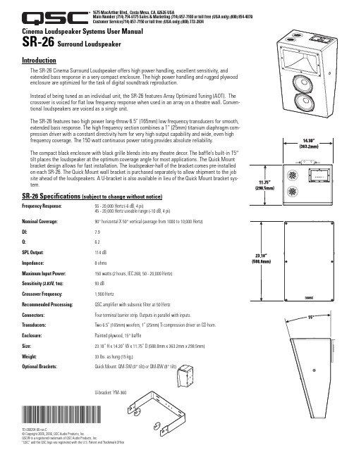
Cinema Loudspeaker Systems User Manual SR-26 Surround Loudspeaker IntroductionThe SR-26 Cinema Surround Loudspeaker offers high power handling, excellent sensitivity, andextended bass response in a very compact enclosure. The high power handling and rugged plywoodenclosure are optimized for the task of digital soundtrack reproduction.Instead of being tuned as an individual unit, the SR-26 features Array Optimized Tuning (AOT). Thecrossover is voiced for flat low frequency response when used in an array on a theatre wall. Conven-tional loudspeakers are voiced as a single unit.The SR-26 features two high power long-throw 6.5” (165mm) low frequency transducers for smooth,extended bass response. The high frequency section combines a 1” (25mm) titanium diaphragm com-pression driver with a constant directivity horn for very high output capability and wide, even highfrequency coverage. The 150 watt continuous power rating provides absolute reliability.The compact black enclosure with black grille blends into any theatre decor. The baffle’s built-in 15°tilt places the loudspeaker at the optimum coverage angle for most applications. The Quick Mountbracket design allows for fast installation. The loudspeaker-half of the bracket comes pre-installedon each SR-26. The Quick Mount wall bracket is purchased separately to allow shipment to the jobsite ahead of the loudspeakers. A U-bracket is also available in lieu of the Quick Mount bracket sys-tem.SR-26 Specifications (subject to change without notice)Frequency Response:55 - 20,000 Hertz (-6 dB, 4 pi)45 - 20,000 Hertz useable range (-10 dB, 4 pi)Nominal Coverage:90° horizontal X 50° vertical (average from 1000 to 10,000 Hertz)DI:7.9Q: 6.2SPL Output:114 dBImpedance: 8 ohmsMaximum Input Power:150 watts (2 hours, IEC 268, 50 - 20,000 Hertz)Sensitivity (2.83V, 1m): 93 dBCrossover Frequency:1,900 HertzRecommended Processing:QSC amplifier with subsonic filter at 50 HertzConnectors:Four terminal barrier strip. Outputs in parallel with inputs.Transducers:Two 6.5” (165mm) woofers, 1” (25mm) Ti compression driver on CD horn.Enclosure:Painted plywood, 15° baffleSize:23.18” H x 14.30” W x 11.75” D (588.8mm x 363.2mm x 298.5mm)Weight:33 lbs. as hung (15 kg.)Optional Brackets:*TD-000204-00*TD-000204-00 rev.C© Copyright 2005, 2006, QSC Audio Products, Inc.QSC® is a registered trademark of QSC Audio Products, Inc.“QSC” and the QSC logo are registered with the U.S. Patent and Trademark Office 1675 MacArthur Blvd., Costa Mesa, CA, 92626 USAMain Number (714) 754-6175 Sales & Marketing (714) 957-7100 or toll free (USA only) (800) 854-4079Customer Service(714) 957-7150 or toll free (USA only) (800) 772-2834ConnectionsThe SR-26 has barrier strip screw terminals that accept up to #10 AWG stranded loudspeaker wire.Input- Connect the amplifier’s output signal to the loudspeaker’s INPUT terminals. Observe proper polarity. Use the largest wire size and shortest length for the application.Output- The SR-26 has two terminals marked OUTPUT. These terminals are connected in parallel to the INPUT terminals and can be used for con-necting multiple SR-26 enclosures in parallel with one another. Connect the OUTPUT terminals to the next loudspeaker’s INPUT terminals. Observe proper polarity of connections.Warnings and Important NotesNOTE! Maintain proper loudspeaker connection polarity throughout the entire system for maximum performance.NOTE! Ensure that the amplifier driving the parallel loudspeakers is rated to drive the lower impedance (Example: 4 enclo-sures in parallel will yield 2 ohms impedance, nominally).Use QSC’s Quick Mount bracket or U-bracket for wall mounting. Enclosure is not designed to be suspended, flown, orrigged by any other method. Do not suspend, fly, or rig this enclosure.Always keep sound pressure levels in the listening area below levels that can damage human hearing.Install in accordance with QSC Audio Product’s instructions and a licensed, professional engineer. Only use attachments, mounts, accessories, or brackets specified by QSC Audio Products, Inc. Refer all servicing to qualified personnel. Servicing is required when the apparatus has been damaged in any way.WARNING! Before placing, installing, rigging, or suspending any speaker product, inspect all hardware, suspension, cabi-nets, transducers, brackets and associated equipment for damage. Any missing, corroded, deformed or non-load rated com-ponent could significantly reduce the strength of the installation, placement, or array. Any such condition severely reduces the safety of the installation and should be immediately corrected. Use only hardware which is rated for the loading condi-tions of the installation and any possible short-term unexpected overloading. Never exceed the rating of the hardware or equipment. Consult a licensed, professional engineer when any doubt or questions arise regarding a physical equipment installation.Warranty (USA only; other countries, see your dealer or distributor)DisclaimerQSC Audio Products, Inc. is not liable for any damage to amplifiers, or any other equipment that is caused by negligence or improper installation and/or use of this loudspeaker product.QSC Audio Products 3 Year Limited WarrantyQSC Audio Products, Inc. (“QSC”) guarantees its products to be free from defective material and / or workmanship for a period of three (3) years from date of sale, and will replace defective parts and repair malfunctioning products under this warranty when the defect occurs under normal installation and use - provided the unit is returned to our factory or one of our authorized service stations via pre-paid transportation with a copy of proof of purchase (i.e., sales receipt).This warranty provides that the examination of the return product must indicate, in our judgment, a manufac-turing defect.This warranty does not extend to any product which has been subjected to misuse, neglect, accident, improper installation, or where the date code has been removed or defaced. QSC shall not be liable for incidental and/or consequential damages.This warranty gives you specific legal rights. This limited warranty is freely transferable during the term of the warranty period.Customer may have additional rights, which vary from state to state.In the event that this product was manufactured for export and sale outside of the United States or its territories, then this limited warranty shall not apply. Removal of the serial number on this product, or purchase of this product from an unauthorized dealer, will void this limited warranty.Periodically, this warranty is updated. To obtain the most recent version of QSC’s warranty statement, please visit . Contact us at 800-854-4079 or visit our website at .Manual del usuario de los sistemas de altavoces para salas de cine Altavoz envolvente SR-26IntroducciónEl altavoz SR-26 de sonido envolvente para salas de cine ofrece un manejo superior de la potencia, exce-lente sensibilidad y respuesta extendida a los bajos en una caja muy compacta. El manejo superior de la potencia y la resistente caja de madera contrachapada están optimizados para la tarea de la reproducción digital de la pista de sonido.En lugar de estar afinado como una unidad individual, el altavoz SR-26 ofrece la configuración de afi-nación óptima (Array Optimized Tuning, AOT). El cruce está ajustado para una respuesta de baja frecuen-cia plana cuando se usa en la configuración de una pared de teatro. Los altavoces convencionales están ajustados como unidades sencillas.El altavoz SR-26 tiene dos transductores de baja frecuencia de alta potencia y largo alcance de 6.5” (165 mm) para dar una respuesta extendida uniforme a los bajos. La sección de alta frecuencia combina un excitador de compresión de diafragma de titanio de 1” (25 mm) con un cuerno de directividad constante para una capacidad de salida muy alta y una cobertura de frecuencia alta, ancha y uniforme. La capacidad nominal de potencia continua de 150 watts proporciona una fiabilidad absoluta.La compacta caja negra con rejilla negra se adapta a la decoración de cualquier teatro. El dispositivo de inclinación de 15° integrado en la pantalla acústica coloca el altavoz en el óptimo ángulo de cobertura para la mayoría de las aplicaciones. El diseño del soporte Quick Mount permite una instalación rápida. La mitad del soporte del altavoz viene instalado en cada altavoz SR-26. El soporte Quick Mount de montaje en la pared se compra por separado para permitir su entrega en el lugar de trabajo antes de la entrega de los altavoces. También hay disponible un soporte en U en lugar del sistema de soporte Quick Mount.Especificaciones del sistema SR-26 (sujetas a cambio sin previo aviso)Respuesta de frecuencia:55 - 20,000 hertzios (-6 dB, 4 pi)Intervalo utilizable de 45 - 20,000 hertzios (-10 dB, 4 pi)Cobertura nominal:90° horizontal X 50° vertical (promedio de de 1000 a 10,000 hertzios)DI:7.9Q: 6.2SPL máxima:114 dBImpedancia: 8 ohmiosPotencia máxima de entrada :150 watts (2 hours, IEC 268, 50 - 20,000 hertzios)Sensibilidad (2.83V, 1m): 93 dBFrecuencia de cruce:1,900 hertziosProcesamiento recomendado:Amplificador QSC con filtro subsónico a 50 hertziosConectadores:Tira de barrera de cuatro terminales. Salidas en paralelo con las entradas.Transductores:Dos woofers de 6.5” (165 mm), un excitador de compresión de titanio de 1” (25 mm) en un cuerno CD.Caja:Madera contrachapada pintada, pantalla acústica de 15°Tamaño:23.18” de alto X 14.30” de ancho X 11.75” de profundidad (588.8 mm X 363.2 mm X 298.5 mm)Peso:33 libras colgado (15 kg.)Soportes opcionales:Quick Mount: QM-SW (inclinación de 0°) o QM-BW (inclinación de 8°)Soporte en U: YM-3601675 MacArthur Blvd., Costa Mesa, CA, 92626 EE.UU.Número principal (714) 754-6175 Ventas y Comercialización (714) 957-7100 o línea sin costo (sólo para EE.UU.) (800) 854-4079Servicio al cliente(714) 957-7150 o línea sin costo (sólo en EE.UU.) (800) 772-2834ConexionesEl SR-26 tiene terminales de tornillo de barra protectora que aceptan alambre trenzado de calibre de hasta #10 AWG para altavoces.Entrada- Conecte la señal de salida del amplificador en los terminales de ENTRADA del altavoz. Observe la polaridad adecuada. Use el alambre de calibre más grande y de longitud más corta para la aplicación.Salida- El altavoz SR-26 tiene dos terminales marcados como SALIDA. Estos terminales están conectados en paralelo a los terminales de ENTRADA y se pueden usar para conectar en paralelo entre sí múltiples cajas del altavoz SR-26. Conecte los terminales de SALIDA en los terminales de ENTRADA del siguiente altavoz. Observe la polaridad adecuada de las conexiones.Advertencias y notas importantes¡NOTA! Mantenga la polaridad adecuada en la conexión del altavoz en todo el sistema para obtener el máximorendimiento.¡NOTA! Asegúrese de que el amplificador que acciona los altavoces en paralelo esté clasificado para accionar la menor impedancia (por ejemplo: 4 cajas en paralelo producirán una impedancia nominal de 2 ohmios).Use el soporte Quick Mount de QSC o el soporte en U para montaje en la pared. La caja no está diseñada para sersuspendida, montada en voladizo, sobre arneses o por ningún otro método. No suspenda esta caja, no la monte en voladizo ni sobre arneses.Siempre mantenga los niveles de presión del sonido en un área de audición con un nivel menor que el que provoca daños al oído humano.Instale de acuerdo con las instrucciones de QSC Audio Products y de un ingeniero profesional con la debida licencia. Sólo use piezas, montajes, accesorios y soportes especificados por QSC Audio Products, Inc. Refiera todo el servicio a personal calificado. Cuando el aparato haya sido dañado de alguna manera, es necesario proporcionarle servicio.¡ADVERTENCIA! Antes de colocar, instalar, montar o suspender cualquier producto de altavoz, inspeccione todo el pro-ducto, la suspensión, las cajas, los transductores, los soportes y el equipo asociado para detectar la existencia de daños.Cualquier componente faltante, corroído, deformado, o sin carga nominal podría reducir significativamente la resistencia de la instalación, la colocación o la configuración. Cualquier condición de este tipo reduce gravemente la seguridad de la instalación y debe corregirse de inmediato. Use sólo herraje que esté clasificado para las condiciones de carga de lainstalación y cualquier carga excesiva deberá ser en el menor corto plazo posible Nunca exceda el valor nominal delequipo físico ni del dispositivo. Consulte a un ingeniero profesional con la debida licencia cuando surjan dudas o pregun-tas referentes a la instalación física del equipo.Garantía (sólo para EE.UU.; para otros países, consulte con su vendedor o distribuidor)RenunciaQSC Audio Products, Inc. no es responsable por ningún daño a los amplificadores, ni a ningún otro equipo que sea causado por negligencia o instalación y/o uso inadecuado de este altavoz.Garantía limitada de 3 años de QSC Audio ProductsQSC Audio Products, Inc. (“QSC”) garantiza que sus productos estarán libres de materiales y/o mano de obra defectuosos por un periodo de tres (3) años a partir de la fecha de la venta, y reemplazará las piezas defectuosas y reparará los productos que funcionen mal bajo esta garantía cuando el defecto ocurra bajo condiciones normales de instalación y uso, siempre y cuando la unidad se devuelva a nuestra fábrica o a una de nuestras estaciones autorizadas de servicio mediante transportación prepagada con una copia del comprobante de compra (por ejemplo, el recibo de la compra).Esta garantía requiere que el examen del producto devuelto indique, en nuestra opinión, un defecto de fabricación.Esta garantía no se extiende a ningún producto que hubiera estado sometido a uso indebido, negligencia, accidente, instalación incorrecta, o en el que se hubiera quitado o modificado el código de la fecha.QSC tampoco será responsable por daños incidentales y/o emergentes.Esta garantía le otorga derechos legales específicos. Esta garantía limitada es libremente transferible durante el período de la misma.El cliente podría gozar de derechos adicionales, que podrían variar de un estado a otro.En caso de que este producto fuera fabricado para exportación y venta fuera de los Estados Unidos o sus territorios, entonces no será aplicable esta garantía limitada. La eliminación del número de serie en este producto, o la compra de este producto, de un distribuidor no autorizado, anulará esta garantía limitada. Esta garantía se actualiza periódicamente. Para obtener la versión más reciente de la declaración de garantía de QSC, visite . Comuníquese con nosotros en 800-854-4079 o visite nuestro sitio en Internet en .Manuel d’utilisation de systèmes de haut-parleurs de cinémaHaut-parleur d’ambiance SR-26IntroductionLe haut-parleur d’ambiance cinéma SR-26 est synonyme de grande puissance, d’excellente sensibilité et de réponse aux graves étendue dans une enceinte ultra-compacte. L’enceinte en contreplaqué solide et compatible avec une haute puissance est optimisée pour la reproduction de pistes-son numériques.Au lieu d’être réglé comme un appareil individuel, le SR-26 a une fonction globale de réglage optimisé (AOT). Le filtre passif est réglé pour une réponse basse fréquence uniforme lorsqu’il est utilisé dans une série, sur le mur d’une salle de cinéma. Les haut-parleurs conventionnels sont réglés indépendamment.Le SR-26 a deux transducteurs basse fréquence de 165mm longue portée et ultra-puissants pourproduire une réponse aux graves étendue et lisse. La section haute fréquence associe un étage d’attaque de compression à membrane de 25mm en titane à un pavillon acoustique à directivitéconstante pour une très haute puissance en sortie et une large couverture haute fréquence uniforme. La puissance nominale continue de 150 watts est un gage de fiabilité absolue.L’enceinte noire compacte à grille noire se fond dans tout décor de salle de cinéma. L’inclinaison à 15° intégrée positionne le haut-parleur à un angle optimal de couverture pour la plupart des applications. Le support Quick Mount permet une installation rapide. La moitié «haut-parleur » du support est livréepré-installée sur chaque SR-26. Le support Quick Mount s’achète séparément pour permettre une arrivée sur site avant les haut-parleurs. Un support en U est également disponible à la place du système de supports Quick Mount.Caractéristiques techniques du SR-26 (sujettes à modification sans préavis)Réponse en fréquence :55 à 20000 Hz (-6 dB, 4 pi)45 à 20000 Hz (plage utile) (-10 dB, 4 pi)Couverture nominale :90° horizontal x 50° vertical (moyenne de 1 000 à 10000 Hz)Indice de directivité:7,9Q :6,2SPL maximum :114 dBImpédance : 8 ohmsPuissance d’entrée maximum :150 watts (2 hours, IEC 268, 50 - 20 000 Hz)Sensibilité (2,83 V, 1 m): 93 dBFréquence du filtre passif :1900HzTraitement recommandé:Amplificateur QSC avec filtre subsonique à 50HzConnecteurs :Bornier à cloisons quatre bornes. Sortie en parallèle aux entrées.Transducteurs :Haut-parleur de graves de 165mm, étage d’attaque de compression en titane de25mm sur le pavillon acoustique CD.Enceinte :Contreplaqué peint, 15° d’inclinaisonDimensions :588,8mm (H) x 363,2mm (l) x 298,5mm (P)Poids :15kg à l’état suspenduSupports en option :Quick Mount : QM-SW (0° d’inclinaison) ou QM-BW (8° d’inclinaison)Support en U : YM-3601675 MacArthur Blvd., Costa Mesa, CA 92626Téléphone (standard) (714) 754-6175 Ventes et Marketing (714) 957-7100 ou (800) 854-4079 (numéro vert valable aux États-Unis seulement)Service clientèle(714) 957-7150 ou numéro vert (États-Unis seulement) (800) 772-2834BranchementsLe SR-26 a des bornes vissables de bornier à cloisons qui acceptent des conducteurs de haut-parleurs toronnés pouvant atteindre #10 AWG.Entrée - Connecter le signal de sortie de l’amplificateur aux bornes INPUT du haut-parleur. Respecter la polarité indiquée. Utiliser des conducteurs de calibre maximal et de longueur minimale pour l’application.Sortie - Le SR-26 possède également deux bornes marquées OUTPUT (sortie). Ces bornes sont branchées en parallèles sur les bornes INPUT et peuvent être utilisées pour le branchement de plusieurs enceintes SR-26 en parallèle les unes aux autres. Connecter les bornes OUTPUT aux bornes INPUT du haut-parleur. Respecter la polarité correcte des branchements.Avertissements et remarques importantesREMARQUE! Pour une performance maximum, maintenir la polarité de branchement correcte à travers l’ensemble dusystème.REMARQUE! S’assurer que l’amplificateur qui pilote les haut-parleurs en parallèle est prévu pour un pilotage à basseimpédance (exemple: 4 enceintes en parallèle produiront une impédance nominale de 2 ohms).Utilisez le support Quick Mount de QSC ou le support en U pour une fixation murale. L’enceinte n’a pas été conçue pour être suspendue, balancée ou montée par une autre méthode. La suspension, le balancement ou le montage de l’enceinte sont interdits.Toujours maintenir les niveaux de pression sonore dans la zone d’écoute en deçà de niveaux susceptibles de compromettre l’ouïe.Installer conformément aux instructions de QSC Audio Products et d’un technicien professionnel diplômé. Utiliseruniquement des fixations, supports, accessoires ou équerres spécifiés par QSC Audio Products. Confier toutes lesréparations à un personnel qualifié. Une réparation ou maintenance est requise lorsque l’appareil a été endommagé d’une manière quelconque.AVERTISSEMENT! Avant de placer, installer, monter ou suspendre un haut-parleur, inspecter l’état de toute la visserie, du matériel de suspension, des armoires, des transducteurs, des supports et du matériel associé. Tout composant manquant, corrodé, déformé ou non adapté à la charge risque de réduire sensiblement la solidité de l’installation, sa mise en place ou sa portée. Une telle condition réduit sensiblement la sécurité de l’installation et doit être immédiatement corrigée. Utiliser uniquement du matériel de montage prévu pour les conditions de charge de l’installation et toute surcharge éventuelle à court terme imprévue. Ne jamais dépasser les spécifications nominales du matériel de montage ou de l’équipement.Consulter un technicien professionnel diplômé en cas de doute ou de question concernant l’installation physique del’équipement.Garantie (États-Unis seulement; dans les autres pays, consulter le revendeur ou le distributeur) Avis de non-responsabilitéQSC Audio Products, Inc. n’est pas responsable des dommages subis par les amplificateurs ou tout autre équipement causé par un acte de négligence ou une installation impropre et/ou l’utilisation de ce haut-parleur.QSC Audio Products - Garantie limitée de 3 ansQSC Audio Products, Inc. («QSC») garantit que ses produits sont dépourvus de tout vice de fabrication et /ou de matériel pendant une période de trois (3) ans à partir de la date de vente et remplacera les pièces défectueuses et réparera les produits qui fonctionnent mal dans le cadre de cette garantie si le défaut survient dans des conditions normales d’installation et d’utilisation - à condition que l’appareil soit retourné à l’usine ou à l’un de nos centres de réparation agréés en port prépayé, accompagné d’un justificatif d’achat (facture, par ex.).Cette garantie prévoit que l’examen du produit retourné doit indiquer, selon notre jugement, un défaut de fabrication.Cette garantie ne s’étend à aucun produit qui a été soumis à une utilisation abusive, un acte de négligence, un accident, une installation incorrecte ou un produit dont le code-date a été retiré ou effacé. QSC ne pourra être tenue pour responsable de dommages accessoires et/ou indirects.Cette garantie vous accorde des droits spécifiques. Cette garantie limitée est librement cessible durant sa période de validité.Le client pourra bénéficier d’autres droits, variables d’une juridiction à l’autre.Si ce produit a été fabriqué pour une exportation et une vente en dehors des États-Unis ou de ses territoires, cette garantie limitée ne s’appliquera pas. Le retrait du numéro de série sur ce produit ou l’achat de ce produit auprès d’un revendeur non agréé annulera cette garantie limitée. Cette garantie est régulièrement mise à jour. Pour obtenir la toute dernière version de la garantie de QSC, rendez-vous sur le site . Contactez-nous au 800-854-4079 ou visitez notre site Web .Kinolautsprecheranlagen - BenutzerhandbuchSurround-Lautsprecher SR-26 EinführungDer Kino-Surround-Lautsprecher SR-26 bietet hohe Belastbarkeit, hervorragende Empfindlichkeit und erweiterten Bass-Frequenzgang in einem besonders kompakten Gehäuse. Belastbarkeit und (aus robusten Sperrholzplatten mittlerer Dichte gefertigtes) Gehäuse sind für die digitale Tonspur-Wiedergabe optimiert.Anstelle einer individuellen Abstimmung kommt beim SR-26 die Array-optimierte Abstimmung (AOT) zur Anwendung. Beim Einsatz in einem Kinowand-Array ist die Frequenzweiche für den flachen NF-Frequenzgang ausgelegt. Konventionelle Lautsprecher sind als Einzelgeräte ausgelegt.Zur Erzielung eines glatten, erweiterten Bass-Frequenzgangs ist der SR-26 mit zwei leistungsfähigen 6,5 Zoll (165 mm) großen Long-Throw-Niederfrequenzwandlern ausgestattet. Ein 1-Zoll- (25 mm-) Titan-Komprimierungstreiber und ein Constant-Directivity-Horn im Hochfrequenz-Abschnitt gewährleisten eine besonders hohe Ausgangsleistung und eine breite, gleichmäßige Hochfrequenz-Abstrahlung. Dank einer kontinuierlichen Nennleistung von 150 W wird absolute Zuverlässigkeit erreicht.Das kompakte schwarze Gehäuse mit schwarzem Gitter passt sich jedem Kinodekor an. Durch die um 15° geneigte Anordnung der Schallwand wird ein für die meisten Anwendungen optimaler Abstrahlwinkel erzielt. Die Schnellmontage-Halterung ermöglicht ein schnelles Installieren. Die für den Lautsprecher vorgesehene Hälfte der Halterung ist auf dem SR-26 vormontiert. Da die Schnellmontage-Wandhalterung separat bestellt wird, kann sie bereits vor den Lautsprechern an den Einsatzort geliefert werden. Anstelle des Schnellmontage-Halterungssystems kann auch eine U-Profil-Halte-rung bestellt werden.SR-26 - Technische Daten (können jederzeit ohne vorherige Mitteilung geändert werden)Frequenzgang:55 - 20.000 Hz (-6 dB, 4 pi)Nutzbereich 45 - 20.000 Hz (-10 dB, 4 pi)Nominelle Abstrahlung:90° horizontal x 50° vertikal (durchschnittl. 1000 - 10.000 Hz)DI:7,9Q:6,2SPL Ausgang:114 dBImpedanz: 8 OhmMaximale Eingangsleistung:150 W (2 stunden, IEC 268, 50 - 20.000 Hz)Empfindlichkeit (2,83 V, 1 m): 93 dBCrossover-Frequenz:1900 HzEmpfohlene Verarbeitung:QSC-Verstärker mit Untertonfrequenzfilter bei 50 HertzSteckverbinder:Barrier-Strip mit vier Schraubklemmen. Die Ausgänge sind mit den Eingängen parallel geschaltet.Wandler Zwei 6,5-Zoll- (165-mm-) Woofer, 1-Zoll- (25-mm-) Ti-Komprimierungstreiber auf CD-Horn.Gehäuse:Lackiertes Sperrholz, 15°-SchallwandGröße:588,8 mm H x 363,2 mm B x 298,5 mm TGewicht:15 kgOptionale Halterungen:Schnellmontage QM-SW (0°-Neigung) oder QM-BW (8°-Neigung)U-Profil: YM-3601675 MacArthur Blvd., Costa Mesa, CA, 92626 USAZentrale +1 (714) 754-6175 Verkauf und Marketing (714) 957-7100 oder gebührenfrei (nur in den USA) (800) 854-4079Kundendienst+1 (714) 957-7150 oder gebührenfrei (nur in den USA) +1 (800) 772-2834VerbindungenDer SR-26 ist mit Barrier-Strip-Schraubklemmen für Lautsprecher-Litzendraht mit einem maximalen Querschnitt von 10 AWG (5,2 mm2) ausgestattet.Eingang - Das Verstärker-Ausgangssignal an die Lautsprechereingangsklemmen INPUT anschließen. Auf die korrekte Polarität achten. Stets den größt-möglichen Leiterquerschnitt und die kürzeste Leiterlänge verwenden.Ausgang - Der SR-26 ist ferner mit zwei Ausgangsklemmen (OUTPUT) ausgestattet. Diese Klemmen sind parallel mit den Eingangsklemmen (INPUT) ver-bunden und dienen der parallelen Verbindung mehrerer SR-26-Gehäuse. Bei dieser Konfiguration werden die Ausgangsklemmen (OUTPUT) mit den Einga-ngsklemmen (INPUT) des nächsten Lautsprechers verbunden. Bei der Herstellung der Anschlüsse darauf achten, dass die richtige Polarität gewahrt ist.Achtungshinweise und andere wichtige HinweiseHINWEIS! Zur Optimierung der Leistung muss die richtige Polarität der Lautsprecheranschlüsse in der gesamten Anlage gewahrt sein.HINWEIS! Achten Sie darauf, dass die parallel geschalteten Lautsprecher von einem Verstärker getrieben werden, dessen Nennwert der niedrigeren Impedanz entspricht (Beispiel: 4 parallel geschaltete Gehäuse ergeben eine Impedanz vonnominell 2 Ohm).Die QSC-Schnellmontage-Halterung bzw. das U-Profil eignet sich für die Befestigung an der Wand. Das Gehäuse ist nicht für Hänge-, Flug- oder sonstige Rigging-Anwendungen vorgesehen. Dieses Gehäuse darf weder aufgehängt noch in Flug- oder Rigging-Anwendungen eingesetzt werden.Den Schalldruckpegel stets auf einen Pegel im Hörbereich einstellen, der keinen Gehörschaden verursacht.Die Installation von einem lizenzierten Fachtechniker gemäß der Anleitung von QSC Audio Products vornehmen lassen. Nur von QSC Audio Products, Inc. spezifizierte Befestigungskomponenten, Montagezubehör oder Halterungen verwenden. War-tungsarbeiten nur von qualifiziertem Personal ausführen lassen. Wartungsmaßnahmen sind erforderlich, wenn das Produkt auf irgendeine Weise beschädigt wurde.ACHTUNG! Inspizieren Sie vor dem Aufstellen, Installieren, Rigging oder Aufhängen von Lautsprecherprodukten alle Befes-tigungsteile, Aufhängungen, Gehäuse, Wandler, Halterungen und damit in Verbindung stehende Vorrichtungen auf eventu-elle Schäden. Fehlende, korrodierte, verformte oder nicht belastbare Komponenten könnten die Stabilität der Installation, der Aufstellung oder der Gerätekombination deutlich reduzieren. Jeder Zustand dieser Art bewirkt eine erhebliche Verrin-gerung der Sicherheit der Installation und sollte umgehend behoben werden. Verwenden Sie ausschließlich Befes-tigungsteile, die für die Belastungsbedingungen der Installation zugelassen und für jede potenzielle, unerwartete, kurzfris-tige Überlastung ausgelegt sind. Die Nennleistung der Befestigungsteile bzw. Ausrüstung darf keinesfalls überschritten werden. In Zweifelsfällen oder bei Fragen zur Installation eines Geräts sollten Sie einen qualifizierten Techniker hinzuziehen.Garantie (nur für die USA; wenden Sie sich zwecks Garantieinformationen für andere Länder an Ihren Händler oder Distributor)HaftungsausschlussQSC Audio Products, Inc. ist nicht für Schäden an Verstärkern oder anderen Geräten haftbar, die durch Fahrlässigkeit oder eine unsachgemäße Installation und/ oder Verwendung dieses Lautsprecherprodukts verursacht werden.Beschränkte Dreijahresgarantie durch QSC Audio ProductsQSC Audio Products, Inc. (…QSC“) gewährleistet, dass seine Produkte für einen Zeitraum von drei (3) Jahren ab dem Kaufdatum keine Material- und/oder Aus-führungsfehler aufweisen werden, und QSC verpflichtet sich zum Ersatz defekter Teile und zur Reparatur funktionsgestörter Produkte gemäß dieser Garantie, wenn dieser Fehler bei einer normalen Installation und unter normalen Gebrauchsbedingungen auftritt – vorausgesetzt, dass das Gerät unter Vorauszahlung der Trans-portkosten und zusammen mit einer Kopie des Kaufnachweises (z.B. der Kaufquittung) an unser Werk zurückgeschickt oder an eine unserer autorisierten Kundendienststellen eingeschickt wird.Diese Garantie setzt voraus, dass die Prüfung des zurückgeschickten Produkts in unserem Ermessen einen Herstellungs defekt zu erkennen gibt.Diese Garantie erstreckt sich auf keine Produkte, die einer unsachgemäßen oder fahrlässigen Behandlung, Unfällen oder einer unvorschriftsmäßigen Installation unterlagen, oder deren Datumscode entfernt oder unkenntlich gemacht wurde. QSC ist für keine Neben- und/oder Folgeschäden haftbar.Diese Garantie gewährt Ihnen bestimmte Rechte. Diese beschränkte Garantie ist während der Garantiezeit frei übertragbar.Manche Kunden können je nach Rechtsprechung zusätzliche und andere Rechte besitzen.Falls dieses Produkt zum Export und Verkauf außerhalb der Vereinigten Staaten oder deren Hoheitsgebieten hergestellt wurde, besitzt diese eingeschränkte Garantie keine Gültigkeit. Die Entfernung der Seriennummer auf diesem Produkt oder der Kauf dieses Produkts von einem nicht autorisierten Händler macht diese beschränkte Garantie unwirksam. Diese Garantie wird gelegentlich aktualisiert. Die jeweils aktuellste Version der Garantieerklärung von QSC finden Sie im Internet unter . Sie erreichen uns telefonisch unter +1 800-854-4079 (gebührenfrei in den USA und Kanada) oder im Internet unter.。
克利普拉德10mm小型 valued的产品说明说明书
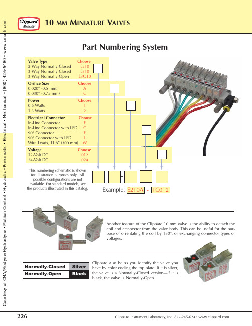
Part Numbering SystemAnother feature of the Clippard 10 mm valve is the ability to detach the coil and connector from the valve body. This can be useful for the pur-pose of orientating the coil by 180°, or exchanging connector types or voltages.Clippard also helps you identify the valve you have by color coding the top plate. If it is silver,the valve is a Normally-Closed version—if it is black, the valve is Normally-Open.the products illustrated in this catalog.C o u r t e s y o f C M A /F l o d y n e /H y d r a d y n e ▪ M o t i o n C o n t r o l ▪ H y d r a u l i c ▪ P n e u m a t i c ▪ E l e c t r i c a l ▪ M e c h a n i c a l ▪ (800) 426-5480 ▪ w w w .c mOne-piece gasket for manifold mountHIGHLY VISIBLE manual override provides valve actuation without powerHigh durability and corrosion-resistant glass filled nylon housingLED for confirmation of operationMultiple connectors - Snap-in Plugs - Wire Leads - Custom PlugsMounting Screws:M1.7 x 0.35Front left corner of valve!FKM seals and Buna N gasket (FKM available)2- or 3-ported valves in Normally-Closed and Normally-OpenDiodes for current spike suppression and a power saving circuit is availableEnclosed low wattage coils. Available in 12VDC or 24 VDC. Special voltages available forOEMs.Functional SchematicsNormally-Closed Normally-Closed Normally-Open 2-Way Valve3-Way Valve3-Way ValveAt Rest Actuated At Rest Actuated At Rest Actuatedsupplyoutputexhaust S - Supply E - Exhaust O - OutputS OS OS E O S E OE S OE S OC o u r t e s y o f C M A /F l o d y n e /H y d r a d y n e ▪ M o t i o n C o n t r o l ▪ H y d r a u l i c ▪ P n e u m a t i c ▪ E l e c t r i c a l ▪ M e c h a n i c a l ▪ (800) 426-5480 ▪ w w w .c mt e s t e dt oo v e r100 m i l l i o nc y c l e s !Medium: Air, Gas or other Compatible FluidsWorking Pressure: Vacuum to 110 psig/7.6 bar max.See Chart belowMax. Flow Rate: Standard: 0.5 scfm (14 l/min);High Flow: 0.8 scfm (23 l/min)Exhaust Flow: 0.8 scfm (23 l/min)Response Time: 8 ms when energized; 10milliseconds when de-energized*Add Voltage Choice to the end of each Base Part Number. Example: E210A-1C012SpecificationsElectrical: 12 VDC or 24 VDCPower Consumption: 0.5 or 1.3 watts dependent on orifice size and pressure Material: Stainless steel core and springs, springs, nylon body, FKM seals, and Buna-N gasket. FKM gasket available, consult factory Temperature Range: 23 to 122°F (-5 to 50°C)C o u r t e s y o f C M A /F l o d y n e /H y d r a d y n e ▪ M o t i o n C o n t r o l ▪ H y d r a u l i c ▪ P n e u m a t i c ▪ E l e c t r i c a l ▪ M e c h a n i c a l ▪ (800) 426-5480 ▪ w w w .c m aIn-Line ConnectorElectrical Specificationsw .c mConnectorsWire Connector must be ordered separately. ManifoldsManifolds are available for one to 12 valves, and are supplied with mount-ing screws and gaskets. Spare hardware and closing plates also available.Add -M5 for Metric ports.Order No. C2A-RB300 Connector with Cable, 11.8” (300 mm)C2A-RB500Connector with Cable, 19.69” (500 mm)C2A-RB1000Connector with Cable, 39.37” (1,000 mm)Molex connector #050013-80000.Cover PlateManifold Cover Plate includes plate, gasket and two screws.Order No. E10M-CP 10 mm Cover Plate(12.8)(10.0)M1.7 x Multi-Station ManifoldsOrder No. E10M-01Single Station ManifoldBy selecting the appropriate connector type for your 10 mm valve, tight spaces, orientation issues and electrical requirements can be accommodated easily.10- to 16-Station Manifoldsn C o n t r o l ▪ H y d r a u l i c ▪ P n e u m a t i c ▪ E l e c t r i c a l ▪ M e c h a n i c a l ▪ (800) 426-5480 ▪ w w w .c m。
PLA 85 说明书
50119511 G1 Valid from 2018 week 46PLA 85Pos. No. Varebetegnelse Description of goods WarenbezeichnungDésignation des pièces80690085 Plasmaslange med centraltilslutning, 6m Plasma torch with central adaptor plug, 6m Plasmaschlauch mit Zentralanschluss, 6m Torche plasma avec raccordement central, 6m 1 45050101 TastTrigger Taster Gâchette 2 71610194 Monteret print PCBPlatine Circuit imprimé montée 3 80600096 VippearmTipping device Kippvorrichtung Dispositif à bascule 4 80600092 Håndtag Handle HandgriffPoignée5 80600098 Skruer for håndtag (1 sæt = 5 stk)Screw for handle (1 set = 5 pcs) Schraube für Handgriff (1 Satz = 5 Stück) Vis pour poignée (1 jeu = 5 pièces) 6 80600097 Kontaktstift Contact pin Kontaktstift Fiche de contact 7 80650005 Brænderhoved Torch body Brennerkörper Corps de torche 7a 80600018 Gasrør Gas tube Gasrohr Tubeà gaz 8 80610005 Elektrode Electrode Elektrode Electrode9 80630009 Dyse 1,2 mm Nozzle 1.2 mm Düse 1,2 mm Buse 1,2 mm 9 80630010 Dyse 1,4 mm Nozzle 1.4 mm Düse 1,4 mmBuse 1,4 mm 10 80630011 Beskyttelseskappe Protective capSchutzkappe Bague de protection 11 80600088 Afstandsfjeder Distance spring AbstandsfederRessort de distance 12 80600101 Afstandsbøjle (2 ben)Distance ring (2 legs)Distanzbügel (2 Schenkel) Dispositif de distance (2 pied)12A 80600108 Afstandsbøjle Distance ringDistanzbügel Dispositif de distance 13 24510237 NøgleKey Universalschlüssel Clef14 82034014 GasflowmeterGas flowmeter GasdurchflußmesserDébitmètre de gaz15 80680085 Slangemodul PDX 85 m/ZA, 6mHose module PDX 85 with ZA, 6mSchlauchmodul PDX 85 with ZA, 6m Module de torche PDX 85 avec ZA, 6m 16 45070007 Slangeaflastning ø35 Hose protection ø35Schlauchentlastung ø35 Douille isolate de cable ø3517 40110406 CHJ skrue M4x6CHJ screw M4x6 Zylinderkopfschraube M4x6 Vis CHJ screw M4x618 25450047 Aflastningsring Relief-ringEntlastungsringBague d’allègement 19 80200335 Møtrik til ZA, plastik Nut for ZA, plasticMutter für ZA, Plastik Écrou pour ZA, plastique 20 80300601 Centraltilslutning Central adaptor plug ZentralsteckerFiche de contact 21 80300603 Hanstik kontaktdel Male contact partKontaktteil männlich Partie de contact, mâle 21a 80300602 Hanstik til ledningMale pin for wireKontaktteil für Leitung, männlich Connecteur mâle (câble)22 80600091 Cirkelslag kompletCircle cutting device completeKreisschneide-Einrichtung komplett Support pour coupe circulaire complet 22A 80600094 Stang for cirkelslagRadius arm for circle cutting device Führungsstang für Kreisschneide-Einrichtung Bras support pour coupe circulaire 22B 80600090 Brændervogn (drejebar) Torch carriage (revolving) Brennerwagen (drehbar) Support torche (pivotant)23 80600093 Brændervogn (fast) Torch carriage (fixed)Brennerwagen (fest)Support torche (fixe)。
联合上海鑫利晟电子有限公司产品说明书
UNDERCOUNTER DISHWASHER MODELS:KDPM704KPS0(Stainless)Illus.No.Part No.Description1Literature PartsW11323304Owners ManualW11404477Energy GuideW11366142Tech Sheet2Arm,HingeW10920232Left HandW10920230Right Hand3W11377160Cross Brace,Door 4W10273971Screw Illus.No.Part No.Description5Access PanelW11108979Black6Panel,Front(IncludesItem11)W11233313Stainless7W10858705Cover,Handle Pocket8W10919858Insulation,Multi-Layer9W11038694Insulation,SingleLayerIllus.No.Part No.Description10W10919859Insulation,Front Panel11W10692757Barrel Nut,Front Panel12W11170267Screw,Black13Toe PanelW11108991Black14W11364953Screw153400000ScrewIllus.No.Part No.Description1Console Assembly(Includes Insert)W11106346Black2W11084876Jumper,Door3W10889948Jumper,UI4W10711884Screw(Long)5W11091934Latch Assembly(Includes Switch) 6W11351659Control,Electronic7W11025634Bezel,Vent(Also Order Gasket)Illus.No.Part No.Description8W11184028Gasket,Vent9W10348409Screw10W11098822Inner Door Assembly11W11454757Seal,Door Bottom12W11330869Wiring Harness,Main(Includes Thermostat&Fuse)13W11084867Wiring Harness,InnerDoor14W11092649Dispenser Assembly15W11265187Seal,Console/DoorIllus.No.Part No.Description16W11088985Hanger,Control17W11038720Vent Assembly(Includes Fan)(Also Order Gasket)18W11038734Duct,Vent19W11258418Screw20W11397505Fuse,In-lineIllus.No.Part No.Description1W11120458Tub Assembly(includes gasket) 2W11226744Base,Terminal Box3W11035860Gasket,Tub4W11036127Nut,Water Inlet5W11090487Strike,Latch6W11296374Screw7W11165091Seal,Cabinet8W11025993Drip Tray9W11025986Funnel,OverfillProtection10W11025988Funnel Extension118269145Bracket,Undercounter 12W11165093Cover,Tub Corner Illus.No.Part No.Description13W11036170Float Switch14W11184083Plug,Tub15W11289893Water Inlet Assembly16W11455395Leg,Leveling173378128Washer,Pronged Cup183400014Screw,Grounding19W10277003Screw20W11226746Cover,Terminal Box21Side Support,TubW10920122Left HandW10920120Right Hand22W11221921Shiled,Tub Sound23W11132441Terminal BlockIllus.No.Part No.Description24W11362501Miscellaneous PartsBag(Contains2Screws,2Clamps,&2Brackets)25W11104729Nut,Heater Terminal26W11047695Heater ElementAssemblyIllus.No.Part No.Description1W11122133Pump Assembly2W11294352Isolator,Front Motor3W10891545Diffuser,Inlet4W11294350Hanger,Front Motor59741232Screw6W10891547Check Valve,Drain7W11048456Wash Arm Assembly8W11108699Filter Assembly9W10380239Ring,Volute10W11345228Motor&SumpAssembly11W11036663Isolator,Rear Motor 12W11250985Hose,Pressure Illus.No.Part No.Description13W10900387Hose,Suction14W11035709Motor,Drain15W11131184Hose,Drain16W10903468Disc,Diverter17W11025963Bracket,Rear Motor18W11418271Fastener19W11126174Indicator,OpticalWash20370445Clamp,Hose21W11163419Bracket,Thermostat22W11193089Thermostat(Includedwith Main WiringHarness)23W11025970Fill Valve AssemblyIllus.No.Part No.Description24W11122851Clamp,Hose25W11036161Hose26W11036143Clip,Hose27W10466656Clamp,Hose28W11036287Hose,Inlet29W11236576Clamp,Hose30W11039864Grate31371505Clamp,Hose32Diverter Valve Motor(Not Serviced)33W11034556Sump34W10753070CapacitorUPPER WASH AND RINSE PARTSUPPER WASH AND RINSE PARTSIllus.No.Part No.Description1W10872558Feed Tube Assembly2W11039888Retainer3W11039869Sprayarm,Third Level Illus.No.Part No.Description4W11174340Upper SprayarmAssembly5W10903465Cover,DiverterIllus.No.Part No.Description6W10892836Retainer,Docking(2nd Level)7W10892835Retainer,Docking(3rdLevel)Illus.No.Part No.Description1W10847876Dishrack,Upper2W11310287Clip,Stemware3W11180178Leveler,Adjuster Arm4W11180605Clip,Adjuster Arm5W11267699Button,Adjuster Arm6Adjustment AssemblyW11268082Left HandW11268078Right Hand Illus.No.Part No.Description7Track,AssemblyW11212732Left HandW11212734Right Hand8W11268682Handle,DishrackFront9W11268681Handle,Dishrack Rear109741232Screw11W11186528Tine Row,Fold Down12W11179753Clip,PivotIllus.No.Part No.Description13W11179755Positioner14W11170270ScrewIllus.No.Part No.Description1W11224324Dishrack,Lower2W11133746Wheel&TransportAssembly3W11291798Silverware BasketAssembly4W11267718Lid,Silverware Basket Illus.No.Part No.Description5W10056272Tine Row,Fold Down6W11268658Retainer,Flex Row7W10554952Tine Row,Sliding8W11268661Retainer,Sliding TineRowIllus.No.Part No.Description9W11392620Handle,DishrackFront10W11268681Handle,Dishrack Rear119741232Screw12W11267721Utensil BasketIllus.No.Part No.Description1W11127727Rack,Third Level2Track Assembly W11047813Left HandW11047815Right Hand3W11184071Hanger,Tube4W11130709Mount,Dishrack Illus.No.Part No.Description5W11392620Handle,DishrackFront6W11268681Handle,Dishrack Rear79741232Screw8W11202101Cup Guard9W11087823Silverware TrayIllus.No.Part No.Description10W10830577Bracket,Front Hanger11W10830523Drive Box Assembly,Manifold12W11101860Cover,Wash Tube13W10831864Tube,Wash14W10920244Nut,TubOPTIONAL PARTS(NOT INCLUDED) Illus.No.Part No.Description4396277Barrier KitW11381654External Drain Hose,12FTW11365011Power Cord Kit(Straight)W11365014Power Cord Kit(RightAngle)4396672Strain Relief,PowerCord(Metallic)W10685193Compression HoseFitting,Water LineW10278635RP..Fill Hose Kit。
Gasboy PLUS 系列产品介绍说明书
> Manage your operation from anywhere: the office, home or on the road.
> Customizable reports are easy to configure to your specific needs.
> Schedule proactive vehicle maintenance based on accurate and timely information.
sites with a single fuel island > Lighted terminals available 24/7/365 for
unattended sites > Supports multiple access technologies,
including web-based and contactless systems
ICR PLUS is Gasboy’s island card reader for use with CFN PLUS. It supports multiple access technologies, including web-based and contactless systems. > Lighted terminals available 24/7/365 for
stationary equipment from a tanker truck. It’s fully compatible with the other Gasboy PLUS series so that transaction information stored on the Fuel Truck Controller uploads into the Fleet Head Office when the tanker truck returns to the fuel island. > Extends your fleet management system to
Samtec QTH QSH系列连接器规格说明书
-NO. OF PAIRS-01-----OPTION-QMSHeaderQFSSocket–026, –052,–078–D = (52 total pins per bank)–016, –032,–048–D–DP = (16 pairsper bank)–SL= 10 µ" (0.25 µm) Gold on Signal Pins and Ground Plane, Matte Tin on tails–D = Single-Ended –D–DP= DifferentialPair–MG= Metal Guide Post (QMS only)–K= Polyimidefilm Pick & Place PadLeave blank for Tray Packaging –TR= Tape & Reel (–016, –026, –032 & –052 only)–FR= Full Reel Tape & Reel (must order max. quantity per reel; contact Samtec for quantity breaks)(–016, –026, –032 & –052 only)(0.635 mm) .025" PITCH RIGHT-ANGLE GROUND PLANE HEADERS & SOCKETSQMS-RAQFS-RABoard Mates:QFSBoard Mates:QMSSERIES-POSITIONS PER ROW-01-PLATING-RA -GP-OPTION-PACKAGINGQRM8Header QRF8Socket–026, –052, –078(52 total positionsper bank)–L = 10 µ" (0.25 µm) Gold contact, Matte Tin on tails–GP=Guide Post (Requires -GP on mating connector)–K= (7.00 mm) .275" DIA Polyimide film Pick & Place Pad (–052 only)Leave blank for Tray Packaging –TR=Tape & Reel (–026, –052 only)–FR= Full Reel Tape & Reel (must order max. quantity per reel; contact Samtec forquantity breaks)(–026 & –052 only)Q RATE ®(0.80 mm) .0315" PITCH RIGHT-ANGLE SLIM BODY GROUND PLANE HEADERS & SOCKETSQRM8-RAQRF8-RABoard Mates:QRF8(-GP Required)Board Mates:QRM8(-GP Required)SERIES-POSITIONS PER ROW-01-PLATING-D -EM2-END OPTION-PACKAGINGQMSHeaderQFSSocket–026, –052,–078–SL= 10 µ" (0.25 µm) Gold on Signal Pins and Ground Plane, Matte Tin on tails–PC4= 4 Power Pins per end (QMS only)Leave blank for Tray Packaging –TR= Tape & Reel (–026 & –052 only)–FR= Full Reel Tape & Reel (must order max. quantity per reel; contact Samtec for quantity breaks)(-026 & -052 only)(0.635 mm) .025" PITCH EDGE MOUNT GROUND PLANE HEADERS & SOCKETSQMS-EMQFS-EMBoard Mates:QFSBoard Mates:QMSNote:Some lengths, styles and options are non-standard, non-returnable.View complete specifications at: ?QMS-RA or ?QFS-RAView complete specifications at: ?QMS-EM or ?QFS-EMView complete specifications at: ?QRM8-RA or ?QRF8-RAUnless otherwise approved in writing by Samtec, all parts and components are designed and built according to Samtec’s specifications which are subject to change without notice.F-224。
- 1、下载文档前请自行甄别文档内容的完整性,平台不提供额外的编辑、内容补充、找答案等附加服务。
- 2、"仅部分预览"的文档,不可在线预览部分如存在完整性等问题,可反馈申请退款(可完整预览的文档不适用该条件!)。
- 3、如文档侵犯您的权益,请联系客服反馈,我们会尽快为您处理(人工客服工作时间:9:00-18:30)。
天津天安机电设备安装工程有限公司66.875%股权
天津天安机电设备安装工程有限公司(英文名称Sinoma(Tianjin)ConstructionCo.,Ltd.)简称:天津天安,是由中国中材国际工程股份有限公司控股设立的从事建材行业机电设备安装及非标设备、钢结构加工制作的化施工企业。
公司具有企业资信AAA级,1998年通过ISO9002.1994国际标准质量体系认证,并于2005年通过质量、职业健康环境管理体系标准认证。
交易条件
(1)转让底价4345.8687万元;
(2)分期付款:首付款为总价款的30%(含保证金),并在《产权交易合同》生效之日起3个工作日内支付,其余款项应当提供转让方认可的合法有效担保,并按中国人民银行同期贷款基准利率支付延期付款期间(从支付首笔款项开始计算)的利息,自双方签署《产权交易合同》之日起1年内支付完毕(自双方签署《产权交易合同》之日起6个月内支付总价款的30%及相应利息,12个月内支付总价款的40%及相应利息);
(3)保证金:1300万元。
项目介绍
天津天安机电设备安装工程有限公司(英文名称Sinoma(Tianjin)ConstructionCo.,Ltd.)简称:天津天安,是由中国中材国际工程股份有限公司控股设立的从事建材行业机电设备安装及非标设备、钢结构加工制作的化施工企业。
公司具有企业资信AAA级,1998年通过ISO9002.1994国际标准质量体系认证,并于2005年通过质量、职业健康环境管理体系标准认证。
在长期的水泥工程建设施工中,我公司积累了丰富的理论知识和实践经验,锻炼和培养出一大批对本行业非常熟悉的各级技术人员、技术工人和管理人员,造就了一支过硬的施工队伍。
多年来已承接完成水泥生产线工程200多条,另外完成国外工程100多项,业务涵盖马来西亚、阿曼、阿联酋、也门、尼日利亚、多哥、越南、埃及、埃塞俄比亚、印度尼西亚、沙特、安哥拉、哈萨克斯坦、吉尔吉斯斯坦、科特迪瓦、纳米比亚及津巴布韦等众多国家。
在多年施工中掌握了国内、国际先进的水泥装备性能和安装工艺以及许多先进的施工技术和管理方法,也丰富了与建设单位、设计单位、建筑施工等单位成功合作的经验。
本着“干一项工程、创一块牌子、交一方朋友、赢一方信誉”的宗旨,创造“制造、安装、调试、保修”一条龙服务模式,以“文明”为企业精神,成为我国建材行业大型化安装施工企业之一。