Modelling airflow, heat transfer and moisture transport around a standing human
ANSYS Fluent 15.0 燃料电池模块手册(en)
Disclaimer Notice
THIS ANSYS SOFTWARE PRODUCT AND PROGRAM DOCUMENTATION INCLUDE TRADE SECRETS AND ARE CONFIDENTIAL AND PROPRIETARY PRODUCTS OF ANSYS, INC., ITS SUBSIDIARIES, OR LICENSORS. The software products and documentation are furnished by ANSYS, Inc., its subsidiaries, or affiliates under a software license agreement that contains provisions concerning non-disclosure, copying, length and nature of use, compliance with exporting laws, warranties, disclaimers, limitations of liability, and remedies, and other provisions. The software products and documentation may be used, disclosed, transferred, or copied only in accordance with the terms and conditions of that software license agreement. ANSYS, Inc. is certified to ISO 9001:2008.
ANSYS Fluent Fuel Cell Modules Manual
太阳能热发电用双层壁蓄热单元数值模拟

太阳能热发电用双层壁蓄热单元数值模拟崔海亭;李宁;赵华丽;刘东岳【摘要】利用FLUENT软件中的凝固/熔化模型,对采用双层壁圆筒内填充相变材料(PCM)蓄热的太阳能热发电高温相变蓄热单元的蓄热过程进行了数值模拟研究,在保证蓄热量的前提下,得到了在第3类边界条件下不同管径蓄热单元内相变材料熔化过程中温度和液相率曲线及液相率的分布云图,并对结果进行了分析,掌握了太阳能热发电高温相变蓄热单元相变过程的规律,为太阳能热发电高温相变蓄热器的优化设计提供了重要参考价值和理论依据.【期刊名称】《河北工业科技》【年(卷),期】2015(032)006【总页数】6页(P492-497)【关键词】太阳能;热发电;高温蓄热单元;相变材料;FLUENT;数值模拟【作者】崔海亭;李宁;赵华丽;刘东岳【作者单位】河北科技大学机械工程学院,河北石家庄050018;河北科技大学机械工程学院,河北石家庄050018;河北科技大学机械工程学院,河北石家庄050018;河北科技大学机械工程学院,河北石家庄050018【正文语种】中文【中图分类】TK124;TK513.5当今社会能源竞争激烈,太阳能作为一种重要的能源被人们广泛关注。
但是由于太阳能是一种间歇性能源,为了解决太阳能不稳定问题,太阳能热发电站通常采取蓄热措施,因此太阳能热发电技术中使用蓄热技术尤为重要[1-2]。
蓄热技术是提高能源利用效率和保护环境的重要技术,采用相变蓄热技术可以将多余的热量通过固、液相变以熔化潜热的形式储存起来[3-4]。
目前国内外越来越多的专家学者对不同的相变材料数值分析方法以及蓄热结构进行了研究[5-10],但所研究的相变材料主要局限于熔盐。
本文选用铝硅合金作为相变材料,利用FLUENT软件中的凝固/熔化模型,在保证蓄热量的前提下,对不同管径下双层壁圆筒相变蓄热单元的蓄热过程进行了数值模拟。
探讨了蓄热单元的蓄热特性,了解了蓄热单元内PCM的熔化情况对蓄热性能的影响,总结了PCM温度和液相率的变化规律,为高温相变蓄热器的优化设计提供了理论基础。
Heat Transfer热传作业2解答
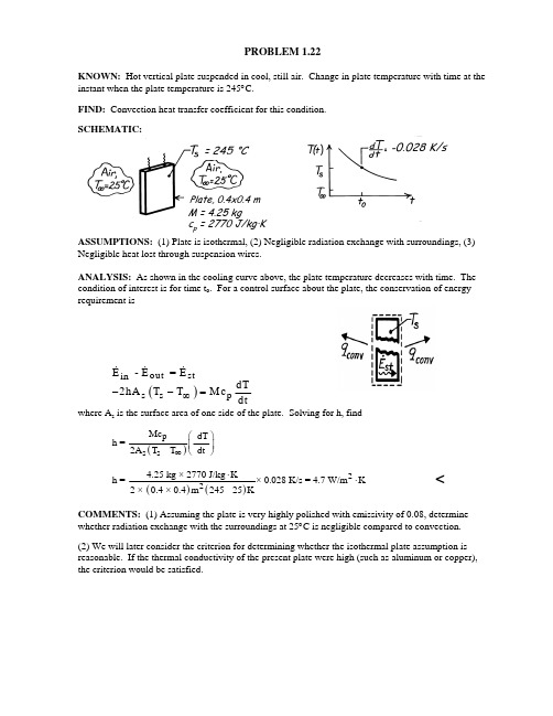
PROBLEM 1.22KNOWN: Hot vertical plate suspended in cool, still air. Change in plate temperature with time at the instant when the plate temperature is 245°C.FIND: Convection heat transfer coefficient for this condition.SCHEMATIC:ASSUMPTIONS: (1) Plate is isothermal, (2) Negligible radiation exchange with surroundings, (3)Negligible heat lost through suspension wires.ANALYSIS: As shown in the cooling curve above, the plate temperature decreases with time. The condition of interest is for time t o . For a control surface about the plate, the conservation of energy requirement is()outst in s s pE - E = E dT 2hA T T Mc dt∞−−=&&&where A s is the surface area of one side of the plate. Solving for h, find()ps s Mc -dT h =2A T - T dt ∞⎛⎞⎜⎟⎝⎠()()224.25 kg × 2770 J/kg K h = × 0.028 K/s = 4.7 W/m K 2 × 0.4 × 0.4m 245 - 25K⋅⋅<COMMENTS: (1) Assuming the plate is very highly polished with emissivity of 0.08, determinewhether radiation exchange with the surroundings at 25°C is negligible compared to convection.(2) We will later consider the criterion for determining whether the isothermal plate assumption is reasonable. If the thermal conductivity of the present plate were high (such as aluminum or copper), the criterion would be satisfied.-0.022 K/s-0.028 K/s = 245 °CPlate, 0.3×0.3 m M = 4.25 kgc p = 2770 J/kg·KPlate, 0.4x0.4 mPROBLEM 1.29KNOWN: Air and wall temperatures of a room. Surface temperature, convection coefficient and emissivity of a person in the room.FIND: Basis for difference in comfort level between summer and winter.ASSUMPTIONS: (1) Person may be approximated as a small object in a large enclosure.ANALYSIS: Thermal comfort is linked to heat loss from the human body, and a chilled feeling is associated with excessive heat loss. Because the temperature of the room air is fixed, the different summer and winter comfort levels cannot be attributed to convection heat transfer from the body. In both cases, the heat flux isSummer and Winter : ()22q h T T 2 W/m K 12 C 24 W/m convs ′′=−=⋅×=∞oHowever, the heat flux due to radiation will differ, with values of Summer : ()()448244442q T T 0.9 5.6710W/m K 305300K 28.3 W/m rads sur εσ−′′=−=××⋅−= Winter :()()448244442q T T 0.9 5.6710W/m K 305287K 95.4 W/m rad s surεσ−′′=−=××⋅−=There is a significant difference between winter and summer radiation fluxes, and the chilled condition is attributable to the effect of the colder walls on radiation.COMMENTS: For a representative surface area of A = 1.5 m 2, the heat losses are q conv = 36 W, q rad(summer) = 42.5 W and q rad(winter) = 143.1 W. The winter time radiation loss is significant and if maintained over a 24 h period would amount to 2,950 kcal.PROBLEM 1.44KNOWN: Radial distribution of heat dissipation in a cylindrical container of radioactive wastes. Surface convection conditions.FIND: Total energy generation rate and surface temperature.SCHEMATIC:ASSUMPTIONS: (1) Steady-state conditions, (2) Negligible temperature drop across thin container wall.ANALYSIS: The rate of energy generation is()()r 2g o o 022g o o o E qdV=q 1-r/r 2rLdr E 2Lqr /2r /4o ⎡⎤=⎢⎥⎣⎦=−∫∫&&&&&ππor per unit length,&&.′=E q r 2g o o 2π <Performing an energy balance for a control surface about the container yields, at an instant,&&′−′=E E g outand substituting for the convection heat rate per unit length,()()2o o o s qr h 2r T T 2∞=−&ππT T qr 4hs o o =+∞&. <COMMENTS: The temperature within the radioactive wastes increases with decreasing r from T s at r o to a maximum value at the centerline.PROBLEM 1.76KNOWN: Thickness and thermal conductivity, k, of an oven wall. Temperature and emissivity, ε, of front surface. Temperature and convection coefficient, h, of air. Temperature of large surroundings.FIND: (a) Temperature of back surface, (b) Effect of variations in k, h and ε.SCHEMATIC:ASSUMPTIONS: (1) Steady-state, (2) One-dimensional conduction, (3) Radiation exchange with large surroundings.ANALYSIS: (a) Applying an energy balance, Eq. 1.13 to the front surface and substituting the appropriate rate equations, Eqs. 1.2, 1.3a and 1.7, find()()44122sur 2T T k h T T T T Lεσ∞−=−+−.Substituting numerical values, find()()1220.05m W 448T T 20100K 240.7W/m K m K W 0.8 5.6710400K 300K 200K m K −−=⋅⋅+××−=⋅⎤⎡⎡⎤⎥⎢⎢⎥⎣⎦⎣⎦.Since 2T = 400 K, it follows that 1T = 600 K.<(b) Parametric effects may be evaluated by using the IHT First Law Model for a Nonisothermal Plane Wall. Changes in k strongly influence conditions for k < 20 W/m ⋅K, but have a negligible effect for larger values, as 2T approaches 1T and the heat fluxes approach the corresponding limiting values100200300400Thermal conductivity, k(W/m.K)300400500600T e m p e r a t u r e , T 2(K )100200300400Thermal conductivity, k(W/m.K)0200040006000800010000H e a t f l u x , q ''(W /m ^2)Conduction heat flux, q''cond(W/m^2)Convection heat flux, q''conv(W/m^2)Radiation heat flux, q''rad(W/m^2)Continued…PROBLEM 1.76 (Cont.)The implication is that, for k > 20 W/m ⋅K, heat transfer by conduction in the wall is extremely efficient relative to heat transfer by convection and radiation, which become the limiting heat transfer processes. Larger fluxes could be obtained by increasing ε and h and/or by decreasing T ∞ and sur T .With increasing h, the front surface is cooled more effectively (2T decreases), and although radq ′′ decreases, the reduction is exceeded by the increase in convq ′′. With a reduction in 2T and fixed values of k and L, condq ′′ must also increase.100200Convection coefficient, h(W/m^2.K)400500600T e m p e r a t u r e , T 2(K )100200Convection coefficient, h(W/m^2.K)0100002000030000H e a t f l u x , q ''(W /m ^2)Conduction heat flux, q''cond(W/m^2)Convection heat flux, q''conv(W/m^2)Radiation heat flux, q''rad(W/m^2)The surface temperature also decreases with increasing ε, and the increase in rad q ′′ exceeds the reduction in convq ′′, allowing cond q ′′ to increase with ε. 00.20.40.60.81Emissivity550555560565570575T e m p e r a t u r e , T 2(K )0.20.40.60.81Emissivity0200040006000800010000H e a t f l u x , q ''(W /m ^2)Conduction heat flux, q''cond(W/m^2)Convection heat flux, q''conv(W/m^2)Radiation heat flux, q''rad(W/m^2)COMMENTS: Conservation of energy, of course, dictates that irrespective of the prescribed conditions, cond conv radq q q ′′′′′′=+.PROBLEM 1.77KNOWN: Temperatures at 15 mm and 30 mm from the surface and in the adjoining airflow for a thick stainless steel casting.FIND: Surface convection coefficient, h. SCHEMATIC:ASSUMPTIONS: (1) Steady-state, (2) One-dimensional conduction in the x-direction, (3) Constant properties, (4) Negligible generation.ANALYSIS: From a surface energy balance, it follows that′′=′′q q cond convwhere the convection rate equation has the form()0convq h T T ,∞′′=−and ′′q cond can be evaluated from the temperatures prescribed at surfaces 1 and 2. That is, from Fourier’s law,()()12cond212condT T q k x x 6050C Wq 1510,000 W/m .m K 30-1510m−′′=−−′′==⋅×oSince the temperature gradient in the solid must be linear for the prescribed conditions, it follows thatT o = 70°C. Hence, the convection coefficient ish =q T T cond 0′′−∞2210,000 W/m h 333 W/m K 30°C==⋅<COMMENTS: The accuracy of this procedure for measuring h depends strongly on the validity of the assumed conditions.T 1= 60°C T 2= 50°C 3015PROBLEM 1.81KNOWN: Conditions associated with surface cooling of plate glass which is initially at 600°C. Maximum allowable temperature gradient in the glass.FIND: Lowest allowable air temperature, T ∞.SCHEMATIC:ASSUMPTIONS: (1) Surface of glass exchanges radiation with large surroundings at T sur = T ∞, (2) One-dimensional conduction in the x-direction.ANALYSIS: The maximum temperature gradient will exist at the surface of the glass and at the instant that cooling is initiated. From the surface energy balance, Eq. 1.13, and the rate equations, Eqs. 1.1, 1.3a and 1.7, it follows that()()44s s sur dT -kh T T T T 0dxεσ∞−−−−=or, with (dT/dx)max = -15°C/mm = -15,000°C/m and T sur = T ∞,()C 2W W1.415,0005873T K m K m m K ∞⎡⎤−−=−⎢⎥⋅⎢⎥⋅⎣⎦o844424W0.8 5.6710873T K .m K −∞⎡⎤+××−⎢⎥⎣⎦⋅T ∞ may be obtained from a trial-and-error solution, from which it follows that, for T ∞ = 618K,21000127519730,,.W m W m Wm222≈+Hence the lowest allowable air temperature isT K =345C.∞≈618o<COMMENTS: (1) Initially, cooling is determined primarily by radiation effects.(2) For fixed T ∞, the surface temperature gradient would decrease with increasing time into the cooling process. Accordingly, T ∞ could be decreasing with increasing time and still keep within themaximum allowable temperature gradient.。
通风系统中的气流动态建模改进

通风系统中的气流动态建模改进1. IntroductionIn recent years, the importance of indoor air quality has become increasingly recognized, especially in commercial and residential buildings where occupants spend the majority of their time. One key factor that significantly impacts indoor air quality is the efficiency and effectiveness of the ventilation system in place. The ventilation system is responsible for the distribution of fresh air and the removal of indoor pollutants, ensuring a healthy and comfortable indoor environment. In this context, the dynamic modeling of airflow in ventilation systems plays a crucial role in optimizing their performance.2. Importance of Dynamic ModelingConventional static models of airflow in ventilation systems are based on simplified assumptions and do not fully capture the complex dynamics of airflow in real-world conditions. Dynamic modeling, on the other hand, takes into account the transient nature of airflow, considering factors such as ventilation rates, temperature differentials, occupant activities, and external weather conditions. By incorporating these variables into the modeling process, engineers and researchers can gain a more comprehensive understanding of how airflow behaves in a given space, allowing for more accurate predictions and better decision-making.3. Challenges in Dynamic ModelingDespite its advantages, dynamic modeling of airflow inventilation systems presents several challenges that must be addressed to improve its accuracy and reliability. One of the main challenges is the complexity of the airflow patterns, which can vary significantly depending on the specific layout and configuration of the ventilation system. Additionally, the interaction between airflow and other building systems, such as heating and cooling systems, further complicates the modeling process. To overcome these challenges, researchers are developing advanced simulation tools and computational algorithms that can more effectively capture the dynamics of airflow in ventilation systems.4. Simulation Tools and TechniquesNumerical simulation has emerged as a powerful tool for studying airflow dynamics in ventilation systems. Computational fluid dynamics (CFD) software, in particular, allows engineers to create virtual models of indoor spaces and simulate airflow under different operating conditions. By solving the governing equations of fluid flow and heat transfer, CFD models can provide detailed insights into airflow patterns, temperature distributions, and pollutant dispersion within a building. These simulations enable engineers to optimize the design of ventilation systems, evaluate the effectiveness of control strategies, andidentify potential areas for improvement.5. Integration with Building Automation SystemsAnother important trend in the field of ventilation system modeling is the integration of dynamic models with building automation systems (BAS). BAS are sophisticated controlsystems that monitor and regulate various building functions, including heating, cooling, lighting, and ventilation. By connecting dynamic airflow models to BAS, engineers can implement real-time control strategies that respond to changes in occupancy, outdoor conditions, and equipment operation. This integration enhances the overall performance of the ventilation system, ensuring optimal air quality and energy efficiency.6. Case Studies and ApplicationsSeveral case studies have demonstrated the effectiveness of dynamic modeling in improving the performance of ventilation systems. For example, researchers have used CFD simulations to optimize the layout of air supply diffusers in office buildings, achieving better air distribution and thermal comfort for occupants. In healthcare facilities, dynamic modeling has been employed to design isolation rooms with controlled airflow patterns to prevent the spread of airborne infections. These applications highlight the versatility and value of dynamic modeling in addressing specific challenges and requirements in different building types.7. Future Directions and Research OpportunitiesLooking ahead, there are several promising researchdirections that can further enhance the capabilities of dynamic modeling in ventilation systems. One area of interest is the integration of sensor data and machine learning algorithms to create adaptive control systems that can continuously optimize airflow in response to changing conditions. Additionally, the development of multi-scalemodels that combine macroscopic and microscopic approaches can provide a more comprehensive understanding of airflow dynamics at different spatial and temporal scales. By exploring these and other research opportunities, engineers and researchers can continue to advance the field of ventilation system modeling and contribute to the creation of healthier and more sustainable indoor environments.8. ConclusionIn conclusion, dynamic modeling of airflow in ventilation systems is a critical tool for optimizing indoor air quality and energy performance in buildings. By accurately capturing the transient behavior of airflow and considering the interaction of various factors, dynamic models can help engineers design more effective ventilation systems, improve occupant comfort, and reduce energy consumption. As research in this field progresses and new technologies emerge, the potential for innovation and impact in the built environment will only continue to grow.。
SOLIDWORKS Flow Simulation 产品说明书
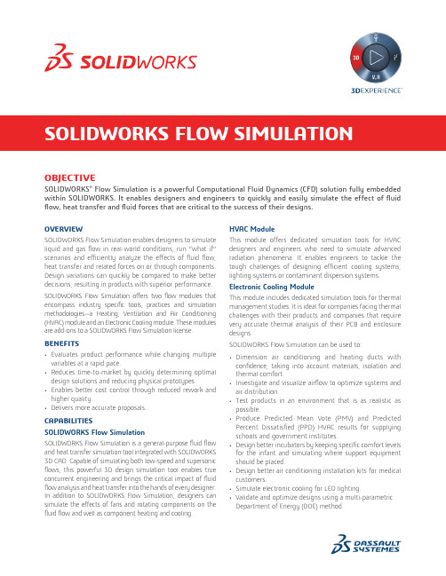
OBJECTIVESOLIDWORKS® Flow Simulation is a powerful Computational Fluid Dynamics (CFD) solution fully embedded within SOLIDWORKS. It enables designers and engineers to quickly and easily simulate the effect of fluid flow, heat transfer and fluid forces that are critical to the success of their designs.OVERVIEWSOLIDWORKS Flow Simulation enables designers to simulate liquid and gas flow in real-world conditions, run “what if” scenarios and efficiently analyze the effects of fluid flow, heat transfer and related forces on or through components. Design variations can quickly be compared to make better decisions, resulting in products with superior performance. SOL IDWORKS Flow Simulation offers two flow modules that encompass industry specific tools, practices and simulation methodologies—a Heating, Ventilation and Air Conditioning (HVAC) module and an Electronic Cooling module. These modules are add-ons to a SOLIDWORKS Flow Simulation license. BENEFITS• Evaluates product performance while changing multiple variables at a rapid pace.• Reduces time-to-market by quickly determining optimal design solutions and reducing physical prototypes.• Enables better cost control through reduced rework and higher quality.• Delivers more accurate proposals.CAPABILITIESSOLIDWORKS Flow SimulationSOLIDWORKS Flow Simulation is a general-purpose fluid flow and heat transfer simulation tool integrated with SOLIDWORKS 3D CAD. Capable of simulating both low-speed and supersonic flows, this powerful 3D design simulation tool enables true concurrent engineering and brings the critical impact of fluid flow analysis and heat transfer into the hands of every designer. In addition to SOL IDWORKS Flow Simulation, designers can simulate the effects of fans and rotating components on the fluid flow and well as component heating and cooling. HVAC ModuleThis module offers dedicated simulation tools for HVAC designers and engineers who need to simulate advanced radiation phenomena. It enables engineers to tackle the tough challenges of designing efficient cooling systems, lighting systems or contaminant dispersion systems. Electronic Cooling ModuleThis module includes dedicated simulation tools for thermal management studies. It is ideal for companies facing thermal challenges with their products and companies that require very accurate thermal analysis of their PCB and enclosure designs.SOLIDWORKS Flow Simulation can be used to:• Dimension air conditioning and heating ducts with confidence, taking into account materials, isolation and thermal comfort.• Investigate and visualize airflow to optimize systems and air distribution.• Test products in an environment that is as realistic as possible.• Produce Predicted Mean Vote (PMV) and Predicted Percent Dissatisfied (PPD) HVAC results for supplying schools and government institutes.• Design better incubators by keeping specific comfort levels for the infant and simulating where support equipment should be placed.• Design better air conditioning installation kits for medical customers.• Simulate electronic cooling for LED lighting.• Validate and optimize designs using a multi-parametric Department of Energy (DOE) method.SOLIDWORKS FLOW SIMULATIONOur 3D EXPERIENCE® platform powers our brand applications, serving 12 industries, and provides a rich portfolio of industry solution experiences.Dassault Syst èmes, t he 3D EXPERIENCE® Company, provides business and people wit h virt ual universes t o imagine sust ainable innovat ions. It s world-leading solutions transform the way products are designed, produced, and supported. Dassault Systèmes’ collaborative solutions foster social innovation, expanding possibilities for the virtual world to improve the real world. The group brings value to over 220,000 customers of all sizes in all industries in more than 140 countries. For more information, visit .Europe/Middle East/Africa Dassault Systèmes10, rue Marcel Dassault CS 4050178946 Vélizy-Villacoublay Cedex France AmericasDassault Systèmes 175 Wyman StreetWaltham, Massachusetts 02451-1223USA Asia-PacificDassault Systèmes K.K.ThinkPark Tower2-1-1 Osaki, Shinagawa-ku,Tokyo 141-6020Japan©2018 D a s s a u l t S y s t èm e s . A l l r i g h t s r e s e r v e d . 3D E X P E R I E N C E ®, t h e C o m p a s s i c o n , t h e 3D S l o g o , C A T I A , S O L I D W O R K S , E N O V I A , D E L M I A , S I M U L I A , G E O V I A , E X A L E A D , 3D V I A , B I O V I A , N E T V I B E S , I F W E a n d 3D E X C I T E a r e c o m m e r c i a l t r a d e m a r k s o r r e g i s t e r e d t r a d e m a r k s o f D a s s a u l t S y s t èm e s , a F r e n c h “s o c i ét é e u r o p ée n n e ” (V e r s a i l l e s C o m m e r c i a l R e g i s t e r # B 322 306 440), o r i t s s u b s i d i a r i e s i n t h e U n i t e d S t a t e s a n d /o r o t h e r c o u n t r i e s . A l l o t h e r t r a d e m a r k s a r e o w n e d b y t h e i r r e s p e c t i v e o w n e r s . U s e o f a n y D a s s a u l t S y s t èm e s o r i t s s u b s i d i a r i e s t r a d e m a r k s i s s u b j e c t t o t h e i r e x p r e s s w r i t t e n a p p r o v a l .• Free, forced and mixed convection• Fluid flows with boundary layers, including wall roughness effects• Laminar and turbulent fluid flows • Laminar only flow• Multi-species fluids and multi-component solids• Fluid flows in models with moving/rotating surfaces and/or parts• Heat conduction in fluid, solid and porous media with/without conjugate heat transfer and/or contact heat resistance between solids• Heat conduction in solids only • Gravitational effectsAdvanced Capabilities• Noise Prediction (Steady State and Transient)• Free Surface• Radiation Heat Transfer Between Solids • Heat sources due to Peltier effect• Radiant flux on surfaces of semi-transparent bodies• Joule heating due to direct electric current in electrically conducting solids• Various types of thermal conductivity in solid medium • Cavitation in incompressible water flows• Equilibrium volume condensation of water from steam and its influence on fluid flow and heat transfer• Relative humidity in gases and mixtures of gases • Two-phase (fluid + particles) flows • Periodic boundary conditions.• Tracer Study• Comfort Parameters • Heat Pipes • Thermal Joints• Two-resistor Components • PCBs•Thermoelectric Coolers• Test the heat exchange on AC and DC power converters.• Simulate internal temperature control to reduce overheating issues.• Better position fans and optimize air flux inside a design.• Predict noise generated by your designed system.Some capabilities above need the HVAC or Electronic Cooling Module.SOLIDWORK Design Support• Fully embedded in SOLIDWORKS 3D CAD• Support SOLIDWORKS configurations and materials • Help Documentation • Knowledge base• Engineering database• eDrawings ® of SOLIDWORKS Simulation results General Fluid Flow Analysis• 2D flow • 3D flow • Symmetry• Sector Periodicity • Internal fluid flows • External fluid flowsAnalysis Types• Steady state and transient fluid flows • Liquids • Gases• Non-Newtonian liquids • Mixed flows• Compressible gas and incompressible fluid flows •Subsonic, transonic and supersonic gas flowsMesher• Global Mesh Automatic and Manual settings • Local mesh refinementGeneral Capabilities• Fluid flows and heat transfer in porous media • Flows of non-Newtonian liquids • Flows of compressible liquids •Real gases。
Fluid-Structure Interaction

Fluid-Structure Interaction Fluid-structure interaction (FSI) is a complex and fascinating phenomenon that occurs when the motion of a fluid affects the behavior of a nearby structure, and vice versa. This interaction has significant implications in various engineering and scientific fields, including aerospace, civil engineering, biomechanics, and oceanography. Understanding and effectively managing FSI is crucial for the design and performance of numerous systems and structures. In this response, we will explore the multifaceted nature of FSI, considering its impact, challenges, and potential solutions from different perspectives. From an engineering standpoint, FSI presents both opportunities and challenges. On one hand, harnessing FSI can lead to innovative designs and improved performance in a wide range of applications. For example, in aerospace engineering, FSI considerations arecritical for optimizing the aerodynamic performance of aircraft and spacecraft. By accounting for the interaction between the airflow and the structural components, engineers can develop more efficient and stable designs. Similarly, in civil engineering, understanding FSI is essential for designing resilient structuresthat can withstand the forces exerted by wind, water, or seismic events. By integrating FSI analysis into the design process, engineers can enhance the safety and longevity of infrastructure. However, managing FSI also poses significant challenges. The complex and nonlinear nature of fluid-structure interactions makes accurate prediction and analysis difficult. Engineers and researchers oftengrapple with the intricacies of FSI, including turbulence, boundary layer effects, and structural deformation. These challenges are further compounded in scenarios involving multiphysics phenomena, such as the interaction between fluid flow, heat transfer, and structural dynamics. As a result, there is a pressing need for advanced computational tools, experimental techniques, and theoretical models to improve our understanding and control of FSI. In the realm of scientific research, FSI serves as a rich area of exploration, offering insights into fundamental principles of fluid dynamics and structural mechanics. From studying the biomechanics of human physiology to investigating the behavior of marine ecosystems, FSI phenomena are pervasive in the natural world. For instance, in cardiovascular research, understanding the interaction between blood flow andarterial walls is crucial for diagnosing and treating vascular diseases. By simulating FSI scenarios, scientists can gain a deeper understanding of physiological processes and develop new medical interventions. Moreover, FSI plays a pivotal role in the study of ocean dynamics and environmental phenomena. The interaction between ocean currents, waves, and coastal structures has profound implications for coastal erosion, offshore engineering, and marine ecology. By examining FSI in these contexts, researchers can contribute to the sustainable management of coastal resources and the protection of vulnerable ecosystems. Furthermore, the insights gained from studying FSI in natural systems can inspire innovative solutions for engineering challenges, leading to the development ofbio-inspired designs and technologies. In addressing the complexities of FSI, interdisciplinary collaboration is essential. Engineers, physicists, mathematicians, and computer scientists must work together to develop comprehensive approaches for analyzing and simulating FSI phenomena. Byintegrating expertise from diverse fields, researchers can leverage advanced computational methods, such as finite element analysis, computational fluid dynamics, and coupled multiphysics simulations, to tackle FSI challenges. Furthermore, experimental validation and data-driven approaches are critical for refining FSI models and ensuring their accuracy in real-world scenarios. In conclusion, fluid-structure interaction is a multifaceted and significant aspect of engineering and scientific research. While it presents opportunities for innovation and discovery, it also poses formidable challenges that demand concerted efforts from the research community. By embracing a holistic and collaborative approach, we can advance our understanding of FSI, develop robust computational tools, and unlock new possibilities for designing resilient and efficient systems. Ultimately, the exploration of FSI holds great promise for addressing real-world problems and shaping the future of engineering and science.。
制作变压器散热片流程
制作变压器散热片流程英文回答:Making a transformer heat sink involves several stepsto ensure effective heat dissipation and optimal performance. The process typically includes the following steps:1. Design and material selection: The first step is to determine the design and dimensions of the heat sink based on the transformer's specifications and heat dissipation requirements. The material selection is crucial as itshould have good thermal conductivity, corrosion resistance, and mechanical strength. Commonly used materials include aluminum, copper, and their alloys.2. Heat sink fabrication: Once the design and material are finalized, the heat sink is fabricated. This involves cutting, shaping, and forming the material into the desired shape and size. Various techniques such as machining,extrusion, or casting can be used depending on the complexity of the design and the chosen material.3. Surface treatment: To enhance heat transfer and improve corrosion resistance, the heat sink's surface is often treated. Anodizing or electroplating can be appliedto aluminum heat sinks, while copper heat sinks may undergo chemical treatment or coating.4. Fin creation: Fins are an essential part of the heat sink, increasing the surface area for better heat dissipation. The fins can be created by cutting, stamping,or extruding the heat sink material. The shape and size of the fins are designed to maximize airflow and heat transfer.5. Assembly: Once the heat sink and fins are ready,they are assembled onto the transformer. This may involve attaching the heat sink using screws, clips, or thermal adhesive. Care should be taken to ensure proper alignment and contact between the heat sink and the transformer surface.6. Testing and optimization: After assembly, the transformer with the heat sink undergoes testing toevaluate its heat dissipation performance. If necessary, adjustments can be made to optimize the heat sink design or improve airflow around the transformer.中文回答:制作变压器散热片涉及多个步骤,以确保有效散热和最佳性能。
TBS UNIFY PRO32 说明书
High q uality, l icense-free, u ltra-tiny V TXRevision 2021-03-29The T BS U NIFY P RO32 i s a s uccessor t o t he m ost p opular l ine o f v ideo t ransmitters (TBS U NIFY P RO). W e have i mproved t he r obustness, d ecreased t he s ize a nd p ower c onsumption, a dded c apability f or i nsane features a nd p erfected t he w ay i t i s i nstalled i n y our m ultirotor. I n a n utshell, i t’s t he m ost c omprehensive, future p roof, h ighest q uality a nd o verall b est V TX l ine m ade t o d ate.Key f eatures: M ain f eatures a cross a ll U nify P ro32 m odels•World’s l ightest 37ch v ideo t ransmitter l ine (custom c hannels v ia S martaudio a nd C RSF)•Power t o C hannel c alibration f or e ach c hannel -e xtremely c onsistent o utput p ower•25mW (more p ower a vailable, r equires H AM l icense*)•One b utton f requency a nd p ower s etup•OSD c onfiguration u sing T BS S martAudio 2.1 (via F C, T BS C rossfire/ T racer o r P NP P RO O SD)•LUA s upport f or C RSF u sers•U.FL c onnector (Unify P RO32 n ano)•MMCX c onnector (Unify P RO32 H V)•1-3S i nput o r 2-6S i nput w ith 5V o utput v ersions a vailable•Improved n oise f iltering•Double n oise f iltering (Unify P RO32 H V)•Optimized h eat d issipation•Solder-on m odule d imensions a vailable o n r equestTable o f C ontentsTable o f C ontentsSpecificationsAttentionFAQNoteUpdatingOverviewButton m enu c ontrolUnlock &p ower s elect m odeButton m enu s tructureMenu T ableChannel/ B and -F requency T able Installation /M ountingControl b y F light C ontrollers (Smartaudio)Control b y C rossfire/ T racer d irect c onnection Crossfire/Tracer c onnection u sing S martaudioCrossfire/Tracer c onnection u sing C RSFSmart A udio o r C RSF f or t he V TX?Button n ot w orkingControl b y P WM c hannel (Unify P RO32 N ano o nly) Video t ransmitter p inoutTBS U NIFY P RO32 5G8 n anoTBS U NIFY P RO32 H V 5G8Barcode C ontrolTechnology s howcasePITModeSmartAudio 2.1CRSFCleanSwitchForce d evice i nto b ootloader m ode SpecificationsTBS U NIFY P RO32 5G8 n ano TBS U NIFY P RO32 H V (MMCX) Input v oltage: 1S -3S L iPo3V -13V2S -6S L iPo6V -36VPower O utput Input V oltage -L C f ilter -O utput v oltage(pass t hrough, f ollowing i nput v oltage)Regulated a nd f iltered 5V /2AExtra f eatures: CleanSwipePITMode (incl. S upport f or t eam r acing)Full C RSF c apability (Serial c ommands f or e xternal c ontrol)SoftwareprotocolSmartAudio V2.1CRSFOutput P ower 14dBm (25mW)20dBm (100mW*)26dBm (400mW*)28dBm (600mW*) (Rev 1.1)14dBm (25mW)20dBm (100mW*)26dBm (400mW*)30dBm (1000mW*)Pit m ode Activate: P ress p ower d uring s tartupor u se S mart A udio V2.1LED f lashes r ed w hen e nabledDisable /D eactivate: P ress p ower f or 5s econds d uring r untimeOr u se S mart A udio V2.1Pit m ode -> f lightmodeOn-board b utton, S martAudio 2.1 o r C RSF C ommandChannels: Band A(8ch), B(8ch), E(5ch)Fatshark 8ch, R ace B and 8chAudio o n 6.5MHz No Yes, b uilt i n M icrophonePower c onsumption 25mW: 210mA100mW: 280mA400mW: 390mA25mW: 90mA -130mA (22V -14.8V)100mW: 120mA -170mA (22V -14.8V)400mW: 180mA -270mA (22V -14.8V)1000mW+: 300mA -450mA (22V -14.8V)Range: 2km (omni) 6km (omni)80km+ (directional)Antenna c onnector: u.FL h igh s trength MMCXPort c onnector Through-holes, 2mm p itch JST-GH 7p inDimensions: 14.5(L) x13(W) x3(H) m m 37(L) x25(W) x6(H) m mWeight: 1g 9.2gFirmware u pgrade No YesThrough U SB v ia T BS A gentKit c ontents: TBS U NIFY P RO32 N ANOu.FL A ntennaSilicon C ables p re- t innedTBS U NIFY P RO32MMCX t o S MA P igtailJST-GH 7pin S ilicon C able, e nds p re- t inned* r equires H AM l icense, s pecial u nlocking p rocedure, a vailable o n s elected m odels o nly!AttentionThese v ideo t ransmitters a re c apable o f r adio f requency t ransmissions a nd o utput p ower t hat m ay b e n ot allowed i n y our c ountry.Please a lways c heck y our l ocal R F l egislation t o s et t he f requency a nd o utput p ower a ccording t o the r egulation.A g eneral r ule f or R C a ircrafts i s t hat t hey m ust b e c ontrolled a lways u nder s ight o f v iew, c heck y our R C regulation t o k eep u p t o d ate w ith r egulations.FAQIf y ou g ot a ny q uestion a fter r eading t his m anual y ou s hould v isit t he T BS F AQ s ectionNoteThis m anual i s w ritten b ased o n F W 1.16 .I f s ome f unctions a re n ot a vailable f or y ou, p lease u pdate y our Unify t o t hese o r l ater v ersions.UpdatingIn o rder t o u pdate y our U nify32 (not N ano32) y ou n eed t he T BS A gent X, w hich y ou c an d ownload f rom the T BS s hop .To u pdate y our V TX, c onnect i t b y t he U SB-port a nd r un t he u pdate b y A gent X.For d etailed i nstructions o n h ow t o u se A gent X, h ave a l ook a t t he A gent X m anual .OverviewNano32Pro32Button m enu c ontrolThe m enu c onsists o f c ategories a nd s ettings. P ressing t he b utton f or 3s econds w ill t oggle b etween categories, p ressing i t f or a s hort t ime t oggles b etween s ettings. T o e nter t he m enu, h old t he b utton f or 3 seconds. L ED c olors w ill s ignal t he s tate o f t he m enu, f or a n o verview s ee t he m enu t able .Unlock &p ower s elect m ode(FOR H AM U SERS O NLY!) P ress t he b utton f or a bout 30 s econds. T he R ed L ED w ill f lash 3t imes t o c onfirm. You h ave u nlocked t he v ideo t ransmitter f or u se w ith a ll f requencies (see f requency t able b elow). NOTE :U nlock o nly w orks i f y ou a re i nside t he b and s election m enuThe p ower s elect m ode i s n ow a ccessible. O nce u nlocked, y ou c an s elect t he p ower l evel a ccording t o t he table b elow. T o l ock t he t ransmitter, g o b ack i nto b and s elect m enu a nd p ress t he b utton f or 20 t o 25 seconds a gain.Button m enu s tructureFor U nify P RO32 H VFor U nify P RO32 N anoThe T BS U NIFY P RO32 5G8 s ignals s elected c hannel, b and a nd p ower l evels u sing a s tartup s equence o f LED c odes. T he s ame s equence i s a lso r epeated i n t he m enu t o m ake i t u nified. F irst t he R ED L ED f lashes t o indicate t he i tem b eing s hown. O ne f lash f or c hannel, t wo f lashes f or b and, t hree f lashes f or p ower l evel. Subsequently, t he B LUE L ED w ill i ndicate t he v alue.Menu T able* U nify P RO32 H V o nly** U nify P RO32 N ano o nlyRed L ED: Indicate i tem - C hannel, b and o r p ower s etting Blue L ED: Indicate v alueRED L ED BLUE L ED1x 2x 3x 4x 5x 6x 7x 8x 1x Channel 1 2 3 456 7 8 2x BandAB E Airwave Race 3x Power L evel 25mW 100mW 400mW 1000mW 4x Limit T emp. 60 70 80 90 100 105 5x PIT M ode OFF IN-BAND6x CRSF/SA/PWM OFFCRSF SA PWM**7x *Audio (Mic)OFFONChannel/ B and -F requency T ableChannel 1 2 3 4 5 6 7 8Band A 5865 5845 5825 5805 5785 5765 5745 5725 MHz Band B 5733 5752 5771 5790 5809 5828 5847 5866 MHz Band E 5705 5685 5665 5645 5885 5905 5925 5945 MHz Airwave 5740 5760 5780 5800 5820 5840 5860 5880 MHz Race B and 5658 5695 5732 5769 5806 5843 5880 5917 MHzPower L evel 25 100 400 1000+ mWGrey f ields a re t he d efault f actory s etting.The s elections i n o range r equires H AM l icense t o o perate l egally. B lack s elections a re o nly a vailable o n special r equest (custom f irmware f or l arge e vents w ith p rior l egal b ody a pproval). T he v ideo t ransmitter ensures t hat y ou c annot s elect i llegal c hannels o r p ower l evels b y a ccident:●When c ontrolled b y t he p ush b utton, y ou w ill n eed t o c onfirm h aving a H AM l icense b y f ollowingthe s teps d escribed a bove t o u nlock y our v ideo t ransmitter●Through t he C ORE P RO, y ou a re r equired t o e nter y our H AM l icense n umber u nder t he “Callsign”menu b efore y ou c an a ccess t he h igh p ower t ransmission s ettings a nd t he l ocked o ut c hannelsInstallation /M ountingWhen i nstalling t he U nify P ro32, p lease e nsure a dequate a irflow a nd -m ost i mportantly -h eat t ransfer. This m eans m ounting t he U nify P ro32 w ith a b it o f p ressure a gainst a f lat p iece o f c arbon w ill g ive y ou t he best r esults. M ake s ure t o i solate t he c ontacts o f t he U nify a gainst t he c arbon t o a void s hort c ircuits. Proper m ounting w ill a llow t he v ideo t ransmitter t o r un f or e xtended p eriods o f t ime w hile s itting o n t he ground a nd w ithout r educing o utput p ower. T BS U NIFY P RO32 a utomatically r educes o utput p ower b efore it r eaches c ritical h eat l evels.PinoutTBS U NIFY P RO32 5G8 n anoThe U NIFY P RO32 5G8 N ano c omes w ith p re i nstalled s ilicon w ires f or e asy i nstallation i n y our b uild. T here is a f iltered 3-13V i nput w ith a p ass t hrough o utput f or y our c amera o r o ther d evices.ATTENTION!●Please t ake c are w hen s oldering t o t he t abs, d o n ot s older w ith t emperatures h igher t han 350°Cfor m ore t han 3-5sec.●For r emote c ontrol o f t he V TX c hannels w e s uggest u sing S martAudio o r C RSF i nterface. T he t actilebutton i s v ery f ragile, d o n ot u se h ard a nd p ointy o bjects s uch a s n eedles t o c hange c hannels t oprevent p ermanent d amage t o t he b utton.●If y ou p lan t o u se t he V TX o n 13v m ake s ure t o u se a p roper f iltering a s a ny v oltage s pike w illdamage i t.TBS U NIFY P RO32 H V 5G8The U NIFY P RO32 5G8 H V c omes w ith a c able a ssembly w ith s ilicon w ires f or e asy i nstallation i n y our build. T here i s a f iltered 5V o utput f or y our c amera.The i nstalled S tep D own c onverter i s a n ew, m ore p owerful D CDC a nd i s c apable o f p owering m ost 5V cameras o n t he m arket.Control b y F light C ontrollers (Smartaudio)Using a ny S mart A udio V2.1 c ompatible f light c ontroller s imply c onnect t he S mart A udio d ata p in t o a f ree and s upported p ort o n y our F C (see p inout b elow).For B etaflight u sers, y ou c an t hen c onfigure t he c onnected p ort i n B etaflight c onfigurator t o S mart A udio V2.1 p rotocol. I deally y ou m ake s ure t o g et a B etaflight f irmware w hich s upports t he n ew S A2.1 (Betaflight >=V3.5.6) r ather t han t he o lder S A2.0. T his w ay y ou g et a ccess t o t he n ew p ower l evels o f S A2.1.If y ou u se B F 4.xx o r l ater, y ou n eed t o a dd t he V TX t able. Y ou c an d ownload t he V TX t ables f or a ll T BS UNIFY V TXs h ere .Control b y C rossfire/ T racer d irect c onnectionYour T BS C rossfire/ T racer c an c ontrol y our T BS U nify P ro32 d irectly w ithout t he n eed f or a F C. T his i s helpful w hen y ou d on’t h ave a F C i n y our a ircraft, g ot n o f ree U ART l eft o r j ust d on’t w ant t o c ontrol t he Unify32 w ithout a ny e xtra s etup r equired.For d etails o n h ow t he C rossfire/ T racer c an b e s et u p, v isit t he C rossfire m anual o r t he T racer m anual .Crossfire/Tracer c onnection u sing S martaudioYou c an c onnect y our U nify P ro32 t o a ny C rossfire/ T racer r eceiver. T he V TX w ill t hen b e c ontrolled b y t he Agent L ite b y t he M y V TX m enu o r i n t he V TX m enu o f t he r eceiver:●Set t he U nify t o S martaudio b y t he b utton●Select a f ree o utput p in c apable f or S A●Connect t hem (Crossfire/ T racer S A T X t o V TX R X/ S martAudio p ad) C rossfire/Tracer c onnectionusing S martaudioWiring e xampleNow y ou c an c ontrol y our U nify b y t he M y V TX m enu o r b y t he V TX m enu o f t he r eceiver b y A gent L ite e tc.Crossfire/Tracer c onnection u sing C RSFAll U nify P RO32 d o h ave a f ull s erial i nterface w hich h as e xtended f unctionality c ompared t o S martaudio which i s j ust a o newire p rotocol.●Set t he U nify t o C RSF b y t he b utton●Select a f ree o utput p in p air c apable f or C RSF●Connect t hem (Crossfire/ T racer S A T X t o V TX R X/ S martAudio p ad) C rossfire/Tracer c onnectionusing S martaudioWiring e xampleNow y ou c an c ontrol y our U nify b y t he M y V TX m enu o r b y i t’s o wn d evice m enu b y A gent l ite e tc.Smart A udio o r C RSF f or t he V TX?Both p rotocols h ad t heir a dvantages a nd d isadvantages:●SmartAudio○Single w ire c onnection. S aves o ne P WM o utput (useful o n a w ing)●CRSF○Full y c onfigurable b y L UA, F USION, A gent X, e tc.○CRSF r eadout -l et y ou u se P ITMode o n a s witch o r n avigate t hrough t he U nify E vo OSD w ithout t he n eed f or a f c, l ink s tats r eadout w ith t he U nify E VO O SDButton n ot w orkingWhen t he U nify P ro32 d etects a s ignal o n t he R X p ad, i t w ill d isable t he b utton. T o c hange t he V TX t o C RSF or S A, y ou c an u nsolder t he w ire o r f orce y our C rossfire/ T racer R X t o n ot o utput a ny s ignal.●Set t he o utput o f t he T racer R X t o C H X(PWM) f or t he p in t he V TX i s c onnected t o●Shut d own t he T racer T X a nd R X●Power u p j ust t he d rone w ith t he T racer R X a nd t he U nify P ro32●Change t he U nify P ro32 s ettings b y t he b utton●Turn t he t ransmitter b ack o n●Set t he o utput m ap b ack t o C RSF o r S martAudioOn t he H V v ersion t his c an b e d one b y t he A gent X a s i t g ot a U SB p ortIf y ou h ave s et u p e verything c orrectly, y ou s hould s ee t he U nify32 i n t he L ua s cript, T ango d evice m enu o r the C rossfire o led d isplay (FW 3.21 o r l ater r equired).Control b y P WM c hannel (Unify P RO32 N ano o nly)This i s a s implified m ethod t o u se a s ingle c hannel a s a b utton t o m odify t he V TX c hannel, d epending o n the r adio c ontroller y ou m ay n eed t o r everse t he c hannel o utput. C onnect t he P WM o utput f rom y our receiver t o t he S martaudio/CRSF R X p in. T he o perations a re a s f ollows:●Short p ush t he b utton t o i ncrease c hannel.●Long p ush t he b utton (>3s )t o i ncrease b and.●Longer p ush t he b utton (>5s )t o r eset V TX c hannel t o A1.Barcode C ontrolThe v ideo t ransmitter c an b e c ontrolled v ia b arcodes t hrough y our c amera. T his a llows y ou t o e nable PITMode, a nd p ower u p y our v ideo t ransmitter b y h olding t he b arcode i n f ront o f y our c amera. O r s implyto c arry y our f avorite c hannel i n y our p ocket o r o n y our b ackpack a nd r evert t o t hat c hannel e asily a ndquickly.You c an d ownload a P DF b arcode c atalog f rom t his l ink:●/tbs-VTX-barcodes.pdfAndroid a pp:●https://noahwaldner.ch/en/tbs-barcode-generator●https://apocolipse.github.io/UnifyEvoBarcodeGenerator/Raw .json f ile:●/barcodesWe a re a lways e xpanding t he f unctionality. I f y ou h ave a ny c razy i deas f or i mplementing b arcodes f or y ourraces o r o ther p urposes, p lease l et u s k now! W e’re h appy t o e xpand t he f unctionality a t a ll t imes!15Technology s howcasePITModePITMode i s a m ode w here t he v ideo t ransmitter o nly r uns o n a n i ncredibly l ow o utput p ower. T his prevents i nterference w ith o thers a t e vents, w hile s till a llowing a m inimum o f v isibility f or e mergency last-minute s etting c hanges.With t he T BS U NIFY P RO32 l ine, P it M ode h as b een s lightly m odified i n b ehavior. T he m ain b utton o n t he video t ransmitter i s u sed t o t oggle P ITMode f lag a t p ower-up, a nd S martAudio /C RSF c an m odify t his f lag as w ell. S mart A udio c an a lso e nter p it m ode d uring r untime u sing t he p ower s etting 0mW, w hich w ill n ot modify t he f lag (the V TX w ill n ever p ower u p a t t he 0mW p ower s etting). T o l eave P ITMode d uring operation, s imply s et y our d esired p ower s etting u sing S mart A udio, C RSF o r t he b utton m enu.SmartAudio 2.1SmartAudio i s a p rotocol d eveloped b y T BS f or O SD t o V TX c ommunication. S martAudio i s a s ingle-wire UART p rotocol, r unning o ver t he (Audio)-wire. A ll n ewer g eneration O SDs a t T BS, a nd a ll U NIFY P RO s eries VTX, a nd a ll m odern f light c ontrollers s upport S martAudio!With t he U NIFY P RO32 l ine w e h ave l aunched S martAudio V2.1. O ver t he r egular S martAudio, i t c hanged control f or P ITMode i n o peration t o a s witch(on /o ff) r ather t han a f lag t hat i s r efreshed o n r eboot.If y ou a re a n O SD o r V TX d eveloper i nterested i n a dding s upport f or S martAudio, p lease c heck o ur SmartAudio s pecification .S martAudio i s a f ree-to-use p rotocol. I f y ou’d l ike t o u se “TBS S martAudio” i n your m arketing, y ou m ay c ontact u s f or l icensing o ptions:●/CRSFCRSF i s a p rotocol d esigned b y T eam B lackSheep a nd c hampioned t hrough t he T BS C rossfire r emote control s ystem. I t h as b een i ntegrated i nto m ost p opular r emote c ontrols, i s a n i ncredibly h igh b andwidth (low l atency) f ull d uplex, s erial d ata t ransmission p rotocol. I t c omes w ith n ative f unctionality s uch a s O TA (over t he a ir) f irmware u pgrades, l ocalized c onfiguration m enus a nd a s mart r outing p rotocol.With t he a dvent o f t he T BS U NIFY P RO32, f or t he f irst t ime i n F PV h istory d oes a V TX n ow s upport t his functionality. W e c an c onfigure c hannel, o utput p ower a nd P ITMode s ettings.CleanSwitchA n ew f eature i ntroduced w ith t he T BS U NIFY P RO 5G8 i s C leanSwitch. W hen v ideo t ransmitters p ower u p or c hange f requency, t hey u sually s end a b urst a cross t he e ntire b and w hich d isturbs f ellow f lying p ilots. All U NIFY P RO32 5G8 v ideo t ransmitters w ill r emain i n t heir l owest p ower o utput (less t han 0.1mW) w hile changing c hannels a nd p owering u p. T his e nsures i nterruption-free r acing, e ven w ith m ultiple v ideo transmitters c hanging c hannels, o r p owering u p. D espite a ll t his, T BS U NIFY P RO &E VO a re s till t he f astest video t ransmitter o n p ower u p -t hus e nsuring i t i s t he p erfect c hoice f or a ny a pplication w here q uick channel c hanges a re a n ecessity!Force d evice i nto b ootloader m odeIn s ome r are c ases i t c an b e r equired t o f orce t he d evice i nto b ootloader m ode. T his c an b e d one b y s imply bridge 2p ads o n t he u nit t hen p ower u p. F or r egular o peration t his w ill n ot b e r equired.Please f ollow t he d iagram b elow:●TBS U nify P ro32 H V (MMCX)●TBS U nify P ro32 N anoManual d esigned b y i vc.no, w ritten b y T BS, i vc.no a nd k amikatze-fpv.de19。
building simulation综述 -回复
building simulation综述-回复Building simulation, also known as building energy simulation or building performance simulation, is a computer-based modeling and analysis technique used to evaluate and optimize the energy efficiency, environmental impact, and overall performance of buildings. It allows architects, engineers, and building owners to explore different design options, assess the impact of various HVAC (heating, ventilation, and air conditioning) systems, and make informed decisions about building operation and maintenance strategies. In this article, we will guide you step by step through the process of building simulation, explaining its benefits, challenges, and applications.Step 1: Data collection and building modelingThe first step in building simulation involves collecting data about the building, such as its geometry, construction materials, occupancy patterns, and weather conditions. This information is used to create a detailed computer model of the building, typically using specialized software tools. The model includes various components, such as walls, windows, roofs, HVAC systems, and lighting, which are represented by mathematical equations that simulate their behavior.Step 2: Definition of simulation objectives and scenariosOnce the building model is created, the simulation objectives need to be defined. This includes determining what parameters are to be analyzed, such as energy consumption, thermal comfort, indoor air quality, or daylight distribution. Additionally, different scenarios may be examined, such as variations in building design, HVAC system configurations, or operating schedules. These objectives and scenarios are essential for guiding the simulation process and interpreting the results.Step 3: Simulation execution and analysisWith the building model and simulation objectives in place, the simulation is carried out by running the software tool. The software uses complex algorithms to perform the calculations necessary to predict the building's behavior, such as heat transfer, airflow, and energy consumption. The model is typically simulated over an extended period, such as a year, to capture seasonal variations. Once the simulation is complete, the results are analyzed to understand the building's performance and compare different scenarios or design options.Step 4: Performance evaluation and optimizationAfter analyzing the simulation results, the performance of the building can be evaluated. Various metrics, such as energy use intensity (EUI), thermal comfort indices, or environmental impactindicators, are examined to assess the building's performance against predefined targets or benchmarks. If the building does not meet the desired criteria, optimization techniques, such as parametric studies or sensitivity analyses, can be applied to identify design or operational improvements.Step 5: Reporting and decision-makingThe final step in the building simulation process involves reporting the findings and making informed decisions. The simulation results are typically presented in a comprehensive report or dashboard that summarizes the key findings, identifies areas for improvement, and provides recommendations for design or operational changes. These reports can help stakeholders, including architects, engineers, building owners, and occupants, make informed decisions about the design, construction, and operation of the building to achieve better energy efficiency, occupant comfort, and sustainability goals.Overall, building simulation offers numerous benefits, including increased energy efficiency, reduced operational costs, improved occupant comfort and productivity, and minimized environmental impact. However, it also comes with its challenges, such as data availability and accuracy, modeling complexity, andinterpretation of results. Nevertheless, building simulation has become an indispensable tool in the design and operation of energy-efficient and sustainable buildings across various sectors, including residential, commercial, and industrial. With advancements in technology and increasing awareness of sustainability, building simulation is expected to play an even more prominent role in the future of building design and construction.。
Mathematical Model for Fluid Flow and Heat Transfer in the Cooling Shaft of
Cpf Cp~ dp dh F ks K g h~f m n nx ny p qw q~ r r R0 RI S t t, ty Tf T~ uf Us ut vf vs v~ V Vf
general transport equation fluid specific heat, (J/(kg K)) solid specific heat, (J/(kg K)) particle diameter, (m) hydraulic diameter of the passage of gas flow, (m) inertial coefficient, dimensionless the coefficient of solid flow potential permeability, (mz) gravitational acceleration, -9.81, (m2/s) fluid-solid heat transfer coefficient, (W/(m 2 K)) mass flux through a control volume face unit outward normal vector the x -direction component of n the y -direction component of n fluid pressure, (Pa) heat flux at the wall, (W/m 2) source term the position vector radial coordinate, (m) the diameter of prechamber, (m) the diameter of the cooling chamber, (m) the surface area of cell face, (m2) unit vector tangential to the boundary. the x -direction component of t the y -direction component of t fluid temperature, (K) solid temperature, (K) Darcy velocity in x direction, (m/s) the coke descending velocity in x direction, (m/s) velocity vector component in t -direction Darcy velocity in r direction, (m/s) the coke descending velocity in r direction, (m/s) velocity vector component in n -direction, (m/s) velocity vector, (m/s) gas velocity vector, (m/s)
- 1、下载文档前请自行甄别文档内容的完整性,平台不提供额外的编辑、内容补充、找答案等附加服务。
- 2、"仅部分预览"的文档,不可在线预览部分如存在完整性等问题,可反馈申请退款(可完整预览的文档不适用该条件!)。
- 3、如文档侵犯您的权益,请联系客服反馈,我们会尽快为您处理(人工客服工作时间:9:00-18:30)。
1. Introduction
With the improved computer technology and CFD techniques, analysis of complex HVAC systems based on numerical calculations with sufficient accuracy and acceptable results is now possible for HVAC researchers [1–4]. Previous researches for thermal sensation used to be carried out by means of experiments. However, researchers have also used combined numerical simulation of CFD and radiation with experimental studies for thermal sensation. Many difficulties are emerged with numerical simulation method for airflow, thermal radiation and moisture transport due to thermo-physiological properties, complex shape of human body and all parameters of heat and mass transfer. In previous studies researchers used to simplify these parameters. For instance, researchers regarded the human body as a heat source without complicated physical shape. But, it is known from the experimental and theoretical data in literature, the physical shape of human body has great influence on the indoor climate. Thermal sensation of humans is dependent on local heat transfer characteristics of the human body surfaces. For this reason, consideration of local heat transfer characteristics of human body surface is highly important for numerical calculations with sufficient accuracy and acceptable results [5].
2.2. Computational grid
Today there are many computer software packages for indoor comfort analysis. In this study Fluent software is used for flow field, heat transfer and moisture transport analysis. Flow, temperature and moisture fields were calculated with three dimensional CFD. Fluent
In calculations virtual thermal manikin with real dimensions and physiological shape compared to average real human body is used.
2. Methods
2.1. Geometry of the manikin and the room
In this study, we used a combined numerical simulation model for airflow, thermal radiation, heat and moisture transfer with thermophysiological properties between human body and its surroundings.
j o u r n a l h o m e p a g e : w w w. e l s ev i e r. c o m / l o c a t e / i c h m t
Modelling airflow, heat transfer and moisture transport around a standing human body by computational fluid dynamics☆
The room and manikin are modelled with CAD software package for flow field analysis. The CAD model of room and position of manikin in the room are shown in Fig. 1. In this study, numerical calculations were used to achieve the stagnant flow field in the room space. The manikin had the standard height (1.70 m), and weight (70 kg) and the total surface area (1.81 m2). The manikin surfaces used in the simulation has 17 segments. The segments of the manikin are shown in Table 1. In calculations we assume that the manikin standing in a stagnant environment has naked body. For the standing human body, the metabolic heat production M was suggested as 100 W/m2 based on the ASHRAE handbook [6]. The target of the air-conditioning system used in the simulation room was removing the heat and moisture production from the manikin. For this reason, supply velocity was 0.14 m/s and supply temperature was 22 °C. The wall surfaces of the room were taken as adiabatic for heat and moisture transport.
Available online 14 July 2008
Keywords: CFD Virtual thermal manikin Thermal comfort Combined computational model
ABቤተ መጻሕፍቲ ባይዱTRACT
In this study a combined computational model of a room with virtual thermal manikin with real dimensions and physiological shape was used to determine heat and mass transfer between human body and environment. Three dimensional fluid flow, temperature and moisture distribution, heat transfer (sensible and latent) between human body and ambient, radiation and convection heat transfer rates on human body surfaces, local and average convection coefficients and skin temperatures were calculated. The radiative heat transfer coefficient predicted for the whole-body was 4.6 W m− 2 K− 1, closely matching the generally accepted whole-body value of 4.7 W m− 2 K− 1. Similarly, the whole-body natural convection coefficient for the manikin fell within the mid-range of previously published values at 3.8 W m− 2 K− 1. Results of calculations were in agreement with available experimental and theoretical data in literature.
International Communications in Heat and Mass Transfer 35 (2008) 1159–1164