莱恩空气源热泵说明书
热泵热水器面板功能说明书

热泵热水器面板使用说明书一、按键说明1、开/关键:主机开关机功能。
2、供水键:手动开关供水泵。
3、经济键:未用。
4、水温“▲/▼”键:可将水箱水温设置在28度至60度。
5、参数“▲/▼”键:可将各种参数进行上下设定。
6、功能键:选择各项菜单功能进行设定。
7、确认键:进入功能设定时确定进入某项功能。
8、时段键:可选择主机或供水24小时内三种不同时间定时设置。
9、定时键:可选择定时开、定时关、取消功能。
10、二、操作说明:◆开机和关机在通电有效情况下,按下“开关”键,在关机的情况下,会立即开机,反之,则关机。
当要设定定时开/关机、定时供水、回水、化霜、电热功能时要在开机的情况下才有效。
◆水箱水温设定:在开机情况下,可对水箱水温进行调节,调节水温只需按水温“▲/▼”键即可调节至所需水温,水温可在28-60℃范围内随意调节。
◆供热水泵手动开关设定:当水温达到设定供水温度要求时,按“供水”键即可供水。
◆菜单功能选择:按“功能”键,可进行时钟、定时开/关主机、定时开/关供水泵、确定回水(供水)温度、光度要求、除霜参数要求、电加热温度要求七项菜单功能选择。
要进行功能选择时,必须在开机状态下将“功能”键长按5秒才能进入功能选择,确定选取功能完成后,不再操作控制板时,10秒钟后自动退出功能选择。
1、时钟功能设定:(1)长按“功能”健,进入功能选择后,再按一下“功能”键,进入时间设定功能,此时显示屏时钟显示闪动,可对小时参数进行调整,按住“参数”“▲/▼”键,小时数字可上下调整。
(2)、完成小时设置后,再按“确认”键,进入分钟数设置,按住参数“▲/▼”键,分钟数可上下调整。
再按“确认”键,时钟设定完成。
2、主机定时设定:(1)、进入功能选择后,按二下“功能”键,显示屏“主机”菜单闪动,按“确认”键后进入主机定时功能。
(2)、时段选择或定时开关查询主机定时可选择3个时段,进入主机定时功能时,按“时段”键可对定时时段进行选择。
空气能热泵安装使用说明书

空 气 能 热 泵安装使用说明书(地暖空调一体机系列)◆使用热泵机组前,请认真阅读本说明书◆请妥善保管本使用说明书,以便日后查询前 言尊敬的用户:感谢您使用本公司的产品,为了您更好更安全地使用本产品,为确保机组的正常运行和防止故障的发生,安装工作必须由具备一定热水机组知识并有相当经验的技师承担,请在安装及使用本产品之前,仔细阅读本说明书,同时注意妥善保管,以便需要时查询。
本说明书适用于地暖机系列KFLR-8I、KFLR-10I、KFLR-14II等机组。
执行标准:GB/T21362-2008GB4706.1-2005GB4706.32-2012目 录产品简介 (1)安全注意事项 (1)机组安装 (3)试运行 (8)操作说明 (9)维护保养 (14)故障分析与处理 (14)电气配线图 (17)技术参数 (20)产品附件清单 (21)产品简介科希曼空气源热泵地暖空调一体机,它不需要阳光,占地小,突破时间、空间、方向等条件的严格约束限制,根据逆卡诺循环原理,采用电能驱动压缩机做功,利用传热工质,对水进行加热或降温。
本热泵地暖空调一体机具有安全可靠、节能环保、寿命长等优点,该产品与空调相比,具有无可比拟的优势,夏天是中央空调,利用水系统换热,出风温度舒适,风大却温和,室内温度均匀,不易得空调病。
适宜的温度、湿度、风速,使人倍感舒适。
水循环家用中央空调使室内湿度自由控制在40%~70%之间,更好地保护肌肤及呵护呼吸系统,且系统静音运行、冷暖可调、送风角度好、风量大、温度分布均匀,舒适怡人。
冬天是地暖,地暖不易造成污浊空气对流,室内空气洁净;不会引起室内干燥,家居环境舒适健康;从脚暖起,室内温度由下而上逐渐降低,“凉顶暖足”,符合中医养生之道。
在不同的运行工况下,每消耗1度电就能从低温热源中吸收2~6度电的热量,可以节省大量的运行费用。
产品适用于-7~43℃,冬季采暖,夏季供冷,不受雨雪等恶劣天气影响,特别适用于住宅小区、别墅、宾馆、棋牌室、学校、医院等场所。
Daikin MULTI V WATER IV 37℃ 水冷变频热泵系统说明书

Highlight- Water Cooled VRF Heat Pump & Heat Recovery - 22.4 ~ 201.6kW (Cooling capacity based)- 3Ø, 380 ~ 415V, 50Hz- Outdoor unit installed indoorHow does it work?WindOutdoorT empRoom 1Room 2Room 3Under GroundHEXCoolingT owerWaterPumpControlPanelMUL TI VWATER IV37℃32℃Operation independent of weather conditions Geothermal ApplicationEnergy saving by heatrecovery unitHeating basedSimultaneous operationCooling basedSimultaneous operationExternal energy saving by betweenheat recovery systemAvailable in Heat Pump & Heat Recovery ConfigurationEnergy savings Space savings Convenientinstallation OUTDOOR UNITS092 I 093300MTOTAL PIPING LENGTH40mHeight between IDU ~ IDU50mHeight between IDU ~ IDU40mLongest piping length after 1st branch (Conditional application)150mLongest piping length from ODU ~ IDU (Equivalent)AHUCentral controlBoiler(Space Saving)Cooling T ower(Open type cooling towers can be used.)Independent controlChiller - FCUMulti V Water IVOutdoor Temp OUTDOOR UNITS KEY FEATURESMULTI V WATER IV094 I 095ENERGY SAVINGEconomical, Highly Efficient SystemExtended Compressor Speed 20Hz ~ 140Hz- Rapid operation response- Capable of reaching required temperature quickly - Increase part load efficiencyHiPOR TM (High Pressure Oil Return)- E liminating loss in suction gas by returning oil directly to compressor - Resolve compressor efficiency loss caused by oil returnActive oil control (Oil level sensor)- Oil recovery operation occurs only when required- Enhanced compressor reliability & continuous heating - Oil distribution between compressorsIntegrated Part Load EfficiencyE f f i c i e n c y (E E R )MUL TI V WATER IVMUL TI V WATER II 6% HEX Optimization 4% C ycle CompositionImprovement 1% Inverter Control 1% Active Oil Control 1% HiPOR™5.86.713%※ Comparison between 10HP (28kW) in cooling modeLG’s 4th Generation Inverter Compressor5% HEX Optimization 2% C ycle CompositionImprovement 1% Inverter Control 1% Active Oil Control 1% HiPOR™E f f i c i e n c y (E E R )MUL TI V WATER IVPrevious Model 5.05.510%1,4001,6001,8002,0001,0001,200600800200400P o w e r I n p u t (k W h )MUL TI V WATER IVPrevious Model Economical, Highly Efficient SystemAverage energy saving12%※ Outdoor unit water inlet temperature : 7°C ※ Indoor temperature : 20°C DB / 15°C WB※ Maximum COP Condition : Cooling 40% + Heating 60% operationMaximum COPC O P20406080100Operation Ratio (%)76540Cooling based operation Heating based operationMaximum COP 8.5LG’s key technologies are integrated to inverter compressorWith 4th generation inverter compressor , the Multi V Water IV boasts top-class energy efficiency.WATER SAVINGSNote1. Location : Paris, France2. Office, 68,000m3. Operation time : 1,344 hours (Cooling period)T o t a l W a t e r F l o w (m 3)T o t a l W a t e r F l o w (m 3)Variable Water FlowInverter PumpConstant Water Flow Constant Pump1) Inverter pump with MULTI V Water and variable water flow control kit 2) Constant pump (Step control) with Water cooled VRF Project Example : 63F (Pump : 20,064 LPM, 42.4mAq x 4ea)10 years energy cost ($)• Power consumption rate : 0.13$/kWh• Annual power consumption rate expected to increase by 5%In support of green building initiativesThe world’s first variable water flow control system for water cooled VRF system. LG applied Variable Water Flow Control to optimize water flow control regarding partial cooling or heating load conditions. Because of this it’s also possible to reduce circulation pump energy consumption.Variable Water Flow Control(OPTION)OUTDOOR UNITS KEY FEATURES096 I 097Note1. Data is valid at free field condition2. Data is valid at nominal operating condition3. S ound level will vary depending on a range of factors such as the construction (Acoustic absorption coefficient) of particular room in which the equipment is installed4. Sound level can be increased in static pressure mode or air guide application.Position of Sound Pressure Level MeasuringOptional AccessoriesNote1. These figures assume the following operating conditions:2. Equivalent piping length :7.5m3. Level difference : 0mOperation LimitsCoolingIndoor T emperature (°C WB)HeatingIndoor T emperature (°C DB)I n l e t w a t e r T e m p e r a t u r e (°C )OUTDOOR UNITS TECHNICAL DATAMULTI V WATER IVOUTDOOR UNITS098 I 099o not install the unit at the outdoors. (Installation of the unit outdoors could result in fire or electric shock.) Recommended ambient temperature of outdoor unit is between 0 ~ 40°C.eep the water temperature between 10 ~ 45°C . Standard water supply temperature is 30°C for cooling and 20°C for stablish an anti-freeze plan for the water supply when the e careful of the water purity control . Ensure water purity control to avoid breakdown due to water pipe corrosion. Refer to ‘Standard Table for Water Purity Control’ in PDB (Product he water pressure resistance of the water pipe system of 1.98MPa.lways install a trap so that the drained water does not back nstall a pressure gauge and temperature gauge at the inlet lexible joints must be installed not to cause any leakage nstall a service port to clean the heat exchanger at the each I t is mandatory to install the flow switch to the watercollection pipe system connecting to the outdoor unit. (Flow switch acts as the 1st protection device when the heat water is not supplied.) W hen setting the flow switch, it is recommended to use theproduct with default set value to satisfy the minimum flow rate of this product. (The minimum flow rate range of this product is 50%.) T o protect the water cooling type product, you must installa strainer with 50 mesh or more on the heat watersupply pipe. If not installed, it can result in damage of heat exchanger by the following situation.1) H eat water supply within the plate type heat exchanger is composed of multiple small paths.2) I f you do not use a strainer with 50 mesh or more, alien particles can partially block the water paths.3) W hen running the heater, the plate type heat exchanger plays the role of the evaporator, and at this time, the temperature of the refrigerant side drops to drop the temperature of the heat water supply, which can result in icing point in the water paths.4) A s the heating process progresses, the water paths can be partially frozen to lead to damage in plate type heat exchanger.5) A s a result of the damage of the heat exchanger from the freezing, the refrigerant side and the heat water source side will be mixed to make the product unusable.TECHNICAL DATA098The industrial group Bouygues was established in France in 1952. It now maintains operations in 80 countries and employs more than 131,000 people. In 1988, after two years of construction, the new headquarters for Bouygues Construction was officially opened for business. Named Challenger, the complex became a technological showcase for late 20th century architecture.Site InformationBouygues decided to convert their headquarters into an eco-conscious building by significantly reducing its energy footprint. The LG MULTI V Water system was chosen as the ideal HVAC solution for this project. The system not only saves energy but also reduces water usage as it recycles water in order to regulate the temperature of the building. With LG’s advanced technology, the building’s water consumption was reduced by more than 70 percent.LG SolutionBouygues ChallengerLG MULTI V Water Solution with Geothermal Application.REFERENCE SITEOUTDOOR UNITS REFERENCE SITE100 I 101Note 1. M aximum numbers are prepared based on assumption that all 2.2kW indoor units are connected. The numbers in parentheses means maximum connectable indoor units in accordance with outdoor units combination (160% ~ 200%). The recommended ratio is 130%.2. Due to our policy of innovation some specifications may be changed without notification3. Performances are based on the following conditions- Cooling : Indoor temp 27°C (80.6°F) DB / 19°C (66.2°F) WB, Water inlet temp 30°C (86°F) - Heating : Indoor temp 20°C (68°F) DB, Water inlet temp 20°C (68°F)- Interconnected Pipe Length is 7.5m and difference of Elevation (Outdoor ~ Indoor Unit) is 0m.4. S ound pressure level is measured on the rated condition in the anechoic rooms by ISO 3745 standard.Sound power level is measured on the rated condition in the reverberation rooms by ISO 3741 standard.Therefore, these values can be increased owing to ambient conditons during operation.5. This product contains Fluorinated Greenhouse Gases. (R410A, GWP (Global warming potential) = 2,087.5)6. Add an anti freeze to circulation water when outdoor unit is operating under 10°C (50°F), and change the DIP switch on main PCB. (For more information on installation section.)100OUTDOOR UNITS SPECIFICATIONSNote1. M aximum numbers are prepared based on assumption that all2.2kW indoor units are connected. The numbers in parentheses means maximum connectable indoor units in accordance with outdoor units combination (160% ~ 200%). The recommended ratio is 130%.2. Due to our policy of innovation some specifications may be changed without notification3. Performances are based on the following conditions- Cooling : Indoor temp 27°C (80.6°F) DB / 19°C (66.2°F) WB, Water inlet temp 30°C (86°F)- Heating : Indoor temp 20°C (68°F) DB, Water inlet temp 20°C (68°F)- Interconnected Pipe Length is 7.5m and difference of Elevation (Outdoor ~ Indoor Unit) is 0m.4. S ound pressure level is measured on the rated condition in the anechoic rooms by ISO 3745 standard.Sound power level is measured on the rated condition in the reverberation rooms by ISO 3741 standard.Note1. M aximum numbers are prepared based on assumption that all2.2kW indoor units are connected. The numbers in parentheses means maximum connectable indoor units in accordance with outdoor units combination (160% ~ 200%). The recommended ratio is 130%.2. Due to our policy of innovation some specifications may be changed without notification3. Performances are based on the following conditions- Cooling : Indoor temp 27°C (80.6°F) DB / 19°C (66.2°F) WB, Water inlet temp 30°C (86°F)- Heating : Indoor temp 20°C (68°F) DB, Water inlet temp 20°C (68°F)- Interconnected Pipe Length is 7.5m and difference of Elevation (Outdoor ~ Indoor Unit) is 0m.4. S ound pressure level is measured on the rated condition in the anechoic rooms by ISO 3745 standard.Sound power level is measured on the rated condition in the reverberation rooms by ISO 3741 standard.Note1. M aximum numbers are prepared based on assumption that all2.2kW indoor units are connected. The numbers in parentheses means maximum connectable indoor units in accordance with outdoor units combination (160% ~ 200%). The recommended ratio is 130%.2. Due to our policy of innovation some specifications may be changed without notification3. Performances are based on the following conditions- Cooling : Indoor temp 27°C (80.6°F) DB / 19°C (66.2°F) WB, Water inlet temp 30°C (86°F)- Heating : Indoor temp 20°C (68°F) DB, Water inlet temp 20°C (68°F)- Interconnected Pipe Length is 7.5m and difference of Elevation (Outdoor ~ Indoor Unit) is 0m.4. S ound pressure level is measured on the rated condition in the anechoic rooms by ISO 3745 standard.Sound power level is measured on the rated condition in the reverberation rooms by ISO 3741 standard.Note1. M aximum numbers are prepared based on assumption that all2.2kW indoor units are connected. The numbers in parentheses means maximum connectable indoor units in accordance with outdoor units combination (160% ~ 200%). The recommended ratio is 130%.2. Due to our policy of innovation some specifications may be changed without notification3. Performances are based on the following conditions- Cooling : Indoor temp 27°C (80.6°F) DB / 19°C (66.2°F) WB, Water inlet temp 30°C (86°F)- Heating : Indoor temp 20°C (68°F) DB, Water inlet temp 20°C (68°F)- Interconnected Pipe Length is 7.5m and difference of Elevation (Outdoor ~ Indoor Unit) is 0m.4. Sound pressure level is measured on the rated condition in the anechoic rooms by ISO 3745 standard.Sound power level is measured on the rated condition in the reverberation rooms by ISO 3741 standard.Note1. M aximum numbers are prepared based on assumption that all2.2kW indoor units are connected. The numbers in parentheses means maximum connectable indoor units in accordance with outdoor units combination (160% ~ 200%). The recommended ratio is 130%.2. Due to our policy of innovation some specifications may be changed without notification3. Performances are based on the following conditions- Cooling : Indoor temp 27°C (80.6°F) DB / 19°C (66.2°F) WB, Water inlet temp 30°C (86°F)- Heating : Indoor temp 20°C (68°F) DB, Water inlet temp 20°C (68°F)- Interconnected Pipe Length is 7.5m and difference of Elevation (Outdoor ~ Indoor Unit) is 0m.4. S ound pressure level is measured on the rated condition in the anechoic rooms by ISO 3745 standard.Sound power level is measured on the rated condition in the reverberation rooms by ISO 3741 standard.Note1. M aximum numbers are prepared based on assumption that all2.2kW indoor units are connected. The numbers in parentheses means maximum connectable indoor units in accordance with outdoor units combination (160% ~ 200%). The recommended ratio is 130%.2. Due to our policy of innovation some specifications may be changed without notification3. Performances are based on the following conditions- Cooling : Indoor temp 27°C (80.6°F) DB / 19°C (66.2°F) WB, Water inlet temp 30°C (86°F)- Heating : Indoor temp 20°C (68°F) DB, Water inlet temp 20°C (68°F)- Interconnected Pipe Length is 7.5m and difference of Elevation (Outdoor ~ Indoor Unit) is 0m.4. S ound pressure level is measured on the rated condition in the anechoic rooms by ISO 3745 standard.Sound power level is measured on the rated condition in the reverberation rooms by ISO 3741 standard.Note1. M aximum numbers are prepared based on assumption that all2.2kW indoor units are connected. The numbers in parentheses means maximum connectable indoor units in accordance with outdoor units combination (160% ~ 200%). The recommended ratio is 130%.2. Due to our policy of innovation some specifications may be changed without notification3. Performances are based on the following conditions- Cooling : Indoor temp 27°C (80.6°F) DB / 19°C (66.2°F) WB, Water inlet temp 30°C (86°F)- Heating : Indoor temp 20°C (68°F) DB, Water inlet temp 20°C (68°F)- Interconnected Pipe Length is 7.5m and difference of Elevation (Outdoor ~ Indoor Unit) is 0m.4. S ound pressure level is measured on the rated condition in the anechoic rooms by ISO 3745 standard.Sound power level is measured on the rated condition in the reverberation rooms by ISO 3741 standard.Note1. M aximum numbers are prepared based on assumption that all2.2kW indoor units are connected. The numbers in parentheses means maximum connectable indoor units in accordance with outdoor units combination (160% ~ 200%). The recommended ratio is 130%.2. Due to our policy of innovation some specifications may be changed without notification3. Performances are based on the following conditions- Cooling : Indoor temp 27°C (80.6°F) DB / 19°C (66.2°F) WB, Water inlet temp 30°C (86°F)- Heating : Indoor temp 20°C (68°F) DB, Water inlet temp 20°C (68°F)- Interconnected Pipe Length is 7.5m and difference of Elevation (Outdoor ~ Indoor Unit) is 0m.4. S ound pressure level is measured on the rated condition in the anechoic rooms by ISO 3745 standard.Sound power level is measured on the rated condition in the reverberation rooms by ISO 3741 standard.Note1. M aximum numbers are prepared based on assumption that all2.2kW indoor units are connected. The numbers in parentheses means maximum connectable indoor units in accordance with outdoor units combination (160% ~ 200%). The recommended ratio is 130%.2. Due to our policy of innovation some specifications may be changed without notification3. Performances are based on the following conditions- Cooling : Indoor temp 27°C (80.6°F) DB / 19°C (66.2°F) WB, Water inlet temp 30°C (86°F)- Heating : Indoor temp 20°C (68°F) DB, Water inlet temp 20°C (68°F)- Interconnected Pipe Length is 7.5m and difference of Elevation (Outdoor ~ Indoor Unit) is 0m.4. Sound pressure level is measured on the rated condition in the anechoic rooms by ISO 3745 standard.Sound power level is measured on the rated condition in the reverberation rooms by ISO 3741 standard.Note1. M aximum numbers are prepared based on assumption that all2.2kW indoor units are connected. The numbers in parentheses means maximum connectable indoor units in accordance with outdoor units combination (160% ~ 200%). The recommended ratio is 130%.2. Due to our policy of innovation some specifications may be changed without notification3. Performances are based on the following conditions- Cooling : Indoor temp 27°C (80.6°F) DB / 19°C (66.2°F) WB, Water inlet temp 30°C (86°F)- Heating : Indoor temp 20°C (68°F) DB, Water inlet temp 20°C (68°F)- Interconnected Pipe Length is 7.5m and difference of Elevation (Outdoor ~ Indoor Unit) is 0m.4. S ound pressure level is measured on the rated condition in the anechoic rooms by ISO 3745 standard.Sound power level is measured on the rated condition in the reverberation rooms by ISO 3741 standard.Note1. M aximum numbers are prepared based on assumption that all2.2kW indoor units are connected. The numbers in parentheses means maximum connectable indoor units in accordance with outdoor units combination (160% ~ 200%). The recommended ratio is 130%.2. Due to our policy of innovation some specifications may be changed without notification3. Performances are based on the following conditions- Cooling : Indoor temp 27°C (80.6°F) DB / 19°C (66.2°F) WB, Water inlet temp 30°C (86°F)- Heating : Indoor temp 20°C (68°F) DB, Water inlet temp 20°C (68°F)- Interconnected Pipe Length is 7.5m and difference of Elevation (Outdoor ~ Indoor Unit) is 0m.4. S ound pressure level is measured on the rated condition in the anechoic rooms by ISO 3745 standard.Sound power level is measured on the rated condition in the reverberation rooms by ISO 3741 standard.Note1. M aximum numbers are prepared based on assumption that all2.2kW indoor units are connected. The numbers in parentheses means maximum connectable indoor units in accordance with outdoor units combination (160% ~ 200%). The recommended ratio is 130%.2. Due to our policy of innovation some specifications may be changed without notification3. Performances are based on the following conditions- Cooling : Indoor temp 27°C (80.6°F) DB / 19°C (66.2°F) WB, Water inlet temp 30°C (86°F)- Heating : Indoor temp 20°C (68°F) DB, Water inlet temp 20°C (68°F)- Interconnected Pipe Length is 7.5m and difference of Elevation (Outdoor ~ Indoor Unit) is 0m.4. S ound pressure level is measured on the rated condition in the anechoic rooms by ISO 3745 standard.Sound power level is measured on the rated condition in the reverberation rooms by ISO 3741 standard.Note1. M aximum numbers are prepared based on assumption that all2.2kW indoor units are connected. The numbers in parentheses means maximum connectable indoor units in accordance with outdoor units combination (160% ~ 200%). The recommended ratio is 130%.2. Due to our policy of innovation some specifications may be changed without notification3. Performances are based on the following conditions- Cooling : Indoor temp 27°C (80.6°F) DB / 19°C (66.2°F) WB, Water inlet temp 30°C (86°F)- Heating : Indoor temp 20°C (68°F) DB, Water inlet temp 20°C (68°F)- Interconnected Pipe Length is 7.5m and difference of Elevation (Outdoor ~ Indoor Unit) is 0m.4. S ound pressure level is measured on the rated condition in the anechoic rooms by ISO 3745 standard.Sound power level is measured on the rated condition in the reverberation rooms by ISO 3741 standard.Note1. M aximum numbers are prepared based on assumption that all2.2kW indoor units are connected. The numbers in parentheses means maximum connectable indoor units in accordance with outdoor units combination (160% ~ 200%). The recommended ratio is 130%.2. Due to our policy of innovation some specifications may be changed without notification3. Performances are based on the following conditions- Cooling : Indoor temp 27°C (80.6°F) DB / 19°C (66.2°F) WB, Water inlet temp 30°C (86°F)- Heating : Indoor temp 20°C (68°F) DB, Water inlet temp 20°C (68°F)- Interconnected Pipe Length is 7.5m and difference of Elevation (Outdoor ~ Indoor Unit) is 0m.4. Sound pressure level is measured on the rated condition in the anechoic rooms by ISO 3745 standard.Sound power level is measured on the rated condition in the reverberation rooms by ISO 3741 standard.Note1. M aximum numbers are prepared based on assumption that all2.2kW indoor units are connected. The numbers in parentheses means maximum connectable indoor units in accordance with outdoor units combination (160% ~ 200%). The recommended ratio is 130%.2. Due to our policy of innovation some specifications may be changed without notification3. Performances are based on the following conditions- Cooling : Indoor temp 27°C (80.6°F) DB / 19°C (66.2°F) WB, Water inlet temp 30°C (86°F)- Heating : Indoor temp 20°C (68°F) DB, Water inlet temp 20°C (68°F)- Interconnected Pipe Length is 7.5m and difference of Elevation (Outdoor ~ Indoor Unit) is 0m.4. S ound pressure level is measured on the rated condition in the anechoic rooms by ISO 3745 standard.Sound power level is measured on the rated condition in the reverberation rooms by ISO 3741 standard.。
空气源热泵热水机组 说明书
空气源热泵热水机组说明书概述空气源热泵热水机组是一种新型的热水供应设备,通过利用空气中的热能,将热能转移到热水中,实现热水的加热功能。
本说明书将介绍空气源热泵热水机组的工作原理、使用方法和注意事项等内容,帮助用户正确、安全地使用该设备。
工作原理空气源热泵热水机组的工作原理基于热泵技术。
该设备通过内部的压缩机、蒸发器、冷凝器、换热器等部件,将空气中的热能传递到热水中。
具体工作流程如下:1.压缩机工作:空气中的低温低压制冷剂被压缩机吸入,通过压缩将其转化为高温高压制冷剂。
2.换热器传热:高温高压制冷剂通过换热器与热水进行热交换,将热能传递到热水中。
3.膨胀阀节流:经过换热之后的制冷剂通过膨胀阀进行节流,使其温度和压力降低。
4.蒸发器换热:制冷剂在蒸发器中进行换热,吸收热水中的热量,使水温升高。
5.冷凝器换热:制冷剂通过冷凝器进行换热,释放热能到外部环境,使制冷剂再次变为低温低压状态。
使用方法使用空气源热泵热水机组时,需要注意以下几点:1.安装位置选择:选择安装位置时应考虑机组尺寸、噪音和排气的问题。
机组应远离易燃易爆物品,同时应避免在噪音敏感区域安装。
2.电源接入:接入电源前需确认电压和频率是否与机组要求匹配,并选择正确的电源线。
接线应正确牢固,避免电源短路或漏电。
3.水管连接:将机组的进水口与热水供应管道相连接,出水口与热水使用设备相连接。
连接时应注意密封,避免漏水。
4.控制面板设置:根据实际需求,设置机组的温度、压力等参数。
设置时应阅读使用说明,确保操作正确。
注意事项在使用空气源热泵热水机组时,需要注意以下几点:1.清洁与维护:定期清洁热泵机组的换热器、滤网等部件,以保证热泵的正常工作。
如发现故障或异常,应及时联系专业维修人员进行处理。
2.制冷剂泄漏:热泵机组使用制冷剂进行工作,若发现制冷剂泄漏的情况,应立即停止使用并联系专业人员进行修理。
切忌直接处理制冷剂。
3.确保通风:安装时应确保机组周围有足够的通风空间,避免过热影响机组的正常工作。
热泵控制器使用说明书(v2.0)
热泵控制器使用说明书:一、检测功能:模拟量:室外井水进水温度、井水出水温度、室内循环出水温度、循环进水温度和室内环境温度、室外环境温度。
开关量:室外井水水流开关、室内循环水水流开关、热泵故障。
这三个开关量均应为常开无源触点,动作时触点闭合。
二、控制输出:室外井水泵控制、室内循环泵控制、热泵控制、加引水控制、制冷控制、热泵自加热控制等6路开关量输出,其中室外井水泵控制、室内循环泵控制、热泵控制具有公共控制输入端(L),加引水控制、制冷控制、热泵自加热控制各自独立输出。
三、控制功能1、设置参数:室温、制热/制冷、室内循环出水上限、室内循环出水下限、室温偏差、当前年、月、日、时、分、秒、星期等。
2、制热控制:⑴当实际室内温度<设定室内温度—偏差值,且室内循环出水温度<室内循环出水温度低限时,能够开始制热功能,首先控制井水泵启动,延时后控制室内循环泵启动,若在室内循环泵启动后30秒内井水水流开关和室内循环水水流开关均能够闭合,则能够顺利启动热泵。
若井水水泵启动后2分钟内检测不到井水水流开关闭合,会控制“加引水”开关闭合5秒钟,给室外井水泵加引水,若10分钟仍旧不能检测不到井水水流开关闭合,则停止室外井水泵和室内循环泵工作,液晶提示“室外井水故障”,需检查排除故障后,重新给设备送电后运行。
若运行过程中检测到热泵故障信息,则顺序停止热泵、井水泵和循环泵,液晶提示“压缩机故障”,需检查排除故障后,重新给设备送电后运行。
⑵当实际室内温度>设定室内温度+偏差值,或室内循环出水温度>室内循环出水温度上限时,顺序停止热泵、井水泵和循环泵工作,停止制热工作。
⑶当室外环境温度<4℃且室内循环进水温度<4℃时,自动启动压缩机自加热。
⑷在每天5:00~8:00、17:00~22:00,室内温度控制按照设定室内温度+0.5℃运行。
3、制冷控制:当通过按键设置为“制冷”状态时,制冷控制开关闭合。
热泵功能说明书
热泵功能说明书第一部分:功能要求概述:采用模糊控制完成水温的调节,压缩机采用交流定速压缩机,开停自动控制,,室外风扇采用交流单速电机。
室内采用自动进排水储水筒将冷凝器置于储水筒中加热水温,储水筒外部聚胺脂发泡保温.一、主要技术性能指标:1.系统工作电压220V(180~250),50Hz。
2.水温控制精度±2℃,温度测量精度±1℃。
3.整机的工作环境温度范围:-10℃~ 50℃。
4.电路板工作温度范围:-10℃~ 55℃。
5.安全及性能要求符合GB 4706.32-1996等的要求。
二、功能:1.全自动模糊控制热泵制热;2.智能控制、预约加热、即时加热、峰谷时段加热。
3.辅助电加热功能功能可拨码设定4.曲轴加热功能5.电子膨胀阀驱动控制功能6.断电记忆功能7.假日休眠功能。
三、输入量:1.水箱温度T1。
2.室外热交换器温度T2。
3.室外环境温度T34.压缩机排气温度T45.回气温度T56.高压开关(常闭)功能可拨码设定7.低压开关(常闭)功能可拨码设定8.面板按键控制开关。
四、输出量1.室外风机转速(触点电流5A):ON/OFF。
2.四通阀继电器(触点电流5A):ON/OFF。
3.压缩机继电器(触点电流20A):ON/OFF。
4.循环泵继电器(触点电流5A):ON/OFF。
5.辅助电加热继电器(触点电流20A):ON/OFF。
6.曲轴加热(触点电流5A):ON/OFF。
7.电子膨胀阀驱动:DC 12V 1-2相励磁30PPS8.线控器显示:LCD显示。
第二部分:运行模式一、标准模式1.:进入此模式,用户可设定所需水温,机器自动加热到该设定温度,并循环加热保温2.温度设定范围30℃~ 60℃ (设定缺省时为55℃)3.压缩机运行或停止[P01]回差温度可调T1- T≥0℃压缩机停止 (T0为设定温度T1为水箱温度)- T1≥3℃压缩机运行T压缩机停止后3分钟内不得起动。
三、定时模式1.此模式热水器一天可以预约两个时间点,适用于每天用都有相同的生活习惯的人使用。
空气源热泵热水器使用说明书标准版1

1)、P2-P8调整方法:在关机状态下,按住“FUNC”键超过10秒,则进入参数设置;按“MODE”键可选择需调整的参数。按上,下键则进行调整。
2)、水温调整方法:在关机状态下,按住“水温设定”键超过10秒,则进入P1参数设置;按上、下键则进行调整
代号
功能
单位设定范围ຫໍສະໝຸດ 默认值P1水温设定
℃
5、故障显示及代码
控制器自动判断系统在运行中出现的各类故障,并根据这些故障的类型,进行相应的保护处理。
故障代码表
序号
故障代码
故障名称
1
00
水流开关故障
2
02
压缩机1排气温度大于110℃
3
03
压缩机2排气温度大于110℃
4
04
缺相逆相保护
5
05
环境温度传感器缺少
6
06
水温传感器故障
7
07
压缩机1排气温度探头故障
6、故障保护及代码显示
控制器自动判断系统在运行中出现的各类故障,并根据这些故障的类型,进行相应的保护处理。
故障代码表
序号
故障代码
故障名称
1
11
高压开关开关故障
2
12
低压开关断路
3
5
环境温度传感器短路或开路
4
6
水温温度传感器短路或开路
5
14
化霜温度传感器短路或开路
6
7
压缩机排气温度传感器短路或开路
8
31
01
4、温度查询
在开机状态下,按“上、下”键可查询d1、d2、d3、d4参数,d1、d2、d3、d4、依次代表:水箱温度、、环境温度、压缩机排气温度、盘管温度。
空气源热泵使用说明书
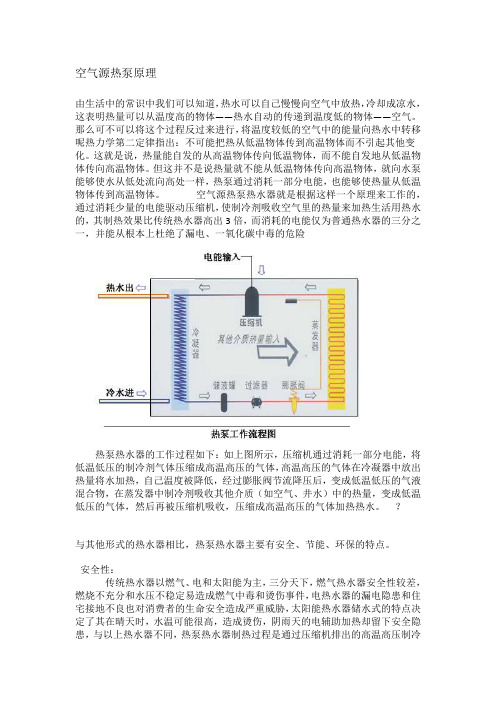
空气源热泵原理由生活中的常识中我们可以知道,热水可以自己慢慢向空气中放热,冷却成凉水,这表明热量可以从温度高的物体——热水自动的传递到温度低的物体——空气。
那么可不可以将这个过程反过来进行,将温度较低的空气中的能量向热水中转移呢热力学第二定律指出:不可能把热从低温物体传到高温物体而不引起其他变化。
这就是说,热量能自发的从高温物体传向低温物体,而不能自发地从低温物体传向高温物体。
但这并不是说热量就不能从低温物体传向高温物体,就向水泵能够使水从低处流向高处一样,热泵通过消耗一部分电能,也能够使热量从低温物体传到高温物体。
空气源热泵热水器就是根据这样一个原理来工作的,通过消耗少量的电能驱动压缩机,使制冷剂吸收空气里的热量来加热生活用热水的,其制热效果比传统热水器高出3倍,而消耗的电能仅为普通热水器的三分之一,并能从根本上杜绝了漏电、一氧化碳中毒的危险热泵热水器的工作过程如下:如上图所示,压缩机通过消耗一部分电能,将低温低压的制冷剂气体压缩成高温高压的气体,高温高压的气体在冷凝器中放出热量将水加热,自己温度被降低,经过膨胀阀节流降压后,变成低温低压的气液混合物,在蒸发器中制冷剂吸收其他介质(如空气、井水)中的热量,变成低温低压的气体,然后再被压缩机吸收,压缩成高温高压的气体加热热水。
?与其他形式的热水器相比,热泵热水器主要有安全、节能、环保的特点。
安全性:传统热水器以燃气、电和太阳能为主,三分天下,燃气热水器安全性较差,燃烧不充分和水压不稳定易造成燃气中毒和烫伤事件,电热水器的漏电隐患和住宅接地不良也对消费者的生命安全造成严重威胁,太阳能热水器储水式的特点决定了其在晴天时,水温可能很高,造成烫伤,阴雨天的电辅助加热却留下安全隐患,与以上热水器不同,热泵热水器制热过程是通过压缩机排出的高温高压制冷剂气体加热水罐中的水,电主要用于压缩机,制热后的气体通过外盘式的盘管与搪瓷水罐中的水交换热量,水电完全分离,这样,既不存在漏电隐患,省去了防漏电的烦恼,也避免了电加热管表面温度高,易结垢并影响加热效率的弊端,真正作到绝对安全。
- 1、下载文档前请自行甄别文档内容的完整性,平台不提供额外的编辑、内容补充、找答案等附加服务。
- 2、"仅部分预览"的文档,不可在线预览部分如存在完整性等问题,可反馈申请退款(可完整预览的文档不适用该条件!)。
- 3、如文档侵犯您的权益,请联系客服反馈,我们会尽快为您处理(人工客服工作时间:9:00-18:30)。
莱恩空气源热泵说明书
1、低温空气源热泵通过消耗部分电能获得2.5~3.4倍的供热量,冬季季节综合能源利用率23.0,一次能源利用率可达0.825~1.122,季节综合一次能源利用率为0.97,远高于电直接供暖和燃煤、燃气供暖的方式。
2、低温空气源热泵供暖时热量采自于空气,制冷时是将室内空气热量排放到室外空气中,不消耗任何水资源,不依赖水资源,不影响、不破坏水资源。
3、低温空气源热泵机组只需室外放置,例如:房顶、平台、地面等,只要是室外的任何地点都可以放置,不占用任何宝贵的土地资源。
4、冬季供暖与夏季供冷同时兼备,一机两用,机组利用率高,无需地下水源抽灌系统,无需十壤埋管系统,系统简单,工程耗材少,是典型的节材型技术。
5.高温出水,可以满足暖气片等未端设备的应用,更话合干老旧房层的供暖改造。