凯迪仕 K7 说明书
k7硬件说明书

K7密码一体机使用说明电气参数:工作电压:DC12V静态电流:<90mA工作频率:ID 125Khz,IC 13.56Mhz工作温度:-10℃--60℃工作湿度:5%--95%,无凝结卡片容量:K7-1为1350pcs;K7-3为2860pcs;K7-6为5840pcs输出负载:DC12V 2A,干节点信号外形尺寸:120*72*23mm进入编程模式:进入管理编程模式:按 # * 999999 # 键,999999为出厂默认管理密码,按*退出编程模式以下操作需在进入编程模式后进行:1、管理员密码修改按 1 XXXXXX #,XXXXXX为任意6位数的新密码。
2、添加用户用户代码手动设置:按 2 刷卡 XXXX #。
XXXX为4位数的用户代码。
用户代码自动设置:按 2 刷卡 #,用户代码顺序系统自动排序。
注意:代码范围K7-1型为0001-1350,K7-3型为0001-2860,K7-6型为0001-5840,注意:若重复用户代码,将覆盖先前相同用户代码的卡片。
3、删除用户删除所有的卡用户:按 3 0 0 0 0 #单张刷卡删除:按 3 读卡 #按用户代码删除: 按 3 XXXX #, XXXX为4位数的用户代码。
4、开门模式设置刷卡或密码开门模式:按4 0 #刷卡开门模式:按4 1 #(出厂默认)刷卡加密码开门模式:按 4 2 #5、开门时间设置按 5 XX #,XX为00—99的两位数字,设置00开门时间为0.5秒,出厂默认3秒。
6、安全模式设置关闭锁死功能:按 8 0 #(出厂默认)启动锁死功能:按 8 1 #,连续刷10次非法卡或刷有效卡后连续输入10次错误密码,系统锁死5分钟。
7、恢复出厂值初始化出厂设置:按 3 9 9 9 9 #,注意:系统编程密码恢复为999999,所有卡将删除,不可恢复,请妥善用此功能。
8、启用或修改开门密码本项操作无需进入编程模式,门禁机在正常状态下,按 #后刷用户卡,按XXXXXX # ****** #, XXXXXX为旧密码,出厂默认为123456;******为6位数的新密码,新密码不能为123456。
Kwikset Kevo Smart Lock套装安装指南说明书

61064 / 01 ArrayGuía de instalación y usuario3 4Instale el ensamble exteriorInstale el ensamble interior¿Cuál es el diámetro del orifi cio en la puerta?Retire la tapa interior y el paquete de baterías del ensamble interior.Conecte el cable más delgado.Conecte los cables correctamente y instale el ensamble interior.Conecte el cable más grueso.Instale el ensamble exterior y la placa de montaje.¿Cuál es el espesor de la puerta?AA BD C CBFEF2-1/8"54 mm1-1/2"38 mmoEl diámetro es 54 mm (2-1/8").El diámetro es 38 mm (1-1/2").Se requiere “F” para la instalación.Instale “F” en “E”.“F” no se necesita para la instalación.Descarta “F”.abcLMLNCompruebe que la perillaesté en la posición vertical.Retire la tapainterior.Retire elpaquete debaterías.Todavía no instalelas baterías.LPRECAUCIÓN: Manipulelos cables con cuidadopara evitar dañarlos. No tirede ellos ni utilice la fuerza.Asegúrese de que la conexiónsea firme.S (2x)a b cd eTuck cable hereInserte el cable aquíInsérez le câble iciExtienda el cable másgrueso contra elalojamiento interior.Presione el eje de la perilla en lapaleta de torsión.Evite pinzar el exceso de cabledelgado jalándolo lejos de la paletade torsión.Nota : La perilla de giro nopuede girar suavementehasta que después de laetapa 5.paleta detorsióneje de laperillaExtienda el cable más delgadoalrededor de la parte externa delconector cuadrado pertenecienteal cable más grueso.Pase el conector del cablemás delgado por detrás dela placa base (como seindica en la etiqueta delensamble interior).L Asegúrese de que la conexiónsea firme.EKKLQ/R (2x)GabcdeQ/RInserte la llave para probar el pestillo.Si el pestillo no se extiende o retrae consuavidad, ajuste los tornillos (Q/R).Retire la llave cuando haya terminado ycompruebe que el perno de retenciónesté extendido por completo.Los cables van pordebajo del pestillo.Encuentre la placa de montaje(K). Nota: La placa puede estarsituado en la parte posteriordel ensamble interior (L).Conecte loscables a travésdel orificiocentral y luegoempújelos por elorificio lateral.Mantenga paralelo alborde de la puertaAjuste los tornillosen forma uniformeorificiocentralorificiolateralQRoLa puerta es 35 mm (1-3/8")de espesor.La puerta es 44 mm (1-3/4")de espesor.Utilice los tornillos de plata más cortos.Utilice los tornillos de oro más largos.1-3/8"35 mm1-3/4"44 mmFunciones avanzadas©2014 Kwikset CorporationGuía de referenciaSensor de interior-exteriorLa cerradura Kevo cuenta con un sensor que le comunica si su dispositivo se encuentra dentro o fuera de su hogar para ayudar a prevenir que usuarios no autorizados abran la puerta mientras el dispositivo se encuentre en el interior.A partir de la versión de software 1.2.3., cada dispositivo de su sistema Kevo se calibrará automáticamente para habilitar este sensor. Para obtener más información sobre la calibración, consulte /kevo/support.Registro históricoPuede ver el historial de actividades de la cerradura a través de la aplicación Kevo o el portal web: .Notifi cacionesLa aplicación Kevo puede enviar notifi caciones cuando la puerta esté abierta y cerrada a través de los titulares de las llaveselectrónicas. Puede optar por recibir las notifi caciones predeterminadas del sistema o confi gurar las notifi caciones a medida paracontrolar a un usuario o período de tiempo determinado.Código de acceso de la aplicación KevoKevo presenta un código de acceso opcional para mayor seguridad que usted puede habilitar en el interior de la aplicación para usarlo encombinación con la contraseña de la aplicación. Para habilitar el código de acceso, debe ingresarlo cada vez que ingresa a la aplicación. Su función es proteger la cuenta Kevo de cambios no autorizados cuando su teléfono esté desbloqueado.Dispositivos compatibles con KevoTeléfonos inteligentes y dispositivos inteligentesUn teléfono inteligente (una tableta o un dispositivo móvile conectado a Internet) compatible con Kevo debe tener Bluetooth Smart Ready/ Bluetooth 4.0, y se debe instalar la aplicación Kevo específi ca del dispositivo. Averigüe si su dispositivo es compatible en /kevo/devices.Llavero transmisor KevoUn llavero transmisor es un dispositivo Bluetooth que proporciona la misma comodidad de tocar para abrir que un teléfono inteligente.Puede comprar llaveros transmisores adicionales según sea necesario. Puede registrar un máximo de ocho llaveros transmisores en una sola cerradura Kevo. Un solo llavero transmisor puede registrarse en 25 cerraduras Kevo.Nota: Puede elegir usar solamente llaveros transmisores Kevo,solamente dispositivos inteligentes o una combinación de ambos en su sistema Kevo.Llave estándarSiempre tenga acceso a la llave estándar de su cerradura.¿Necesita ayuda?1-800-327-56251-800-327-56251800 623 1180800 736 776/kevo/supportSi tiene preguntas, nuestro equipo de soporte Kevo altamente capac-itado pueden brindarle la ayuda que usted necesita:。
CK SWITCHES KT Series 螺纹螺帽锐化按键开关说明书

Dimensions are shown: mmSpecifications and dimensions subject to changeT a c t i l e S w i t c h esOrientation and Mounting Style SM Top Gullwing JM Top J Bend ****SAM Right angleSA1M Right angle with front solder padSA2M Right angle with front solder pad and pick & place tab SA3MRight angle with pick & place tabActuatorB0* Soft, flush B1* Soft, 0,64 mm B2* Soft, 2,24 mm P2** Hard, 2,36 mm P3** Hard, 1,12 mm P4** Hard, 3,96 mmS1*** ø0,1” for Press Fit Caps S2*** ø0,14” for Snap Fit Caps (with anti-rotation)3Features/Benefits• Full SMT side-actuated tact switch• SMT top-actuated tact switch with G or J terminations • High shear force with extended bracket • Easy to pick & place with top plate tab • Rubber or hard plastic actuator • Press fit or snap fit caps• RoHS compliant and compatibleTypical Applications • Telecommunications • Computer products • Instrumentation • Power supplySpecificationCONTACT ARRANGEMENT: SPST, N.O.TERMINALS: SMT terminationElectricalCONTACT RATING: 1.0 VA max. @ 32 V AC or DC max.ELECTRICAL & MECHANICAL LIFE: 100,000 make-and-break cycles at full load.DIELECTRIC STRENGTH: 250 Vrms min. @ sea level.CONTACT RESISTANCE: Below 50 mΩ typ. initial @ 2-4 V DC, 100 mA.INSULATION RESISTANCE: 109 Ω min.EnvironmentalOPERATING TEMPERATURES: A g version: -40˚C to 90˚CA u version: -40˚C to 125˚C ProcessSOLDERABILITY: Per MIL-STD-202F method 208D, or E IA RS-186E method 9 (1 hour steam aging).DEGREE OF PROTECTION: IP57; protection against harmful dust deposits, full-scale voltage protection.PackagingSwitches supplied in anti-static tape and reels per EIA 481-2. Tape and cover strip are conductive for use near statically sensitive components.NOTE : Specifications listed above are for switches with standard options.For information on specific and custom switches, consult Customer Service Center.BUTTONTo order buttons in bulk* B0, B1 & B2 available with A, A1 & A3 mounting bracket only.** P2, P3, P4 actuators suitable with A1 & A2 mounting bracket only.*** S1 & S2 available with A1 & A2 mounting bracket only.**** JM available with BO, B1, B2, P2, P3, P4 without mounting bracket.Button Color 90 Black80 Ivory (natural)40 RedSpecifications and dimensions subject to change3,18. * B0, B1 & B2 available with A, A1 & A3 mounting bracket only.** P2, P3, P4 actuators suitable with A1 & A2 mounting bracket only.*** S1 & S2 available with A1 & A2 mounting bracket only.**** JM available with BO, B1, B2, P2, P3, P4 without mounting bracket.Specifications and dimensions subject to changeT a c t i l e S w i t c h e sSpecifications and dimensions subject to changeTactile SwitchesSA3M RIGHT ANGLE WITH PICK & PLACE TAB(.125)3,18(.067)1,71(.114)2,904,61PAD LAYOUTSAM & SA3M MOUNTING BRACKETPAD LAYOUTSA1M & SA2M MOUNTING BRACKET24SCHEMATICDimensions are shown: mmSpecifications and dimensions subject to changeT a c t i l e S w i t c h esBUTTONTo order buttons in bulkMaterials: Nylon Finish: Gloss。
TOUCHLOCK K和KP系列指纹识别器说明书
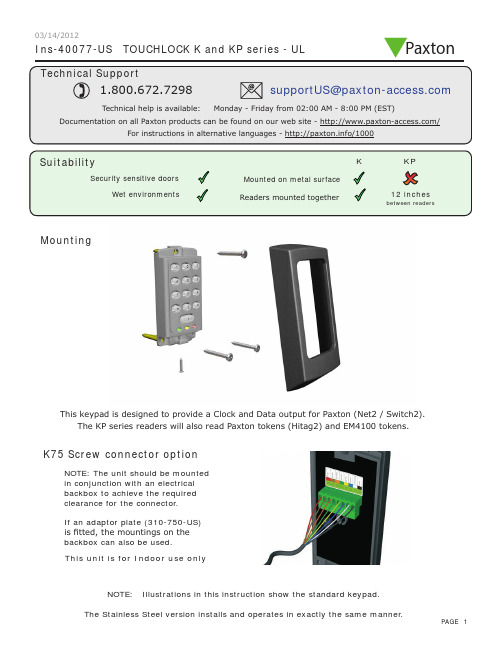
Ins-40077-US TOUCHLOCK K and KP series - ULMountingK75 Screw connector optionNOTE: The unit should be mounted in conjunction with an electrical backbox to achieve the required clearance for the connector .If an adaptor plate (310-750-US) is fitted, the mountings on the backbox can also be used.This keypad is designed to provide a Clock and Data output for Paxton (Net2 / Switch2).This unit is for Indoor use onlyNOTE: Illustrations in this instruction show the standard keypad.The KP series readers will also read Paxton tokens (Hitag2) and EM4100 tokens.Paxton03/14/2012Cable extensionsWiringNet2 control unitSwitch2 control unitStandard Unit - Drill a hole in the surface for the rear data cable. Secure the unit to the surface with three screws as per fitting diagram on page 1. 3 suitable screws and fixings are provided for fitting the unit to a wall. Ensure the data cable has free access at the rear .A choice of black and white covers are also provided. Hook the required cover over the top of the reader , press home at the bottom and secure with the single fixing screw.Screw Terminal Unit - The adapter (310-750-US) is mounted to a standard backbox using the fixing screws provided. The 75mm reader is then mounted onto the adapter using the fitting kit provided with the reader .KP series - When chosing a location for the reader , ensure that it is a least 12 inches from other readers. This will include readers mounted on the other side of the same wall as the radio signal will cause interference and reduce the read range. The reader should not be used on metal surfaces as the reflected signal will also reduce the range.Powering up the keypad will cause all the LEDs to come on. Once the control unit has been configured to accept keypad input (see controller instructions) pressing any key will make the keypad sound a bleep. Check the following FAQ section for assssistance if any problems are encountered.FCC ComplianceClass B digital devices.This equipment has been tested and found to comply with the limits for a Class B digital device, pursuant to Part 15 of theFCC Rules. These limits are designed to provide reasonable protection against harmful interference in a residential installation. This equipment generates, uses and can radiate radio frequency energy and, if not installed and used in accordance with the instructions, may cause harmful interference to radio communications. However , there is no guarantee that interference will not occur in a particular installation. If this equipment does cause harmful interference to radio or television reception, which can be determined by turning the equipment off and on, the user is encouraged to try to correct the interference by one or more of the following measures:-- Reorient or relocate the receiving antenna.-- Increase the separation between the equipment and receiver .-- Connect the equipment into an outlet on a circuit different from that to which the receiver is connected.-- Consult the dealer or an experienced radio/TV technician for help.Class A digital devices.This equipment has been tested and found to comply with the limits for a Class A digital device, pursuant to part 15 of the FCC Rules. These limits are designed to provide reasonable protection against harmful interference when the equipment is operated in a commercial environment. This equipment generates, uses, and can radiate radio energy and, if not installed and used in accordance with the instruction manual, may cause harmful interference to radio communications. Operation of this equipment in a residential area is likely to cause harmful interference in which case the user will be required to correct the interference at his own expense.This device complies with Part 15 of the FCC Rules. Operation is subject to the following two conditions:(1) this device may not cause harmful interference, and (2) this device must accept any interference received, including interference that may cause undesired operation. Changes or modifications not expressly approved by the party responsible for compliance could void the user's authority to operate the equipment.This unit is for Indoor use onlyFollowing the completed installation of this equipment, no further maintenance or testing is required.It is advisable to ensure that any third party backup power supplies or recovery procedures are checked regularly to ensure that the operation of the Paxton system is not compromised.Unit installation / test Maintenance/The use of any add-on, expansion, memory or other module manufactured or supplied by the manufacturer's representative will invalidate the CAN/ULC-S319 certification.For CAN/ULC-S319 installations, terminals, leads and wiring methods must comply with CSA, C22.1, Canadian electrical code, Part 1, safety standards for electrical installations.Product compliance and limitationsTo comply as a UL listed installation, the following conditions must apply:-Server based functions (Antipassback, Time and Attendance, etc) have not been evaluated by UL and cannot be used for UL 294 installations.The use of Wiegand readers and the configuration software has not been evaluated by 'UL' Wiring: - Where an equivalent cable / wire is used it must be ' UL Listed ' All interconnecting devices must be UL Listed.Wiring methods shall be in accordance with the National Electrical Code (ANSI/NFPA70), local codes, and the authorities having jurisdiction.This device complies with Industry Canada licence-exempt RSS standard(s). Operation is subject to the following two conditions: (1) this device may not cause interference, and (2) this device must accept any interference, including interference that may cause undesired operation of the device.。
K7产品说明书
第一章 K7型GPS测量系统简介 (3)1.1 系统的特色、组成、性能指标及配置 (3)1.1.1 K7型GPS新特色 (3)1.1.2系统组成 (3)1.1.3 K7测量系统的主要技术参数 (3)1.1.4 测量系统的基本配置 (4)1.2 K7型GPS测量系统的硬件 (5)1.2.1 K7型GPS接收机 (5)1.2.2 电池及充电器 (6)1.3 K7型GPS测量系统软件组成 (7)1.4 K7型GPS接收机充电及电源装卸 (7)一、打开K7主机侧面的电池后盖(见图1-2); (7)二、将电池后盖打开后取出锂电池(见图1-3),然后用配套充电器充电。
(7)第二章 K7型GPS测量系统实测 (8)2.1 概述 (8)2.2系统作业模式 (9)2.2.1 静态相对定位模式 (9)一、作业方法: (9)二、定位精度: (9)三、作业要求: (9)四、适用范围: (9)五、作业范围: (9)2.2.2后差分动态相对定位模式 (9)一、作业方法: (9)二、技术指标: (9)三、应用范围: (10)2.3 GPS网的技术设计 (10)2.3.1 测量的精度标准 (10)2.3.2网的图形设计 (11)2. 环形网 (11)3. 星形网 (12)2.3.3基线长度 (13)2.3.4网的基准 (13)2.4 选点与埋石 (13)2.4.1选点 (13)2.4.2 埋石 (14)2.5 K7型GPS测量系统的野外作业 (14)2.5.1 制定观测计划 (14)一、确定工作量 (14)二、采用分区观测 (15)三、选择观测时段 (15)四、确定观测进程及调度 (15)2.5.2安置及启动仪器 (16)2.5.3如何量取天线高即仪器高 (16)2.5.4启动仪器 (17)2.6 K7型接收机使用注意事项 (17)GPS测量应遵循《国家标准GPS测量规范》布网、施测、检核、计算。
(17)第三章K7型GPS测量系统文件及操作 (17)3.1 K7型文件系统简介与文件界面 (18)3.1.1 初始界面 (18)3.1.2 系统界面 (19)3.2 K7型文件系统野外数据采集 (23)3.2.1智能模式采集 (23)一、数据的采集: (23)二、给记录的数据取一个文件名: (24)三、退出数据记录: (25)3.2.2人工模式采集 (25)一、数据的采集: (25)二、给记录的数据取一个文件名: (25)三、退出数据记录: (25)3.2.3节电模式采集 (26)一、数据的采集: (26)第四章 K7内业数据传输 (27)4.1数据传输软件简介和界面 (27)4.1.1 菜单项 (27)四、查看菜单 (29)4.1.2 工具栏 (30)4.1.2 状态栏 (31)4.1.3 程序视窗 (31)4.2如何进行数据传输 (32)四、数据传输 (33)五、断开连接 (33)4.3.2检测注册码 (34)4.3.3设置功能 (35)第五章常见问题及解决方法 (35)第六章 K7后处理差分系统实测 (36)6.1.1 初始界面 (36)6.1.2 后差分野外作业步骤 (37)第七章如何升级主机软件 (39)附录A 有关专业术语注释 (41)附录B 年积日计算表 (43)附录C 联系方式 (45)附录D 全国销售及服务网络列表 (46)第一章 K7型GPS测量系统简介1.1 系统的特色、组成、性能指标及配置1.1.1 K7型GPS新特色K7智能一体化GPS接收机现已问世。
营销管理-浙江XX仕智能锁产品销售手册(DOC 8页)

凯迪仕智能锁产品销售手册一、智能锁市场现状随着时代的发展,人们对生活品质的追求越来越高。
传统机械锁,结构简单,容易重码,安全性差。
且携带不便,使用烦琐。
近年来不断涌现的各种密码锁、磁卡锁、感应卡锁、指纹锁等智能锁具,已拥有相当规模的市场容量。
在安全、方便、智能等各方面有绝对优势的智能锁必将逐渐替代机械锁,这已是不可否认的事实。
来自资料搜索网() 海量资料下载目前国内的智能锁市场,经过多年的发展,已开始进入成长期。
去年国内已有过三百个新建房地产楼盘预装智能锁,智能锁已成为中高端楼盘必需卖点。
受此带动,民用零售市场也已启动,如深圳安防市场,超过30%的店铺有智能锁出售,各大建材市场,智能锁已是随处可见。
2009年智能锁中国市场总销量达五十亿,比上年增长130%。
但市场的普及率还是很低,相比国际发达国家,如韩国的智能锁普及率已在68%以上。
预计未来几年将是中国智能锁市场高速发展期,十年内市场容量必突破千亿大关。
在温州,市场上智能锁也已随处可见。
都市花苑新田园等楼盘已率先预装智能锁。
而去年市区开盘的十来个楼盘,大部分都准备安装智能锁,如绿城广场、香缇半岛、京都城等。
温州人消费意识超前,经济实力强,智能锁潜力巨大。
二、产品知识1、指纹锁指纹锁是一种以人体指纹为识别载体和手段的智能锁具,它是计算机信息技术、电子技术、机械技术和现代五金工艺的完美结晶。
指纹锁一般由电子识别与控制、机械联动系统两部分组成。
指纹的唯一性和不可复制性决定了指纹锁是目前所有锁具中最为安全的锁种。
2、关于半导体电容式指纹模块的介绍(1)从光学传感器到电容传感器——指纹采集技术的演进指纹传感器是实现指纹自动采集的关键器件。
最早的指纹识别技术,是以光学传感器为基础的光学识别系统,识别范围仅限于皮肤的表层,通常把它叫做第一代指纹识别技术;而采用了电容传感器技术的第二代指纹识别系统实现了识别范围从表皮到真皮的转换,从而大大提高了识别的准确率和系统的安全性。
KEMPPI K7 FastMig X Intelligent 产品说明书

#stage-page-metaproperties-ffe1fc1aa015e09df2fef3fbadb00c94#02012023KEMPPI K7 WELDING EQUIPMENTFastMig X IntelligentINTELLIGENT WELDING FOR THE DIVERSE NEEDS OFMULTI-MATERIAL WORKSHOPS2.01.2023FastMig X IntelligentHIGH-CLASS MULTI-PROCESS SOLUTION FORDIVERSE DEMANDING WELDING APPLICATIONSThe Wise software features built into the FastMig X Intelligent setup cover the diverse needs of the most demanding welding tasks. Typical applications include, for example,stainless steel process equipment, boats' and ships' hulls built out of aluminum,and power plant pressure vessels made under strict supervision and obligation to produce detailed quality documentation.The setup is flexible enough to adapt to fast-changing needs and capable enough to meet the ever increasing quality requirements.See intelligent welding at its finest. Learn more by visiting the KEMPPI FASTMIG X FAMILY SITE.KEY APPLICATIONSALUMINUM BOATS PRODUCTION LINES02012023FastMig X Intelligent3402012023BENEFITSFULL RANGE OF OPPORTUNITIES FOR INTELLIGENTWELDINGKemppi FastMig X setup for diverse welding is designed to give superior weldingquality and performance with limitless flexibility in specialized tasks andmaterials. Meeting the diverse needs of any metal fabrication workshop hasnever been this easy: look no further for the perfect MIG/MAG weldingequipment for a wide range of applications, from demanding manual welding toefficient mechanized welding.THE BEST SOLUTION OUT THEREWe have designed the perfect setup for specialized tasks in a variety of weldingconditions. Select from various optional features and modify the FastMig Xsystem to perform precise tasks according to your needs. Thanks to optimizedwelding properties for sheet metal and plates, all positions and materials, mixedgases and CO2the setup meets all productivity and quality requirements. Thissetup will always fulfill your ambitions in welding.MATCHING HIGH PRODUCT QUALITY WITH SUPERIORSERVICEFastMig X is fully compatible with the world's most comprehensive weldingmanagement software, WeldEye. Among other things, it monitors compliance tothe WPS, ensures that welders have appropriate qualifications, and collectsquality documentation.The Kemppi worldwide service network also ensuresimmediate support and consultation. Weld more, produce more, and profit morewith the FastMig X.WELD FASTER, REACH FURTHERMulti-process welding solutions are essential for multi-material workshops. Thissetup, specifically engineered to offer diverse welding options, includes anintelligent collection of device and software component choices. Weld even asmuch as 30 % faster, reach up to distances of 30 m, and benefit from 25%lower heat input. Choose FastMig X for high quality welding with an optimizedproduction flow.02012023FastMig X Intelligent5WHAT'S IN THE SETUP- EQUIPMENTFastMig X 450 Power source Provides 450 A with 60% duty cycle. Suitable forgenerator use.WFX 300 AMC Wire feederFor welding high-strength steels and aluminum with Ø 200/300 mm wire spools. Strong double-skin plastic casing with a reliable DuraTorque wire feed mechanism. Built-in arc voltage measurement.Compatible with the ARC Mobile Control app.Cool X Cooling unitCool X cooling unit for liquid-cooled setups is the ultimate choice providing 1 kW of cooling power with3 liters of cooling liquid.ARC Mobile ControlFor the first time in welding history, you can now control and monitor your welding machine wirelessly via a smartphone or tablet computer. Download theapp from Google Play.6FastMig X Intelligent02012023WHAT'S IN THE SETUP - SOFTWAREWiseFusionA welding function that ensures consistent weld quality in all positions by automatically regulating arc length. Creates and maintains an optimal short-circuit characteristic in pulsed MIG/MAG and spray-arc welding.WisePenetrationA welding function for ensured penetration in synergic MIG/MAG welding. Delivers constant power to the weld pool regardless of changes in welding gun orientation or distance between the welding gunand work piece.WiseThin+Optimized short arc process suitable for welding sheet metals and thicker plates in position welding,even in case of wider gaps and gap variations.Produces a spatterless arc with precise digitalcontrol.MatchLogMatchLog includes Minilog and MatchChannel activation in WFX feeders (Minilog can be used only with MXF feeders). MatchChannel allows changing of the memory channel during welding and Minilog enables to change welding power in the samememory channel.02012023FastMig X Intelligent 7ALTERNATIVE - EQUIPMENT AND SOFTWAREFastMig X 350 Power sourceProvides 350 A with 80% duty cycle. Suitable forgenerator use.FastMig X 350 MV Power sourceProvides 350 A with 80% duty cycle. Multi-voltage power source that connects to 220 V - 230 V and 380 V - 440 V (+/-10 V) 3-phase supply voltages.Suitable for generator use.WFX 200 AMC Wire feederFor welding high-strength steels and aluminum with Ø 200 mm wire spools. Strong double-skin plastic casing with a reliable DuraTorque wire feed mechanism. Built-in arc voltage measurement.Compatible with the ARC Mobile Control app.8FastMig X Intelligent 02012023FastMig X 450 Power sourceProduct code6103450Connection voltage 3~ 50/60 Hz400 V, (-15…+20%)Fuse (delayed)35AMinimum generator power35 kVAOutput 60% ED450 AOutput 100% ED350 AOpen circuit voltage MMA U0 = 70-98 VUav = 50 VOpen circuit voltage MIG/MAG U0 = 80 - 98 VOperating temperature range-20 ... +40 °CExternal dimensions LxWxH590 × 230 × 430 mmDegree of protection IP23SStandards IEC 60974-1, IEC 60974-5, IEC 60974-10WFX 300 AMC Wire feederProduct code6103533Output440 AOutput 60% ED520 AWire feed mechanism DuraTorqueGun connection EuroFiller wire sizes (Ss)0.6 - 1.6 mmFiller wire sizes (Al)0.8 - 2.4 mmFiller wire sizes (Fe)0.6 - 1.6 mmFiller wire sizes (Cored wire)0.8 - 2.0 mmWire feed speed 1 - 25 m/minSoftware WiseFusionWisePenetrationWiseThin+MatchLogSteel Pack (12 pcs)Steel Pack for Wise thin+ (8 pcs)Stainless Pack (12 pcs)Aluminum Pack (12 pcs)Operating temperature range-20 ... +40 °CExternal dimensions LxWxH625 × 243 × 476 mmDegree of protection IP23SStandards IEC 60974-5Wire spool weight, max.20 kgWeight (empty)12.5 kgWire spool diameter, max.300 mm02012023FastMig X Intelligent9Cool X Cooling unitProduct code6068200Cooling liquid - 10 liter can - SP9810765Operating voltage (safety voltage)400 V -15 …+20 %Maximum pressure0.4 MpaExternal dimensions LxWxH570 x 230 x 280 mmWeight (no accessories)11 kgDegree of protection IP23STank volume~3 LEMC class ACooling power 1 kWStorage temperature range-40 …+60 °COperating temperature-20 …+40 °C10FastMig X Intelligent02012023Kemppi is the design leader of the arc welding industry. We are committed to boosting the quality and productivity of welding by continuous development of the welding arc and by working for greener and more equal world. Kemppi supplies sustainable products, digital solutions, and services for professionals from industrial welding companies to single contractors. The usability and reliability of our products is our guiding principle. We operate with a highly skilled partner network covering over 70 countries to make its expertise locally available. Headquartered in Lahti, Finland, Kemppi employs close to 800 professionals in 16 countries and has a revenue of 178 MEUR.。
CK SWITCHES 螺旋梯类电子开关说明书

Specifications and dimensions subject to change Tactile SwitchesElectricalMAXIMUM POWE R: 0.5 VA MAXIMUM VOLTAGE: 32 VDC MINIMUM VOLTAGE: 20 mV MAXIMUM CURRENT DC: 50 mA MINIMUM CURRENT DC: 1 mA DIELECTRIC STRENGTH: ≥ 250 Vrms (1mn)CONTACT RESISTANCE: ≤ 150 mΩINSULATION RESISTANCE:≥ 50 MΩBOUNCE TIME: ≤ 6 msEnvironmentalOPERATING TEMPERATURE: -40˚C to 85˚CSTORAGE TEMPERATURE: -55˚C (10 days) +85˚C (4 days)ProcessSOLDERING: This component is suited to the following methods:– Lead free reflow soldering process in accordance with IEC61760-1.PackagingIn reels of 5,000 pieces.Dimensions of reels according to EIA 481BExternal diameter 180 mmNOTE: Specifications listed above are for switches with standard options.For information on specific and custom switches, consult Customer Service Center. Features• 3.0 x 2.6 mm footprint• Smallest thickness with integratedactuator• Extended life cycles• IP68• Ultra low current capabilitiesTypical Applications• M obile Phones•H earing Aids•M P3 accessories•B luetooth Headset•Automotive keyless entry system•S moke and CO detectors•E-readers•H ome automation remote controlsSpecificationFUNCTION: momentary action, normally openCONTACT ARRANGEMENT: 1 make contact = SPST, N.O.TERMINALS: J lead type for SMTMechanicalTRAVEL (mm): 0.15 ± 0.1Part Number DescriptionFor any part number different from those listed above, please consult your local representative.KMT0 SeriesNano-Miniature SMT Top ActuatedB–9Dimensions are shown: mm21 mar 18T a c t i l e S w i t c h e sKMT0 SeriesMinimum actuator diameter is 1.0 mm. It is recommended to enlarge this diameter to a full flat surface covering the switch.ø 1 mini 1,22,62,33,61,42,43( 0,05 )2,60,3H3,4±0,1RECOMMENDED LAYOUTELECTRICAL DIAGRAM10,06TAPE & REELA ABB2±0,051,75±0,1ø 1±0,13,2±0,10,25±0,12,8±0,05+0,312-0,14±0,050,75±0,15,5±0,05+0,1ø 1,5 03,6±0,11,4DE-REELING DIRECTIONOUT OF THE TAPE21 mar 18DesignationH ±0.07KMT011NGJLHS 0.63KMT021NGJLHS KMT031NGJLHS 0.65KMT071NGJLHS。
- 1、下载文档前请自行甄别文档内容的完整性,平台不提供额外的编辑、内容补充、找答案等附加服务。
- 2、"仅部分预览"的文档,不可在线预览部分如存在完整性等问题,可反馈申请退款(可完整预览的文档不适用该条件!)。
- 3、如文档侵犯您的权益,请联系客服反馈,我们会尽快为您处理(人工客服工作时间:9:00-18:30)。
删除用户密码
设置开门模式
语音设置
进入管理模式,按【1】进入到用户设置,再按 【7】进入到设置开门模式。 进入管理模式,按【2】进入到系统设置,再按 【3】进入到语音设置。 按【1】设置为语音模式,整个
6
如何使用您的智能锁
6.1 在常用 模式下 6.1.1 密码开锁
1、打开滑盖,键盘灯点亮。 (如滑盖已打开,系统处于静止状态,可用手 掌面触摸按键区唤醒按键) 触 摸 键 盘 区 2、输入已添加的密码,按【#】确认,语音 提示:“验证成功,已开门”。 推 或 拉 开 门 3、推或拉动手柄开锁。
6.6.3 内部反锁
长按“COLSE”键反锁,语音提示“已反锁”,室外除机械钥匙外,无法正常 开启,需室内或钥匙开门解除
2 .更换电池提示 当系统语音提示“电量过低,请更换 电池”时,需及时更换电池。
按【1】进入到单个删除。 输入要删除的2位用户编号,按【#】 确认或将要删除的指纹放在指纹识别 区直到“嘀”声响,语音提示:删除 成功。 按【2】进入到全部删除,语音提示: 删除成功。
外面板(含硅胶垫) 内面板(含硅胶垫) 锁体 安装配件包 用户手册 百洁布 合格证 产品质量保修卡 钥匙盒 电池包 侧扣板组件 开孔模板 固定板 用户卡片 无线模块
1 1 1 1 1 1 1 1 应急钥匙2把
外面板
室外 室内
1、打开滑盖,键盘灯点亮。
输入2位用户编号(编号范围:00 ~ 09),按 【#】确认。
一键锁定键 防猫眼开关
注意
安装说明使用图片仅供参考,产品以实物为准。 14
注意
1 .根据门的厚度选择不同规格的配件包。 2 .默认出厂配置的配件包适用60 - 90mm门厚,如果是其它规格的门请联系我们。
推拉手柄
推拉手柄
4.9
装上电池,盖上电池盒盖,堵上胶 塞孔,装上侧扣板组件之后智能锁 安装完 成。
触摸键盘区 卡片识别区
将外面板连接线及电机线插入内面 板相应的插座中, 在将内面板上的 方轴对准锁体上 的转动口插入, 内面板紧贴门内 面。
4.8
旋紧两颗固定螺丝。
注意
00~94为常用指纹,95 ~ 99为胁迫指纹(配置有无线模块时开锁后可输 出报警信号)。
添加用户卡片(选配功能)
1 .加入网络 2 .退出网络 进入管理模式,按【1】进入到用户设置,再按 【3】进入到添加用户卡片。
右内推
内面板 外面板
4.3
左内推
内面板
在外面板上装上连接螺管和固定螺 管,执手孔中放上压簧和方轴。
连接螺管
4.4
8
方轴插口 定向螺丝
压簧大头 朝向执手
防撬开关
系列
后缀数字 常用模式目录
密码………… 6 . 1 . 1 指纹………… 6 . 1 . 2
用户设置目录
1 .添加用户密码 2 .添加用户指纹 4 .删除用户密码 5 .删除用户指纹 7 .设置开门模式 9 .修改管理密码 1 .添加用户密码 2 .添加用户指纹 3 .添加用户卡片 4 .删除用户密码 5 .删除用户指纹 6 .删除用户卡片 7 .设置开门模式 9 .修改管理密码
5
4.2
旋紧锁体上的四颗固定螺丝。
如何设置您的智能锁
如何进入管理模式
用户设置
添加用户密码
尊敬的用户您好!感谢您使用本智能锁,在您安装使用本产品之前请仔细核对产品清单,阅读安装说 明,并按本安装说明安装产品,若因未按本安装说明安装,导致的直接或间接的产品问题,及其他危 害和损失,我公司概不承担任何责任。
将卡片靠近卡片识别区直到“嘀”声响,语音 提示:添加成功。
注意:
胶塞
侧扣板组件安 装好之后,请 测试一下开关 门是否顺畅。
6、最大用户卡片容量为100个,用户编号为00 ~ 99。(选配功能) 7、输入400 +【#】,可查询序列号,语音播报数字.
纸 张: 1 2 8 g铜版纸 双面 单 黑印 刷 工 艺:风 琴7折,折 后 尺寸1 2 5 * 2 6 5 m m
6.3 机械钥 匙 开启 6.3.1 机械锁芯 若出现忘记密码,电池电量耗尽或系统无法运作等紧急情况, 可使用备用机械钥匙开锁。
6.6
门锁定
6.6.1 外部锁定
当锁处于自动模式下,关门1.5S后,方舌打出,语音提示“已关门”
6.8
门锁定
6.11
应急供电方法
进入管理模式,按【1】进入到用户设置,再按 【4】进入到删除用户密码。
系统提供语音提示。 按【2】设置为静音模式,整个 系统无语音提示。(除报警音和 操作管理菜单外)
输入要删除的2位用户编号,按【#】 确认,语音提示:删除成功。
按【2】选择安全模式,密码+指纹 (密码+卡片或指纹+卡片)双重验证 开锁。
2 .当防猫眼开关拔至“绿”色档位置,表示已关闭 防猫眼开启功能,此时内手柄可自由活动,可正
进入管理模式方法
定向螺丝
9 10
钥匙拨片
固定螺管
将连接线穿过门上方的过线口。 外面板上的机械钥 匙拨片与方轴对准 锁体上的两个转动 口插入,使外面板 紧贴门外面。
注意
00~04为常用密码;05 ~ 08为临时密码,开锁一次后立即失效。 在安全模式下临时密码不能开锁。09为胁迫密码(配置有无线模块时开 锁后可输出报警信号)。
【#】键确认,再次输入新的管理密码,按 【#】确认,语音提示:设置成功。
6.13
1、打开电池盒盖,里面有个“0-1-2”的拔动开关. 2、当开关拔动至“0”档时,门锁处于静音状态. (除报警音和操作管理菜单外). 3、当开关拔动“1”或“2”时,所有的语音都开启, 设定的数字越大声音越响.
扩展功能(选配功能)
K7系列
1
详情见 第5项说明
管理密码
标配锁体
主锁舌
11 12 13
1 1 1 2 1 (选配功能) (选配功能)
螺丝 螺丝
注意:
根据门的厚度适度裁剪机械钥匙拨片,选 择适当长度的方轴和连接螺管、固定螺管。 螺丝 螺丝 螺丝 螺丝
注意:
防撬开关应贴紧门 面,否则一旦通电 会发出报警。
5.2
液晶显示菜单索引
注意
在安全模式下,不能进行全部删除的操作。
删除用户指纹
进入管理模式,按【1】进入到用户设置,再按 【5】进入到删除用户指纹。
修改管理密码
按【1】设置为中文模式,整个
6.1.2 指纹开锁
进入管理模式,按【1】进入到用户设置,再按 【9】进入到修改管理密码。 按【2】设置为英文模式,整个 输入新的管理密码(密码长度:6~12位),按 系统提示音为英文。
推 或 拉 开 门
6.4 自动/常开 模 式 6.9
音量调节
9
系统提示音为中文。
指 纹 识 别 区
1、打开滑盖,键盘灯点亮。 2、将手指(已添加的)以正确的方式放在 指纹采集器上,嘀声后语音提示:“验 证成功,已开门”。 3、推或拉动手柄开锁。 1、打开电池盒盖 , 有个A-M的拔动开关 2、“A”档表示自动模式:当关门后,方舌自 动打出锁门,门处于锁定状态 3、“M”档表示常开模式:当关门后,方舌不
添加用户指纹
螺丝
螺丝
进入管理模式,按【1】进入到用户设置,再按 【2】进入到添加用户指纹。 1 .添加用户密码 2 .添加用户指纹 4 .删除用户密码 5 .删除用户指纹 7 .设置开门模式 9 .修改管理密码
K7
密码………… 6 . 1 . 1
插舌
5
指纹………… 6 . 1 . 2 卡片………… 6 . 1 . 3
记录查询
系统查询
注意
安装完成后,请及时修改管理密码。
注意:
安装时主锁舌 不能打出。
(如滑盖已打开,系统处于静止状态,可用手 掌面触摸按键区唤醒按键) 2、先按【*】两次,再输入管理密码,按 【#】确认。 3、语音提示:“已进入管理模式”。
室外
输入6 ~ 12位开门密码,按【#】确认;再次输入 开门密码,按【#】确认,语音提示:设置成功。
推拉换向 3.2 请按门的开向选择螺丝安装在什么位置。
1
使用须知与产品图
2
底部示意图
机械钥匙口 应急电源接口
产品清单/安装爆炸图
3
每套锁具数量
1 1
安装前须知
3.1 安装前门向确认 本智能锁可以适用于左外拉、左内推、右外拉、右内推,四种开向的门。
左开门
室内 左内推
4
4.1
右开门
室内 右内推 室外 室内 左外拉 右外拉 室外
安装步骤
根据开孔模板在门上开好孔,将锁 体放入门框内。
注意
电池电量低于4 . 8V时,系统在每次成功开锁后,语音提示:“电量低, 请更换电池”。此时,请及时更换电池。 (请勿将不同型号、新旧电池混用。)
1、把钥匙插入锁孔转动,即可推或拉动门开锁。
按【2】进入到全部删除,语音提示: 删除成功。
语言设置
进入管理模式,按【2】进入到系统设置,再按 【4】进入到语言设置。
输入2位用户编号(编号范围:00~99),按 【#】确认。
11 12 1.电池盖( 1个) 2.内外面板固定螺丝( 1个) 3 .内面板组件( 1套) 4.压簧(2个) 5.方轴 (2根 ) 6.固定板螺丝( 4个) 7.固定板( 1个)
13 8.锁体( 1个) 9 .内外面板连接螺管( 1个) 10.外面板组件 (1套 ) 11 .胶塞(1个) 12 .后面板固定螺丝 13 .固定螺管( 4个) 14 .机械钥匙拔片(1个)
详情见 第5项说明
管理密码
14 15
右外拉
外面板 内面板 外面板
左外拉
内面板
4.5
将固定板紧贴门内面,用固定螺丝 旋紧。