PARKER派克接头基础教程
Parker软管培训资料派克液压胶管培训资料技术培训资料
公制 6
8
10 12 15 20 25 32 40 50
公称
规格
英制 3/16 1/4 5/16 13/32 1/2 5/8 7/8 1-1/8 1-3/格
划线规格-4=4/16=1/4 (英制)
压力-会导致软管爆破!
系统工作压力? 静压还是动压?最高冲击压力?压力交
20023(4SH, 4SN) 特定行业和质量机构的认证
软管试验方法的国际标准
ISO1402-液压静压力试验 ISO6803-液压脉冲寿命试验 ISO7233-耐负压试验 ISO1817-介质相容性试验 ISO4672-低温柔软性试验 ISO6945-耐磨性试验 ISO7326-耐臭氧试验 ISO8033-黏附力试验
软管的基本参数
基本参数: 内径,外径
额定工作压力,最低 爆破压力,压力脉冲 寿命
耐真空度 介质适应性 适应温度范围 最小弯曲半径
长度变化率 耐磨性 耐臭氧 高压绝缘型 容积膨胀率 低温柔软性 粘合强度
软管选择的基本条件
介质 尺寸规格 压力 温度 应用条件 管接头 可供性
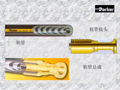
软管
软管接头 软管总成
软管的基本结构-钢丝编织软管
增强层
钢丝编织的夹角
-中位角- 54°44“
外层
内层
软管的基本结构-钢丝缠绕软管
钢丝缠绕的夹角 -中位角- 54°44“
软管的类别(按基本材料区分)
橡胶 软管(派克 HPD 产品 ) 热塑 软管(派克PARFLEX 和
POLYFLEX 产品)
781,782,792 热塑软管具有更优越的抗紫外线性能
软管接头- 是确保软管总成可靠工作的关键
2019年-PARKER接头基础-PPT精选文档

接头解析 接头螺纹-特征
牙顶和牙底:
接头解析 接头螺纹-特征
牙侧和牙型角:
接头解析 接头螺纹-特征 牙形角和锥度:
螺纹角度
锥度
接头解析 接头螺纹-特征
螺距:螺纹之间的距离
公制螺纹
接头解析 接头螺纹-特征
常用接头公制螺 纹螺距:1.0mm 、1.5mm、2.0mm
接头密封 形式
密封形式
• 24°扣咬型(切入型)
– 接头体、管套、螺母组成
– Ferulok,EO,EO-2,Compression,Compress-Align, Air Brake,Vibra-Lok,Poly-Tite
– 例:Ferulok, EO :卡套扣咬住(切入)管外壁,形 成密封。
接头密封 形式
接头解析 接头螺纹
平行螺纹(直螺纹):每个螺纹的外径都相等
平行
接头解析 接头螺纹
平行螺纹:
• 平行螺纹只能提供机 械支持力
• 通过其他方式来完成 密封例如: O-ring
接头解析 接头螺纹
锥形螺纹:螺纹的外径逐渐变小
锥形
接头解析 接头螺纹
锥形螺纹:
• 锥形螺纹有2方面作用:
机械支持力
密封 (通常需要其他辅
助密封剂)
• 英制螺纹 • 公制螺纹
螺纹型式
螺纹型式 英制螺纹
管螺纹: 管螺纹有锥形螺纹的特征 可提供机械支撑力和密封,通常还需使用密 封剂防止泄漏。
国家标准管螺纹和英国标准管螺纹的主 要区别在于牙形角 美国国家标准管螺纹:60度 英国标准管螺纹:55度
螺纹型式 英制螺纹
管螺纹(续): 多种形式管螺纹 干式密封:SAEJ476A和ANSI B1.20.3螺纹系列
Parker Hannifin 熟练培训指南说明书
Introduction ...................................................................................................................................................... E2Training MaterialsTextbooks/Course ComponentsIndustrial Hydraulic Technology ............................................................................................................. E3Hydraulic Maintenance Technology ........................................................................................................ E3Fluid Power Basics................................................................................................................................ E4Hydraulic Component Sizing ................................................................................................................. E4Filtration T echnology .............................................................................................................................. E5Hydraulic Pumps & Controls ................................................................................................................. E5Reference BooksDesign Engineers Handbook ................................................................................................................. E6Design of Electrohydraulic Systems for Industrial Motion Control .......................................................... E6Handbook of Electrohydraulic FormulaeE6An Engineering Analysis of the Pulse Width Modulation ........................................................................ E7Lexicon III ............................................................................................................................................. E7Computer SoftwareVCCM Design Environment ................................................................................................................... E8Video TrainingIndustrial Hydraulic Technology ............................................................................................................. E9Trainer StandsPortable Hydraulic Trainer .................................................................................................................... E10Lab Manuals........................................................................................................................................ E10Training ProgramsIndustrial Hydraulic Technology (IHT) .......................................................................................................... E11Hydraulic Component Sizing (HCS) ............................................................................................................. E11Hydraulic Pumps & Controls (HPC) ............................................................................................................. E12Hydraulic Maintenance Technology (HMT) ................................................................................................... E12Introduction to Electrohydraulics (EHD)....................................................................................................... E13Electrohydraulic Feedback Systems (EFS)................................................................................................. E13Cartridge Valve Systems (CVS) .................................................................................................................. E14Mobile Hydraulic T echnology (MHT) ............................................................................................................ E14ContentsIntroductionW elcome to Parker’s Involvement Training ProgramThe Training Department at Parker Hannifin was established in the early 1970’s and is recognized today as the industry leader in the development and presentation of training materials and programs. The Department’s charter states that the primary focus of activity shall include all phases of technical training for hydraulic and pneumatic industries. The charter also states that this would be non-commercial and involve state-of-the-art methodology.The Parker approach is one of involvement training. In its full scope, involvement training is one of active participation. This participation results in excellent student retention as well as providing a comfortable way of learning.Parker Catalog 0200 details the Training Department’s current offerings. This catalog is presented in two parts: Training Materials and Training Programs.Training MaterialsThe training materials section contains the following mixed media components:T extbooks/Course ComponentsReference BooksComputer SoftwareVideo T apesTrainer StandsMiscellaneousParker offers seven textbook and course combinations designed for both industrial and educational applications. T opics range from Basic Fluid Power to the specifics of Hydraulic and Pneumatic T echnology.All materials needed for a completeclassroom curriculum are available.T extbooks can be purchasedseparately or in combination with anynumber of additional coursecomponents including workbooks,instructor guide, multiple choiceexams, answer book, coursecertificates and, where appropriate,acetate transparencies and relevantreference books.Parker currently has six referencebooks available. Led by the DesignEngineer’s Handbook, all of thebooks are valuable tools for anyDesign Reference Library, whetherfor individual use or as anaccompaniment to the courses.Additionally, course subject mattercan be further enhanced with relatedcomputer software, video tapes andtrainer stands.Parker’s computer-aided softwarerepresents a strong commitment toadvanced training technology. TheBasic Pneumatic Training CD,featuring animation and video, is theleading pneumatic software in theindustrial market place.The video tape library contains fourcomplete modules for self-pacedone-on-one or group learningactivities. Both hydraulic andpneumatic training programs areavailable.Parker’s portable and full sizehydraulic, pneumatic, and pick-n-place trainer stands provide studentswith valuable hands-on experience.All training stands feature industrialgrade components and provide “RealWorld” applications of principles andcircuitry.Training ProgramsIn addition to training materials,Parker offers an on-going scheduleof classroom educational programs.The current list of classes includesten 3-5 day programs. Each class isled by a Parker certified instructor(s).Students are provided all necessarymaterials to attain course certification.Classes are held in strategiclocations across North America.See Catalog 0200 for a complete listof scheduled class locations.Course fees cover all class roomexpenses. Meals, transportationand lodging are not included.However, Parker will be glad to assistyou with lodging arrangements.Education and training arecontinuous processes. Parker’sInvolvement Training Program hasdoubled its offerings in the last threeyears alone. For the latestinformation on Training Materials orPrograms, please contact:Parker Hannifin CorporationTraining Department6035 Parkland Blvd.Cleveland, OH 44124-4141T el:(216) 896-2577Fax:(216) 514-6738E-mail:*****************.comThe following section gives abrief overview of the trainingmaterials and classes with ahydraulic or electrohydraulicemphasis.INDUSTRIAL HYDRAULIC TECHNOLOGY Industrial Hydraulic Technology2nd Edition, Bulletin 0232-B1ISBN 1-55769-025-1The Industrial Hydraulic Technology textbook is designed to introduce a student to hydraulics as it relates to industrial machinery. The 330-page text is organized into fifteen chapters which include:The Physical World of a MachineHydraulic Transmission of Force and Energy Petroleum Base Hydraulic Fluid Fire Resistant Hydraulic FluidOperation at the Suction Side of a Pump Hydraulic ActuatorsControl of Hydraulic EnergyCheck Valves, Accumulators and Cylinders Flow Control ValvesDirectional Control Valves Pressure Control ValvesPilot Operated Pressure Control Valves Hydraulic Pumps Hydraulic MotorsReservoirs, Coolers and Filters• Circuit illustrations are in six-color to aid the student in visualizing what is happening in a circuit.• Each chapter incorporates an exercise reviewing the lesson’s main points.HYDRAULIC MAINTENANCE TECHNOLOGYHydraulic Maintenance TechnologyBulletin 0240-B1ISBN 1-55769-019-7The Hydraulic Maintenance Technology textbook provides detailed maintenance and troubleshooting information for the user of industrial hydraulicequipment. The 148-page text contains ten chapters which include:Hydraulic Maintenance Introduction Hydraulic Graphic Symbology Power Unit Maintenance Pump MaintenancePressure Control Valve Maintenance Directional Control Valve MaintenanceFlow Control Valve and Check Valve Maintenance Cylinders, Motors and Accumulator Maintenance Leakage Elimination in Hydraulic Systems Fluids and Filter Maintenance• Contains troubleshooting charts with lists of common problems, causes and possible remedies.• This text is also a valuable reference for designers of industrial hydraulic equipmentHYDRAULIC COMPONENT SIZINGHydraulic Component SizingBulletin 0243-B1ISBN 1-55769-036-1The Hydraulic Component Sizing textbook provides an in-depth practical study of pumps, flow valves, pressure valves, directional valves, hydraulic motors, cylinders and accumulators and how total system performance is related to individual component characteristics. Filtration and overall heat generation is covered. The 244-page text is organized into eleven chapters which include:The Hydraulic System Cylinders and Motor The Electric MotorSources of Power - Pumps and Accumulators Check Valves and Directional Control Valves Unloading and Pressure Reducing Valves Reliefs, Counter Balances and Brake Valves Flow ControlsConditioning Systems - Reservoirs and Heat Exchangers Conditioning (Filters)Fluid Conductors• The text also includes a section of 17 assignments in the back of the book.FLUID POWER BASICSFluid Power BasicsBulletin 0239-B1ISBN 1-55769-029-4The Fluid Power Basics textbook is designed tointroduce students to hydraulics and pneumatics as it relates to industrial machinery. The 174-page text is organized into fifteen chapters which include:The Physical World of a Machine Force Transmission Through a FluidEnergy Transmission Using a Hydraulic System Control of Hydraulic EnergyEnergy Transmission Using a Pneumatic System Control of Pneumatic EnergyHydraulic Pumps and Compressors Check Valves, Cylinders and Motors Flow Control ValvesDirectional Control ValvesSimple Pressure Control ValvesPilot Operated Pressure Control Valves Hydraulic Fluid Conditioning Air PreparationFluid Conductors and Connectors• Each chapter incorporates an exercise reviewing the lesson’s main points.FILTRATION TECHNOLOGY Filtration TechnologyBulletin 0247-B1 (Softcover)ISBN 1-55769-037-5Bulletin 0250-B1 (Hardcover, Not Shown)ISBN 1-55769-033-2Filtration Technology is a must as a fundamental introduction to industrial filtration. The text covers topics such as fluids, contaminants, media selection and more. It is helpful to all personnel concerned with OSHA, safety and quality issues. This over 250-page text is organized into fourteen chapters which include:Introduction to Industrial Filtration Technology Fluids and Contaminants Contamination Dynamics Fluid and Filter AnalysisMultipass Filter and Media Selection Lubricant and Hydraulic FluidSpecifying Hydraulic and Lubricating Fluid Filters Water Absorption in Hydraulic and Lubricating Oils Filter and Media Selection for Single-pass Systems Fuel Filter/Water Separators Process Filtration SystemsCompressed Air and Gas Filtration Coolant FiltrationInstallation, Operation and MaintenanceHYDRAULIC PUMPS & CONTROLSHydraulic Pumps & ControlsBulletin 0238-B1ISBN 1-55769-031-6Hydraulic Pumps and Controls is a comprehensive text covering relevant pump topics from basic pump construction and operation to multiple controls,horsepower control and electronic pump controls. The book also contains sections on filtration andtroubleshooting. This 185-page, multi-colored text is organized into nine chapters which include:Pressure CompensationLoad Sensing Theory of Operation Input Power and Inlet Conditions Electrohydraulic Pump Control TroubleshootingRemote CompensationHorsepower (Torque) Limiting Control Hydraulic Filtration Energy ConservationDesign Engineers HandbookBulletin 0224-B1ISBN 1-55769-018-9Design of Electrohydraulic Systems for Industrial Motion Control, 2nd EditionBulletin 0246-B1ISBN 1-55769-032-4A hardcover 400-page text that covers all technical areas relative to motion control utilizing electrohydraulics.Technicians and designers, as well as mechanical,electrical and control engineers will find the text to be a useful tool. The text is also valuable for professors and students of motion control technology, because it provides the most current information available on this technology from a recognized expert.To satisfy the demand for a simple and practical treatment of hydraulics and pneumatics, including components and system connectors, Parker Hannifin Corporation has published a one volume, 320-page text entitled Design Engineers Handbook . The information contained in this text is organized to assist themachine designer and manufacturer, as well as service and maintenance personnel. It should prove to be equally valuable to the college and vocational school student preparing to enter any of these fields.• Each section includes design data, reference material, charts and diagrams.Handbook of Electrohydraulic Formulae, 2nd EditionBulletin 0242-B1ISBN 1-55769-034-0This handbook, written for technicians, engineers and designers, contains 25 chapters of commonly used formulas for the design of electrohydraulic motion control systems. All of the necessary information is centralized, making the design of electrohydraulic motion control systems easier. There is no other text available that offers this accessibility or breadth and depth of information.Lexicon IIIBulletin 0245An Engineering Analysis of the Pulse Width ModulationBulletin 0244This research report contains over 100 pages of detailed engineering information and data regarding the design and evaluation of the pulse width modulation (PWM)method of controlling hydraulic pump outlet pressure.PWM offers a very efficient way for making regulated pressure power units using fixed displacement pumps instead of the more expensive, conventional pressure compensated pumps.The report contains scores of graphical responses,representing hundreds of hours of labs and dataanalysis time. Concise Conclusions sections help the reader to quickly summarize the results and apply them immediately. A complete section is dedicated to Design Methodology so that users can learn the details needed to properly design and construct the power units.Also included is a background on motion control and constant pressure. In addition, authors discuss equipment and principles of operation as well as the method of investigation used.An Engineering Analysis of the Pulse Width Modulation is a must for anyone who uses, specifies, designs or builds hydraulic power units!The Lexicon III is a detailed bulletin of electrohydraulic terms and analogies. The book is laid out into two easy-to-use sections – a glossary of terms and a section on understanding electrohydraulic analogies. Many of the areas are represented by graphs and diagrams to further identify in detail the terms and analogies of electrohydraulics.The author conveniently includes a chart of the SI prefixes, the Handy Conversions Factors T able and a listing of the Greek Letters. This bulletin is a must-have for engineers, students and anyone interested in electrohydraulics.Training MaterialsComputer SoftwareVCCM Design EnvironmentBulletin 0298-P1The manual design of proportional and servo controlled systems requires many hours of computational work as well as much trial and error. Now, with the easy-to-use VCCM software, your can design state-of-the-art motion control systems at the cutting edge of technology!Simply tell VCCM the requirements of your job, and it will tell you the components you need for your design.All data passes through several menu driven screens which may carry explanations that are written in electrohydraulic engineering terms. VCCM does the number crunching for you, leaving you free toconcentrate on the more subjective and critical aspects of the design application. Anyone who has to size and select servo and/or proportional valves will benefit from the VCCM program.Requirements:• 386 CPU with DOS• 2 MB of Space on Hard Drive • SVGA monitor • Windows optionalIndustrial Hydraulic TechnologyBulletin 0299-T1The Industrial Hydraulic Technology course material is available utilizing an audiovisual tape training method.With all the training information stored on cassettetapes, the training sessions can be repeated as often as necessary, allowing each student to acquire the technical knowledge at his or her own pace.The various tapes focus on enabling the user to interpret and read schematics, obtain a working knowledge of components that make up hydraulic systems andadvance to trouble shooting techniques. (Refer to page 4 to see specific chapters covered).• Video tapes are available in Beta, VHS or PAL.• Individual chapters are also available.Includes:14 Video T apes 1 T extbook1 Instructor’s GuideTraining MaterialsVideo TrainingBulletin 0249EHD SupplementBulletin 0231Also available in Spanish!Bulletin 0229-B9 In order to aid the student in understanding hydrauliccomponents and systems operation, Parker hasdeveloped this comprehensive lab manual for the ModelHTV-00 Portable Hydraulic Trainer Stand. This manualcontains circuit problems and demonstrations designedfor use with the Parker trainer. These exercises areintended to supplement text material covered in theclassroom. References are made in this manual toParker textbook, Industrial Hydraulic T echnology (pageL3).Contains exercises using theElectrohydraulic Option Kit(P/N 875279) on the ParkerPortable Hydraulic TrainerStand.Portable Hydraulic TrainerBased on Parker’s long term experience indesigning, manufacturing and servicing fluidpowercomponents worldwide, the Portable HydraulicTrainer is designed to be a tool for learning hydraulictechnology principles and circuitry. It has beenengineered for ruggedness, portability and ease ofoperation. The unit is completely self-containedand operates on standard 115 Volt AC single phaseoutlet electrical power.The components on the trainer are all industrialgrade components used in industry every day. This“real world” approach allows the student to learnwhat those components look like as well as howthey operate.All necessary connections are made with hosesand quick disconnects. No tools are required toarrange circuits. Simply plug in the componentsneeded to arrange a circuit. In addition, all thehoses are stored are stored in a rack to avoidmisplacing “loose” components.For detailed information, request Bulletin 0203Training MaterialsTrainer Stands and Lab ManualsAlso available with the following options:• Electrohydraulic option provides an introduction toboth open loop and closed loop electrohydraulicsystems.• Pneumatic option transforms the hydraulic trainerinto a complete fluidpower training stand.。
Parker Hannifin 阀门 EtherCAT 接口安装手册说明书

Bulletin MSG11-5715-708/UK Installation ManualSupplement for Valves with EtherCA T Interface Parker HannifinManufacturing Germany GmbH & Co. KG Industrial Systems Division Europe Gutenbergstr. 3841564 Kaarst, GermanyTel.: (+49) 181 99 44 43 0E-mail:*********************Copyright © 2019, Parker Hannifin Corp.2MSG 11-5715-708 E therCA T U K N EU.indd 03.09.19Parker Hannifin CorporationInstallation Manual Valves with EtherCAT InterfaceInstallation Manual Valves with EtherCAT InterfaceMSG11-5715-708 E therCA T U K N EU.indd 03.09.193Parker Hannifin Corporation4MSG 11-5715-708 E therCA T U K N EU.indd 03.09.19Parker Hannifin CorporationInstallation ManualValves with EtherCAT InterfaceMSG 11-5715-708 E therCA T U K N EU.indd 03.09.195Parker Hannifin CorporationInstallation ManualValves with EtherCAT Interface6MSG 11-5715-708 E therCA T U K N EU.indd 03.09.19Parker Hannifin CorporationInstallation ManualValves with EtherCAT Interface1 General informationThis document is a supplement to the general valve manuals. Its sole purpose is to describe the opti-onal EtherCA T ® field bus interface.It is assumed the reader is already familiar with the EtherCA T ® field bus. Vast information about Ether-CA T ® and the CANopen Protocol is available at the below references and in the documents listed below. All parameters follow the common EtherCA T ® communications profile IEC 61158-x-12, CiA 301 (CA-Nopen Application layer and communication profile) and CiA 408 (CANopen Device profile fluid power technology proportional valves and hydrostatic transmissions). 1.1 Further documentation for the digital valvesThis manual is part of the complete documentation for digital valves existing of the following documents: • ProPxD parameter description • User manual valve Software: • ProPXD• ParkerDFPEtherCA T.xmlVisit /euro_hcd to download.1.2 ReferencesBelow organisations provide information about standards for EtherCAT ®, CANopen and the deviceprofile used.MSG 11-5715-708 E therCA T U K N EU.indd 03.09.197Parker Hannifin CorporationInstallation ManualValves with EtherCAT InterfaceDocuments of importance are listed below.1.2.1 EtherCAT ® FeldbusThe EtherCAT ® field bus interface provides a 100 Base full duplex real time Ethernet connection to the digital valves using standard EtherCA T ® frames according to IEEE 802.3.1.2.2 Object dictionary (CANopen over EtherCAT ®)1.2.3 Device profile1.2.4 Initiator of EtherCAT ®EtherCA T ® is a registered trademark and patented technology, licensed by Beckhoff Automation GmbH, Germany. EtherCAT ® was developed in 2003 by Beckhoff Automation GmbH and propagated as an open standard. To further develop the technology, the user association “EtherCA T ® Technology Group” (ETG) was established.Beckhoff’s product TwinCA T ® was used to verify the functionality of the EtherCA T ® interface. 2. Scope EtherCAT ® interface• Diagnostics (actual value feedback, temperature, fault, voltage, time of operation) • EtherCA T ®-status LEDs (Link/Active) • Valve status LED• Reduced Device State Machine (DSM) as per device profile CiA DSP-408 • Bus-cycle time down to 0.250 ms• 2 x EtherCAT ® – Connector M12x1 / 4-pin, d-coded (female) • Maximum operating temperature 85 °C8MSG 11-5715-708 E therCA T U K N EU.indd 03.09.19Parker Hannifin CorporationInstallation ManualValves with EtherCAT Interface3 Ethernet connectionThe EtherCA T ® vales are equipped with two M12x1 socket 4-pin (female), d-coded connectors, one EtherCA T ® IN and one EtherCAT ® OUT to implement the common bus topologies. Cables in variouslengths are available from Phoenix contact, Binder, etc.Location depends on case (Figure DFP).Connector (M12, 4pole, d-coded)MSG 11-5715-708 E therCA T U K N EU.indd 03.09.199Parker Hannifin CorporationInstallation ManualValves with EtherCAT Interface4 Function indication LEDsThe LEDs are located around the RS232 connector behind the screw cap at the top of the valve box (DFplus). Directly at the connector is the operation mode LED of the valve. On another PCB there are 3 LEDs for EtherCA T ®monitoring.10MSG 11-5715-708 E therCA T U K N EU.indd 03.09.19Parker Hannifin CorporationInstallation ManualValves with EtherCAT Interface5 Adding the device in TwinCATAny EtherCAT ® master should be able to communicate with the valve. The configuration is described for the TwinCA T ® System Manager from Beckhoff Automation GmbH. For offline configuration (applica-tion design), the slave configuration file ParkerHCDEtherCA TValves.xml should be available in the di-rectory C:\TwinCA T\Io\EtherCAT (TwinCA T ® 2) or C:\TwinCA T\3.1\Config\Io\EtherCAT (T winCAT ® 3). Online the devices can be scanned with the Scan Devices… menu command. The device has to be connected to the master. Select I/O Devices . Now press F5 or the magic wand button or the right mouse button and from the drop down Scan Devices …Follow the instructions of TwinCA T ® and when the devices are successfully configured, one should seesomething like the below:The valve can be operated by changing the values with the Set Value Dialog . Select tab Online , buttonWrite…These are the I/O’s to be connected to your control software. On how to accomplish this, see the T win-CA T® documentation or the documentation for your EtherCAT® master. The I/O’s are described by the objects 6040h , 6041h , 6300h , 6301h , 6380h and 6381h , see their descriptions further on.The device parameters are changed in the Set Value Dialog of the CoE-Online list. See below.6 WatchdogsThe EtherCA T® Slave Controllers (ESCs) support up to two internal watchdogs (WD), a Process Data watchdog used for monitoring process data accesses, and a Process Data Interface (PDI) watchdog monitoring Process Data Interface activity. They can be useful when implementing data intensive ap-plications.The timeout for both watchdogs can be configured individually, but they share a single Watchdog Divi-der (WD_DIV), register 0400h :0401h ). The watchdog timeout is calculated from the Watchdog Divider settings multiplied with the Watchdog Time settings for PDI (WD_PDI, register 0410h :0411h ) or Process Data (WD_PD, register 0420h :0421h ). Base time unit is 40 ns. The watchdog timeout jitters, the jitter depends on the Watchdog Divider settings. I.e., selecting smaller Watchdog Divider settings results in smaller jitter.The following equations are used for a quick estimation of the watchdog timeout (they are not exact in terms of nanoseconds):t WD_Div = (WD_DIV + 2) * 40 nst WD_PDI = [t WD_Div * WD_PDI ; t WD_Div * WD_PDI + t WD_Div ]t WD_PD = [t WD_Div * WD_PD ; t WD_Div * WD_PD + t WD_Div ]Registers used for watchdogs are described below.Timing for the watchdogs can be set in TwinCAT® as below. First select Box1 (Servo Valve DFplus), tab EtherCAT®, button Advanced Settings…The SyncManagers and other registers can be accessed in TwinCAT as below.6.1 Process Data WatchdogThe Process Data Watchdog is rewound (triggered) by a write access to a SyncManager buffer area, if the SyncManager is configured to generate a watchdog trigger signal (SyncManager Control register 0804h .6 for SyncManager 0, etc.). The watchdog trigger signal is generated after the buffer was com-pletely and successfully written (similar to the Interrupt Write of a SyncManager).The Process Data watchdog can be disabled by setting the Process Data Watchdog Time to 0.A timeout of the Process Data watchdog has the following consequences:• Watchdog Status register for Process Data (0440h .0) reflects the watchdog status.• The device is disabled (could be useful to implement user defined behaviour here).• The Watchdog Counter Process Data (0442h) is incremented.• A bus communication fault is generated.6.2 PDI WatchdogThe PDI watchdog is rewound (triggered) by any correct read or write access by the Process Data Interface. The PDI watchdog can be disabled by setting the PDI Watchdog Time to 0.A timeout of the PDI watchdog has the following consequences:• ESC DL Status register (0110h .1) reflects the watchdog status. This can be mapped to the ECA T interrupt to inform the EtherCAT® device.• The Watchdog Counter PDI (0443h) is incremented.7 CAN over EtherCAT® object dictionaryThe below is extensively described by the CAN in Automation (CiA®) e.V. in their documents CiA Draft Standard Proposal 301 (CANopen Application layer and communication profile) and CiA Draft Standard 408 (CANopen Device profile fluid power technology proportional valves and hydrostatic transmissions. Further the valve is equipped with an RS232 interface. Several parameters of this interface are mapped on EtherCAT® objects. For example U22, power supply voltage [1/10V] is mapped to object 2802h. U22 indicates that it is originally an RS232 parameter. See the ProPxD documentation for these RS232 parameters.8 Synchronisation manager (SM)Several synchronisation managers allow consistent and secure data exchange between the EtherCAT® master and the slave device. The SMs inform both sides about data exchange status.The SM settings in the object dictionary have read only access. These settings are read by the master at start up and are needed to configure the process data and mailbox communication.8.1 Object 1C00h: SM communication typeDetermines the direction and type of the communication for the specified SM channel.8.2 Object 1C12h: SM2 receive PDO assignment: SM3 transmit PDO assignment8.3 Object 1C13h9 Process data object (PDO) communicationThese objects define the parameters communicated over the real time communication channels of SM2 and SM3. The communication channels exist of 3 buffers so writing and reading can take place simul-taneous. Mailbox communication uses only one buffer so reading and writing takes place alternating.9.1 Process data object mapping (PDO mapping)The object 1600h represents the RxPDO mapping and the object 1A00h represents the TxPDO map-ping. Sub-index 00h contains the number of valid mapping entries within the mapping object. Sub-indeces 01h to 08h contain the references to the mapped application parameters. The application parameters are referenced by their index, sub-index and length. The length contains the length of the application parameter in bits. This may be used to verify the mapping.The pointer contains a combination of index, sub-index and length of the parameter to be used. It may only refer to parameters with a bit length of 10h.Remapping is not implemented. The objects are configured to be read only.9.2 Object 1600h: RxPDO mapping (CiA 301/408)The parameter no. of mapped application objects in PDO (1600h) sets the number of real-time appli-cation parameters to be received. The application parameters are mapped by combining its index, sub-index and length to a 32 bit number which is written to one of the index positions within the PDO object.The following three parameters from the object dictionary are mapped as process data parameters by default according to CiA 408:Device state machine (DSM) Control Word (6040h)Spool position setpoint value (6300h sub-index 01h)Pressure setpoint value (6380h sub-index 01h) (D*FP only)9.3 Object 1A00h: TxPDO mapping (CiA 301/408)The parameter Nr. of mapped application objects in PDO (1A00h) sets the number of real-time appli-cation parameters to be transmitted. The application parameters are mapped by combining its index, sub-index and length to a 32 bit number which is written to one of the index positions within the PDO object.The following three parameters from the object dictionary are mapped as process data parameters by default according to CiA 408:Device state machine (DSM) Status Word (6041h)Spool position actual value (6301h sub-index 01h)Pressure actual value (6381h sub-index 01h) (D*FP only)10 Device identification10.1 Object 1000h: device type (CiA 301)The LS 16 bit word (bits 15...0) describes the device profile number that is being used. 408 is the value for CiA408, the profile for hydraulic devices. The MS 16 bit word for additional information is not used.10.2 Object 1008h: M1 manufacturer device name (CiA 301)ProPXD parameter number M1 Manufacturer short text.10.3 Object 1009h: Manufacturer Hardware Version (CiA 301)Indicates the current hardware version of the device electronics.10.4 Object 100A h: manufacturer software version (CiA 301)Indicates the current software version of the device.10.5 Object 1018h: identity object (CiA 301)These parameters represent a unique identification for the device.The vendor ID assigns the device to a manufacturer and department. Assigned uniquely to manufac-Department HCD = 08hCompany Parker Hannifin = 000089hFurther identification by the ProPXD parameters M2, M1 and M4 in objects 6052h, 1008h and 6053h.10.6 Object 6052h: Device serial number (CiA 408)The unique serial number of the device.10.7 Object 6053h: M4 device description (CiA 408)ProPXD parameter number M4 date code.10.8 Object 6055h: Device model URL (CiA 408)The internet address where to find additional information about the device.10.9 Object 6057: Device vendor name (CiA 408)10.10 Object 605F h: Device capability (CiA 408)Contains information on the capabilities of a device.Value description:Module Information:See also object 6043h: Device control mode.11 Device controlThese objects represent the parameters used for device control.11.1 Device State Machine (DSM)Reduced Device State Machine as by device profile CiA DSP-408. The device state machine (DSM) describes the status of the device and the transitions between them. Any state represents a certain internal and external behaviour. Status changes are caused by the control word 6040h or external events (like switching on the supply voltage or device faults). The current device status is presented in the status word (6041h bits 0..3).The table below describes the states and the actions performed in them:The table below describes the transitions between the states:11.2 Object 6040h: Device control word PDO (CiA 408)Controls the device status.The lower 3 bits 0, 1, 2 represent the device control command. The 4th bit, bit 3, resets a fault.Bit 0: Disabled (D)Bit 1: Hold enable (H)Bit 2: Device mode active (DM)Bit 3: Reset fault (R)This parameter is present in the Outputs variables, see the TwinCAT view below. The button Write… presents the Set Value Dialog. For example write 7 to set the device to operational. The parameter is also present in the CoE – Online view. Changing it there has no use as it is kept to the value set in the list.Outputs11.3 Object 6041h: Device status word PDO (CiA 408)Indicates the device condition.The lower 4 bits 0, 1, 2, 3 show the actual state of the device state machine (DSM).Bit 0: Disabled (D)Bit 1: Hold enable (H)Bit 2: Device mode active (DM)Bit 3: Ready (R)Bit 4: Local control. Set when instead of the bus value a local control value is used as setpoint (bit 0 in object 604F h is set to 1 by user).Bit 15 Indicates the setting of an optional hardware disable switch which supersedes the EtherCA T® control.This value is present in the Inputs list and in the CoE – Online view.11.4 Object 6043h: Device control mode (CiA 408) (D*FP Only)The control mode is set with the parameter 6043h.At the current version the device can be run in the following control modes.See also object 605F h: Device capability.11.5 Object 604F h: Local (CiA 408)When set the local analogue setpoint value supersedes the EtherCA T® setpoint. Upon this Bit 4: Local control, in object 6041h is set.12 Setpoint valuesSet point, actual value, device control word and device status word are located in objects that are mapped on the input output structure as can be seen in the TwinCA T System Manager views.12.1 Object 6300: Valve position control closed loop setpoint (CiA 408)This object is present in the CoE – Online view and in the Outputs list. Change it in the Outputs list only as a change in CoE – Online is overwritten by the Outputs..12.2 Object 6301h: Valve Position Control Closed Loop Actual Value (CiA 408)This object is present in the CoE – Online view and in the Inputs list.12.3 Object 6380: Valve pressure control closed loop setpoint (CiA 408) (D*FP only)This object is present in the CoE – Online view and in the Outputs list. Change it in the Outputs list only as a change in CoE – Online is overwritten by the Outputs.12.4 Object 6381h: Valve pressure control closed loop actual value (CiA 408) (D*FP only)This object is present in the CoE – Online view and in the Inputs list.13.2 Object 1003h : Pre-defined error field (CiA 301)This object shall provide the errors that occurred on the (CANopen) device and were signalled via the emergency object (not implemented). In doing so it provides an error history.Parameter U24, Error codes + operating counter, is mapped on this object. Only the last 10 errors + minute counter in the additional information field. Value Definition:• The object entry at sub-index 00h shall contain the number of actual errors that are recorded in thearray starting at sub-index 01h . Note: If no error is present the value of sub-index 00h is 00h and a read access to sub-index 01h is responded with an SDO abort message (abort code: 0800 0000h ). • Every new error is stored at sub-index 01h ; older errors are moved to the next higher sub-index. • Writing 00h to sub-index 00h deletes the entire error history (empties the array). Other values than00 h are not allowed and lead to an abort message (error code: 0609 0030h ). Don’t use this option when the valve is enabled as the EEPROM erase routine blocks the regulator interrupt and the valve does not operate properly for a second.• The error numbers are of type UINT32 and are composed of a 16-bit error code and a 16-bit addi-tional error information field, which is manufacturer-specific. The error code is contained in the lo-wer 2 bytes (LSB) and the additional information is included in the upper 2 bytes (MSB).Fehler Codes: siehe das unten beschriebene Objekt 2000hY2 Error codes.Value descriptionIf a specific error occurs, the corresponding error group bit is set to 1 b . The generic error shall be set at any error situation. The bits are cleared automatically when their corresponding errors have gone.13 Error codesThe device internal errors are mapped on the CiA 301 defined object 1001h . The correct error informa-tion is provided by (RS232) parameter Y2 mapped on object 2000h . Error handling and acknowledge is provided by parameter J12 mapped on object 2001h . Emergency messages are not supported yet. 13.1 Object 1001h : Error Register (CiA 301)The (CANopen) device maps internal errors into this object.13.3 Object 2000h: Y2 Error CodesThese errors are also mapped on object 1001h, see table.Error CodesWhen errors occurred concurrently the addition of their error codes is shown. Each error code is valu-ed only once. Error bits, when not pending, can be reset by writing a 0 b to their location (don’t set a bit when the valve is enabled, this will disable the valve as if a real error occurred.Examples:Error code 0019h:overcurrent shutdown (code 0001h) + under voltage guard (code 0008h) + bus communication error (code 0010h)Error code 0028h:undervoltage guard (code 0008h) + SPI bus communication (code 0020h)13.4 Object 2001h: J12 Error handling/acknowledgeErrors, for which the corresponding bits are set in this object, are acknowledged automatically, when not pending.14.1.3 Object 2804h : J8 Supply voltage supervision [1/100 V]Used to set the under voltage limit in 1/100V . Use the object 1010hto store this value in non-volatile.14.1.4 Object 2805h : J9 Supply voltage min time in limit [ms]Used to set the time in milliseconds the supply voltage is allowed to drop below the supervision voltage without generating an error. Use the object 1010hto store this value in non-volatile.14.1.5 Object 2806h : U18 TemperatureGives the actual temperature of the PCB in °C.14.1.6 Object 2808h : U25 Temperature extremesMinimal and maximal temperature measured in °C.14 Monitoring14.1 Hardware Monitoring14.1.1 Object 2802h : U22 Power supply voltage [1/10 V] Gives the actual supply voltage in 1/10V , normally around 240.14.1.2 Object 2803h : U26 Maximal supply voltage and error countGives the maximal supply voltage measured and the number of under voltage dips registered.14.1.7 Object 280A: U23 Load current14.1.8 Object 280D h: U20 Operating time day counterTime in days the valve is operational and enabled. Can be changed by writing a value. Shows together with object 280E h the operating time.14.1.9 Object 280E h: U21 Operating time minute counterTime in minutes the valve is operational and enabled. Can be changed by writing a value. Shows toge-ther with object 280D the operating time.15 Storing / restoring parametersThe electronics of the device provides a non-volatile memory which allows storing parameters. The current values of all parameters declared as non-volatile (persistence = Y) can be stored in non-volatile memory on the device. Three storing / restoring operations are possible:• Parameters can be stored in non-volatile memory• Parameters are loaded during a power on cycle• Factory settings can be restoredDuring power on the user parameters stored in non-volatile memory are loaded in volatile memory to be worked with. The user can change parameters to adjust the behaviour of the device. After a power cycle these changes are gone unless they are stored in non-volatile. When messed up the factory settings have to be restored.15.1 Object 1010h: L2 Store parameters (CiA 301)Storing is performed when the signature 65766173h (“save”) is written to the parameter. The parameters are stored in user memory and loaded as working parameters each power cycle.15.2 Object 1011h: L1 Restore default parameters (CiA 301)The factory settings can be restored by writing the signature 64616F6C h (“load”) to the parameter.。
派克胶管总成安装使用指南
掘进机公司研究所派克胶管总成及油口接头安装使用指南一、概述派克的胶管总成是由派克的胶管及与其相匹配的胶管接头按严格要求扣压组成。
油口接头指通常所说的端口接头、接头座。
二、胶管及油口接头安装前的检查安装前必须对对胶管进行仔细的检查,必须检查所使用的胶管及其油口接头的型号、压力等级、长度及胶管两端的接头型式是否与图册所示胶管型号一致。
检查胶管是否清洁,是否堵塞,有无起泡,外覆盖层是否有脱层或有否其他可见的缺陷;胶管接头的O型圈是否损坏。
油口接头的ED密封圈是否损坏。
三、胶管及油口接头的安装时注意事项1、最小弯曲半径:以小于规定的最小弯曲半径安装胶管,会大大降低胶管的寿命.切忌在胶管接头处进行过度的弯曲;2、扭曲角度及方向:胶管的安装必须避免由于机器零件的的相对运动而发生胶管扭曲;3、胶管与油口接头的正确连接:一根胶管正确的安装状态要求胶管接头与油口接头连接后不会由于装配、使用等因素在胶管上产生扭曲或扭距;4、为了保证胶管的旋转螺母接头与相关的油口接头体之间无泄漏的密封,即在O型圈密封的地方。
必须按表1所示力矩拧紧胶管。
5、ED圈密封处,拧紧力矩注意:螺纹拧入前应使用液压油润滑;拧紧时不得使用加力杆。
切忌过量的拧紧会造成胶管接头泄露。
四、胶管及油口接头的检修1、一旦发现下列情况,都必须立即停车,并及时更换胶管:胶管外覆盖层发泡、变软、剥蚀或脱层;胶管硬化、热开裂或碳化;胶管或胶管接头泄露;胶管屈折被压扁或受到扭曲;2、如有下列情况,应进行拧紧,修理1PDF 文件使用 "pdfFactory Pro" 试用版本创建w 。
派克Parker流体连接件中国区产品手册 上

在线培训
除了传统的课堂培训,派克还提 供在线培训。这些培训包括:
• P-TAC: 派克在线培训和认 证项目可以使您成 为流体连接件产品 的专家。
• 安全学习: 3个20分钟的互动模 块能够帮助员工在进 行相关操作时,学习、理解并且 遵循安全操作的指引
派克培训中心可为您提供系列培 训课程,这些课程均由具有派克 资质认可的培训师授课,并且为 参加学生提供必要学习材料,并 颁发课程证书。
航空航天 环境控制 机电 过滤 流体与气体处理 液压 气动 过程控制 密封与屏蔽
流体连接件中国区产品手册
3400-CN
关于派克汉尼汾
派克汉尼汾是全球领先的运动控制技术及系统的多元化制造商,年销售额超过 100亿美元。我们为商用车辆、行走液压、工业液压和航空航天等行业提供了包 括流体处理、过滤、密封和屏蔽、环境控制、过程控制及航空航天等精准技术 解决方案,我们的产品应用于运动控制领域的各个市场。我们实施多元化、价 值驱动的发展战略,并且很好地定位于全世界每个角落的发展。派克汉尼汾在 美国纽约证券交易所上市代码是“PH”。
ห้องสมุดไป่ตู้
1
Parkrimp扣压设备操作简
单方便:
1. 在软管上标记出插入深 度并插管
2. 选择合适的模具和扣压
环,并将其放置到位
2
3. 将软管和接头放置到
位,按下油泵开关直至扣
压环底端紧靠支架平台。
完成后,打开阀门,将扣
好的总成取出
3
派克青岛工厂可生产多种编织管和缠绕管, 这些软管与派克Parkrimp扣压设备相配套, 为客户提供更经济、更可靠的软管总成。
在派克,我们相信,最好的软管,就是能确保您的工作正确 并正常进行的那个。因此,我们为您提供了全系列可供不同 应用的软管。
派克接头安全操作及保养规程
派克接头安全操作及保养规程派克接头是工业领域中常用的连接器件,其具有安全、可靠、高效的特点,但接头使用不当或保养不当都可能会导致安全事故发生。
为了确保使用安全,本文将介绍派克接头的安全操作及保养规程。
一、安全操作规程1. 严格遵守使用说明书使用说明书提供产品的概述、安装、使用、维护和维修方法,是使用派克接头的重要参考资料。
在使用派克接头前应认真阅读使用说明书,并按照说明书的要求进行操作,严格遵守操作规程。
2. 保持派克接头干净保持派克接头干净是使用接头的前提,可避免因灰尘、油污等杂质进入导致接头损坏或故障。
在清理派克接头时,应使用清洁剂,并保证清洁操作的安全性和正确性。
3. 避免接头过度弯曲过度弯曲会导致接头疲劳和永久性形变,进而影响接头的工作效果。
所以,在工作操作中,应避免过度弯曲接头,同时也要注意避免在接头附近出现大面积的弯曲或夹角超过20度的情况。
4. 确保紧固力度恰当在使用派克接头时,应确保紧固力度恰当。
过紧或过松都会影响接头的正常工作,因此,在安装、维护和保养派克接头时,必须遵循已有的标准,确保接头的紧固力度符合规范。
5. 避免接头磕碰在使用派克接头的过程中,应尽量避免接头磕碰,减少接头的损坏和变形风险。
如果接头误碰,应检查接头是否受损,并及时进行更换。
6. 妥善存放派克接头派克接头的存放需要重视,应存放在干燥、清洁、不受阳光直射、气温适宜和通风良好的位置。
存放时应保持接头处于原本装备中的状态,防止接头受损。
二、保养规程1. 定期检查派克接头派克接头使用一段时间后,需定期进行检查,发现或预防接头设备出现异常故障,影响接头使用寿命。
在检查派克接头时,应注意以下几点:•检查接头表面是否有过度磨损和裂纹等缺陷。
•检查接头的紧固螺栓是否松动或存在其他损坏现象。
•检查接头内部是否有过多油污现象。
2. 定期更换配件为了确保派克接头的正常使用寿命,应定期更换接头的配件,包括密封圈和螺纹连接器等。
更换时,必须选用和匹配原装配件。
parker EO2卡套式管接头的装配[教学]
案例三
要点一
总结词
要求高,需保证水质纯净
要点二
详细描述
某水处理厂在装配parker eo2卡套式管接头时,由于对水 质要求极高,需要保证管路系统的密封性和纯净度。首先 ,要选择优质的材料和管接头,确保管路系统的耐腐蚀性 和长期稳定性。其次,在装配过程中要严格控制环境和操 作卫生,避免杂质和污染物进入管路系统。最后,要定期 对管路系统进行清洗和消毒,确保水质的纯净度和安全性 。
案例二
总结词
高风险,需严格遵守安全规程
详细描述
某化工厂在装配parker eo2卡套式管接头时,由于涉 及易燃易爆和有毒介质,需要严格遵守安全规程。首 先,要选择符合安全标准的管接头和管路材料,确保 管路系统的可靠性和安全性。其次,在装配过程中要 遵循安全操作规程,穿戴防护用品,避免直接接触有 毒或腐蚀性介质。最后,要定期对管路系统进行检查 和维护,确保管接头的密封性能和安全性能。
检查卡套式管接头的安装情况,确保其紧固且无松动现 象。
检查卡套式管接头的旋转和移动部分,确保其顺畅无阻。
清洁与润滑
01
使用适当的清洁剂和润 滑剂,保持卡套式管接 头的清洁和润滑。
02
03
04
定期清洁卡套式管接头 的内部和外部,去除灰 尘和污垢。
在适当的位置加注润滑 剂,以减少摩擦和磨损。
注意润滑剂的选择和使 用量,避免过多或过少。
操作要点
在装配之前,应检查管接头和管道是否清洁干燥, 确保没有杂质和水分。
按照正确的顺序安装密封圈和卡套,确保卡套的 开口与密封圈的位置对应。
在装配过程中,应使用专用的卡套工具,按照规 定的力矩值拧紧管接头,确保密封效果良好。
常见问题及解决方案
派克软管接头密封形式讲解
软管接头的型式确定其实可以从外观、密封表面形式及螺纹形式来确定。
通过外观可以判断是直接头,还是弯接头等等,而各种接头的螺纹形式从外表看起来都比较类似,为正确分辨就需要用到螺距规或者卡尺等专业的测量工具。
今天,我们就针对密封形式来进行讲解,看如何先通过密封来确定接头的大概型式。
软管接头的密封形式:
螺纹
O型圈
配合角度或金属—金属连接
带O型圈及相关配合的角度
螺纹:外螺纹和内螺纹连接后其牙型之间的挤压可形成密封,典型的螺纹密封连接形式为锥螺纹密封。
O形圈:外螺纹接头上的O形圈挤压在相应的内螺纹配合面上形成了密封,在高压系统里通常采用这种密封型式。
配合角度或金属与金属硬密封:螺纹锁紧后,一定角度的金属斜面相互契合并紧密的挤压在一起产生形变后形成密封。
带O型圈的斜面:这种接头将金属斜面密封和O形圈密封两种方式结合在一起,当锁紧螺母时,密封面相互契合,并使O形圈在两者之间变形。
Parker软管培训资料,派克液压胶管培训资料,技术培训资料
02
Parker液压胶管介绍
液压胶管种类
按用途分类
Parker液压胶管可分为高压胶管、耐油胶管、耐酸碱胶管、空气胶管等,用 于满足不同领域的使用需求。
按结构分类
Parker液压胶管可分为单层胶管、双层胶管、三层胶管等,结构不同,其性 能也有所差异。
液压胶管材料
高压胶管
通常采用高强度聚酯纤维或钢 丝编织,内胶层为耐磨性优良
耐磨性能好
耐油、耐酸碱
液压胶管的内胶层具有优良的耐磨性能,可 以延长使用寿命。
根据使用需求,Parker液压胶管具有耐油、 耐酸碱等特性,可以适应不同的工作环境。
03
Parker技术培训
Parker产品使用技术
01
02
03
软管连接技术
介绍各种软管连接方式, 包括快插、卡套、螺丝连 接等,以及适用场景和使 用技巧。
Parker软管特点
高工作压力
派克软管可以承受高达10,000Psi的 工作压力,具有出色的耐压性能。
优良的柔韧性
外胶层具有良好的柔韧性,可以轻 松地弯曲成所需的形状。
快速安装
派克软管具有快速安装的特点,可 以节省安装时间和劳动成本。
长使用寿命
派克软管具有良好的耐候性、耐介 质性能和使用寿命,可以在恶劣的 工作环境下长时间使用。
钢丝缠绕液压胶管
采用钢丝缠绕技术,具有更高的工作压力和温度,更强的耐 脉冲性能和更长的使用寿命。
Parker软管材料
外胶层
采用耐用的合成橡胶材料,如 聚氨酯或氯丁橡胶,以抵抗流
体和外部环境的侵蚀。
增强层
由多层钢丝或纤维编织或缠绕而 成,为胶管提供强度和耐脉冲性 能。
内胶层
采用高弹性、高耐磨、耐油、耐腐 蚀的橡胶材料,以确保流体的密封 性和安全性。
- 1、下载文档前请自行甄别文档内容的完整性,平台不提供额外的编辑、内容补充、找答案等附加服务。
- 2、"仅部分预览"的文档,不可在线预览部分如存在完整性等问题,可反馈申请退款(可完整预览的文档不适用该条件!)。
- 3、如文档侵犯您的权益,请联系客服反馈,我们会尽快为您处理(人工客服工作时间:9:00-18:30)。
气动元件论坛接头基础
知识
接头基础
知识
•什么是接头? 其功能是什么?•接头解析
•螺纹型式
•接头密封型式
什么是接头?
其功能是什么?
使用接头的目的:各种流体动力元件间的液压或气压管路的连接需要各种类型的接头。
把管联接到液压系统上. 接头提供防渗漏密封和系统的接口
接头解析
油口端&管末端:
接头是一种连接流体动力系统元件的连接件,所有的接头除了堵头、堵帽之外,都至少有两个端口。
接头解析
油口端&管末端
连接到系统元件例:阀、气缸的接头末端称为油口端。
连接到软管、硬管的接头末端称为管末端。
P=油口端
T=管末端
接头形状直接头
接头形状
弯接头:有多种角度,但通常为45度或90度
接头形状T型接头(三通)
接头形状其他
接头解析
接头螺纹
*螺纹是接头的重要部分*提供机械支持力和密封
接头螺纹-特征牙顶和牙底:
接头螺纹-特征牙侧和牙型角:
接头螺纹-特征牙形角和锥度:
螺纹角度
锥度
接头螺纹-特征螺距:螺纹之间的距离
接头螺纹-特征
公制螺纹
常用接头公制螺
纹螺距:1.0mm
、1.5mm、2.0mm
接头螺纹-特征
英制螺纹:1英寸牙数(TPI)
常用接头英制螺纹
螺距:11、14、18
、20
接头螺纹-尺寸OD:螺纹大径:螺纹外径(牙顶-牙顶)
接头螺纹-命名
•螺纹的命名系统是个严密的逻辑系统,描述了螺纹尺寸、螺距和型式
•英制螺纹:尺寸-牙距-型式
例: 螺纹尺寸=-12(3/4“),螺距=20TPI,型式是UNF 螺纹命名: 3/4-20 UNF
尺寸螺距型式
12 20 UNF
常用英制螺纹型式:NPT、NPTF、UN、UNF、BSPT、BSPP
接头螺纹-命名
•公制螺纹:公制-螺纹尺寸-螺距例: 螺纹尺寸=12,螺距=1.5mm 螺纹命名: M12*1.5
公制尺寸螺距
M 12 1.5
接头螺纹平行螺纹(直螺纹):每个螺纹的外径都相等
平行
接头螺纹
平行螺纹:
•平行螺纹只能提供机
械支持力
•通过其他方式来完成
密封例如: O-ring
接头螺纹锥形螺纹:螺纹的外径逐渐变小
锥形
接头螺纹锥形螺纹:
•锥形螺纹有2方面作用:
z机械支持力
z密封 (通常需要其他辅助
密封剂)
螺纹型式
•英制螺纹
•公制螺纹
英制螺纹
管螺纹:
管螺纹有锥形螺纹的特征
可提供机械支撑力和密封,通常还需使用密封剂防止泄漏。
国家标准管螺纹和英国标准管螺纹的主
要区别在于牙形角
美国国家标准管螺纹:60度
英国标准管螺纹:55度
英制螺纹
管螺纹(续):
多种形式管螺纹
干式密封:SAEJ476A和ANSI B1.20.3螺纹系列 NPTF
PTF
Parker的大多数黄铜接头和碳钢接头都符合SAEJ476A和ANSI B1.20.3标准,干式密封
英制螺纹
管螺纹(续):
多种形式管螺纹:
非干式密封:ANSI B1.20.1螺纹系列
NPT
Parker 的不锈钢管螺纹接头采用非干式密封螺纹
英制螺纹
SAE直螺纹:
可SAE直螺纹在美国使用广泛
只提供机械支撑力
通常需使用O型圈来达到密封
SAE直螺纹符合SAE J1926标准,SAE直螺纹通常参照ANSI B 1.1标准UN/UNF
英制螺纹
BSPT/BSPP:
在欧洲、日本等国使用广泛
BSPT螺纹是锥形螺纹,与NPT螺纹型式相似BSPP螺纹是直螺纹,与NPSM螺纹型式相似
公制螺纹
ISO 261公制平行螺纹:
符合ISO 6149和ISO 9974标准
ISO 6149使用公制平行螺纹直提供机械支撑力密封型式同SAE J1926相似
形式
密封形式
•37°扩口
–接头体、管套、螺母组成
–硬管需预先扩口成37°
–在接头体前端和硬管的扩口处形成有效
密(金属-金属)
–Triple-Lok接头
形式
密封形式
•45°扩口
–接头体、螺母组成
–硬管需预先扩口成45°
–在接头体前端和硬管的扩口处形成有效
密(金属-金属)
–Triple-Lok接头
形式
密封形式
•O型圈平面密封
–螺母、接头体、O型圈、管套组成–依靠在接头端面挤压O型圈形成密封–Seal-Lok接头
形式
密封形式
•法兰
–4孔分离式法兰:法兰母体、O型圈、2块法兰压板、4个螺栓组成
–拧紧螺栓,挤压O型圈形成密封
形式
常用密封形式
•Vibra-Lok
–接头体(黄铜)、弹性管套、螺母(黄铜)–螺母挤压管外径上的弹性密封管套,形
成密封
–应用于高压时,可对管进行扩口
形式
密封形式
•24°扣咬型(切入型)
–接头体、管套、螺母组成
–Ferulok,EO,EO-2,Compression,Compress-Align, Air
Brake,Vibra-Lok,Poly-Tite
–例:Ferulok, EO :卡套扣咬住(切入)管外壁,形成密封。
形式
密封形式
•24°扣咬型(切入型) 续
–例:EO-2: 功能螺母把弹性密封圈、金属定位环、卡套集合为一体
–由功能螺母、接头体(可与EO互换)组成–弹性密封圈提供密封功能
–定位环咬住(切入)管外壁。
谢谢! 气动元件论坛整理。