海康威视地磁管理器与检测器用户手册V100pdf
海康威视产品使用与管理指南说明书
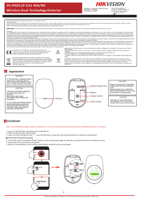
Disclaimer1Appearance2EnrollmentNote:The enrollment progress will be completed in3to10seconds normally,and the maximum enrollment duration is3minutes.1Enroll the Peripheral Locally1.Log in to the APP Store,download and install Hik-Pro.2.Power on the security control panel.3.Log in the APP and tap the icon"+".Scan the QR code or input the control panel serial No.to add the control panel.1.In the APP,tap the"Enrollment Mode"button on the control panel page to make the control panel enter the enrollment status.2.Loosen the screw and remove rear panel.3.Power on the peripheral,and it will be automatically enrolled to the control panel.CAUTIONRISK OF EXPLOSION IF BATTERYIS REPLACED BY AN INCORRECTTYPE.REPLACEMENT OF A BATTERYWITH AN INCORRECT TYPE THATCAN DEFEAT A SAFEGUARD.CAUTIONCHEMICAL BURNING DANGERDO NOT SWALLOW THEBATTERYKEEP NEW AND USEDBATTERIES AWAY FROM THECHILDREN.IF YOU THINK BATTERIES MIGHTHAVE BEEN SWALLOWED ORPLACED INSIDE ANY PART OFTHE BODY,SEEK IMMEDIATEMEDICAL ATTENTION.CAUTIONDISPOSE OF USED BATTERIESACCORDING TO THE INSTRUC-TIONS AND LOCAL REGULATION.CAUTIONIF THE BATTERY COMPARTMENTDOES NOT CLOSE SECURETLY,STOP USING THE PRODUCT ANDKEEP IT AWAY FROM CHILDREN.IndicatorBracket Tamper PortBatteryTamper SwitchPower SwitchEN50131-1:2006+A1:2009+A2:2017EN50131-2-4:2008EN50131-5-3:2017Security Grade(SG)2Environmental Class(EC)IICertified by Telefication1.Check SignalEnter the signal panel.Trigger the detector.Solid Green for 3s -Solid Orange for 3s Solid Red for 3s -Red light flashes for 2.Check the installation environmentNote:Hold the tamper button,and make the device power off and then power on for re-enrollment.3Installation2Enroll the Peripheral with QR and serialNo.1.In the APP ,tap the icon "+"and scan the QR code or serial No.on the peripheral.2.Loosen the screw and remove rear panel.3.Power on the peripheral,and it will be automatically enrolled to the control panel.3.Install the DetectorNote:The additional force shall be equal to three times the weight of the equipment but not less than 50N.The equipment and its associated mounting means shall remain secure during the installation.After the installation,the equipment,includingany associated mounting plate,shall not be damaged.with Screwsa.Knock out the screw holes on the rear panel.with the Sponge TapePaste the device on the wall with sponge tape.b.Secure the rear panel on the wall with four screws.Bracket InstallationCeiling Bracket Fitting (Non EN compliant)Wall Bracket Fitting4TestDetector zones and planesThe zones and plans of the PIRCAM are shown below.10m12m1m2m 4m6m8m85.9°(a)Detection Range 52zones 4planes6Operation Caution and Device Maintenance-All the electronic operation should be strictly compliance with the electrical safety regulations,fire prevention regulations and other related regulations in your local region.-Do not drop the device or subject it to physical shock,and do not expose it to high electromagnetism radiation.Avoid the equipment installation on vibrations surface or places subject to shock (ignorance can cause equipment damage).-Please make sure that the power has been disconnected before you wire,install or dismantle the device.-If smoke,odors or noise rise from the device,turn off the power at once and unplug the power cable,and then please contact the service center.-Do not drop the device or subject it to physical shock,and do not expose it to high electromagnetism radiation.Avoid the equipment installation on vibrations surface or places subject to shock (ignorance can cause equipment damage).-Do not place the device in extremely hot (refer to the specification of the device for the detailed operation temperature),cold,dusty or damp locations,and do not expose it to high electromagnetic radiation.-The device for indoor use shall be kept from rain and moisture.Exposing the equipment to direct sun light,low ventilation or heat source such as heater or radiator is forbidden (ignorance can cause fire danger).-Do not aim the device at the sun or extra bright places.A blooming or smear may occur otherwise (which is not a malfunction however),and affecting the endurance of sensor at the same time.-Improper use or replacement of the battery may result in hazard of explosion.Replace with the same orequivalent type only.Dispose of used batteries according to the instructions provided by the battery manufactur-er.-Do not expose the device to the corrosive gas.Otherwise the equipment damage may occur.-Do not expose the device to the explosive situation.The detector will enter the walk test mode (3minutes)after being enrolled.Trigger the detector within the detection range.If the LED indicator turns blue,the installation position is properly.If the LED indicator is still off,adjust the position of the detector.5FormattingHold the tamper switch for 8s and power the device on at the same time.The red LED flashes 3times when the formatting operation is completed.7Specification。
AX-T02 磁场测试仪用户手册说明书

MAGNET SPACE TESTERAX-T02INSTRUCTIONTABLE OF CONTENTS1. APPLICATIONS GENERAL (3)2. FRONT PANEL DESCRIPTION (3)3. SPECYFICATIONS & WORK DATA (3)4. OPERATING INSTRUCRIONS (4)5. BATTERY REPLACEMENT (4)1. APPLICATIONS GENERAL1) Testing operating solenoid valves in pneumatic and hydraulic control equipment2) Testing relays with coils and electrically controlled solenoid valves in all types of vehicles and machineries3) Testing solenoid valves when servicing oil burners The test lamp lights immediately and without metallic contact where there is a magnetic field, e.g. an activated coil in a solenoid valve. The test lamp responds to all kind of magnetic fields -from alternating current to direct current and to permanent magnets.2. FRONT PANEL DESCRIPTIONBack flashlightFlashlight switch ON/OFFBattery cover&compartmenOFF/ON test switchDetector MagnetBeatSelf test Magnet4. OPERATING INSTRUCTIONS1. Click the "TEST” button and bring the tip of the tester close to the magnetic field.2. Placing the measuring tip to the magnetic field will light up the blue LED at the tip.3) It is not necessary to unscrew the test object from its mounting on the equipment in order to carry out the test – a magnetic coil can even be tested through its protection cover4) It is not necessary to stop the machinery or the equipment in order to carry out the test5) Sometimes stray magnetic fields from other nearby equipment may cause the test lamp to blink momentarily. Close to an activated magnetic coil, however, the test lamp will give a fixed light. 6) Press and hold the back black button for flashlight on, if button undo for flashlight off5. BATTERY REPLACEMENTWhen the battery voltage drops below 2 volts VoltBeat provides a visual indication by stopping the VoltBeat flash. Replace with 2 AAA batteries.Slide the battery cover ( /Fig) and remove the battery. Make sure the battery cover is secure after changing the battery.NOTE: If long time isn’t use please remove battery.。
海康威视网络摄像机用户手册格式说明书

网络摄像机操作手册V2.0.0 杭州海康威视数字技术股份有限公司技术热线:400-700-59982011-3安全须知此内容的目的是确保用户正确使用本产品,以避免危险或财产损失。
在使用此产品之前,请认真阅读此说明手册并妥善保存以备日后参考。
如下所示,预防措施分为“警告”和“注意”两部分:警告:无视警告事项,可能会导致死亡或严重伤害。
注意:无视注意事项,可能会导致伤害或财产损失。
警告事项提醒用户防范潜在的死亡或严重伤害危险。
注意事项提醒用户防范潜在的伤害或财产损失危险。
警告:1.请使用满足SELV(安全超低电压)要求的电源,并按照IEC60950-1符合LimitedPowerSource(有限电源)的额定电压为12V直流或24V交流电源(根据具体型号而定)供应。
2.如果设备工作不正常,请联系购买设备的商店或最近的服务中心,不要以任何方式拆卸或修改设备(未经许可的修改或维修所导致的问题,责任自负)。
3.为减少火灾或电击危险,请勿让本产品受到雨淋或受潮。
4.本安装应该由专业的服务人员进行,并符合当地法规规定。
5.应该在建筑物安装配线中组入易于使用的断电设备。
有关在天花板上安装设备的指示:安装后,请确保该连接至少可承受向下50牛顿(N)的拉力。
注意:1.在让摄像机运行之前,请检查供电电源是否正确。
2.请勿将此产品摔落地下或受强烈敲击。
3.请勿直接碰触到图像传感器光学元件,若有必要清洁,请将干净布用酒精稍微湿润,轻轻拭去尘污;当摄像机不使用时,请将防尘盖加上,以保护图像传感器。
4.避免对准强光(如灯光照明、太阳光等处)聚焦,否则容易引起过亮或拉光现象(这并非摄像机故障),也将影响图像传感其寿命。
5.激光束可能烧毁图像传感器,在激光装置被使用的情况下,请您一定注意不要让图像传感器的表面暴露于激光束之下。
6.避免置于潮湿,多尘,极热,极冷(正常工作温度:-10℃~+60℃),强电磁辐射等场所。
7.避免热量积蓄,请不要阻挡摄像机附近的通风。
DS-8000用户使用手册海康威视版+v1[1][1].5
![DS-8000用户使用手册海康威视版+v1[1][1].5](https://img.taocdn.com/s3/m/9158ecc69ec3d5bbfd0a7458.png)
TU
UT
2.4 报警线连接说明..........................................................................................................................................................................9
TU
UT
3.4 输入法说明................................................................................................................................................................................15
TU
UT
2.1 清点设备及其附件 ......................................................................................................................................................................6
TU
UT
4.3 登录及修改用户名密码 ............................................................................................................................................................16
海康威视磁盘阵列使用说明[精.选]
![海康威视磁盘阵列使用说明[精.选]](https://img.taocdn.com/s3/m/4d37c6ee960590c69ec37668.png)
海康威视磁盘阵列使用说明一.登录1.存储系统默认登录账户为:web_admin 密码为:1232.登录时应以高级模式登录二.设定IP SAN的访问IP管理员可以通过与存储设备相互连通的网络,来设置IP SAN的访问IP。
存储设备分为管理网口和数据网口,可以通过管理网口或者数据网口连接管理PC连接管理网口后,用户可以将用来进行存储管理的设备IP改为同网段的IP,确认网络连接正常后,便可以在IE中输入:https://192.168.10.138:2004来登录IP SAN的管理界面。
一.网络配置下图是系统正常登录后的界面,如图1所示图11.进入系统后,可以首先进入网络管理,在进入网络管理界面后首先要进行网口绑定:点击“绑定管理”按钮,在弹出的界面选择要绑定的网口且绑定模式为“虚拟化”,在点击“创建绑定”并确认绑定成功2.接下来就是“网口管理”,网口管理即就是修改系统IP地址,进入网口管理界面如图2所示:可在此修改系统的访问IP地址图2二.创建RAID1.网络管理之后就是RAID管理,首先要创建阵列,进入“阵列创建”界面,如图3所示图3输入阵列名称,并将阵列类型选为RAID5,然后在可用物理盘中勾选至少3块盘创建阵列,选好后点击“创建阵列”即可。
2.第二步则要进行“阵列重构”,阵列重构是对于已经存在的阵列中,某个物理盘出现不稳定或者出现故障的情况下,为了拯救出故障硬盘中的数据而设定的,从而达到保护数据和恢复阵列的完整性。
但,前提是系统中存在可用的物理盘,并且和出故障的硬盘容量大小相同。
如图4所示图4初始时候阵列自动重构状态默认是关闭的,首先我们要开启自动重构然后输入阵列名称并选择1块可用物理盘,点击“重构阵列”(阵列重构一般是在有故障盘的时候才会用到)3.接下来就要进入“热备盘管理”,热备盘是用来防止阵列中出现掉盘或者磁盘出故障时及时自动化去替换出现故障的硬盘。
其界面如下图5 选择要添加的热备盘点击“添加热备盘”即可图54.之后就是阵列校验,阵列校验的目的是预先防止数据存储过程中出现的错误和长期读写造成的文件丢失,从而达到数据的有效性和完整性。
DS-C10L系列控制器用户手册
DS-C10L系列大屏控制器软件使用说明书Verion 1.0.0杭州海康威视数字技术股份有限公司技术热线:400-700-5998非常感谢您购买我公司的产品,如果您有什么疑问或需要请随时联系我们。
本手册适用于型号为DS-C10L 系列大屏控制器。
本手册可能包含技术上不准确的地方、或与产品功能及操作不相符的地方、或印刷错误。
我司将根据产品功能的增强而更新本手册的内容,并将定期改进或更新本手册中描述的产品或程序。
更新的内容将会在本手册的新版本中加入,恕不另行通知。
若存在手册中对产品的描述与实物不符,一律以实物为准。
目录第1章系统概述 (3)1.1软件系统概述 (3)1.2概念说明 (3)第2章软件操作 (6)2.1系统启动运行 (6)2.2场景存储与调用 (7)2.2.1内场景预设: (7)2.2.2外场景预设: (8)2.2.3窗口操作与调节 (9)2.3系统属性设置 (11)2.3.1窗口属性调节 (11)2.3.2窗口透明处理 (11)2.3.3底图开关处理 (12)2.3.4更换底图 (13)2.3.5矩阵端口配置 (13)2.3.6端口连接与断开 (14)2.3.7键盘快捷键 (15)2.4场景调用协议代码 (15)第3章常见问题解答 (17)第1章系统概述1.1 软件系统概述ApplicationPro是新一代可视化、所见即所得拼接器操控软件, 该操控软件整合拼接器产品的应用特点,结合工程安装上的特点开发完成。
ApplicationPro软件采用目前软件设计的前沿理念,摒弃传统拼接器控制软件复杂的调试要求,对拼接过程实现自动运算,对窗口控制过程采用所见即所得的操作界面,避免传统的拼接器软件繁琐复杂的预设过程;经过简单的培训, 就可以完成对该套软件的使用。
ApplicationPro软件整合墙体拼接控制和窗口控制为一体, 运行该软件可以方便完成对场景的预设、调用、窗口的控制、信号通道选择等功能。
海康威视 智能DVS用户手册V 1.0

第1页共57页1.产品介绍 (5)2、功能介绍 (7)2.1 警戒线跨越检测 (7)2.2 警戒区域入侵检测 (7)2.3 目标离开检测 (8)2.4 目标出现检测 (8)2.5 徘徊检测 (9)2.6 快速移动检测 (9)2.7 物品遗留检测 (10)2.8 非法停车检测 (10)2.9 流量统计功能 (11)2.10 人员密度超标(人员聚集)检测 (11)2.11 物品盗取或移动检测 (12)3.智能客户端使用 (13)3.1 启用客户端 (13)3.2 添加DVS (14)3.3 预览 (18)3.4 启用行为分析配置 (19)3.5 报警规则设置 (21)3.5.1 警戒线设置 (23)3.5.2 警戒区域设置 (24)3.5.3 全局区域设置 (26)3.5.4 规则补充设置 (26)3.6 布防时间和联动方式设置 (28)3.7 设备布防 (31)3.8 报警查看 (32)3.9 报警查询 (34)4.摄像机选择与架设 (40)4.1 摄像机的选择 (40)4.2 摄像机的架设 (41)4.2.1 光线的因素 (41)4.2.2 摄像机高度和角度 (43)4.2.3 摄像机到监控区域的距离 (45)5.规则设置注意事项 (47)5.1 警戒规则的位置 (47)5.2 正确区分“出现”和“进入区域” (48)5.3 警戒区域中报警事件类型对应的参数设置 (48)5.4 尺寸过滤器设置 (48)第3页共57页5.5 算法关键参数设置 (49)6.现场调试/维护 (53)6.1 常见故障排除 (53)6.2 远程升级 (54)第5页 共57页1.产品介绍智能视频服务器(图1.1所示),采用先进的智能视频分析技术,是一种先进的智能视频分析设备,具有周界监控与行为分析的功能,可用于检测、分类、跟踪和记录非法过往行人、车辆及其他可疑物体,能够判断是否有行人及车辆在指定区域内长时间停留、徘徊或逆行等。
杭州海康威视数字技术有限公司产品使用与管理指南说明书
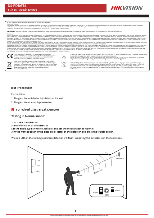
DisclaimerTest ProceduresFor Wired Glass Break DetectorTesting in Normal mode:1.Activate the detector:Stand within 3m of the detector.Set the audio type switch to Activate ,and set the mode switch to Normal .Aim the front speaker of the glass break tester at the detector,and press the trigger button.The red LED on the wired glass break detector will flash,indicating the detector is in the test mode.Precondition:1.The glass break detector is installed on the wall.2.The glass break tester is powered on.12.Test:According to the glass type,set the audio type switch to Tempered or Float/Plate.Position the tester near the glass(8m Max.between the detector),and aim the front speaker of the glass break tester at the detector.Press the trigger button and the tester will play glass break audio.The blue LED on the detector will light,indicating the detector is triggered successfully.Testing in Flex mode:According to the glass type,set the audio type switch to Tempered or Float/Plate,and set the mode switch to Flex. Position the tester near the glass(8m Max.between the detector),and aim the front speaker of the glass break tester at the detector.Press the trigger button and the red LED will stay on for10seconds.Within the10seconds,knock on the table or glass to produce a low frequency sound.The tester will play glass break audio when the sound is recognized.The blue LED on the detector will light,indicating the detector is triggered successfully.For Wireless Glass Break Detector2Testing in Normal mode:1.Activate the detector:In Hik-Connect APP,select glass break detector.Tap Settings→Detection Zone Test,and slide to the Glass Break Test page to click Start.The red LED on the wireless glass break detector will flash,indicating the detector is in the test mode.2.Test:According to the glass type,set the audio type switch to Tempered or Float/Plate.Position the tester near the glass(8m Max.between the detector),and aim the front speaker of the glass break tester at the detector.Press the trigger button and the tester will play glass break audio.The blue LED on the detector will light,indicating the detector is triggered successfully.Testing in Flex mode:According to the glass type,set the audio type switch to Tempered or Float/Plate,and set the mode switch to Flex. Position the tester near the glass(8m Max.between the detector),and aim the front speaker of the glass break tester at the detector.Press the trigger button and the red LED will stay on for10seconds.Within the10seconds,knock on the table or glass to produce a low frequency sound.The tester will play glass break audio when the sound is recognized.The blue LED on the detector will light,indicating the detector is triggered successfully.UD26516B。
- 1、下载文档前请自行甄别文档内容的完整性,平台不提供额外的编辑、内容补充、找答案等附加服务。
- 2、"仅部分预览"的文档,不可在线预览部分如存在完整性等问题,可反馈申请退款(可完整预览的文档不适用该条件!)。
- 3、如文档侵犯您的权益,请联系客服反馈,我们会尽快为您处理(人工客服工作时间:9:00-18:30)。
1.2 地磁管理器
特征:
ISM 频段的无线数据通信 适用于通用工业控制目的 适用于数字互连目的 通用的 ISM 频段 低功率运行(具有睡眠周期) 阻燃外壳 发射数据接收数据及路由功能 +17 dBm(最大值)RF 发射功率,可下降到-110dBm 的接收灵敏度 无线配置 状态监测与 LED 显示屏 嵌入看门狗定时器电路可以自动恢复正常运行 保护 DTE 接口的 ESD,±15kV (IEC1000) 保护数字输出端口的 TVSS DTE 接口的串行(RS232/RS485)数据互连端口 支持 GPRS 无线数据上传(DS-TDP210-SG) 支持 TCPIP 有线数据上传(DS-TDP210-ST)
(忽视此项可能会导致火灾危险)。 请妥善保存设备全部原包装材料,以便出现问题时,使用包装材料将设备包装好,
寄到代理商或返回厂家处理。非原包装材料导致的运输途中的意外损坏,由使用 者承担责任。
iii
地磁管理器与检测器 用户手册
目录
第 1 章 概览 .................................................................................................................................. 1 1.1 地磁检测器...................................................................................................................... 1 1.2 地磁管理器...................................................................................................................... 2
RF 频道:
32 个(470Mhz)频道
RF 互连距离:
典型值为 500 米(根据射频功率和环境而定)
1
地磁管理器与检测器 用户手册
RF 传输速率:
2500bps 的数据速率 无线配置参数
参数
1
射频发射功率
2
心跳间隔
3
RF 频道
4
探测器 ID
5
群组 ID
描述 最大+15dBm 1 ~7200 (s) 最多为 32 个频道 32Bit ID 0x2FFF
请不要使物体摔落到设备上或大力振动设备,使设备远离存在磁场干扰的地点。 避免将设备安装到表面振动或容易受到冲击的地方(忽视此项可能会损坏设备)。
请不要在高温、低温或者高湿度的环境下使用设备。
ii
地磁管理器与检测器 用户手册 避免将设备放在阳光直射地点、通风不良的地点,或如加热器或暖气等热源附近1射频发射功率2
RF 频道
3
探测器 ID
4
群组 ID
描述 最大+15dBm 最多为 32 个频道 32Bit ID 0x2FFF
3
地磁管理器与检测器 用户手册
第2章 施工与安装
2.1 施工
1. 打孔开凿需要 96 的开孔器,开孔深度为 9-10cm.。
4
地磁管理器与检测器 用户手册
2. 开孔的位置分两种: 非字形车位: 在附近没有金属、高压电缆或者其他干扰的情况下,如果是有定位柱的话,安装位置 距离定位柱 3 米。如果没有定位柱孔位就开在靠马路侧,车轴的正中下方。 如图:
关于本手册
本手册描述的产品仅供中国大陆地区销售和使用。
本手册作为指导使用。手册中所提供照片、图形、图表和插图等,仅用于解释和说明 目的,与具体产品可能存在差异,请以实物为准。因产品版本升级或其他需要,海康 威视可能对本手册进行更新,如您需要最新版手册,请您登录公司官网查阅 ()。
2
地磁管理器与检测器 用户手册
RF 发射功率:
+17 dBm(最大值)
RF 接收灵敏度:
-110dBm(典型值)
RF 互连距离:
探测器到接收器:典型值为 500 米(根据射频功率和环境而定) 接收器到接收器:典型值为 2000 米(根据射频功率和环境而定) 无线配置参数
参数
地磁管理器与检测器 用户手册
地磁管理器与检测器
用户手册
UD.6L0110D0086A01
地磁管理器与检测器 用户手册
版权所有©杭州海康威视数字技术股份有限公司 2015。保留一切权利。
本手册的任何部分,包括文字、图片、图形等均归属于杭州海康威视数字技术股份有 限公司或其子公司(以下简称“本公司”或“海康威视”)。未经书面许可,任何单位 和个人不得以任何方式摘录、复制、翻译、修改本手册的全部或部分。除非另有约定, 本公司不对本手册提供任何明示或默示的声明或保证。
7
8
海康威视建议您在专业人员的指导下使用本手册。
商标声明
拥有。
为海康威视的注册商标。本手册涉及的其他商标由其所有人各自
责任声明
在法律允许的最大范围内,本手册所描述的产品(含其硬件、软件、固件等)均“按 照现状”提供,可能存在瑕疵、错误或故障,海康威视不提供任何形式的明示或默示 保证,包括但不限于适销性、质量满意度、适合特定目的、不侵犯第三方权利等保证; 亦不对使用本手册或使用本公司产品导致的任何特殊、附带、偶然或间接的损害进行 赔偿,包括但不限于商业利润损失、数据或文档丢失产生的损失。
一字型车位: 在附近没有金属、高压电缆或者其他干扰的情况下, 安装在车位的中间的车位线上。 如图:
5
地磁管理器与检测器 用户手册
3. 通讯网关 选择地感分布的中心位置,并需要接入 AC 200V 和一根网线。
6
地磁管理器与检测器 用户手册
2.2 安装
安装过程中需要注意设备标签箭头应该朝南安装,并浇灌混凝土。 根据实际安装情况,填写车位对应的表格(车位编号对应的设备产品编号)
安全使用注意事项
产品安装使用过程中,必须严格遵守国家和使用地区的各项电气安全规程。
请使用正规厂家提供的电源适配器。 在接线、拆装等操作时请一定要将智能球电源断开,切勿带电操作。 如果设备出现冒烟现象,产生异味,或发出杂音,请立即关掉电源并且将电源线
拔掉,及时与经销商或服务中心联系。
如果设备工作不正常,请联系购买设备的商店或最近的服务中心,不要以任何方 式拆卸或修改设备。(对未经认可的修改或维修导致的问题,本公司不承担任何 责任)。
前言
本节内容的目的是确保用户通过本手册能够正确使用产品,以避免操作中的危险或财 产损失。在使用此产品之前,请认真阅读产品手册并妥善保存以备日后参考。
符号约定
对于文档中出现的符号,说明如下所示:
符号
说明 说明类文字,表示对正文的补充及解释。 注意类文字,表示对用户的提醒,提醒用户一些重要的操作或者防范潜 在的伤害和财产损失危险。 警告类文字,表示提醒用户防范潜在的死亡或者严重伤害危险。
第 2 章 施工与安装....................................................................................................................... 4 2.1 施工.................................................................................................................................. 4 2.2 安装.................................................................................................................................. 7
使用本产品时,请您严格遵循适用的法律。若本产品被用于侵犯第三方权利或其他不 当用途,海康威视概不承担任何责任。
如本手册内容与适用的法律相冲突,则以法律规定为准。
本手册适用于以下产品:
产品系列 DS-TDP1XX-S DS-TDP2XX-S
0100001050428
i
地磁管理器与检测器 用户手册
1
地磁管理器与检测器 用户手册
第1章 概览
1.1 地磁检测器
特征:
地磁检测器是基于 MP-AMR(微功率地磁感应检测)技术的用于 PIS 和 PDS 应用的 一体化 ISM 无线地磁感应停车场检测器。 以微功率地磁感应车辆检测技术(MP-AMR)为基础 电池供电工作 抗压外壳,可用于室内和室外的停车信息系统(PIS)应用 ISM 频段的无线通信 电池寿命长,且可更换电池 工作的温度范围大且防水 易于安装 易于维修 超低功耗,超长工作时间 覆盖半径广,覆盖容量大 环境因素自动补偿算法 无线数据传输,无线参数设置 故障监控,电池监测,低电量自动报警 对室内和室外应用都具防水功能 防静电,12K 电弧放电,3K 接触放电