恒强制版说明书
恒强制版980教程说明书

恒强制版980教程说明书
恒强制版980一右键一打开一文件新建花板一设置画布大小
F2:回到可布原点。
F3:切换花样一引塔夏。
F5:上一色。
F6:下一色。
F9:切换网络线。
F10:扩到最大或者缩到最小。
F11:缩小。
F12:扩大。
注意:开始制版时需将画布扩大到能看到模拟组织然后按F2让画布回到原点,每一个版子,必须从原点开点。
工艺单上面,一转等于画布两行。
画笔:在画布任一位置点击一针一行。
直线:在画布里画出一行选定的色码。
填充距行:在画布里画出要求的行数及针数,另一用法当画错时可选定0号色将其区域涂上。
复制工具:
1、选取选择框
将框住的区域进行任意地方的挪动。
2、线行复制
将框住的区域进行360度的有机律复制。
3、阵列复制
将框住的区域进行直列或竖列的复制。
4、多重复制
将框住的区域按照自已选择的规律进行复制做收针时候用最多。
复制工具用法:
1、左键点击需要的复制工具。
2、在画布里选择需要的复制的区域电机左键确定。
3、在区域里继续点左键移动鼠标进行复制。
4、达到要求后点左键确定。
HQPDS 恒强制版更新 中文
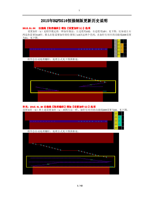
2015年HQPDS16恒强制版更新历史说明2015.01.04 功能线【取消编织】增加【设置加针(1)】选项设置加针(1)是程序既定的一种加针做法,左边使用102,右边使用104。
见下图,比如说左右两边各需要加10针,那么在您需要加针的位置填上10次这两个色码,在加针行对应的功能线203设置为21。
见下图。
程序会自动处理翻针,处理方式见下图黄框处。
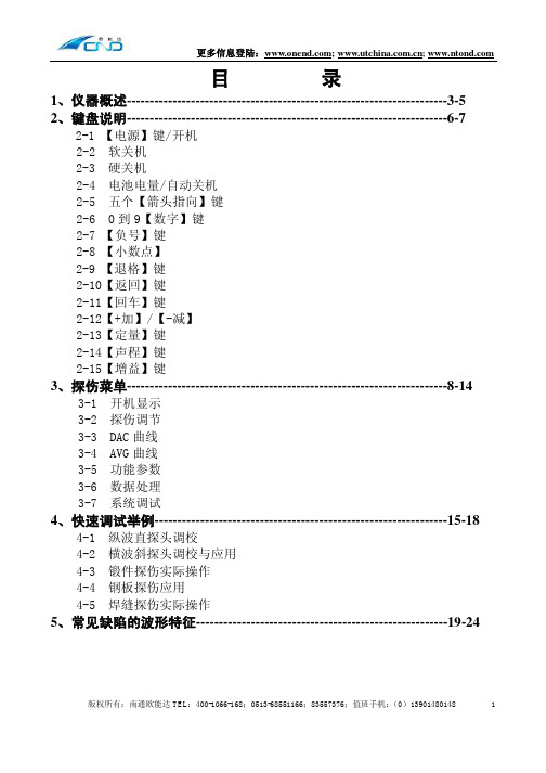
补充:2015.01.20 功能线【取消编织】增加【设置加针(2)】选项设置加针(2)和上述设置加针(1)画图方法一样,加针行对应的功能线203设置为22,见下图。
程序会自动处理翻针,处理方式见下图黄框处。
2015.01.05 功能线【取消编织】增加【自动加针】选项自动加针是程序既定的一种加针做法,不需要特定的符号,比如说左右两边各需要加10针,那么在您画图按下面图片的方法,然后在加针行对应的功能线203设置为12。
见下图。
程序会自动计算针数来实现加针。
2015.01.06 工艺单参数增加【分别翻针】开关意思是在下图中将“分别翻针”打勾,则生成的图形对应的功能线224里会自动设置为分别翻针1,不需要手工在功能线224里面设置分别翻针了。
2015.01.07 工艺单参数支持设置【缩针】段数意思是支持我们制版者自由设置缩针行的度目段。
见下图。
2015.01.08 工艺单参数增加【主纱落布行数】设置用于设置主纱落布行数,见下图,设置为20行则生成的图形中箭头处为20行,见下图。
2015.01.09 工艺单其他类型支持【加针】选项是指工艺单输入中支持设置加针,见下图。
2015.01.10 编译选项增加【展开节约(2)】设置见下图,在功能线201设置了节约(2)为3次编译时,将展开节约(2)打勾,见下图编译后,可以看到程序自动将3次节约展开了。
见下图。
2015.01.13 高级设置中支持设置横机【F3切换"花样<-->引塔夏"】开关意思是按快捷键F3 ,可以切换下面这几个图层。
欧能达横版新说明书
1
更多信息登陆:; ;
6、探伤数据的保存和探伤报告的打印-------------------------------------25-34
6-1 U 盘探伤文件的打开 6-2 如何修改或填写报告内容 6-3 仪器和计算机的通讯步骤 6-4 录像文件的打开 (部分仪器具有此功能,参考型号说明) 6-5 如何将修改之后的新的探伤报告格式上传到仪器
3、探伤菜单----------------------------------------------------------------------8-14
3-1 开机显示 3-2 探伤调节 3-3 DAC 曲线 3-4 AVG 曲线 3-5 功能参数 3-6 数据处理 3-7 系统调试
4、快速调试举例----------------------------------------------------------------15-18
4-1 纵波直探头调校 4-2 横波斜探头调校与应用 4-3 锻件探伤实际操作 4-4 钢板探伤应用 4-5 焊缝探伤实际操作
5、常见缺陷的波形特征-------------------------------------------------------19-24
版权所有:南通欧能达 TEL:400-1066-168;0513-68551166;83557376;值班手机: (0)13901480148
【电源】键/开机:
按住“电源”键一秒种后,仪器显示有关您单位和生产厂家以及该仪器的详细信息。 此时按超声探伤即进入探伤画面。 其余功能为针对特别用户使用,也许您无法使用。
软关机:
该仪器为高度数字集成化产品,所以建议您正常使用时用“软关机”来关闭仪器,这样可以确保您已保存 的参数在任何状态下都不会丢失。 “软关机”在“数据处理”菜单下选择“关闭电源”即可。
Strongway 扁平钢筋拆卸机说明书

Drum DeheaderOwner’s ManualWARNING: Read carefully and understand all ASSEMBLY AND OPERATION INSTRUCTIONS before operating. Failure to follow the safety rules and other basic safety precautions may result in serious personal injury.Item #52860Thank you very much for choosing a Strongway™ product!For future reference, please complete the owner’s record below:Serial Number/Lot Date Code: ________________________________ Purchase Date: ____________________________________________ Save the receipt, warranty, and this manual. It is important that you read the entire manual to become familiar with this product before you begin using it.This Drum Deheader is designed for certain applications only. Northern Tool and Equipment is not responsible for issues arising from modification or improper use of this product such as an application for which it was not designed. We strongly recommend that this product not be modified and/or used for any application other than that for which it was designed.For technical questions, please call 1-800-222-5381.Intended Use (4)Technical Specifications (4)Important Safety Information (4)Operating Instructions (5)Maintenance (7)Parts Diagram (7)Parts List (7)Replacement Parts (7)Limited Warranty (8)Strongway’s Drum Deheader c uts the top off a standard 30- to 55-gallon industrial steel drum, leaving a smooth edge around the rim, enabling the drum to be reused. Deheading a drum becomes an easy one-person operation. The tool is made of forged steel with a replaceable alloy steel blade.1. Turn the knob (A) counterclockwise to leave space for the shaft on the cutter base (C) to fit intothe hole of the bracket (B) and create more clearance between the cutter base (C) and the blade(D). An adjustment will extend the deheader to its fully open position for maximum bladeclearance over the drum chime.2. Tilt the deheader handle away from you. Place the groove in the cutter base (C) on top of thedrum chime (Figure 2) and place the blade (D) over the chime, making sure the blade (D) will not be affected by the cutter base (C).Fig. 23. Turn the knob (A) clockwise slowly until the cutter base (C) is firmly in contact with the side of thedrum. The drum deheader is now firmly attached to the drum and the blade is now in contact with the inside edge of the chime. Turn the knob (A) counter-clockwise slightly, so the blade does not bind and wedge the drum chime between the blade and the cutter base. The deheader should now be positioned similar to Figure 3.Fig. 34. To begin cutting, press down on the handle (F) until the blade punctures the drum head (Figure5). Raise the handle, and slide the drum deheader to make the next cut. See Figure 4.Figure 4 Figure5Note: Each time you overlap a cut, the edge will become smoother.5. Repeat step 4 until the desired cut is complete.1. Lubricate moving parts periodically.2. Check bolts and nuts frequently for tightness.∙For replacement parts and technical questions, please call Customer Service at 1-800-222-5381. ∙Not all product components are available for replacement. The illustrations provided are a convenient reference to the location and position of parts in the assembly sequence. ∙When ordering parts, the following information will be required: item description, item model number, item serial number/item lot date code, and the replacement part reference number. ∙The distributor reserves the rights to make design changes and or improvements to product lines and manuals without notice.A KnobB BracketC Cutter BaseD BladeE LeverF HandleNorthern Tool and Equipment Company, Inc. ("We'' or '"Us'') warrants to the original purchaser only ("You'' or “Your”) that the Strongway product purchased will be free from material defects in both materials and workmanship, normal wear and tear excepted, for a period of one year from date of purchase. The foregoing warranty is valid only if the installation and use of the product is strictly in accordance with product instructions. There are no other warranties, express or implied, including the warranty of merchantability or fitness for a particular purpose. If the product does not comply with this limited warranty, Your sole and exclusive remedy is that We will, at our sole option and within a commercially reasonable time, either replace the product or product component without charge to You or refund the purchase price (less shipping). This limited warranty is not transferable.Limitations on the WarrantyThis limited warranty does not cover: (a) normal wear and tear; (b) damage through abuse, neglect, misuse, or as a result of any accident or in any other manner; (c) damage from misapplication, overloading, or improper installation; (d) improper maintenance and repair; and (e) product alteration in any manner by anyone other than Us, with the sole exception of alterations made pursuant to product instructions and in a workmanlike manner.Obligations of PurchaserYou must retain Your product purchase receipt to verify date of purchase and that You are the original purchaser. To make a warranty claim, contact Us at 1-800-222-5381, identify the product by make and model number, and follow the claim instructions that will be provided. The product and the purchase receipt must be provided to Us in order to process Your warranty claim. Any returned product that is replaced or refunded by Us becomes our property. You will be responsible for return shipping costs or costs related to Your return visit to a retail store.Remedy LimitsProduct replacement or a refund of the purchase price is Your sole remedy under this limited warranty or any other warranty related to the product. We shall not be liable for: service or labor charges or damage to Your property incurred in removing or replacing the product; any damages, including, without limitation, damages to tangible personal property or personal injury, related to Your improper use, installation, or maintenance of the product or product component; or any indirect, incidental or consequential damages of any kind for any reason.Assumption of RiskYou acknowledge and agree that any use of the product for any purpose other than the specifieduse(s) stated in the product instructions is at Your own risk.Governing LawThis limited warranty gives You specific legal rights, and You also may have other rights which vary from state to state. Some states do not allow limitations or exclusions on implied warranties or incidental or consequential damages, so the above limitations may not apply to You. This limited warranty is governed by the laws of the State of Minnesota, without regard to rules pertaining to conflicts of law. The state courts located in Dakota County, Minnesota shall have exclusive jurisdiction for any disputes relating to this warranty.Distributed by:Northern Tool & Equipment Company, Inc.Burnsville, Minnesota 55306Made in China。
浙江恒旺电子有限公司产品说明书

RangeFinder Work Flow/telegesissupportZigBee RangeFinderQuick Start Guide(h)(i)(j)(a)(b)(e(g)Handheld (HHT)(a) Product Model Number (b) LCD Display (c) Navigation Keys (d) Value Change Keys (e) Escape (Back) Key (f) Enter (Activate) Key (g) Power On/Off KeySatellite (IHD and GAS) (h) Product Model Number (i) Power On/Off Key(j) Activity and Battery Status IndicatorIssue: 4Date: Aug 2013 Start GuidePre -TestThis is used to test the link between the Range Finder handheld unit and the satellites IHD and GAS.The results are shown in the following screen and include: ∙ Serial number of the IHD or GAS unit. ∙ Battery capacity at IHD and GAS units. ∙ RSSI level measure during the Pre -Test.∙ Overall result of ‘OK’ or ‘NOK’ for Pre -Test Pass orFail.The bottom row shows:∙ The Zigbee RF channel used for Pre -Test. ∙ The transmit power used for Pre -Test. ∙ The battery status of handheld unit.Pre -Test transfers all the test settings from HHT to the IHD and GAS units for current session, so it is important to get an OK from this test in order to perform any further tests. Press ESC key to exit the test and go back to menu screen.Data Logging Configuration (Data Logger)The HHT will record the results from Test -A/B and Energy Scan into built -in storage. After exiting the welcome screen the data logging config screen will appear which enables the operator to enter the SITE ID for the current session. The SITE ID will be stored with the test results of the cur-rent session (more details in the user manual). At every new site, changethe SITE ID by navi-gating to EDIT option on screen using keys and press OK. The SITE ID is an alphanumeric field of 16 characters and can be edited by using keys.Once the SITE ID is changed press OK key on keypad to hear a beep from device as confirmation.Please enter a unique SITE ID for each location as this is used as record identifier in the data logs. This option can also be accessed by selecting “Data Logger” menu option on Menu Screen 2.Main Menu Screen 1Use navigation keys to scroll through various menuTo use both IHD and GAS for test. To use only IHD for test.Press OK to use the setting for the current session or to select any menu option.The battery symbol indicates the capacity or charging status of the battery of the handheld. Further details of Menu Screen 2 options can be found in the user manual. Using the Range Finder Power On/Off∙ To power on press the Power Key (g) for about 3 sec-onds until the Welcome Screen is displayed∙ To power off press the Power Key (g) until the screengoes blankWelcome ScreenUpon power up the welcome screen pops up displaying information about the device firmware and the serial num-bers of devices paired as shown below. Press any key to exit from this screen.IG I Specifications:RF Interface:Wireless Standard: 2.4GHz IEEE802.15.4 Output Power: - 9 to +8dBmRF Channels: 11,14,15,19,20,24,25Antenna:Half Wave Dipole Antenna with 2dBi GainElectrical:Battery HandheldType: 2x 1.2V 2000mAH NiMH rechargeable Expected Life: 5 Days [150 x 15 min cycles] Charging: 5 Volts @ 300mAvia USB Micro Connector Battery SatelliteType: 2x 1.5V AlkalineExpected Life: 5 Days [150 x 15 min cycles]Environmental:Operating Temperature: 0 to 50C Humidity: 95% RH non -condensing IP Rating: IP54Test BTest B is similar to Test A except it tests the link between the HHT and the IHD and GAS units on channels 20,24 and 25. The result screen is as shown:Energy ScanAn energy scan across all channels specified by the 2.4GHz 802.15.4 standard is performed and the result is shown. The Energy Scan results for each channel are painted on the screen as the scan progresses.The channel number ‘0’ corresponds to channel 11 of the ZigBee 2.4GHz RF spectrum. The channels which are tested in Test A and B are highlighted.Configuration Settings Screen (Config)Usenavigation keys to scroll through different set-tings.Press OK to select the set-ting andkeys to edit it.Once edited again press OK to set the value for the configu-ration setting. If the value is set correctly the device will beep once to con-firm changein setting.The ‘CDT’ option has a valid range of 10 to 120 seconds. This value is the countdown time used during Test A and Test B. if this setting is changed here, the change will be volatile (i.e. CDT will be reset to the default value after power up) The PIN protected configuration settings aredescribed in detail in the user manual.The RangeFinder has 10 built -in profiles of all the settings which are required to perform tests which could be assigned to each device (HHT/IHD/GAS) individually. To assign the setting to any device navigate to the device name using keys and press OK. Test ATest A checks the link between HHT and the IHD and GAS units on channels 11,14,15 and 19. At the start of test a countdown timer gives the operator a chance to place the HHT unit in the test location and move away. Count down time can be changed in the Configuration Settings Screen.or cross respectively in the right hand which failed is highlighted. The red backlight turns ON if link failure occurs on two or more channels.Values under label ‘T’ - RSSI in dBm at HHT ‘S’ - RSSI in dBm at SATNote : On all menu screens the keys will adjust the contrast of the display . Be careful while changing the contrast as it might lead to a blank or completely dark screen.。
恒强HQPDS 制版系统更新 中文
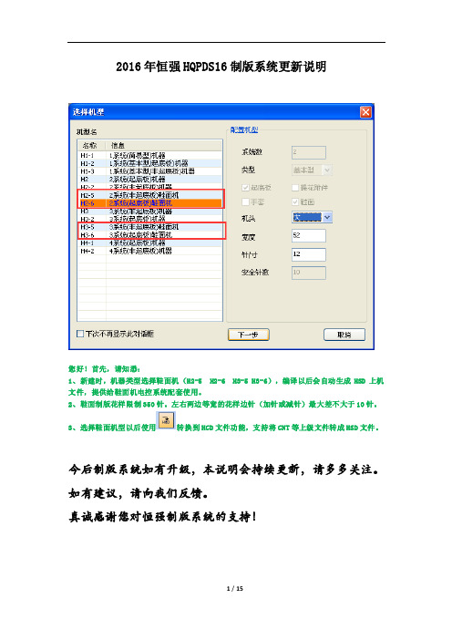
2016年恒强HQPDS16制版系统更新说明您好!首先,请知悉:1、新建时,机器类型选择鞋面机(H2-5 H2-6 H3-5 H3-6),编译以后会自动生成HSD上机文件,提供给鞋面机电控系统配套使用。
2、鞋面制版花样限制350针。
左右两边等宽的花样边针(加针或减针)最大差不大于10针。
3、选择鞋面机型以后使用转换到HCD文件功能,支持将CNT等上级文件转成HSD文件。
今后制版系统如有升级,本说明会持续更新,请多多关注。
如有建议,请向我们反馈。
真诚感谢您对恒强制版系统的支持!2016.01.04 修正提花组织图功能支持IC/IJ色码的不同处理【方式】看上图,局部提花时箭头处的位置需要做出修正,那么可以使用这个工具,让程序自动进行修正,方式有三种,见下图。
修正后的结果见下图。
2016.01.06 增加【编织+粗目】色码前床编织后粗目,意思是前床正常度目后床二段度目,后床线圈为紧目。
后床编织前粗目,意思是后床正常度目前床二段度目,前床线圈为紧目。
2016.01.07 横机工具增加【设置纱嘴度目】功能2016.01.09 编译选项支持设置提花【按纱嘴翻针】提花含有翻针,一般情况下是提花的一组纱嘴全部织完再翻针,见下图:如果编译时将“按纱嘴翻针”勾选,则织完前床纱嘴就会翻针,见下图:2016.01.08 高级参数中支持自定义花型权限控制【帐号】见下图箭头处的红圈内,支持我们在花型控制权限这里自由设定帐号,设定后请将帐号记牢。
比如给某花样设定了帐号为335,见下图。
当您把设定了帐号为335的花样发送给别人以后,别人打开此花样时,程序都会自动提示请输入帐号,见下图。
届时输入帐号335即可。
2016.01.09 高级参数中支持设置横机【自动加载编译选项】意思是当打开某个花样时,程序会自动将此花样最后一次的编译选项加载进来。
2016.01.11 高级参数中支持设置横机【自动加载工艺单】意思是当打开某个花样时,会同步将当初生成此花样的工艺单自动加载为当前工艺。
强Arm 重型三阶段扬平机说明书

REF LHJ01 LHJ02 LHJ03 LHJ04 LHJ05 LHJ06 LHJ07 LHJ08 LHJ09 LHJ10 LHJ11 LHJ12 LHJ13 LHJ14 LHJ15 LHJ16 LHJ17 LHJ18 LHJ19 LHJ20 LHJ21 LHJ22 LHJ23 LHJ24 LHJ25
REF LHJ51 LHJ52 LHJ53 LHJ54 LHJ55 LHJ56 LHJ57 LHJ58 LHJ59 LHJ60 LHJ61 LHJ62 LHJ63 LHJ64 LHJ65 LHJ66 LHJ67 LHJ68
PART NUMBER PCN-780SHD-LHJ51 PCN-780SHD-LHJ52 PCN-780SHD-LHJ53 PCN-780SHD-LHJ54 PCN-780SHD-LHJ55 PCN-780SHD-LHJ56 PCN-780SHD-LHJ57 PCN-780SHD-LHJ58 PCN-780SHD-LHJ59 PCN-780SHD-LHJ60 PCN-780SHD-LHJ61 PCN-780SHD-LHJ62 PCN-780SHD-LHJ63 PCN-780SHD-LHJ64 PCN-780SHD-LHJ65 PCN-780SHD-LHJ66 PCN-780SHD-LHJ67 PCN-780SHD-LHJ68
J016 SCREW PCN-760SHD-J016 J017 FILL SCREW PLUG PCN-780SHD-J017 J018 SCREWS PCN-750SHD-J018 J019 SCREWS PCN-750SHD-J019
SHD HEAVY DUTY 3 STAGE JACK PROD NO 030477 MODEL 780SHD
NovaWrap Aspire 强化建筑纸说明书

• After installation is complete, and before exterior cladding is installed, inspect the NovaWrap™ Asp4iinroev™erlfaopr tears. If issues are found, tape the imperfections with Tuck® Tape Sheathing Tape.
• IPG® recommends that NovaWrap™ Aspire™ should be covered with cladding and the wall cavity closed within 60 days of installation.
Inverted Y cut
Inverted Y cut
• A concealed airspace exceeding 1 inch (2.5 cm) in width must contain proper fire stopping in accordance with Subsection 9.10.16 of the NBC 2015.
• Although NovaWrap™ Aspire™ is stabilized with respect to degradation from sunlight for six (6) months, it should 6ninootvebrleapleft exposed to sunlight indefinitely.
• When installing over metal framing, use capped screws with washers.
• Fasteners should be spaced at maximum 32 inches (81cm) OC (both vertically and horizontally).
- 1、下载文档前请自行甄别文档内容的完整性,平台不提供额外的编辑、内容补充、找答案等附加服务。
- 2、"仅部分预览"的文档,不可在线预览部分如存在完整性等问题,可反馈申请退款(可完整预览的文档不适用该条件!)。
- 3、如文档侵犯您的权益,请联系客服反馈,我们会尽快为您处理(人工客服工作时间:9:00-18:30)。
恒强制版系统使用说明
10.2 首次使用 ................................................................................................................. 139 10.3 画图 ......................................................................................................................... 145 10.4 纱嘴设置 ................................................................................................................. 150 10.6 自动编程(自动出带).............................................................................................. 151 10.7 拆分图查看 ............................................................................................................. 152 10.8 拆分图示例(ABC.EXE 编译) .................................................................................... 152 11. 部分针法图解........................................................................................................................155 11.1 单面正针(前床) ...................................................................................................... 155 11.2 单面反针(后床) ...................................................................................................... 156 11.3 四平编织(总针)....................................................................................................... 157 11.4 1X1 单罗纹 ............................................................................................................ 157 11.5 2X1 双罗纹(2X1 坑条).......................................................................................... 158 11.6 2X2 双罗纹(2X2 坑条).......................................................................................... 159 11.7 挑孔(网眼/纱罗组织) .......................................................................................... 159 11.8 绞花(扭绳) ............................................................................................................... 160 11.10 提花(单面提花/单面拉虚线) .............................................................................. 161 11.11 嵌花(INTARSIA) ........................................................................................................ 162 12. 附件 色块表..........................................................................................................................163
加载................................................................................................................................... 118 保存................................................................................................................................... 119 8.7 工艺单的新建............................................................................................................. 120 8.8 鼠标右键功能说明 ..................................................................................................... 121 9. 工作区...................................................................................................................................133 10. 初学者使用............................................................................................................................139 10.1 软件安装 ................................................................................................................. 139
4.1 绘图设计 ...................................................................................................................... 5 4.2 文件操作 ...................................................................................................................... 6 4.3 花样文件类型 .............................................................................................................. 6 4.4 程式自动生成 .............................................................................................................. 8 4.5 程式资料编辑 .............................................................................................................. 8 4.6 工艺单成型 .................................................................................................................. 8 5. 工具栏(tools box) ..................................................................................................................9 5.1 工具栏图标 ................................................................................................................ 10 5.2 常规工具栏图标 .......................................................................................................... 39 5.3 作图区编织色码 .......................................................................................................... 48 5.4 菜单栏 .......................................................................................................................... 50 6. 快捷键.....................................................................................................................................58 7. 功能线作图区、指示栏.........................................................................................................61 7.1 功能线表 ...................................................................................................................... 61 7.2 部分功能线操作说明 .................................................................................................. 69 8. 工艺单成型.............................................................................................................................83 8.1 新建 .............................................................................................................................. 83 8.2 工艺单 .......................................................................................................................... 83 8.3 工艺单图标及参数说明 ............................................................................................... 84 8-4 工艺单中高级参数的设置说明................................................................................... 97 8.5 其他功能运用............................................................................................................. 112 8.6 工艺单的加载、保存 ................................................................................................. 118