BAKE HUGES旋转导向操作手册20190112-中文
旋转导向原理及应用
51旋转导向原理及应用马 速 中石化胜利石油工程有限公司钻井工程技术公司【摘 要】旋转导向钻井系统实质上是一个井下闭环变径稳定器与测量传输仪器.它完全抛开了滑动导向方式,而以旋转导向钻进方式,自动、灵活地调整井斜和方位,大大提高了钻井速度和钻转导向钻进方式,轨迹控制精度也非常高。
【关键词】旋转导向;偏置稳定器;推靠式旋转导向;指向式旋转导向迄今为止,定向钻井技术经历了三个里程碑:利用造斜器(斜向器)定向钻井;利用井下马达配合弯接头定向钻井;利用导向马达(弯壳体井下马达弯壳体井下马达)定向钻井。
这三种定向钻井工具的广泛使用,促进了定向钻井技术的快速发展,使得今天人们能够应用斜井、丛式井、水平井、水平分支井技术开发油田。
为了克服滑动导向技术的不足,从20世纪世纪80年代后期,国际上开始研究旋转导向钻井技术,到20世纪世纪90年代初期多家公司形成了商业化技术。
旋转导向钻井系统实质上是一个井下闭环变径稳定器与测量传输仪器。
它完全抛开了滑动导向方式,而以旋转导向钻进方式,自动、灵活地调整井斜和方位,大大提高了钻井速度和钻井安全性,轨迹控制精度也非常高,非常适合目前开发特殊油藏的超深井、高难度定向井、水平井、大位移井、水平分支井等特殊工艺井导向钻井的需要。
一、旋转导向钻井系统的特点第一,在钻柱旋转的情况下,具有导向能力;第二,如果需要,可以与井下马达一起使用; 第三,配有全系列标准的地层参数及钻井参数检测仪器;第四,配有地面—井下双向通讯系统,可根据井下传来的数据,在不起钻的情况下从地面发出指令改变井眼轨迹;第五,工具设计制造模块化、集成化;第六,可以在150℃以上的高温井中使用;第七,定向钻井时不需要特殊的钻井参数,以保证准确光滑的井眼轨迹。
二、目前国际上常见的旋转导向钻井系统法国Schlumberger Anadrill公司的R .L.Monti在在1987年世界石油年世界石油大会上宣读的“Optimized Drilling”论文中,对自动化闭环优化钻井技术第一次做了系统的阐述。
旋转压实仪操作手册1

欧美大地
欧美大地
6. 质保 ...............................................................................................................6 7. 安全密码 ........................................................................................................6
压实角度 压实转速: 压实圈数 数据采集 每圈记录一次
欧美大地
600 kPa (固定) ± 60 kPa 压实圈数0-5 ± 10 kPa 压实圈数大于5 1.20 - 1.30 度 30 ±1/2 rpm 0-999 试件高度 (mm) 旋压角度 (度) 压强 (kPa) 1.44 Mb (3.5”) 软驱 打印机 (选项) RS-232 (波特率 2400) (需要Null modem电缆) 150.0 mm +0.0/-0.1 mm 内径 x 250 mm高 压实到指定圈数 压实到指定高度
AFG1A 储存试件高度 压强和压实角度 试验数据可以直接存到软盘 用于送到计算机 里做分析 打印口可以接打印机 串行口把数据直接发送到计算机 先前的20个试件数据 存在压实仪的内存中
安全警告
欧美大地
Pine公司的 AFG1 旋转压实仪有几个安全措施内置于设备里 防止操作人员受伤 但是不 正确的 未经授权的操作是无法预计的 因此在进行任何手册没有指定的步骤之前 请联 系厂家要求授权 为保证对操作者的最小风险, Pine公司建议详细了解下列安全警告 • • • • • 准备或压实沥青试件时应该戴护目镜 处理热的物品时穿隔热服和隔热手套 搬动模具时一定要握紧 因为模具会比较沉重 常常查看压实腔 保证压实之前没有遗留东西 不要在操作时拆除玻璃保护门
科学实验用三轴旋转仪说明书
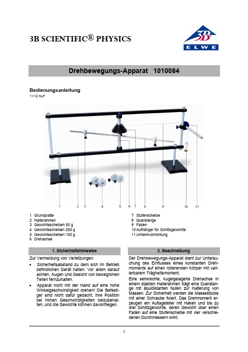
3B SCIENTIFIC ® PHYSICSDrehbewegungs-Apparat 1010084Bedienungsanleitung11/12 ALF1 Grundplatte2 Halterahmen3 Gewichtsscheiben 50 g4 Gewichtsscheiben 200 g5 Gewichtsscheiben 100 g6 Drehachse7 Stufenscheibe 8 Querstange 9 Faden10 Aufhänger für Schlitzgewichte 11 Umlenkvorrichtung1. SicherheitshinweiseZur Vermeidung von Verletzungen:• Sicherheitsabstand zu dem sich im Betriebbefindlichen Gerät halten. Vor allem darauf achten, Augen und Gesicht von beweglichen Teilen fernzuhalten. • Apparat nicht mit der Hand auf eine hoheWinkelgeschwindigkeit drehen! Die Befesti-ger sind nicht dafür gedacht, ihre Position bei hohen Geschwindigkeiten beizubehal-ten, und die Gewichte können davonfliegen.2. BeschreibungDer Drehbewegungs-Apparat dient zur Untersu-chung des Einflusses eines konstanten Dreh-moments auf einen rotierenden Körper mit vari-ierbarem Trägheitsmoment.Eine senkrechte, kugelgelagerte Drehachse in einem stabilen Halterahmen trägt eine Ouerstan-ge mit äquidistanten Nuten zur Halterung von Massen. Zur Sicherheit werden die Massestücke mit einer Schraube fixiert. Das Drehmoment er-zeugen ein Auflageteller mit Haken und bis zu drei Schlitzgewichte, deren Gewicht über einen Faden auf eine Stufenscheibe mit vier verschie-denen Durchmessern wirkt.3. Technische Daten Ouerstange: 600 mm x Ø 8 mm Nutabstand: 40 mmGewichtscheiben: 2x 50 g, 2x 100 g,2x 200gDurchmesser Stufenrolle: 30 mm, 45 mm,60 mm, 75 mmGesamtmasse: 7 kg4. Zusätzlich erforderlich1 Maßstab, 1 m1000742 2 Mechanische Stoppuhr, 15 min 10033695. Experimentierbeispiele5.1 Bestimmung der Winkelbeschleunigung α • Massen auf die Querstange laden und mitSchrauben sichern, Faden einfädeln und um die Stufenscheibe wickeln, Faden über Um-lenkvorrichtung führen und aufwickeln, mit Gewichthänger verbinden, Faden senkrecht zur Stufenscheibe halten. Gewichthänger festhalten. • Zwei Studenten halten sich mit Stoppuhrenbereit. • Gewichthänger loslassen.• Ein Student notiert die Zeit zwischen demLoslassen des Gewichthängers und seinem Auftreffen auf dem Boden. • Sobald die Masse den Boden berührt, notiertder zweite Student die Zeit, die die Querstan-ge benötigt, um zwei Umdrehungen auszufüh-ren. Sicherstellen, dass die Messung gemacht wird, bevor der Apparat aufgrund von Reibung zu langsam wird. • Winkelgeschwindigkeit ω der Querstange inRadianten/Sekunde berechnen und dabei nicht vergessen, dass eine Drehung 2π Radi-anten darstellt. •Die Winkelbeschleunigung erhält man aus der Gleichung: tΔωΔ=αΔω ist der für die Schlusswinkelgeschwindigkeit berechnete Wert (die Anfangsgeschwindigkeit betrug Null) und Δt ist die Zeit, die die Masse be-nötigte, um auf den Boden zu fallen.• Messungen mehrere Male wiederholen unddie Ergebnisse mitteln.• Experimente mit verschiedenen Antriebsmas-sen, Massen auf der Stange und Position derMasse auf der Stange wiederholen. Auswir-kungen auf die Winkelgeschwindigkeit verglei-chen. 5.2 Bestimmung des Drehmoments M Das Drehmoment kann theoretisch und experi-mentell bestimmt und dann verglichen werden. Das theoretische Drehmoment erhält man aus der Gleichung: θ⋅⋅=sin F r M90=θ weil der Faden senkrecht zum Radius des Apparates verläuft. r ist der Radius der Stu-fenscheibe, g m F ⋅=, wobei m die Summe der Schlitzgewichte mit Aufhänger ist und g die Fall-beschleunigung 281,9smg =. Folglich erhältman das theoretische Drehmoment aus der Gleichung:g m r M ⋅⋅=• Zur experimentellen Ermittlung den gleichenVersuchsaufbau verwenden wie in 5.1. •Dazu zuerst die Winkelbeschleunigung mittels der in Abschnitt 5.1 beschriebenen Methoden bestimmen.• Trägheitsmoment J durch das Messen derAbstände zu den Massen auf der Querstange und unter Verwendung der folgenden Formel berechnen:22tan 121R M L M J Massen ge S +=M Stange = Masse der Querstange L = Länge der QuerstangeM Massen = Massen der beiden Gewichtschei-benR = Abstand Gewichtscheibe - Drehachse • Zur Ermittlung des Drehmoments die Winkel-beschleunigung mit dem Trägheitsmoment multiplizieren.α⋅=J M• Änderung des Drehmoments nach Veränderndes Stufenscheibenradius und Variieren der Antriebsmassen bestimmen.5.3 Bestimmung des Trägheitsmoments J • Abstand von der Gewichtscheibe zur Dreh-achse messen. •Winkelbeschleunigung wie in 5.1 bestimmen. • Theoretisches Drehmoment wie in 5.2 be-rechnen.3B Scientific GmbH ▪ Rudorffweg 8 ▪ 21031 Hamburg ▪ Deutschland ▪ Technische Änderungen vorbehalten • Das Trägheitsmoment erhält man aus derGleichung:α=M J •Experiment wiederholen, dabei Masse auf der Querstange gleich belassen und Abstand ver-ändern.• Trägheitsmoment in Abhängigkeit vom Ab-stand grafisch darstellen. • Experiment mit gleichem Abstand aber unter-schiedlicher Masse wiederholen. • Trägheitsmoment in Abhängigkeit von derMasse grafisch darstellen.Das Trägheitsmoment verändert sich gemäß folgender Gleichung: 2R M J ⋅=。
Festo EHMD-40-RE 旋转夹具模块操作手册说明书

1适用文件2安全2.1一般安全注意事项–仅在原装状态下使用产品,请勿擅自进行改动。
–请仅在技术状态完好的情况下使用本产品。
–请注意产品上的各种标识。
–在阴凉、干燥、防紫外线、防腐蚀的环境中存放本产品。
存放时间不可过长。
–在产品上作业前:关断电源,并做好防重启保护。
–遵守紧固扭矩。
如果没有特别说明,则公差为 ±20%。
2.2按规定使用按照规定,本产品用于抓取、夹持和旋转工作负载,例如工件。
2.3可预见的错误使用不得在“打开”运动方向上抓取工作负载。
插图 1:2.4专业人员的资质关于产品的一切工作仅允许由具备资质的专业人员进行,这些专业人员对工作进行评估并识别出危险。
专业人员拥有处理电气气动控制技术的知识和经验。
3详细信息–附件 è/catalogue。
4产品概况4.1功能11插图 2:旋转和抓取作用原理45插图 3:通过弹簧挠度调整抓取力本产品是一种组合式旋转模块和抓取模块。
–电动旋转驱动器 EHMD-...-RE:步进电机的旋转运动通过电机轴直接传递给抓手,并且可以自由定位。
步进电机的增量式编码器可用于闭环控制模式,并且抓手每转一圈就会输出一个零脉冲以供参考。
编码器的零脉冲 ZP 和抓手的纵轴在出厂时与安装面平行对齐。
–电动抓手驱动器 EHMD-...-GE/-GE-16:步进电机的旋转运动通过一个机构传递给夹爪,并且可以自由定位。
步进电机的增量式编码器可用于闭环控制模式。
对于带有扭矩限制功能的伺服驱动器,可以在闭环控制模式中产生定义的抓取力。
对于不带扭矩控制功能的伺服驱动器,可以在定位模式下利用抓手驱动器中的弹簧产生定义的抓取力。
抓手指与工件接触后,抓手驱动器继续移动一段距离 s force,同时张紧弹簧。
如果电源中断,抓取力会下降至剩余抓取力。
–气动抓手驱动器 EHMD-…-GP:气缸的直线运动通过一个机构传递到夹爪。
气缸上的两个位置可以通过接近开关进行监控。
如果气源故障,则无法保持抓取力。
Festo EHMD 旋转抓取模块说明书

Rotary gripper modules EHMD2d Internet: /catalogue/...Subject to change – 2023/04Rotary gripper modules EHMDKey featuresAt a glance• The rotary gripper module is a compact module for handling small parts.• The rotary motion is generated by a stepper motor.• The gripping motion is generated either electrically via a stepper motor or pneumatically via a cylinder.•The gripper can grip in force mode when combined with the servo drive CMMT-ST. This enables flexible gripping.Applications:• Pick & place small parts from trays and tablets • Fitting and removing cover caps on vials• The servo drive CMMT-ST is a closed-loop and open-loop position controller • Monitoring of freely defined positions and torque ranges • Easy activation via:– I/O interface – IO-Link or I-Port – Modbus TCP – EtherCAT – PROFINET – EtherNet/IPEverything from a single sourceRotary module EHMD a page 5Gripper jaw blanks BUB-HGPT a page 23Servo drive CMMT-ST a page 24FCT software – Festo Configuration ToolSoftware platform for electric drives from Festo (a /sp/fct)• All drives in a system can be managed and saved in a common project• Project and data management for all supported types of equipment • Easy to use thanks to graphically supported parameter entry• Universal mode of operation for all drives• Work offline at your desk or online at the machineEtherCAT ®, PROFINET ® and EtherNet/IP ® are registered trademarks of their respective trademark holders in certain countries.32023/04 – Subject to changed Internet: /catalogue/...Rotary gripper modules EHMDKey featuresThe technology in detail RotationClosed-loop controlOpen-loop control• Makes it possible to control the motor torque via the motor current, so the torque can be limited when screwing on a cover cap • No step loss is possible in the event of overload• It is possible to use the entire output torque of the motor • The motor is actuated in microstep operation with a constant, defined phase current• Reduction of the holding current is required to prevent overheating • A torque reserve is required to prevent step lossesHoming• The encoder zero pulse can be used to home the axis of rotation • One zero pulse per revolution• Defined angular orientation based on this zero pulse GrippingClosed-loop controlOpen-loop control • Makes it possible to control the motor torque via the motor current• The gripping force of the gripper can be set by a limited driving torque of the lead screw• The motor is actuated in microstep operation with a constant, defined phase current• Reduction of the holding current is required to prevent overheating• The gripper drive is spring-mounted for force setting, so that defined gripping forces can be set in positioning modeHoming• Gripper motor has an incremental encoder. No limit switch is present • In the opening direction, homing must be to a stopCombinations comprising mini slides EGSC-BS, EGSL and electric slide EGSK With mini slide EGSC-BS-25/32With mini slide EGSL-BS-35/45With electric slide EGSK-20/26Rotary gripper modules EHMDKey featuresApplication exampleFitting and removing cover caps on vialsScrewing cover caps onto vials and removing them• Mini slide EGSC-BS retracted• Mounting EHAM-E20• Mini slide EGSC-BS extends• Rotary gripper module EHMD gripsthe cap• Rotary gripper module EHMD turnsand removes the cap from the vial• The mounting EHAM-E20 takes onthe Z-compensation without theneed to move the mini slide (Z-axis)• Once the cap has been removed,the mini slide EGSC-BS retracts• The Z-compensation moves backinto the lower end position due tothe weight4d Internet: /catalogue/...Subject to change – 2023/04Rotary gripper modules EHMD Type codes5 2023/04 – Subject to change d Internet: /catalogue/...6d Internet: /catalogue/...Subject to change – 2023/04Rotary gripper modules EHMDPeripherals overviewEHMD-40-RE-GE – Electric grippingH- -NoteThe gripper is only intended as an external gripper (in the closing direction).72023/04 – Subject to changed Internet: /catalogue/...Rotary gripper modules EHMDPeripherals overviewEHMD-40-RE-GP – Pneumatic grippingH- -NoteThe gripper is only intended as an external gripper (in the closing direction).8d Internet: /catalogue/...Subject to change – 2023/04Rotary gripper modules EHMDData sheet-O- Output torque0.3 Nm -Y- Rotation angleInfinite -T-Total stroke32 mmActuation via:• Servo drive CMMT-ST• Controller for stepper motors with encoder input1) Rated load = gripper fingers + payloadRotary gripper modules EHMD Data sheetH--Note1) In the event of a power failure, a residual gripping force (gripping force back-up) is ensured by the mechanical design. However, the maximum grippingforce cannot be maintained.92023/04 – Subject to change d Internet: /catalogue/...10d Internet: /catalogue/...Subject to change – 2023/04Rotary gripper modules EHMDData sheet1)Corrosion resistance class CRC 1 to Festo standard FN 940070Low corrosion stress. Dry indoor application or transport and storage protection. Also applies to parts behind coverings, in the non-visible interior area, and parts which are covered in the application (e.g. drive trunnions).2)For information about the area of use, see the EC declaration of conformity at: /sp d Certificates.If the devices are subject to usage restrictions in residential, commercial or light-industrial environments, further measures for the reduction of the emitted interference may be necessary.3)Additional information: /sp d Certificates.Static characteristic load values at the gripper jawsThe indicated permissible forces and torques apply to a single gripper jaw. They include the lever arm, additional weight forces created by the workpiece or exter-nal gripper fingers and acceleration forces during movement. The zero coordinate line (gripper jaw guide) must be taken into consideration for the calculation of torques.Graphs for rotationTorque M as a function of rotational speed n Angular acceleration as a function of moment of inertia JClosed-loop controlOpen-loop controlGraphs for gripping, pneumaticGripping force F as a function of lever arm x and operating pressure dd = 8 bard = 6 bard = 4 bard = 1.5 barData sheetGraphs for electric gripping with CMMT-STGripping force F as a function of lever arm x and force specificationEven if the workpiece size is not known, it is possible to close the gripper with a defined gripping force by limiting the torque. With the CMMT-ST, the force mode can be used to close the gripper. The force setpoint is specified as a percentage value and corresponds to the motor current in relation to the nominal current.EHMD-...-GEEHMD-...-GE-16100%75%50%30%For EHMD-...-GE-16:The characteristic curves show typical gripping forces in the new state. Depending on the function, these may fluctuate as a result of internal friction.Graphs for electric gripping with motor controller (without torque control)Gripping force F as a function of lever arm x and additional pathIf the workpiece size is known, a defined gripping force can be achieved by the deflection of the gripper drive. Here, the gripper continues to be closed along a specific path once it is touching the workpiece. The gripper fingers then stay where they are while the drive continues to move and the spring is tensioned.EHMD-...-GEEHMD-...-GE-160.7 mm 0.6 mm 0.5 mm 0.4 mm 0.2 mm2 mm 1.5 mm 1 mm 0.5 mmGripping force F as a function of velocity vRequirement:• Servo drive CMMT-ST in force mode• Ambient temperature = 25°C20%30%40%50%60%70%80%90%100%Data sheet Pin allocationData sheetData sheetAccessoriesMounting EHAM-E20-40-Z Mounting position: vertical Material:Wrought aluminium alloy RoHS-compliantContains paint-wetting impairmentsubstancesMounting option via dovetail mounting.The mounting compensates for the thread pitch when turning (fitting/removing)cover caps on vials without needing additional movement of the Z-axis.(Z-compensation = 12 mm)212023/04 – Subject to changed Internet: /catalogue/...Rotary gripper modules EHMDAccessoriesMounting EHAM-E20-40 Mounting position: Any Material:Wrought aluminium alloyRoHS-compliantContains paint-wetting impairment substancesRigid mounting option via dovetail mounting.22d Internet: /catalogue/...Subject to change – 2023/04Rotary gripper modules EHMDAccessoriesMounting EHAM-E20-40-E ...Mounting position: Any Material:Wrought aluminium alloyRoHS-compliantContains paint-wetting impairment substances For attaching the mountings to the Z-axes:• Mini slide EGSC-BS-25/32• Mini slide EGSL-BS-35/45• Electric slide EGSK-20/261) Automatic Z-stroke compensation.232023/04 – Subject to changed Internet: /catalogue/...Rotary gripper modules EHMDAccessoriesGripper jaw blank BUB-HGPT (2 included in the scope of delivery)Not included in the scope of delivery of the rotary gripper module.Material:Aluminium Not permitted for EHMD-40-RE-GE-161) Tolerance for centring hole ±0.02 mmTolerance for through-hole ±0.1 mmRotary gripper modules EHMDAccessories24d Internet: /catalogue/...Subject to change – 2023/04252023/04 – Subject to changed Internet: /catalogue/...Rotary gripper modules EHMDAccessories1) Packaging unitFesto - Your Partner in AutomationConnect with us/socialmedia 1Festo Inc.2Festo Pneumatic 3Festo Corporation 4Regional Service Center 5300 Explorer DriveMississauga, ON L4W 5G4CanadaAv. Ceylán 3,Col. Tequesquináhuac 54020 Tlalnepantla, Estado de México1377 Motor Parkway Suite 310Islandia, NY 117497777 Columbia Road Mason, OH 45040Festo Customer Interaction CenterTel:187****3786Fax:187****3786Email:*****************************Multinational Contact Center 01 800 337 8669***********************Festo Customer Interaction Center180****3786180****3786*****************************S u b j e c t t o c h a n g e。
Festo EHMB旋转提升模块数据表说明书

Rotary lifting modules EHMB, electric2d Internet: /catalogue/...Subject to change – 2022/09Rotary lifting modules EHMB, electricCharacteristicsAt a glanceThe rotary lifting module EHMB combines rotary and linear motion in one compact unit. The rotation motion is always transferred via a toothed belt to a hollow shaft by an electric motor while the linear motion is generated either by a pneumatic cylinder DSBC or an electric cylinder ESBF . Both movements act on the output flange.Cables and tubing can be easily routed to the front unit of the rotary lifting module through the large hollow shaft.The movement range can also be sensed using proximity switches at the rotary unit and the cylinder.Advantages:• Large hollow axis • Stable bearing• Various motors and cylinders ena-ble the performance to be adapted easily to the applicationThe technology in detail[1] Stop nut[2] Grooved shaft guide[3] Through-hole for mounting[4] Mounting threads/mounting holes[5] Output flange with centring and threaded holes for payload [6] Drive shaft for rotation [7] Cylinder holder[8]Rod eye and connecting bolt for linear motionFlexible connectionO topU underneath R = right V = front L = left H rear• The rotary lifting module EHMB can be mounted on 4 sides:– On the right or left of the housing (L, R)– On the front cover (V)– Underneath the housing (U)• The cylinder holder can be mounted on 3 sides:– On the right or left of the housing (L, R)– On the front, after removing the front cover (V)• The side where the cylinder holder is mounted cannot be used for mounting the rotary lifting module• A pneumatic standards-based cylinder DSBC or an electric cylinder ESBF can beattached to the cylinder holder. (These cylinders must be ordered separately)Rotary lifting modules EHMB, electric CharacteristicsComplete system consisting of rotary lifting module, motor and axial kitRotary lifting module aPage 6[1] Electric cylinder ESBF, alternatively standards-based cylinder DSBC1)[2] Protective conduit fitting1)[3] Shock absorber1)[4] Shock absorber retainer1)[5] Sensor bracket[6] Proximity switch SIEN1)[8] Motor for rotation1)1) These parts must be ordered separately as accessories.Motors aPage 17Servo motor EMME-AS, EMMT-ASStepper motor EMMS-STIntegrated drive EMCAH--NoteA range of specially matchedcomplete solutions is available forthe rotary lifting module EHMB andmotors.Motor controllers Data sheets aInternet: motor controllerServo motor controller CMMP-ASStepper motor controller CMMT-STMotor mounting kit a Page 17 Axial kitParallel kitComplete kits are available for bothparallel and axial motor mounting.3 2022/09 – Subject to change d Internet: /catalogue/...Rotary lifting modules EHMB, electricPeripherals overviewPeripherals overview4d Internet: /catalogue/...Subject to change – 2022/09Rotary lifting modules EHMB, electric Peripherals overview and type codes-NoteH-When routing electrical cables or compressed air tubing through the hollowshaft of the grooved shaft guide, the rotation angle of the EHMB must be limitedto a rotation angle appropriate to the cables or compressed air tubing.Infinite rotation damages cables and tubingType codes5 2022/09 – Subject to change d Internet: /catalogue/...Rotary lifting modules EHMB, electric Data sheet-N- Size20, 25, 32H--NoteAll values are based on a roomtemperature of 23°C.1) When the travel profile remains the same. The specifications apply only when the motor is directly mounted. If a gear unit is also installed, the repetition accuracy will be different2) Dependent on the encoder resolutionH--NoteThe connection between the drive forthe linear motion and the EHMB isnot backlash-free.1) Output torque minus friction is dependent on rotational speed2) At maximum rotational speed3) With symmetrical and non-eccentric configuration6d Internet: /catalogue/...Subject to change – 2022/0972022/09 – Subject to changed Internet: /catalogue/...Rotary lifting modules EHMB, electricData sheet1) These values specify the upper limit independently of what is determined using the inertia factor.2) The inertia factor represents the maximum controllable ratio between the inertia of the load and the intrinsic inertia of the motor with brake.Example:Rotary lifting module EHMB-20 a transmission ratio i = 4.5Motor EMME-AS-40-S with brake a intrinsic inertia 0.055 kgcm 2Gear unit EMGA-40-P-G3-40 a transmission ratio i = 3Limit for inertia of the load (+ intrinsic inertia) on output side:0.055 kgcm 2 x 45 x 32 x 4.52 = 451 kgcm2MaterialsSectional view123458d Internet: /catalogue/...Subject to change – 2022/09Rotary lifting modules EHMB, electricData sheetMaximum radial and axial force Fy/Fz at the output shaft as a function of distance x/z If the rotary module is simultaneously subjected to several forces, the follow-ing equation must be satisfied in addi -tion to the maximum loads indicatedbelow.F 1 = dynamic value F 2 = maximum valueMax. radial force Fy, dynamicMax. axial force Fx, dynamic, pushing and pullingEHMB-20EHMB-25EHMB-32|FF xx1|FF xx2+|FF yy 1|FF yy2+|FF zz1|FF zz2≤192022/09 – Subject to changed Internet: /catalogue/...Rotary lifting modules EHMB, electricData sheetDeflection f as a function of transverse load F and stroke l The following graphs show the deflec -tion f of the rotary lifting module underradial forces and with two strokes.FEHMB-20EHMB-25f [mm]F [N ]0.20.40.60.81 1.2 1.4 1.6 1.820100200300400500600f [mm]F [N ]0.20.40.60.811.21.41.62004006008000EHMB-32f [mm]F [N ]0.20.40.60.811.21.4200400600800100012000l = 10 mm l = 200 mm10d Internet: /catalogue/...Subject to change – 2022/09Rotary lifting modules EHMB, electricData sheetMax. velocity v as a function of payload m, in combination with the pneumatic standards-based cylinder DSBCMounting position:EHMB-20EHMB-25EHMB-32, with one shock absorber EHMB-32, with two shock absorbersPositioning time t as a function of the rotation angleáSize 20Example with servo motor EMMS-ASα[°]t [s ]45901351802252703153600.10.20.30.4Permissible rangeTypical operating range, depending on motor size and inertia of the load Non-viable rangeExample with stepper motor EMMS-STα[°]t [s ]45901351802252703153600.10.20.30.40.50Permissible rangeTypical operating range, depending on motor size and inertia of the load Non-viable rangePositioning time t as a function of the rotation angle áSize 25Example with servo motor EMMS-ASα[°]t [s ]45901351802252703153600.10.20.30.40.5Permissible rangeTypical operating range, depending on motor size and inertia of the load Non-viable rangeExample with stepper motor EMMS-STα[°]t [s ]45901351802252703153600.10.20.30.40.50Permissible rangeTypical operating range, depending on motor size and inertia of the load Non-viable rangePositioning time t as a function of the rotation angleáSize 32Example with servo motor EMMS-ASα[°]t [s ]45901351802252703153600.10.20.30.40.50.6Permissible rangeTypical operating range, depending on motor size and inertia of the load Non-viable rangeExample with stepper motor EMMS-STα[°]t [s ]45901351802252703153600.10.20.30.40.50.60.70.80.9Permissible rangeTypical operating range, depending on motor size and inertia of the load Non-viable range1) Tolerance for centring hole ±0.02 mmTolerance for thread ±0.1 mm-NoteH-2) The diameter can be reduced using a centring ring (included in the scope of delivery of the EHMB).Cylinder connection for linear motion Ordering data1) Ordering data a Internet: esbfMotor connection for rotary motionPermissible axis/motor combinations with axial kit – Without gear unit Data sheets a Internet: eamm-a1) The input torque must not exceed the maximum permissible transferable torque of the axial kit.-NoteH-Note the maximum permissibledriving torque of the EHMB.The motor current may need to belimited.Motor connection for rotary motionPermissible axis/motor combinations with axial kit – Without gear unit Data sheets a Internet: eamm-a1) The input torque must not exceed the maximum permissible transferable torque of the axial kit.-NoteH-Note the maximum permissibledriving torque of the EHMB.The motor current may need to belimited.Motor connection for rotary motionPermissible axis/motor combinations with axial kit – With gear unit Data sheets a Internet: eamm-a1) The input torque must not exceed the maximum permissible transferable torque of the axial kit.-NoteH-Note the maximum permissibledriving torque of the EHMB.The motor current may need to belimited.Permissible axis/motor combinations with axial kit – With gear unit Data sheets a Internet: eamm-a1) The input torque must not exceed the maximum permissible transferable torque of the axial kit.2) The axial kit can be retrofitted from IP40 to IP65 with the help of a seal set EADS-F. Additional information a eamm-a-NoteH-Note the maximum permissibledriving torque of the EHMB.The motor current may need to belimited.Rotary lifting modules EHMB, electric AccessoriesPermissible axis/motor combinations with axial kit – With gear unit Data sheets a Internet: eamm-a1) The input torque must not exceed the maximum permissible transferable torque of the axial kit.2) The axial kit can be retrofitted from IP40 to IP65 with the help of a seal set EADS-F. Additional information a eamm-a-NoteH-Note the maximum permissibledriving torque of the EHMB.The motor current may need to belimited.21 2022/09 – Subject to change d Internet: /catalogue/...Rotary lifting modules EHMB, electric AccessoriesRod eye SGSScope of delivery:1 rod eye, 1 hex nut to DIN 439 Material:Galvanised steel1) Packaging unit22d Internet: /catalogue/...Subject to change – 2022/09232022/09 – Subject to changed Internet: /catalogue/...Rotary lifting modules EHMB, electricAccessories1) Packaging unit2) a Dimensional drawing on page 14H- -NoteThe retaining bracket for the proximi-ty switch SIEN is included in the scope of delivery of the rotary lifting module.Rotary lifting modules EHMB, electric AccessoriesAdapter kit EHAM Material:Wrought aluminium alloyFree of copper and PTFERoHS-compliantH--NoteThe kit includes the individualmounting interface as well as thenecessary mounting material.1) Corrosion resistance class CRC 2 to Festo standard FN 940070Moderate corrosion stress. Indoor applications in which condensation can occur. External visible parts with primarily decorative surface requirements which are in direct contact with a normal industrial environment.24d Internet: /catalogue/...Subject to change – 2022/09Festo - Your Partner in AutomationConnect with us/socialmedia 1Festo Inc.2Festo Pneumatic 3Festo Corporation 4Regional Service Center 5300 Explorer DriveMississauga, ON L4W 5G4CanadaAv. Ceylán 3,Col. Tequesquináhuac 54020 Tlalnepantla, Estado de México1377 Motor Parkway Suite 310Islandia, NY 117497777 Columbia Road Mason, OH 45040Festo Customer Interaction CenterTel:187****3786Fax:187****3786Email:*****************************Multinational Contact Center 01 800 337 8669***********************Festo Customer Interaction Center180****3786180****3786*****************************S u b j e c t t o c h a n g e。
Festo EHMD-GE 组合式旋转和抓取模块操作手册说明书
原版操作手册的译本1关于本文件适用文件产品所有相关文档è /pk。
名称目录应用注意事项关于连接和调试的应用示例Tab. 1 有关旋转抓取模块的文件2安全2.1一般安全提示–仅在原装状态下使用产品,请勿擅自进行改动。
–请仅在技术状态完好的情况下使用本产品。
–请注意产品上的各种标识。
–在阴凉、干燥、防紫外线、防腐蚀的环境中存放本产品。
确保短期存放。
–装配、安装和维修保养工作:关闭电源,确保不会重新启动。
–遵守拧紧力矩。
如果没有特别说明,则公差为 ± 20 %。
2.2按规定使用按照规定,本产品用于抓取、夹持和旋转工作负载(工件)。
2.3可预见的错误使用不可通过位于内部的作用点抓取。
EHMD-...-GE:在常规工作状态中,不可沿打开方向碰到挡块。
2.4专业人员的资质仅允许由具备资质的专业人员安装、调试、保养和拆卸本产品。
专业人员必须掌握电气和气动控制系统安装的专业知识。
3详细信息–附件è /catalogue。
4服务若有技术问题,请联系 Festo 公司在您所在地的联系人è 。
5产品概览5.1功能原理Fig. 1本产品是一种组合式旋转和抓取模块。
抓取时沿夹爪的闭合方向进行(外部作用点)。
根据型式,可通过电动(EHMD-...-GE) 或气动 (EHMD-...-GP) 方式操作平行抓手。
两种型式的平行抓手均可通过电动旋转轴持续旋转。
5.1.1夹持力保护EHMD-...-GP:无夹持力保护。
只能通过额外的措施(例如不间断的压缩空气供应)来确保安全夹持力。
EHMD-...-GE:带夹持力保护。
电源中断时,可通过机械设计确保最小的夹持力。
但无法保持最大夹持力。
5.2产品配置1用于夹持功能的步进电机(安装于外壳中)2高温表面警告3用于夹持功能的气缸4可旋转夹持模块5夹爪Fig. 26安装6.1准备气爪指气爪指不包含在供货范围内。
坯件可作为附件在以下网址购买è/catalogue。
cascade 160G 旋转器 规格表说明书
160G ROTATOR APPLICATIONSThe 160G Rotator gives your driver the ability to quickly dump or inverta load easily and accurately. Cascade rotators are widely used in foodprocessing, automotive, chemical processing, recycling operations,casting operations, and general manufacturing – anywhere it is necessaryto dump bins or tote boxes.FEATURES■Cascade’s dual gear drive and ring gear design are proven toprovide superior durability and enable driver to quickly invert load.■L arge visibility window gives the driver an excellent viewof the fork tips. Center seal locks out contamination.■G ood torque specifications ensure smooth, positive rotation ofthe load.■M any fork bar widths are available to suit a wide variety ofapplications.■R otators may be ordered with forks or with fork bars only.■E asy conversion of mounting hooks when changing truck sizes.OPTIONS■S pecial Fork Sizes and Configurations.■H ydraulic Bin Retainer is custom designed to clamp on top of bin tohold bin in place while rotating. Typically used when bin does nothave fork pockets.■M echanical Bin Retainer is designed to retain lightweight bins.■Side Stabilizers help retain the load during rotation.■180° stop group.■ERC – Electronic Rotation Control.■Fork restraints to keep forks from twisting from side to side.■Foundry options to protect against molten metal splash andhigh heat.contaminationCascade Corporation • PO Box 20187 • Portland, OR 97294-0187 • USA • 800 CASCADE (227.2233) • Tel 503.669.6257 • Fax 800.693.3768 • Fax 503.669.6367Cascade Canada Ltd. • 5570 Timberlea Blvd. • Mississauga, Ontario L4W 4M6 • Canada • 800.380.2272 • Tel 905.629.7777 • Fax 905.629.7785Form 6881907 US 05/17Cascade is a registered trademark of Cascade Corporation. © Cascade Corporation 2016. All rights reserved.160G ROTATORC a t a l o g O r d e r N o .160G-RRB-10C160G-RRB-20C160G-RRB-30C160G-RRB-14C160G-RRB-24C160G-RRB-34C160G-RRB-16C160G-RRB-26C160G-RRB-36C160G-RRB-17C160G-RRB-27C 160G-RRB-37C C a p a c i t y @ 24" (600 m m ) L o a d C e n t e rF o r k L e n g t h M a x i m u m O T O F o r k S p r e a dM t g .C l a s s M t g .A n g l eU p p e r H o o k W i d t h O T OW e i g h t E f f e c t i v e T h i c k n e s sH o r i z o n t a l C t r .o f G r a v i t yV e r t i c a l C t r .o f G r a v i t yO v e r a l l W i d t hl bs k g A Bl bs k g E T H CG V CG C w /o Forks 49"I V 0°43.9"1,9078679.0"4.8"16.9"51.3" w /o Forks 61"I V 0°43.9"2,0289229.0"5.0"16.6"63.3" w /o Forks 73"I V 0°43.9"2,1489769.0"5.2"16.4"75.3"16,0007,27048"49"I V 0°43.9"2,5551,16111.8"8.5"13.9"51.3"16,0007,27048"61"I V 0°43.9"2,6631,21111.8"8.5"13.9"63.3"16,0007,27048"73"I V 0°43.9"2,7831,26511.8"8.5"13.8"75.3"16,0007,27060"49"I V 0°43.9"2,6521,20511.8"10.2"13.2"51.3"16,0007,27060"61"I V 0°43.9"2,7731,26011.8"10.1"13.2"63.3"16,0007,27060"73"I V 0°43.9"2,8931,31511.8"10.0"13.2"75.3"16,0007,27072"49"I V 0°43.9"2,7641,25611.8"12.3"12.5"51.3"16,0007,27072"61"I V 0°43.9"2,8851,31111.8"12.1"12.5"63.3"16,0007,27072"73"I V 0°43.9"3,0051,36611.8"12.0"12.5"75.3"360º RotationCapacity at 24 in Load Center (600 mm) – Fork Size (W x T)Model Class 5 x 1.75 in 122 x 45 mm 5 x 2 in 122 x 50mm 6 x 2 in 150 x 50 mm 6 x 2.5in 150 x 65 mm 7 x 2in 180 x 50 mm 8 x 3 in 75 x 200mm 160GIV6,460 lbs2,930 kg8,075 lbs3,663 kg10,200 lbs4,626 kg16,000 lbs7,257 kg13,150 lbs5,964 kg——BCET AVCGHCG2.8"23.5"44"29.4"4.9"23.7"34.3"5.9"LC rotation Class IV Fork BarS ee Capacity Chart below for capacities with various fork sizes. Capacity is shown with forks.HYDRAULIC FLOW, PRESSURE & ROTATOR SPECIFICATIONSModel MaximumAttachment WorkingPressure(psi)MaximumDeliverable Pressure (psi/bar)RotatorCircuit Pressure Protected Yes/No?Attachment Number of Functions Min-Rec-Max Function 1(gpm)AttachmentNumber of Funtions Truck AuxiliaryValves Required RPM @ Flow (gpm)Torque in/lbs. @ 2,300 psi160G 5002,300/160No 110 - 20 - 2011 3.6 @ 20160,000Optional motors providing faster rotation available. Reduced torque will result. Optional motors providing more torque available. Reduced speed will result.Auxiliary pressure protection is required for the rotator section unless theoption was specified at the time of the order. Contact your Cascade representative for details.。
Φ178旋转导向钻井工具机械结构设计 说明书
Φ178旋转导向钻井工具机械结构设计摘要:旋转导向钻井技术是石油工业工程技术领域的关键技术之一,得到了石油钻井工程界的极大关注,发挥着越来越重要的作用,主要应用于水平井、大位移井、超深井、三维多目标井等复杂结构的井作业。
本文综述了旋转导向钻井工具的国内外现状,闸明了在我国发展旋转导向钻井技术的重要性和必要性,介绍了它的工作原理及结构组成,指出了研制该工具的主要技术特点。
调制式旋转导向钻井工具的导向执行机构是靠内外泥浆液压力差驱动的原理来实现的,这是旋转导向钻井工具能否正常工作的关键。
所以,对其液压盘阀分配系统进行分析计算,及其在井下不同工况下所受的力进行分析计算。
分析了旋转导向钻井系统的井下钻井工具系的偏置方式和导向方式,完成了导向执行机构机械部分的设计。
关键词:旋转导向钻井工具;机械结构设计;压力差;Φ178 Rotary Steerable Drilling Tool Mechanical StructureDesignAbstract:In many oil industry engineering filed key technologies,rotary steerable drilling technology is one that has been paid much attention to in recent years and exhibits more and more importance in oil drilling industry, mainly used in horizontal well,extended reach well,ultra-deep well ,3D multi-target well the complex structure of multi-lateral wells in wells operating. This paper reviews the domestic and international drilling tool status, illustrates the development of rotary steerable drilling technology of the importance and necessity to introduce the working principle and its composition, that the development of the main technical features of the tool. Modulated rotary steerable drilling tool driven by the executing agency is the pressure difference between inside and outside the mud fluid-driven principles to achieve, which is whether the drilling tool to work the key. Therefore,its hydraulic disc distribution system analysis and calculation, and its different working conditions in underground analyzing and calculating the force. Analysis of downhole rotary steerable drilling tool drilling system orientation bias way. Complete guide the design of mechanical parts of the implementing agencies.Key words: Rotary steering drilling tool;Mechanical parts design;Pressure difference目录第一章绪论 (1)1.1 本论文研究的目的、价值和意义 (1)1.2 国内外研究状况及趋势 (2)1.2.1 国内旋转导向钻井系统研究与发展现状 (2)1.2.2 国外旋转导向钻井系统研究与发展现状 (3)1.3 毕业设计论文的主要内容 (9)第二章旋转导向钻井装置的方案对比分析 (10)2.1 旋转导向钻井工具的分类 (10)2.2 三种旋转导向钻井系统的结构特征和对比 (10)2.2.1 Auto Trak旋转导向钻井系统 (10)2.2.2 Power Drive旋转导向钻井系统 (11)2.2.3 三种不同旋转导向方式对比 (14)2.3 旋转导向钻井方案的选择 (15)2.4 旋转导向钻井工具工作原理 (15)第三章旋转导向钻井工具机械部分设计 (18)3.1 导向机构的导向原理及组成 (18)3.2 上盘阀高压孔圆弧角的确定 (22)3.3 柱塞的相关计算 (22)3.4 巴掌结构 (23)3.5 盘阀泥浆过流的有效面积计算 (24)3.6 巴掌销钉的强度校核 (26)3.7 挡块上的螺钉强度校核 (26)3.8 盘阀连接螺钉强度校核 (27)3.9 液压盘阀系统的设计 (27)3.9.1 上盘阀的结构设计计算 (27)3.9.2 上盘阀传动轴的校核 (30)3.9.3下盘阀的设计 (31)3.9.4上下盘阀导通时间计算 (32)3.10 盘阀加压弹簧的设计 (34)3.11 工具体的校核 (35)第四章旋转导向钻井工具经济性评价 (38)4.1 旋转导向工具的加工成本 (388)4.2 旋转导向工具的经济效果 (38)第五章结论及展望 (40)5.1 结论 (40)5.2 展望与建议 (40)参考文献 (41)致谢 (43)第一章绪论1.1本论文研究的目的、价值和意义为了节约开发成本和提高石油产量,对那些受地理位置限制或开发后期的油田,通常通过开发深井、超深井和长距离水平井来实现,进而造成复杂结构的井不断增多,这就要加快旋转导向钻井工具研究的步伐。
Festo DHTG 2018-02e 旋转索引表操作指南说明书
enOperating instructions80858602018-02e [8085862]Rotaring indexing tableDHTGDHTG2Festo – DHTG – 2018-02eTranslation of the original instructions DHTG-ENIdentification of hazards and instructions on how to prevent them:DangerImmediate dangers which can lead to death or serious injuriesWarningHazards that can cause death or serious injuriesCautionHazards that can cause minor injuriesOther symbols:NoteMaterial damage or loss of functionRecommendations, tips, references to other documentationEssential or useful accessoriesInformation on environmentally sound usageText designations:Activities that may be carried out in any order1.Activities that should be carried out in the order stated –General listsèResult of an action/References to more detailed informationDHTGFesto – DHTG – 2018-02e English 3English – Rotaring indexing table DHTGTable of contents1Operating elements and connections 4 (2)Function and application 5...................................................3Transport and storage 5.....................................................4Requirements for product use 5...............................................5Installation 6..............................................................5.1Mechanical assembly 6......................................................5.2Installing the pneumatic system 7..............................................5.3Electrical installation 9.......................................................6Commissioning 10.. (7)Operation 12...............................................................8Maintenance and care 13.....................................................9Dismantling and repairs 14...................................................10Accessories 16..............................................................11Troubleshooting 16. (12)Technical data 17............................................................13Characteristic curves 18......................................................DHTG4Festo – DHTG – 2018-02e English1Operating elements and connectionsFor all available product documentation è/pk12356789aJ 461Retaining screw for table bearing 2Threaded and pin hole for adapter 3Through hole for power supply 4Threaded and pin hole for plate5Centring/through hole and thread for fastening6Adjusting screw for setting the cushioning7Threaded hole for sensor for position sensing 8Supply port A and B forclockwise/anti-clockwise rotation 9Supply port C and D for reciprocatingoperation (sealed on delivery)aJ One-way flow control valve for speedregulationFig. 1DHTGFesto – DHTG – 2018-02e English52Function and applicationThe DHTG rotary indexing table is a double-acting rotary drive based on the toothed rack and pinion principle with forced locking (as from size DHTG-140 also with overload protection). When the compressed air ports are pressurised alternately, two toothed rod pistons move backwards and forwards. By means of a pinion, the pistons convert the linear movement into a rotary movement. A second pair of pistons controls the engagement of the pinion in the table gearing and the locking of the holding position. The integrated shock absorber brakes the rotary indexing table in the direction of rotation.Fig. 2The DHTG rotary indexing table is intended for turning the work load by a defined angle into a holding position.3Transport and storageTake the weight of the DHTG into consideration. It weighs up to 25 kg. Ensure the following storage conditions are met:–Short storage times and–Cool, dry, shaded, corrosion-resistant storage locations.4Requirements for product useNoteImproper handling can result in malfunctions.Be sure to always comply with the specifications in this chapter.Compare the maximum values specified in these operating instructions with those of your actual application (e. g. forces, torques, temperatures, masses, speeds).Only compliance with the load limits allows operation of the product in compliance with the relevant safety regulations.Take into consideration the ambient conditions at the location of use. Corrosive environments reduce the service life of the DHTG.Ensure that there is a supply of correctly prepared compressed air.Maintain the selected medium for the complete service life of the product. Example: Always use non-lubricated compressed air. Pressurise your entire system slowly.This will prevent uncontrolled movements from occurring.For slow start-up pressurisation use safety start-up valve type HEL.Comply with the regulations of the trade association, the German Technical Control Board or relevant national regulations.DHTG6Festo – DHTG – 2018-02e EnglishRemove all transport packing such as foils, caps, cartons (except for any sealing elements in the pneumatic connections and holes for the proximity switches). The packing is intended for recycling (except for: oiled paper = other waste).Use the product in its original condition without any unauthorised modifications.Take the tolerance of the tightening torques into account. Unless otherwise specified, the tolerance is ±20 %.5Installation5.1Mechanical assemblyMake sure there is sufficient space for the pneumatic connections, for conversion or for replacing the shock absorber.Fasten the DHTG with four screws and ZBH centring sleeves.Tightening torques è Tab. 1, Tab. 2.Direct mounting from above Size6590140220Screw M4M6M6M8Recess for centring sleeve [mm]7121215[mm]5888Tightening torque [Nm]2.99.99.924Tab. 1Direct mounting from below Size6590140220Screw M5M8M8M10Recess for centring sleeve [mm]7121215Tightening torque [Nm]5.9242447Tab. 2Fig. 3Fig. 4DHTGFesto – DHTG – 2018-02e English 7Fasten the blank plate with 6 screws and 2 centring pins.After fitting, the 6 screw recesses can be sealed with the cover caps supplied (press in until flush).Blank plate mounting Size6590140220ScrewM4M4M6M8Locating hole for centring pin [mm]4456Depth locating hole for centring pin [mm]5888Tightening torque [Nm]2.92.99.924Tab. 35.2Installing the pneumatic systemConnect the pneumatic ports A to D (if applicable remove sealing elements).Clockwise or anti-clockwise rotation 1)Size 6590140220Connection A Unlock and turnConnection BLock and return stroke Connecting thread M5G x Tightening torque1.5 Nm 7 Nm1)Modification è 9 Dismantling and repairsTab. 4Reciprocating operation 1)Size6590140220Connection A Unlock Connection B LockConnection C Clockwise rotation 2)Connection DAnti-clockwise rotation Connecting thread M5G x Tightening torque1.5 Nm 7 Nm1)Separate kit required (Accessories è /catalogue)2)Use external flow control valveTab. 5Fig. 5Fig. 7DHTGAs an example 4 interfaces are shown:Tab. 6NoteIf used in safety relevant applications, additional measures are necessary, e. g. inEurope the standards listed under the EU machine guidelines must be observed.Without additional measures in accordance with statutory minimum requirements, theproduct is not suitable for use in safety-related sections of control systems.8Festo – DHTG – 2018-02e EnglishDHTGFesto – DHTG – 2018-02e English 95.3Electrical installationIf proximity switches are used for position sensing:NoteFaulty switching or damage to the proximity switches due to being screwed in too far. Make sure the proximity switches arescrewed into the thread (U), (V) or (W) up to the following maximum depth.Max. screw-in depth Size6590140220Thread (U), (W)[mm]11.511.513.518.5Thread (V)[mm]19.7141621Tab. 8Screw the proximity switches into the following threaded holes:SensingDirection of rotation of plate Clockwise rotationAnti-clockwise rotation (reciprocating operation/flexible control)Direction of rotation (W)(U)Locking mechanism (V)(V)Piston end position (U)(W)Tab. 9When the DHTG is used with 3-part split (DHTG-140 and DHTG-220):NoteBased on the design, the rotating plate can engage in an intermediate position (corresponding to the 6-index stations).After an emergency stop / overload, make sure that the rotating plate is in the desired position before the system is placed back in operation.If the rotating plate is engaged in an intermediate position, bring the locked rotating plate into the desired position by jerking and twisting it against the overloadprotection.Fig. 8DHTG10Festo – DHTG – 2018-02e English6CommissioningWarningRisk of injury from rotating masses.Make sure nobody can place his/her hand in the positioning range of the DHTG and that no objects lie in its path (e. g. by providing a protective screen).NoteIncorrect functioning due to inaccurate toothed rod position. When the DHTG isexhausted, the resetting force of the shock absorber can push the rotary table out of the end position and into an undefined position.Before each commissioning procedure, pressurise the last pressurised connection:–Connection (B) for clockwise/anti-clockwise rotation–Connection (C) or (D) for reciprocating operation/flexible control.NoteClockwise rotation is controlled internally through the flow control valve aJ .Reciprocating operation must be controlled externally through an additional one-way flow control valve GRLA, Connection (C), Fig. 10 (è /catalogue).Screw the flow control screw aJ :–in completely,–then loosen one rotationSlowly pressurise the complete system with at least 4 bar. Start a test run Tab. 10.Check in a test run at low pulse frequency whether the following modifications are necessary:–Readjustment of the proximity switches–Increase the speed step-by-step by unscrewing the flow-control screw aJ –Set the cushioning.Fig. 10Direction of rotation of plateClockwise/anti-clockwise rotation Reciprocating operation/flexible control 1)Basic position: Connection (B) pressurised è see examples Tab. 11 to Tab. 131.Slowly pressurise connection (A)2.Provide clock pulses for the valve1)Internal flow control in one direction only (if necessary throttle different direction externally)Tab. 10Examples for reciprocating operation/flexible controlClockwise rotation ReactionBasic position: Connection (B) and (D) pressurised1.Pressurise connection (A)Unlock2.Pressurise connection (C)Pulse right3.Pressurise connection (B)Lock4.Pressurise connection (D) (continue with 1.)Return strokeTab. 11Anti-clockwise rotation ReactionBasic position: Connection (B) and (C) pressurised1.Pressurise connection (A)Unlock2.Pressurise connection (D)Pulse left3.Pressurise connection (B)Lock4.Pressurise connection (C) (continue with 1.)Return strokeTab. 122 x clockwise and 2 x anti-clockwise rotation ReactionBasic position: Connection (B) and (D) pressurised1.Pressurise connection (A)Unlock2.Pressurise connection (C)Pulse right 13.Pressurise connection (B)Lock4.Pressurise connection (D)Return stroke5.Pressurise connection (A)Unlock6.Pressurise connection (C)Pulse right 27.Pressurise connection (B)LockDirection of rotation change8.Pressurise connection (A)Unlock9.Pressurise connection (D)Pulse left10.Pressurise connection (B)Lock11.Pressurise connection (C)Return stroke12.Pressurise connection (A)Unlock13.Pressurise connection (D)Return stroke14.Pressurise connection (B) (continue with 1.)LockTab. 13Note the maximum permitted frequencies as a factor of the moment of mass inertia (è Technical specifications).The rotary indexing table must not strike hard against the end stops and the overload protection must not be triggered.End the test run.For setting the cushioning:Loosen the clamping element (K) one rotation.Screw in the adjusting screw 6 until the desired cushioning is achieved. The rotary indexing table must not strike hardagainst the end stops and the overload protection must notbe triggered. The maximum moment of mass inertia mustnot be exceeded.Fig. 11Adjusting screw direction of rotation 6ReactionClockwise1)Cushioning is increased Anti-clockwise Cushioning is reduced1)Screw in the adjusting screw until it is flushTab. 14Tighten the clamping element (K) again.Tightening torqueSize6590140220Width across flats 2.5 2.544Tightening torque[Nm]0.80.8 2.5 2.5Tab. 157OperationWarningRisk of injury from rotating masses.Make sure nobody can place his/her hand inthe positioning range of the DHTG and that noobjects lie in its path (e. g. by providing aprotective screen).Note the moment of mass inertia as a factor of the switching or cycle frequency (è Characteristic curves).–The maximum achievable switching frequency as a factor of the moment of mass inertia can be read in the diagram Switching frequency. The switching time can be calculated from thisby T = 60/f. The response time comprises: Switching time = unlocking, turning, locking and thereturn stroke of the work piston.–The maximum achievable cycle frequency as a factor of the moment of mass inertia can be read in the diagram Cycle frequency. The minimum possible cycle time can be calculated from this by T = 60/f.The actual cycle time is then calculated as follows:Cycle time = switching time + processing time + dwell time.–The processing time results from the time which the relevant customer application requires(e. g. time for removing components, press-in time, etc).–Dwell time may be necessary if the actual cycle time is less than the minimum possible cycle time (calculation example è Catalogue specifications).Note that the viscosity of the shock absorber oil decreases with increasing heat. The shock absorber might therefore strike through if the device is operated for too long a period. If necessary reduce the moment of mass inertia.Avoid the DHTG coming into contact with:–Aggressive media–Grinding dust–Glowing sparks or chips.These will damage the DHTG.8Maintenance and careSwitch off the power supplies:–Operating voltage–Compressed air supply.Cleaning:Only clean the DHTG using a soft cloth.All non-abrasive cleaning agents are permitted.Due to its service life lubrication the DHTG does not require any maintenance.Regular removal of the lubricating grease on the surface of the piston rod will reduce the service life.After a conversion (e. g. to reciprocating operation) lubricate the following components with LUB-E1:–piston, piston chamber, seal, lock, toothed rod, pinion, table bearing, dividing disc.We recommend the mechanical components are lubricated again after every 5 million switching cycles.Check the shock absorbers every 2 million strokes for:–Oil leakage–Hard knocking–Function (shock absorber head must not remain in the retracted end position).Dismantling the shock absorber (è Dismantling and repairs).Replace the shock absorber when it shows one of the following signs of wear, or every 10 million strokes at the latest.Check whether lubrication/testing must be carried out more frequently.This may be necessary in case of:–High temperatures–Excessive dirt–Fat solvent fluids or fumes in the vicinity.9Dismantling and repairsRecommendation: Return the product to our repair service for overhaul.The necessary fine adjustments and tests will then be taken into account.Information about spare parts and aids can be found at: /sparepartsSwitch off the power supplies:–Operating voltage–Compressed airExhaust the system and the product.Replacing the integrated shock absorber:1.Unscrew the flow-control screw aJ.2.Unscrew the fastening screws (M) on the sub-base.ing pliers, remove the retaining ring on the shock absorber.4.Replace the shock absorber.5.Fit the individual parts again in reverse sequence (tightening torque è Tab. 16).Fig. 13Tightening torqueSize6590140220Flow control screw aJ[Nm] 1.5 1.5 5.5 5.5 Fastening screws (M)[Nm] 2.9 2.99.99.9Tab. 16Conversion from clockwise rotation (as supplied) to anti-clockwise rotation:1.Loosen the clamping element (K) of the adjusting screw one rotation.2.Unscrew the adjusting screw 6 a few rotations.3.Unscrew flow control screw aJ and the fastening screws (M) from the sub-base.ing pliers, remove the retaining ring (S) on the shock absorber.5.Fit the following:–the shock absorber with the retaining ring in the adjacent hole–the O-ring (P) / buffer (for DHTG-65) in the adjacent groove–the distance piece (T) in the same hole (distance piece omitted for 2/3 index stations)–the sub-base with the fastening screws and the flow control screw in reverse sequence (tightening torque è Tab. 17).6.Unscrew the fastening screws (N) on the stop plate.7.Unscrew:–both locking screws (O) on the rear of the stop plate to begin with,–then screw them in again into the open holes (tightening torque è Tab. 17).The open holes (R) or (L) in Fig. 14 determine the direction of rotation(Holes (R) open: clockwise rotation).8.Screw the fastening screws (N) on the stop plate again (tightening torque è Tab. 17).The rotary indexing table remains pneumatically controlled as before.9.Screw in the adjusting screw 6 until the desired cushioning is achieved è Fig. 11.10.Tighten the clamping element (K) of the adjusting screw (tightening torque è Tab. 15).Fig. 14Tightening torqueSize6590140220 Flow control screw aJ[Nm] 1.5 1.5 5.5 5.5 Fastening screws (M)[Nm] 2.9 2.99.99.9 Plug screw (O)[Nm]0.5Fastening screws (N)[Nm] 1.5 2.9 5.9 5.9 Tab. 1710AccessoriesNotePlease select the appropriate accessories from our catalogue è /catalogue11TroubleshootingMalfunction Possible cause RemedyRotating plate does not move Overload protection is active Pressurise connection (B) and turnthe plate back against the directionof rotation as far as possible. Doingthis causes the overload protectionand the locking mechanism, ifapplicable, to engage audibly Audible leakage Send DHTG to FestoFlow-control screw closedcompletelyOpen screwRotating plate does not engage End position not reached Unscrew the adjusting screw for theshock absorber until the rotatingplate engagesOverload protection is activeè see aboveToothed disc and pinion stand toothon toothPlease contact Festo s TechnicalHotlineHard metal impact at the end position Adjusting screw for shock absorberunscrewed too farScrew in adjusting screwShock absorber defective Replace shock absorber(è 9 Dismantling and repairs)Hard metallic knocking in the locking mechanism Adjusting screw for shock absorberscrewed in too far (e. g. whenchanging the direction of rotation)Unscrew adjusting screwPlate position incorrect Overload protection engagedincorrectly at 180° (plate offset 30°)Force overload protection and turn until it re-engagesTab. 1812Technical data1)Parallelism of the plate surface relative to the housing support2)Measured on the surface of the plate at the edge of the plate in relation to the housing support3)Measured on the inner diameter of the plate in relation to the housingTab. 1913Characteristic curvesSwitching frequency f as a function of mass moment of inertia J Size 65J [kgm]Size 902Size 140f [1/m i n ]22 indexing stations3 indexing stations4 indexing stations 6 indexing stations 8 indexing stations 12 indexing stations 24 indexing stationsSwitching frequency f as a function of mass moment of inertia J Size 220f [1/m i n ]23 indexing stations4 indexing stations 6 indexing stations 8 indexing stations 12 indexing stations 24 indexing stationsMax. permissible cycle frequency f as a function of mass moment of inertia J Size 65f [1/m i n ]J [kgm 2]Size 90f [1/m i n ]J [kgm 2]2 indexing stations3 indexing stations4 indexing stations 6 indexing stations 8 indexing stations 12 indexing stations 24 indexing stationsMax. permissible cycle frequency f as a function of mass moment of inertia J Size 1402Size 220J [kgm 2]3 indexing stations4 indexing stations 6 indexing stations 8 indexing stations 12 indexing stations 24 indexing stationsDHTGFesto – DHTG – 2018-02e English21Reproduction, distribution or sale of this document or communication of its contents to others without express authorization is prohibited. Offenders will be liable for damages. All rights reserved in the event that a patent, utility model or design patent is registered.Copyright:Festo SE & Co. KGRuiter Straße 8273734 EsslingenGermanyPhone:+49 711 347-0Fax:+49 711 347-2144E-mail:******************************* Internet:。
- 1、下载文档前请自行甄别文档内容的完整性,平台不提供额外的编辑、内容补充、找答案等附加服务。
- 2、"仅部分预览"的文档,不可在线预览部分如存在完整性等问题,可反馈申请退款(可完整预览的文档不适用该条件!)。
- 3、如文档侵犯您的权益,请联系客服反馈,我们会尽快为您处理(人工客服工作时间:9:00-18:30)。
旋转导向操作手册2019-01-12目录第一章旋转导向仪器的简介 (1)第二章旋转导向仪器的原理与参数 (1)第三章旋转导向仪器的作业安全 (3)第四章旋转导向仪器作业流程 (4)第五章 ToolCom NT的设置及工具检测 (6)第六章 TIP的设置 (18)第七章 DownLink 的设置 (25)第八章常见问题处理方法 (29)第一章旋转导向仪器的简介建立在先进闭环循环系统成功应用的基础上,在旋转导向的设计中,运用了最新的随钻测量技术。
这种第三代系统开拓了定向井钻井的新领域,包括双向地质导向和大位移钻井。
该工具可以在旋转钻进过程中实现导向,改变井眼轨迹,并与地面双向通讯。
旋转导向系统,可提供近钻头井斜、方位伽马、电磁波传播电阻率、实时压力和振动测量。
旋转导向服务具有以下几个方面的优势:1.旋转中实现导向:降低摩阻扭矩、实现井眼清洁、更高机械钻速、减少压差卡钻、提高钻头性能、提高井眼质量、节约时间。
2.自动导向控制:精准的水平段垂深控制、降低井眼屈曲。
3.地层评价和压力:精确的地质导向和井眼轨迹控制、电磁波传播电阻率、方位伽马、钻具内、环空和静液压力。
4.双向通讯:多样的随钻测量指令、可调导向(工具面)、可调狗腿度、一趟钻打完井段、适应环境的传输。
第二章旋转导向仪器的原理与参数LWD-O can realize formation oil, gas and water interface and evaluation of geosteering, this feature on a drill collar length to achieve the orientation, gamma, resistivity, borehole pressure and drilling tool vibration measurement functions, and other projects.SpecificationsMaximum Temperature 300°F (150°C)Maximum Rotation Rate 400 rpmDiameter 6.75 in.Min Hole 8.38 in. (21 cm)Max Hole 9.88 in. (25 cm)Weight 3660 lbs (1660 kg)Max Lost Circulation Material 40 ppb=114 kg/m3Dogleg Severity Standard drilling string(With Drill Collar)10°/100 ft (Rotation)16°/100 ft (No rotation)Flexible drilling string assembly(With compression rod)15°/100 ft (Rotation)25°/100 ft (No rotation)Power 300 WVoltage 33 Vdc (± 1 V)ResistivityPhase 0.1 - 3000 ohm-m (2 MHz)0.1 - 1000 ohm-m (4 MHz)Attenuation 0.1 - 500 ohm-m (2 MHz)0.1 - 200 ohm-m (4 MHz)Pressure probeRange 0 - 25000 psiAzimuth moduleProbe Type Tri-axial Accelerometer &Tri-axial Flux GateMTF/GTF 3°Inclination 0° - 180°Azimuth 0° - 360°Tool Surface (M/G) 0° - 360°Dip Angle -90° - +90°Vibration typeProbe Type Axial vibration z-AccelerometerLateral vibration x-y Accelerometer Range 0 to ± 15 gRotating & stick slipProbe Type Two Axis MagnetometerRange 0 to ± 1000 rpmAccuracy ± 1%GR probeTool Type Scintillation Range0-500 APIAccuracy ± 2.5 API/100 APIVertical Resolution 6 in. (15.3 cm)The R otary S teerable S ystem based on advanced closed-loop circulation system on the basis of successful application, using the new MWD technology in the design of RSS. This new system opens up a new field of directional well drilling, including the two-way geosteering drilling and large displacement. The tool can realize direction in the rotary drilling; improve the borehole trajectory and two-way communication with the surface.SpecificationsMaximum Temperature 300°F (150°C)Maximum Pressure 20,000psi (140MPa) (1406kg/cm2) Diameter 6.75 in.Hole Diameter 8.5 in. / 9.5 in. / 9.875 in.Weight 905 lbs (410 kg )Make-Up Length 7.2 ft. (2.2 m)Made Slope 0 - 6.5° /100 ft (30 m)Dogleg Severity 13°/100 ft. (Rotation)20°/100 ft. (No rotation)第三章旋转导向仪器的作业安全3.1GENERAL SAFETYRead documentation fully before working on the equipment.Oilfield safety operating standards should be practiced at all times while handling and operating the equipment.Obtain appropriate authorization before powering up the equipment in restricted areas.Gas monitoring should be in place as required.Observe environmental standards. Maintain work area clean at all times. Wipe down equipment after each run in the hole.LWD tool operating person should remain clear during rig up and testing of third party surface and downhole equipment.3.2 ELECTRONICSTo reduce the risk of electric shock, only handle the tool when it is powered down. If it is necessary to handle the tool when powered up, wear insulating rubber gloves underneath normal work gloves and if possible ensure that there is an earth clip attached to the tool.The equipment should be powered up by trained person only.Do not leave the equipment unattended when it is powered up.Do not work alone when using high voltage equipment. Have someone else in the area who knows how to turn off the power.Due to inductive and capacitive elements in the LWD equipment, voltage levels may persist after powering down.If it is necessary to have the electronics exposed when the tool is powered up, take properprecautions to reduce the risk of shock.Do not open the surface system box without first disconnecting the main power supply.3.3DRILL COLLARThe drill collar is very heavy, it should be moved by trained person only; the person must wear safety shoes and gloves. Also electronic circuit is installed on the drill collar, it is necessary to pay more attention to transportation, fixed firmly to prevent the shaking.3.4RSU safety特别注意在运输和现场吊装的时候保护好导向头,起钻和下钻的时候一定要收起肋板,做好记录。