商科中频交流说明书 SVF2 V1.0
新中频设备操作说明
设备操作说明:
1、先将总开关和合闸按钮合上,然后按开关柜操作面板上2――
合闸按钮确认合闸无误后进行下一步操作。
2、合闸之后将水冷系统主泵上下两碟阀打开后,在将水冷系统操
作箱,主泵开关打开,在将喷淋和风机开关全部打开后进行下一步操作。
3、水路打开无误后将中频电源柜控制电源打开,再按交流合闸,
之后按中频启动,在慢慢调节电位器,顺时针调整直流电压和中频电压,两表都有指示才能确保启动成功,将其电位器调至最大时中频电压为630v左右进行下一步操作。
4、中频电源开启正常后,在炉体控制箱进行操作,先将控制箱控
制电源打开在将适当调整的加热时间,打开自动,时间继电器开始记时后按节拍控制器进行加热使用(加热时间要严格按工艺执行)。
5、设备用完后先关炉体控制器,将控制电源关掉即可。
6、关中频电源,电位器逆时针调到最低,按中频停止,效流分闸,
控制电源关闭。
7、水冷系统过半小时以后关掉所有开关。
V2手册下载

1.前言为了充分地发挥本变频器的功能及确保使用者的安全请详阅本操作手册当您使用中发现任何疑难而本操作手册无法提供您解答时请联系台安各地区经销商或本公司业务人员我们的专业人员会乐于为您服务并请您继续采用台安产品使用须知变频器是精密的电力电子产品为了您的生命财产安全本手册中有危险注意等字样提醒您在搬运安装使用检查变频器时的安全注意事项请您配合遵守危险操作不当时可能造成严重的人身伤害注意操作不当时可能造成变频器或机械系统损坏危险z在变频器断电后在主板上的红色充电指示灯未熄灭前请勿触摸线路板z不可在送电过程中实施配线变频器处于运行状态时请勿检查线路板z请勿自行拆装更改变频器内部连接线或线路及零件z变频器接地端请务必正确接地200V级接地阻抗<100Ω400V级接地阻抗<10Ω注意z请勿对变频器内部的元件进行耐压测试半导体零件易受高电压击穿损坏z绝不可将变频器输出端子T1(U)T2(V)T3(W) 连接至交流电源z变频器主电路板CMOS集成电路易受静电影响及破坏请勿触摸主电路板2. 产品检查每台台安变频器在出厂前均做过功能测试客户于变频器送达拆封后请执行下列检查步骤z变频器的机种型号是否正确符合您所订购的型号与容量z变频器是否因运送不慎造成损伤若有损坏请勿接入电源当您发现有上述问题时请立即通知台安科技各区业务人员第一章安全注意事项¤@¡B使用时注意事项送电前注意危险主回路端子配线必须正确L1L2L3为电源输入端子绝对不可以与T1T2 T3混用如若混用送电时会将造成变频器损坏注意避免变频器掉落造成人员受伤或变频器损坏z请将变频器安装于金属类等不易燃烧的材料上请不要安装在易燃性材料上或附近以免发生火灾z若多台变频器同放在一个控制柜内请外加散热风扇使箱内温度低于 40以下以防过热或火灾等发生z在变频器完全断电后再拆卸或装入操作面板并请按图操作固定面板以免接触不良造成面板故障或不显示z送电中绝不可插拔变频器上的连接器以避免控制板因带电插拔所产生的浪涌电压造成内部电路损坏z若停电时间大于两秒功率越大可允许断电时间越长变频器会失去供电源在电源恢复送电以后是根据P_05及P_103的设定及外部开关的状态而决定此视为重新开机z若停电时间短变频器仍拥有控制电源因此当电源回复时变频器能否自行启动将取决于P_101/102参数的设定z当重新开机时变频器运转与否取决于P_005及P_103参数设定及电源开关/运转开关FWD/REV开关的状态与P_101/102/104/105无关1.P_005=0时重新开机后不会自动启动2.P_005=1且电源开关或运转开关正转/反转开关关断时重新开机后不会自动启动3.P_005=1电源开关及运转开关导通且P_103=XXX0时重新开机后会自动启动基于安全考虑请在停电以后将电源开关及运转开关关断以避免突然复电后对机器及人身造成伤害z P_103=XXX0时为确保人员及机器设备安全请参照P_103参数的详细使用说明及操作建议运转前危险请确认所使用的机种容量和变频器P_000所设定的机种容量相同注意运转中不可将电机机组投入或切离否则会造成变频器过电流跳机严重时会造成变频器主回路损坏危险z变频器送电状态时请勿取下前盖以防人员触电受伤z若设定自动再启动功能时电机于运转停止后会自动再启动请勿靠近机器以免危险z停止开关的功能须设定才有效与紧急停止开关的用法不同请注意使用注意z散热座制动电阻等发热组件请勿触摸z变频器可以很容易的使电机由低速到高速运转请确认电机与机械的容许范围z使用制动控制器等外接设备时请注意其使用的相关设定z变频器运转状态时请勿检查电路板上的信号注意请先确认电源切断后且充电指示灯LED 101熄灭后方可进行拆装或实施检查检查保养时注意变频器周围温度应在-10~+40 95%RH不结露环境中使用注意去掉变频器外壳后则周围温度应在-10~+50 95%RH不结露环境中使用但需确保周围环境无滴水及金属粉尘G B使用环境的注意事项请避免在以下场所使用变频器日光直射的场所腐蚀性气体及液体的场所有油气的场所有盐分的场所风雨及水滴会侵入的场所铁屑粉尘的场所震动大的场所温度过低场所周围温度过高的场所有电磁波超高波的场所如电焊机等机器的场所放射性物质的场所堆放可燃物的场所油盐第二章 硬件说明及安装一使用环境变频器安装的环境对变频器正常功能的发挥及其使用寿命有直接的影响因此变频器的安装环境必须符合下列条件z周围温度 -10~+40取掉外盖时可适用-10~+50z 防止雨水滴淋或潮湿环境z 避免直接日晒z 防止油雾盐分侵蚀z 防止腐蚀性液体瓦斯z 防止粉尘棉絮及金属细屑侵入z 远离放射性物质及可燃物z 防止电磁干扰熔接机动力机器z 防止震动冲床若无法避免请加装防震垫片以减少震动z多台变频器安装于控制盘内时请注意摆放位置以利散热另请外加配置散热风扇以使变频器周温低于40为原则(正确的安装方式) (错误的安装方式) (正确的安装方式) (错误的安装方式)z 安装时请将变频器正面朝前顶部朝上以利散热z 安装空间必须符合下列规定(若安装于盘内或周围环境许可时可取下变频器之防尘上盖以利变频器散热通风)配电盘内 配电盘内配电盘内换气扇换气扇配电盘内安装方向 通风对流 -10~ + 40(a) 正面(b) 侧面二型号说明型号说明变频器型号→MODEL V2-202-H输入电源规格→I/P AC 1 OR 3PH200~240V 50/60Hz输出规格→O/P AC 3PH 0~240V2.9 KVA 7.5 ATAIAN ELECTRIC CO. LTD.V 2 - 2 05 - H 3系列别规格电源种类电源电压M标准型空白单相/三相共用机种2220V H附PG反馈型1单相机种4440V 3三相机种外型构造马力数空白IP2001 1 马力1010 马力4040马力02 2 马力1515 马力5050马力03 3 马力2020 马力6060马力05 5 马力2525 马力087.5 马力3030 马力三规格产品个别规格单相 / 三相共用200~240V 机种型号V2-□□□-xxx201 202 203 适用电机功率KW0.75 1.5 2.2 适用电机容量HP 1 2 3 额定输出电流A 4.5 7.510.5额定容量KVA1.72.9 4.0 输入电压 单相或三相200~240 ±10%50/60H Z± 5%输出电压 三相 200~240V允许瞬停时间秒1.02.0 2.0三相200~240V 机种型号V2-□□□-xxx205 208 210 215 220 225 230适用电机功率KW 3.7 5.5 7.5 11 15 18.5 22 适用电机容量HP5 7.5 10 15 20 25 30 额定输出电流A 17.5 26.0 3549647687额定容量KVA6.7 9.9 13.3 18.7 24.4 29 33.2输入电压 三相200~240 ±10%50/60Hz ± 5%输出电压 三相 200~240V允许瞬停时间秒2.02.02.02.02.02.02.0三相380~480V 机种型号V2-□□□-xxx 401 402 403 405 408 410 415 420 425 430 440 450 460CT 30 37 45适用电机功率(KW) VT 0.75 1.5 2.2 3.7 5.5 7.5 11 15 18.5 2237 45 55CT 40 50 60适用电机容量(HP) VT 1 2 3 5 7.5 10 15 20 25 3050 60 75CT 65 80 97额定输出电流(A) VT 2.3 3.8 5.2 8.8 13 17.5 25 32 40 4875 91 112CT 49.5 61 73.9额定容量(KVA) VT 1.7 2.9 4.0 6.7 9.9 13.3 19.1 24.4 31 36.657.2 69.4 85.4 输入电压 三相380~480±10% 50/60H Z ± 5%输出电压 三相 380~480V允许瞬停 时间(秒)1.0 1.02.0 2.0 2.0 2.0 2.0 2.0 2.0 2.0 2.0 2.0 2.0产品共通规格项 目规范控 制 方 式 V/F 或 电流向量 (附/不附 PG 反馈卡)控制范 围 V/F0.5~400Hz 向量0.0~电机铭牌频率的3.5倍频率启动转矩 150%/0Hz 不附PG 200%/1Hz速度控制范围 1:1000 (不附PG 1:100) 速度控制精度 ±0.02% (不附PG ±0.2%) 设定分辨率数字式0.01Hz( 注1 )模拟式0.06Hz/ 60Hz面板设定方式 可直接以▲▼设定或以面板上的电位器旋钮设定显示功能四位数七段显示器及状态指示灯; 可显示频率/转速/线速度/直流电压/输出电压/电流/变频器转向/变频器参数/故障记录/程序版本 外部信号 设定方式1. 可外接可变电阻允许0-5V/ 0-10V/ 4-20mA/ 5-0V/ 10-0V/ 20-4mA 信号输入2.端子台(TM2)的多功能接点可作为增/减频率控制段速控制程序段速+时间控制频 率控制频率限制功能 频率上/下限三段跳跃频率可分别设定载波频率 2 ~ 16 kHz加减速控制 3段加减速时间0.1-3600秒及2段S 曲线参考P_021参数说明转矩控制可设定转矩提升准位多功能模拟量输出 有5种功能(参考P_072参数说明) 多功能输入 有23种功能(参考P_052~057参数说明) 多功能输出 有8种功能(参考P_075/076参数说明)一般控制其它功能 自动电压调整AVR 自动转差补偿自动节能运行减速停止或自然停止或旋转停止spin stop 自动复归再启动自动直流制动旋转启动spin start 或一般方式启动 3 线运转控制PID 功能项目V2 TYPE四位数七段显示器及状态指示灯可显示频率/转速/线速度/直流电压/输出电压/电流/变频器转向/变频器参数/故障记录/程序版本通信控制 1.可以RS232或RS485进行通信控制2.可作1对1或1对多仅用于RS485通信控制3.可设定波特率/停止位/奇偶位/校验位/数据位操作温度-10 ~ 40湿度 0–95%相对湿度不结露振动 0.5G以下EMC规格使用滤波器下符合EN 50081-1及50082-2要求LVD规格符合EN 50178的要求保护等级 IP20/NEMA410HP含以下安全等级UL 508C过载保护电子热保护继电器保护电机曲线可设定及变频器(150 % / 1分钟)保险丝熔断保护保险丝熔断后电机停止过电压 200V级直流电压420V 400V级直流电压840V不足电压 200V级直流电压200V 400V级直流电压400V瞬间停电再启动瞬停后时间可设定至2秒可以以旋转启动Spin start方式重新启动失速防止加速/减速/运转中失速防止输出端短路电子线路保护接地故障电子线路保护保护功能其它功能散热片过热保护过转矩侦测故障接点控制反转限制开机后直接启动及故障复归的限制参数锁定注1变频器使用操作面板控制时100Hz以上分辨率为0.1Hz当计算机PC或可编程控制器PLC 与变频器采用通信方式控制时运转在100Hz以上分辨率为0.01Hz注2V2-203以上机种无CE认证注3如需长期运转在3Hz以下请采用向量控制模式四配线规则1.配线应注意事项A.螺丝扭力请依照下列表中所示的螺丝扭力用螺丝起子或其它工具进行配线工作锁固扭力马力数电源规格 TM1端子额定扭力1/ 2/ 3 200-240V1.33 LBS-FT 16 LBS-IN1/ 2 380-480V5/ 7.5/ 10 200-240V1.15 LBS-FT 13.8 LBS-IN3/ 5/ 7.5/ 10 380-480V15/ 20/ 25/ 30 200-240V1.83 LBS-FT 22 LBS-IN15/ 20/ 25/ 30/ 40/ 50/ 60 380-480V注全系列变频器的TM2端子台螺丝扭力都是0.583 LBS-FT或 7LBS-INB.电源线电源线是连接到L1L2L3T1T2T3P R端子的线材电源线的选定必须依下列规定(1)仅能使用铜线线径的选择依摄氏105度为基准(2)线材额定电压的选择240VAC系统最小值为300V480 VAC系统最小值为600VC.控制线控制线为连接到TM2控制端子的线材其选定必须依下列规定(1)仅能使用铜线线径的选择依摄氏105度为基准(2)线材额定电压的选择240VAC系统最小值为300V480 VAC系统最小值为600V(3)控制线不应与动力线电源线电机线在同一导管或保护管中实施配线以避免被噪声干扰D.端子台的电气额定TM1动力端子额定如下表马力数电源规格电压Volts电流Amps1/ 2/ 3 200-240V300 20 1/ 2 380-480V5/ 7.5/ 10 200-240V600 40 3/ 5/ 7.5/ 10 380-480V15/ 20 200-240V600 60 15/ 20/ 25/ 30 380-480V25/ 30 200-240V 600 10040/ 50/ 60 380-480V 600 150注输入及输出讯号(TM2控制端子)的额定等级2配线规定2.保险丝的型式为了能够最有效的保护变频器应该使用有限制电流功能的保险丝建议供货商为Gould ATM, FERRAZ 或其它的制造商可替代的相等规格的零件马力数电源规格 保险丝额定115A, 600VAC, 100KA I.R. 2 15A, 600VAC, 100KA I.R. 3 20A, 600VAC, 100KA I.R. 530A, 600VAC, 100KA I.R. 7.5/ 10 60A, 600VAC, 100KA I.R. 15/ 20 100A, 600VAC, 100KA I.R. 25/ 30 200-240V150A, 600VAC, 100KA I.R. 1 5A, 600VAC, 100KA I.R. 2 10A, 600VAC, 100KA I.R. 3 15A, 600VAC, 100KA I.R. 520A, 600VAC, 100KA I.R. 7.5/ 10 40A, 500VAC, 100KA I.R. 15/ 20 70A, 600VAC, 100KA I.R. 25/ 30/40 100A, 600VAC, 100KA I.R. 50/ 60380-480V150A, 600VAC, 100KA I.R.3.注意事项3.1当电源接通时或电源刚从主机脱离的时候不要触碰任何电路元件以避免发生触电危险必须等待充电显示灯完全熄灭后才能进行其它动作 3.2在变频器的电源没有断电前不要对变频器实施任何配线的动作忽视上述警告可能会导致严重的人身伤亡事故4.本产品设计于第二级污染环境或其它相同环境使用■ 适用的电磁接触器及电线规格无熔丝断路器 / 电磁接触器z 下述使用情形所造成的故障恕台安科技无法提供维修及服务(1) 电源与变频器间因未装设或装设不适用或过大容量的无熔丝断路器致使变频器故障(2) 变频器与电机之间串接电磁接触器或进相电容器或浪涌吸收器MC台安科技制造TM1L1 L2 L3 电磁接触器MC 台安科技制造 主电路端子L1 L2 L3 1~15( # 18 AWG)端子螺丝z 请使用与变频器适用容量的三相鼠笼式感应电机z 如果一台变频器拖动几台电机时要考虑到电机同时运转时的电流量必须小于变频器的容量并在每台电机前加装相匹配的热保护继电器z 在变频器与电机间请不要加装进相电容器LC RC 等电容性组件外围设备应用及注意事项电源z 请注意电压等级是否正确以避免损坏变频器z交流电源与变频器之间必须安装无熔丝断路器无熔丝断路器z 请使用与变频器额定电压电流等级相符的无熔线断路器作为变频器电源导通/关断控制并作为变频器保护z 无熔丝断路器请不要做为变频器的运转/停止切换功能使用漏电断路器z 请加装具有高频对策的漏电断路器可防止因漏电造成的误动作并保护使用人员的安全电磁接触器z 一般使用状况下可不加电磁接触器但变频器作外部控制用到停电后自动再启动等功能或使用剎车控制器时须加装一次侧的电磁接触器z 请不要将电磁接触器作为变频器的运转/停止切换功能功率改善交流电抗器z 200V/400V 15KW 以下的变频器若使用大容量600KVA 以上的电源时可外加交流电抗器改善电源的功率因数输入侧噪声滤波器z 变频器外围有电感负载时请务必加装使用变频器z 输入电源端子L1L2L3无相序分别可任意换相连接z 输出端子T1T2T3接至电机的U V W端子如果送指令给变频器执行正转时电机为反转只要将T1T2T3端子中任意两相对调即可 z 输出端子T1T2T3请勿接交流电源以免变频器损坏z接地端子请正确接地200V 级接地阻抗<100Ω400V级接地阻抗<10Ω电源 无熔线断路器 断路器电磁接触器功率改善 交流电抗器输入侧噪声滤波器 V2变频器接地三相鼠 笼式电机接地外部配线请遵循下列事项进行完成配线后必须检查接线是否正确不可使用控制回路蜂鸣器检查配线(A) 主电源回路配线必须与其它高压或大电流动力线分离以避免噪声干扰请参考下图z 变频器使用单独电源分路 使用一般用噪声滤波器其效果较无法确保z 变频器与其它机器共电源回路请加装变频器用之噪声滤波器或加装隔离变压器z 主回路输出侧加装变频器用的噪声滤波器可抑制传导噪声为了防止辐射噪声请在线路上加装金属管并与其它控制机器的信号线距离30cm 以上电源MCCB噪声 滤波器噪声 滤波器铁 箱金属管信号线控制机器以上V2电源V2z变频器与电机之间配线距离过长时线路的电压降也要考虑相间电压降(V)=3 ×线阻(Ω/km)×线路长(m)×电流×10-3要依据配线距离将载波频率作相应调整变频器与电机配线距离 25m 以下 50m 以下 100m 以下 100m 以上 容许载波数 16KHz 以下 12KHz以下 8KHz 以下 5KHz 以下参数P_117设置值16 12 85(B) 控制回路配线必须与主回路控制线或其它高压或大电流动力线分隔及远离以避免噪声干扰z 为防止噪声干扰避免误动作发生控制回路配线务必使用屏蔽隔离双绞线参考下图使用时将屏蔽线接至接地端子配线距离不可超过50公尺(C) 变频器的接地端子请务必正确接地200V级接地阻抗<100Ω400V 级接地阻抗<10Ωz 接地配线以电器设备技术基准(AWG)为准接地线越短越好z 变频器之接地线绝不可与其它大电流负载如焊接机大功率电机共同接地必须分别接地z 数台变频器共同接地时请勿形成接地回路(a) 良(b) 良(c) 不良(D) 电线规格主电源回路及控制回路的配线线径规格的选定请依电工法规定施行配线以策安全(E) 配线作业完成后请检查配线是否正确电线是否破损螺丝端子是否旋紧等 作业品质屏蔽隔离线 护套接至接地端子 ( 参照滤波器配线说以绝缘胶带包覆此端屏蔽线不连V2系列变频器配线图AC 电源200V 第三种接地400V 特种接地厂测试用请勿使用P1AIN 0~10V/0~20mA JP2A 位置0~20mA 位置0~10V注1使用时机请参考主回路端子( P R )的说明阻值选用参照制动电阻规格注215HP 以上机种才有此直流电抗器接线端子注 3编码器与PG-V2为另外选购产品 注 4AV2与AIN 共用一个公共端AICV2 系列变频器端子说明主回路端子说明端子符号 功能说明 L1 ( R ) L2 ( S ) L3 ( T ) 主电源输入 单相机种L1 / L2 三相机种L1 / L2 / L3P R 制动电阻或连接端子 当负载惯量大或电机需在短时内停机容易出现过电压跳脱时使用参照制动电阻规格/适用于1~10HP 机种 P1P直流电抗器连接端子适用于15~30HP 机种P N 制动模块连接端子P 接正电压N 接负电压适用于15~30HP 机种 T1 ( U ) T2 ( V ) T3 ( W )变频器输出V2控制回路端子说明端子符号端 子 功 能 说 明PE 供信号线屏蔽接地时使用的端子R2A R2B 多功能常开端子R1C 共用接点 R1B 常闭接点 R1A 常开接点多功能常开端子接点额定容量参考P_110111参数说明250VAC/1A 30VDC/1A10V 可设定频率的电位器的电源端子第三脚AIN 模拟量频率信号输入端子旋钮第二脚或0-10V 正端 AIC 模拟量输入信号共同端旋钮第一脚或0-10V 负端AV2 PID 输入端子0-10V/0-20mA24V PNP 输入时端子FWD/REV/SP1/SP2/SP3/RES 的公共端此时要将跳线JP3的23脚短路即右边如V2配线图所示24G NPN 输入时端子FWD/REV/SP1/SP2/SP3/RES 的公共端此时要将跳线JP3的12脚短路即左边如V2配线图所示 AO1多功能模拟量输出正端参考P_072的说明输出端子信号为0-10VDC端子符号 端 子 功 能 说 明AOC 多功能模拟量输出的负端 FWD REV 运转控制端子参考P_007参数的说明SP1SP2 多功能输入端子参考P_052 – 054参数的说明SP3RES 故障复归端子RSA RSB 通信接口用端子参考P_191 – 193参数的说明]JUMPER 的功能说明五外型尺寸(1)机种V2-201/202/203/205/401/402/403/405单位mm 尺寸型号A B C D E F G 备注V2 – 201V2 – 202V2 – 401V2 – 402174 184 138 149 145.7 152.7 5.5V2 – 203 使用风扇V2 – 205 使用风扇V2 – 403V2 – 405205 215 174 185 155.7 162.7 5.5使用风扇V2 – 208V2 – 210V2 – 408V2 – 410286 300 186 200 187 199 6 使用风扇V2 – 215V2 – 220V2 – 225V2 – 230V2 – 415V2 – 420V2 – 4257 使用风扇V2 – 430385 400 236 250 228 2407 使用风扇外形尺寸图( 2 ) 机种V2-208/210/408/410(3) 机种 V2-215/220/225/230/415/420/425/430(4) 机种 V2-440/450/460第三章 软件索引一面板显示及操作说明面板外形及显示说明1.SEQ指示灯P_005设为1/2 时指示灯常亮2.FRQ指示灯P_006设为1/2/3/4时指示灯常亮3.FWD 指示灯转向设定正转时指示灯会 动作(停机中闪烁运转后则常亮)4.REV 指示灯转向设定为反转时指示灯会 动作( 停机中闪烁运转后则常 亮5.FUN Hz/PRM VOLT AMP 等4种指示灯动作及四个7段显示器的显示内容请参考操作面板按键说明注意请勿以螺丝起子等尖硬工具操作面板以避免面板损坏面板按键操作说明*1开机后变频器会先闪烁目前P_092电源电压的设定值*25秒后或运转信号投入后或 按DSP 键后改显示频率状态指示灯常亮 状态指示灯闪烁显示频率或转速或线速度由停机中修改时不需按ENTER 12* 5 输出电流XXXA 输出电压 XXXU 直流电压XXXU显示与否由P_011决定▼▼巨 絛ㄒ2.笲锣 繵瞯稬秸H z/RPMH z/RPMz/RPMH z/RPMH z/RPM爹 XX . XX 瞯 计 0 H z H z/RPMFWDFWDH z/RPM尿FWDH z/RPMFWDFWDH z/RPMH z/RPMFWD2H z/RPM爹 XX . XX 块 繵瞯注XX ﹒XX 表示目前的输出频率 注XX XX 表示目前的输出频率数值则依按▼键的时间多久 而定由操作范例2. 运转中频率微调 持续 按5.运转控制FWD LED ~ { { ● ~ REV LED{~●{{●显示灯LED 亮~显示灯LED 闪烁 {显示灯LED 灭FU NFU N操作范例5. 运转控制首先要进行变频器的控制模式选择V2系列提供两种控制模式1V/F 控制 2向量控制使用者可根据自己的应用需求利用面板控制来选择控制模式变频器出厂时已设定为V/F 控制模式使用前请根据下列的流程设注1. 使用V/F (2)电机铭牌未知(3)高速运转超过基底频率3.5倍以上时 (4)变频器与电机马力数容量相差一级以上2. 若一台变频器同时带多台电机此时只能选择V/F 控制输入电机参数请遵循以下原则(1). 电机额定频率取电机中最大者 (2). 电机额定电压取电机中最小者 (3). 电机额定转速取电机中最小者(4). 电机额定电流将所有电机的额定电流相加(5). 电机额定功率数要将所有电机的额定功率数相加 3. 电机铭牌未知时变频器会以东元标准电机参数设定为内建值4. V2变频器本身无V/F 曲线可设定所以最大输出电压会以电机铭牌为依据请正确设定5.执行电机参数自动测量时若P_002≠1P_005及P_006≠0会显示Err2设定下列参数 电源电压 P_092 设定下列参数 电源电压 P_092 ¤G¡B功 能 P_功 能 说 明单位 范围出厂设定 备注容量选择 0 变频器容量1 *3 出厂设定 1 1111将参数复归Reset 为出厂值1 *4控制模式 2 0V/F 模式1向量模式不附PG 回馈卡 2向量模式附PG 回馈卡 *7 1 0,1,2 0 *3负载种类 3 0一般用途CT 1递减转矩VT 1 0,1 0速度/转矩模式 40速度模式1转矩模式1 0,1 0 *6 运转指令选择5 0运转指令由面板设定1运转指令由外部端子设定2运转指令由通讯设定1 0~2 0 频率指令选择6 0频率 或 转矩指令由P_33或P_34设定 1频率 或 转矩指令由面板上的电位器设定 2频率 或 转矩指令由TM2上的模拟量设定 3频率 或 转矩指令由TM2上增/减频率端子设定4频率 或 转矩指令由通信设定1 0~4 0运转模式7 XX00运转模式正转/停止反转/停止XX01运转模式运转运转/停止正转/反转 XX10 3 线运转模式 X0XX 反转指令有效 X1XX 反转指令无效0XXX P_6=3停机时设定频率为停机前输出频率 1XXX P_6=3停机时设定频率回到0Hz 0000参数锁定功能8XXX0频率参数可读可写P_33~P_50 XXX1频率参数可读不可写 XX0X 频率以外参数可读可写XX1X 频率以外参数可读不可写X0XX 运行过程中上下键设定后按Enter 键才可以改变速度 X1XX 运行过程中上下键设定后直接变更速度 0000 启动方式 9 0加速启动 1Spin start 旋转启动 1 0,1 0停止方式10 0减速停止1Spin stop 旋转启动 2自由运转停止1 0~2 0面板显示内容选择11 XXX0不显示输出电压Vac XXX1显示输出电压XX0X 不显示直流电压Vpn XX1X 显示直流电压 X0XX 不显示输出电流Iac X1XX 显示输出电流0XXX 不显示输出频率F 1XXX 显示输出频率F0 *112 频率显示模式1 0~4 0 *1显示模式13 线速度/AV2回馈的显示值显示模式1 0~9999 1800*1*414保留 转矩补偿 15 转矩补偿增益0.1% 0.0~30 0 *116↓20 保留21 加速时间1 0.1秒0.1~3600.0 10.0 *1 减速时间1 22 减速时间1 0.1秒 0.1~3600.0 10.0 *1 23 加速时间2 0.1秒 0.1~3600.0 10.0 *1 加减速时间2 24 减速时间2 0.1秒 0.1~3600.0 10.0 *1 25 点动加速时间 0.1秒 0.1~25.5 0.5 *1 点动加/减速 26 点动减速时间 0.1秒 0.1~25.5 0.5 *1 27 第一段加减速S 曲线时间 0.1秒 0.0~4.0 0.2 S 加减速曲线 28 第二段加减速S 曲线时间 0.1秒 0.0~4.0 0.2 29 加速时间3 0.1秒 0.1~3600.0 10.0 *1*7 加减速时间3 30 减速时间3 0.1秒0.1~3600.0 10.0 *1*731 频率上限 0.01Hz 0.00~400 60/50 *4频率上/下限 32 频率下限0.01Hz 0.00~400 0.00 面板频率 33 面板频率设定值 0.01Hz 0.00~400 5.00 *1 面板转矩34 面板转矩设定值 1% 1~100 0 *1*7 35 点动频率 0.01Hz 0.00~400.00 2.00 *1 36 多段速1 0.01Hz 0.00~400.00 5.00 *1 37 多段速2 0.01Hz 0.00~400.00 10.00 *1 38 多段速3 0.01Hz 0.00~400.00 20.00 *1 39 多段速4 0.01Hz 0.00~400.00 30.00 *1 40 多段速5 0.01Hz 0.00~400.00 40.00 *1 41 多段速6 0.01Hz 0.00~400.00 50.00 *1 42 多段速7 0.01Hz 0.00~400.00 60.00 *1 43 多段速8 0.01Hz 0.00~400.00 0.00 *1*7 44 多段速9 0.01Hz 0.00~400.00 0.00 *1*7 45 多段速10 0.01Hz 0.00~400.00 0.00 *1*7 46 多段速11 0.01Hz 0.00~400.00 0.00 *1*7 47 多段速12 0.01Hz 0.00~400.00 0.00 *1*7 48 多段速13 0.01Hz 0.00~400.00 0.00 *1*7 49 多段速14 0.01Hz 0.00~400.00 0.00 *1*7 段速频率50多段速150.01Hz 0.00~400.00 0.00 *1*7数字输入讯号 扫描次数51TM2数字输入端子FWD REV SP1SP2SP3RES 扫描次数1 1~100 1052 端子SP1机能设定 0053 端子SP2机能设定 0154 端子SP3机能设定0255 端子FWD 机能设定 20 *756 端子REV 机能设定 21 *7多功能输入接点 (TM2之SP1 /SP2/SP3/FWD/REV/R ES 端子)57 端子RES 机能设定 00多段速端子101多段速端子2 02多段速端子3 03点动04加减速时间切替 05外部紧急停止 06外部遮断07旋转启动Spin start 08控制信号切换09通讯中副机控制权切换1 10加减速禁止 11Up 增频率指令 12Down 减频率指令 13顺序控制 14主/辅速切替 15零速运转许可 16PID 功能禁止 *7 17多段速端子4 *718通讯中副机控制权切换2 19无功能 *7 20正转指令 *7 21反转指令 *7 22复归指令 *7 23积分归零 *7 24积分保持 *722 *758~60 保留模拟输入讯号 扫描次数 61TM2模拟量输入端子(AIN AV2) 扫描次数1 1~100 10062 增益值1% 1~200 100 *1 63 偏压值1% 0~100 0 *1 64 偏压值正负选择 0正1负 0 *1 频率指令(TM2 AIN 端子)65 外部频率信号方向控制正1负0 *166 AV2功能选择00PID 回馈信号 01BIAS 信号1输入 02BIAS 信号2输入 03BIAS 信号3输入*7 04BIAS 信号4输入*7 05BIAS 信号5输入*7 06速度/转矩限制输入00 多功能模拟输入信号AV267 AV2倍率1% 0~200 100 *168 不感带设定值 1% 1~30 3 *7 变位控制输入设定 69 变位限制检出1% 1~30 3 *770保留。
(完整版)中频焊机资料

八、焊装线生产设备性能描述4.3.1日基一体式焊钳优点4.3.2.5 中频直流一体式焊钳示意图解模块化结构,主机有外罩防护,保证使用安全,维修方便。
X 型工频交流/中频交流一体式焊钳铬锆铜冷挤压机臂时效工艺,保证高强度和良好的冷却性能。
数控精密制造,保证高品质、高性能。
选用知名品牌的进口气动元件,进口的电极材料,保证低成本、高效益。
多功能集成控制手柄结构合理,设计人性化。
荣获专利,航空插件英国技术,防水性特强。
焊机前后重心可调,旋转角度锁定机构独家专利,保证操作的灵活与轻巧。
达欧洲标准的100%环氧树脂真空浇注,德国技术的线圈成型和绝缘工艺,先进模具成型的E 型矽钢片,造就高电磁利用率、高出力、低空载损耗的高性能变压器。
配置性能卓越、品质可靠的触摸屏式专用控制箱,保证稳定的焊接性能。
X 型中频直流一体式焊钳 控制手柄中频变压器旋转盘接线盒气 缸辅助支撑架焊钳本体 焊 臂电极帽弯电极4.3.2.6 中频直流变压器主要参数4.3.2.7 中频直流变压器主要性能a. 变压器铁芯采用适用于中频特性的高导磁性能的铁芯;b. 变压器内部采用高性能的绝缘材料c. 初级线圈与次级线圈采用真空环氧浇铸工艺,具有很好的绝缘防水性能;d. 装有多重温度报警装置,确保安全工作。
e. F 级绝缘;f. 变压器为水冷式及环氧树脂浇注结构;g. 变压器次级装有动作温度为80℃±5℃的热保护元件,当冷却水流量不足时,为了防止变压器过热烧毁,必须使用自动超温保护和灯光报警装置,温度异常时保证变压器线圈不被烧毁,预埋热保护开关。
h. 整流器采用优质的元件,确保输出稳定可靠。
i. 一体化焊钳具有漏电保护装置,保证工人操作安全。
4.3.2.7 一体式焊钳通用技术指标 4.3.2.7.1 温升a. 上、下钳臂,气缸的温升<35℃。
在0.3Mpa 水压、0.5Mpa 气压下,焊钳短路通以10000A 电流,焊接时间0.6s型号:DB2-130 额定容量130KVA 最大标准负载电流20000A 负载持续率50% 初级电压500V 输出频率1000HZ 二次无负荷电压10/12.5V 空载损耗<0.8KW 绝缘等级F 匝数比50/40 冷却水流量5L/min 变压器重量15.3Kg型号:DB2-90 额定容量90KVA最大标准负载电流:18000A 负载持续率:50% 初级电压:500V 输出频率:1000HZ 二次无负荷电压:9.8V 空载损耗:<0.8KW 绝缘等级:F 匝数比:51冷却水流量:5L/min 变压器重量:13.5K的状态下,钳体不得有任何损伤。
附录3 中频变频器说明(150-162)
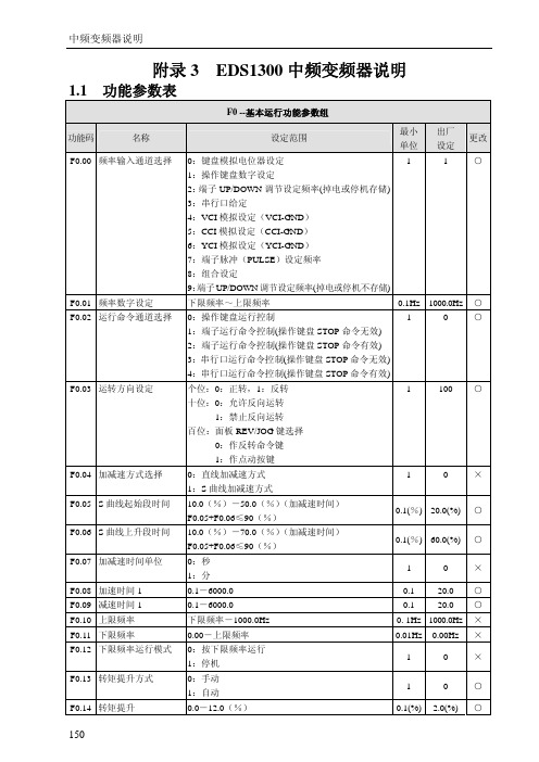
F2.42 VF 电压值 2
F2.40-F2.44
0.01% 50.00% ○
F2.43 VF 频率值 3
F2.41-上限频率
0.01Hz 40.00Hz ○
F2.44 VF 电压值 3
F2.42-100.0%(额定电压)
0.01% 80.00% ○
F2.45 跳跃频率 1
0.0-1000.0Hz
0.1Hz 0.00Hz ×
10.0(%)-70.0(%)(加减速时间) F0.05+F0.06≤90(%)
0.1(%) 60.0(%) ○
0:秒 1:分
1
0
×
0.1-6000.0
0.1 20.0 ○
0.1-6000.0
0.1 20.0 ○
下限频率-1000.0Hz
0. 1Hz 1000.0Hz ×
0.00-上限频率
0.01Hz 0.00Hz ×
0:按下限频率运行 1:停机
1
0
×
0:手动 1:自动
1
0
○
0.0-12.0(%)
0.1(%) 2.0(%) ○
150
F0.15 V/F 曲线设定 F0.16 G/P 机型设置
中频变频器说明
0:恒转矩曲线
1
1:递减转矩曲线 1(2.0 次幂)
2:递减转矩曲线 2(1.7 次幂)
3:递减转矩曲线 3(1.2 次幂)
F3.28 LED 初始监控参数选择
1:CCI 模拟输入 2:VCI+CCI 3:VCI-CCI 4:Min{VCI,CCI} 5:Max{VCI,CCI} 6:脉冲反馈 0.00-10.00V 0.0-最大给定量; 相对于 10.00V 的百分比 0.0(%)-100.0(%) 最小给定量-100.0(%) 0.0%-100.0(%) 0.000-9.999 0.000-9.999 0.000-9.999 0.01-1.00s 0.0-20.0(%)相对于 10.00V 的百分比 0.0-100.0(%) 0-上限频率 0.0-6000s
天津商科中频控制器培训

显示控制器规范号
与控制器通讯连接口
编程:在此方式下可对某 一规范中的焊接参数进行 修改、编程。 测试:可用于试验焊接加 压情况,不输出焊接电流。 焊接:正式焊接时应选此 方式。 监视:对控制器的特殊参 数进行监视。 复制:实现控制器与编程 器之间的数据操作。
规范选择键:用+、-键可 选择需要的规范
编程器复制功能的使用说明
• 3)编辑数据 • 对选定组码内的32套焊接规范数据进行编辑修改。操作方
法同编程状态一致,所不同的是编程状态修改的是控制器内 的数据,而编辑数据修改的只是编程器内存储的数据。 • 按“方式”键可随时终止编辑数据操作,返回到“复制”选 择状态。 • 4)校验数据 • 对选定组码内的32套焊接规范数据同控制器内的32套焊接 规范数据进行比较。编程器提示“校验数据中”,表示正在 校对数据。若相同,编程器提示“数据一致”,若不同,则提 示“数据不一致”。按“确认”键,返回到“复制”选择状 态。
附图1
附图2 外箱主电路接线图
附图3 箱体线排接线图
附图4 灯板接线图
逆变点焊机与工频点焊机比较
• 1、焊接质量 • 工频交流焊机的调节周期较长,对50Hz的
电网,焊接时间调节分辨率为20ms。逆变 直流点焊机时间调节分辨率可达1ms(1kHz 逆变频率),控制精度高。逆变焊机的反馈 控制的响应速度明显加快,输出稳定性好
2.夹紧功能控制
夹紧开关(X11-4)闭合后,修磨阀(X13-6)输出有效,起动开关 起动一次,加压阀输出有效,再起动一次加压阀输出断开。夹 紧时,加压阀输出有效。夹紧时不能焊接。(见附图1)
中频控制器故障及对策
1.气阀电源电压低:检查气阀工作电源(X12接线端子24V2)是否正常; 2.逆变驱动故障:逆变过程中IGBT器件过电流或相应的驱动电路工作 不正常;逆变驱动故障会使空开脱扣; 3.散热板过热:首先检查流过散热器的水温度是否过高, 其次,检查散热板上的温度继电器是否损坏,常态下开关是闭合的; 4.原边电流异常:<1>逆变器输出电流过大,<2>中频变压器对地短路 ,<3>主控板检测异常;原边电流异常会使空开脱扣。 5.电容器电压异常:表明电容器上的电压超出正常范围,检查电容器 充电是否正常;检查供电电网工作是否稳定; 6.变压器温度过高:检查变压器的水温是否过高;检查变压器内温度 继电器是否损坏; 7.主24v电源低:检查主板上工作电源24v(X2端子24V1)是否正常; 8.编程参数异常:检查起动的焊接规范中的参数是否有超范围的; 9.起动禁止:当前规范已经设置为禁止起动模式; 10.整流二极管异常:变压器整流二极管出现异常,短路或断开。
AIMS Power 10,000瓦直流到交流电源逆变器 (V 2.0) 使用说明书
DC TO AC POWER INVERTER PWRINV10KW12VInstruction ManualIntroductionThe AIMS Power 10,000 watt inverter is the most technology advanced mobile DC to AC power inverter available. AIMS also offers the 8,000 Watt 12V or 12,000 Watt 24V.This inverter is used in a wide range of applications including back up power for remotehomes, off-grid systems, RVs, boats, commercial vehicles and mobile businesses. The10,000 watt inverter will operate most pumps, motors, lights, heaters, compressorbased appliances and hand tools.To get the most out of the power inverter, it must be installed and used properly. Readthe instructions in this manual before installing and using this product. Follow all safetyprecautions.FUNCTIONSFRONT VIEWA. On/Off switch: Leave in the OFF position during installation.B. Over temperature indicator: Lights when inverter protects itself against overheating. Invertershuts down while indicator is on. Inverter will restart automatically and indicator will turn off when the inverter cools.C. Over load indicator: Lights when inverter shuts down because of overload. Indicator will turn offand inverter will restart when overload is removed.D. Bar meters: Displays battery voltage and current. Current should be in the green zone forcontinuous operation. The inverter will operate for several minutes when the current is in the yellow zone. Operation with battery voltage or current in the red zone of a meter will result in protective shutdown of inverter.E. AC outlets: Maximum recommended output per outlet is 1500W.F. Remote port: Used with remote switch to turn inverter ON/OFF (sold separately).G. AC terminal block: Hard wire block providing inverter's full power.E: AC outletsD: Bar metersB: Over temperature indicatorA: On/Off switch C: Over load indicatorG: AC terminal Block F: Remote portREAR VIEWA: Fan: Do not obstruct, allow at least 12 inches for air flow.B: Battery terminals: Connect to 12V, or 24V, or 36V, or 48V (depending on inverter model) battery(s) or other DC power source. "+" is positive & " - " is negative. Reverse polarity connection will blow internal fuse and may damage inverter permanently. Make sure you check your input voltage and do not REVERSE POLARITY! This will void the warranty.C: Chassis ground lug: Connect to earth ground or to vehicle chassis using #8 AWG wire. Warning! Operation of the inverter without a proper ground connection may result in an electrical safety hazard.QUICK HOOK-UP AND TESTINGIf you would like to quickly hook-up the power inverter and check its performance before moving forward with your installation, please follow these guidelines:1. Unpack and inspect the power inverter, check to see that the power switch is in the OFF position.2. Before you connect the battery cables, make sure the power switch is in the off position. Connect Red (+) battery cable to Red (+) inverter terminal. Connect Black (-) battery cable to Black (-) inverter terminal. Connect Red (+) battery cable to Red (+) battery terminal. Connect Black (-) battery cable to Black (-) battery terminal. Alligator clamp cables may be used but only to connect to the battery. Do not use clamps on inverter terminals. Alligator clamps are not a permanent solution. You may see a spark during connection. Do not reverse the polarity. This may damage the inverter and void warranty. Caution! Loosely tightened connectors result in excessive voltage drop and may cause overheated wires and melted insulation. Reverse polarity connection will blow a fuse in inverter and may permanently damage the inverter. Damage caused by reverse polarity connection is not covered by our warranty. Warning! You may observe a spark when you make this connection since current may flow to charge capacitors in the power inverter. Do not make this connection in the presence of flammable fumes, as explosion or fire may result.A: FanB: Battery terminal (+)B: Battery terminal (-)C: Chassis grounding3. Set the power switch to the on position. Check the meters and indicators on the front panelof the inverter. The voltage bar graph should indicate 11 to 14 volts depending on the voltageof the power source. If it does not, check your power source and the connections to inverter.The other indicators should be off.4. Set power inverter switch to the OFF position, the indicator l ights may blink and theinternal alarm may sound momentarily. This is normal. Plug the test load into the ACreceptacle on the front panel of the inverter. Leave the test load switch off.5. Set power inverter switch to the ON position and turn the test load on, the inverter shouldsupply power to the load. If you plan to measure the true output R.M.S. voltage of inverter, ameter such as FLUKE 87A, BACKMAN 4410 or TRIPLETT 4200 must be used.INSTALLATION1. Where to installThe power inverter should be installed in a location that meets the following requirements:a. Dry - Do not allow water to drip or splash onto the inverter.b. Cool - Ambient air temperature should be between 0°C and 40°C, the cooler the better when operating in this rangec. Ventilation - Allow at least one inch of clearance around the inverter for air flow. Ensure the ventilation openings on the rear and bottom of the unit are not obstructed.d. Safety - Do not install the inverter in the same compartment as batteries or in any compartment capable of storing flammable liquids such as gasoline.2. CablesDC to AC inverters require high amperage/low voltage DC power to low amperage/high voltage AC power. To operate properly, connect inverter DC input terminals direct to battery with heaviest wire available see below:12 Volt Model: 2x set of 4/0 AWG (2 red + 2 black) and quantity 2- ANL500KIT-500 Amp fuse kits for positive (red) cablesBattery Cables InstallationWhen connecting the AC inverter to the battery terminals, it is important to connect the "+" wire to the "+" terminal and the wire to the "-" wire to the “-“ terminal. Do NOT reverse the polarity. It will void the warranty. Make sure you connect negative to negative and positive to positive.Red (+) * 2Black (-) * 2REDBLACKCaution!DO NOT allow the wires to cross or touch each other. Install the cables facing away from each other and screw tightly. When connecting the battery cables to the terminals of the inverter, make sure they do not touch the case.3. GroundingThe power inverter has a lug on the rear panel marked "chassis ground" This is to connect the chassis of the power inverter to the ground.The ground terminals in the AC outlets on the front panel of the inverter are also connected to the ground lug.The chassis ground lug must be connected to a grounding point, which will vary depending on where the power inverter is installed. In a vehicle, connect the chassis ground to the chassis of the vehicle. In a boat, connect to the boat's grounding systems in a fixed location, connect the chassis ground lug to an earth point, which will vary depending on where the power inverter is installed.The neutral (common)conductor of the power inverter AC output circuit is connected to the chassis ground. Therefore, when the chassis is connected to ground, the neutral conductor will also be grounded.This conforms to national electrical code requirements that separately derived AC sources (such as inverters and generators) have their neutral tied to ground in the same way that the neutral conductor from the utility line is tied to ground at the AC breaker panel.Caution! The Negative DC input of the power inverter is connected to the chassis. DO not install the power inverter in a positive ground DC system. A positive ground DC system has the positive terminal of the battery connected to the chassis of the vehicle or to the grounding point.Warning! Do not operate the power inverter without connecting it to ground. Electrical shock hazard may result.OPERATIONTo operate the power inverter, turn it on using the ON/OFF switch on the front panel. The power inverter is now ready to deliver AC power to your loads. If you are operating several loads from the power inverter, turn on separately after the inverter has been turned on. This will ensure that the power inverter does not deliver starting currents to all of the loads at once.1. Controls and indicatorsThe ON/OFF switch turns the control circuit in the power inverter on and off. It does not disconnect power from the power inverter.When the switch is in the OFF position, the power inverter draws no current from battery. When the switch is in the ON position but with no load, the power inverter draws less than 450 mA.2. Battery voltage indicatorThe battery voltage bar graph indicates the voltage at the input terminals of the power inverter. At low input current, this voltage is very close to the battery voltage. At high input current, this voltage will be lower than the battery voltage because of the voltage drop across the cable and connections.Ideally, the voltage should remain in the green area of the bar graph. If the voltage goes into the red area at top or bottom of the graph, inverter may shut-down.3. Battery current indicatorThe battery current bar graph indicates the current drawn from the battery by the power inverter, it will not indicate current by other loads also connected to the battery. The indicator only displays DC volts and amps.For long term operation, the current should be in the green area of the bar graph. Short term operation is possible with current in the orange area. If the current rises to the red area, the inverter will reduce its output voltage to protect itself.To measure AC current, use a TRUE RMS MULTI METER.4. Over temp indicatorThe over temp indicator indicates that the power inverter has shut itself down because it has become overheated. The power inverter may overheat because it has been operated at power levels above its rating, or because it has been installed in a location which does not allow it to dissipate heat properly.5. Over load indicatorThe over load indicator indicates that the power inverter has shut itself down because its output circuit has been short circuited or drastically overloaded. Switch the ON/OFF to OFF, correct the fault condition, and then switch the ON/OFF back to ON.THINGS TO CONSIDER REGARDING THE LOADThe 10,000W inverter will operate most AC loads within its power rating. When determining whether a microwave oven can be operated by the 10,000W inverter, remember that the power commonly advertised for microwave ovens is the cooking power (the power delivered to the food) not the power actually consumed by the microwave oven. The microwave oven will consume 40% to 100% more than its advertised cooking power. Check the rating sticker on the back of the oven to determine its actual power draw. The 10,000W inverter will operate small microwave ovens (0.2 to 0.3 cubic foot capacity) that draw is about 1700 watts.Some induction motors used in refrigerators, freezers, pumps, and other motor operated equipment require very high surge currents to start. The power inverter may not be able to start some of these appliances even though their rated current draw is within the rating of the power inverter.If a motor refuses to start, observe the battery voltage indicator while trying to start the motor. If the battery voltage indicator drops below 10.5V DC while inverter is attempting to start the motor, this may be why the motor won't start.Make sure that the battery connections are good and that the battery is fully charged. If the connections are good and the battery to is charged, but the voltage still drops below 11 volts, you may need a larger battery or larger battery bank.(*2 for 24V *3 for 36V *4 for 48V)INPUT VOLTAGEThe power inverter will operate from input voltage ranging from 10V-16V. If the voltage drops below input range, an audible low battery warning will sound and the voltage indicator will be in the lower red zone. The power inverter will shut down if the input voltage drops below 10V +/- .5V. This protects your battery from being over discharged.The power inverter will also shut down if the input voltage exceeds 17V +\-.5V. This protects the inverter against excessive input voltage.The voltage indicator will be in the upper red zone. Although the power inverter incorporates protection against over voltage, the inverter is at risk of permanent damage if the input voltage is allowed to exceed 17V +\-.5V.TROUBLESHOOTINGmon problemsa. Buzz in audio systems:Some inexpensive stereo systems and radios will emit a buzzing noise from their loudspeakers when operated from the power inverter. This is because the power supply in the device does not adequately filter the modified sine wave produced by the power inverter. The only solution is to use a sound system that incorporates a higher quality power supply.b. Television interference:Operation of the power inverter can interfere with television reception on some channels. If this situation occurs, the following steps may help to alleviate the problem.-Make sure that the chassis ground lug on the back of the power inverter is solidly connected to the ground system of your vehicle, boat or home.-Do not operate high power loads with the power inverter while watching television.-Move the television as far away from the power inverter as possible.-Keep the cables between the battery and the power inverter as short as possible and twist them together with about 2 to 3 twists per foot. This minimizes radiated interference from the cables.SPECIFICATIONSAIMS Corp., Inc. dba AIMS Power Warranty Instructions:This product is designed using the most modern digital technology and under very strict quality control and testing guidelines. If, however you feel this product is not performing as it should, please contact us:**************************(775)359-6703We will do our best to resolve your concerns. If the product needs repair or replacement, make sure to keep your receipt/invoice, as that will need to be sent back along with the package and RMA# prepaid to AIMS. You have a full 1 year warranty from date of purchase.This warranty is valid worldwide with the exception that freight and duty charges incurred outside the contiguous 48 United States will be prepaid by customer.Except as provided above, AIMS Power makes no warranty of any kind, express or implied, including without limitation the implied warranties of merchantability and fitness for a particular purpose. In no event shall AIMS be liable for indirect, special or consequential damages. This warranty only applies to AIMS Power branded products. All other name brand products are warranted by and according to their respective manufacturer. Please do not attempt to return non-AIMS Power branded products to AIMS Power.For additional products such as:-Modified sine wave inverters-Pure sine wave inverters-Low Frequency Inverters-Solar Charge Controllers-Micro Grid Tied Inverters-Inverter Chargers and Automatic transfer switches-Converters DC-DC-Custom cut cables-Batteries-Solar Panels & RacksPlease visit our web site: Tofindoutwheretobuyanyofourproducts,youmayalsoe-mail:************************ (775)359-6703.。
中频电源说明书

中频电源说明书
DZP系列中频静变电源是新一代航空地面电源,专为民航科技和军用飞机等在生产检测、维修和维护时提供400HZ的外部供电。
产品采用十二脉冲整流,高性能FPGA作为中央处理器,纯数字测量控制技术,LCD屏显示,造型新颖美观、结构设计合理,具有高稳定性和高可靠性,低失真正弦波输出,动态响应快,飞机供电连锁等功能,而且完全满足室外IP55防护等级,超宽(-40~55℃)的工作温度范围,良好的电磁兼容容性等等,是一台安全、可靠、高效、纯净的高端航空地面电源。
参照以下规范:
《GJB1910-94 飞机地面电源通车规范》
《GJB181-86 飞机供电特性及对用电设备的要求》
《GJB572-88 飞机地面电源供电特性及一般要求》
《MH/T6018-1999 地面静态电源》。
标准交流电动机用户指南说明书
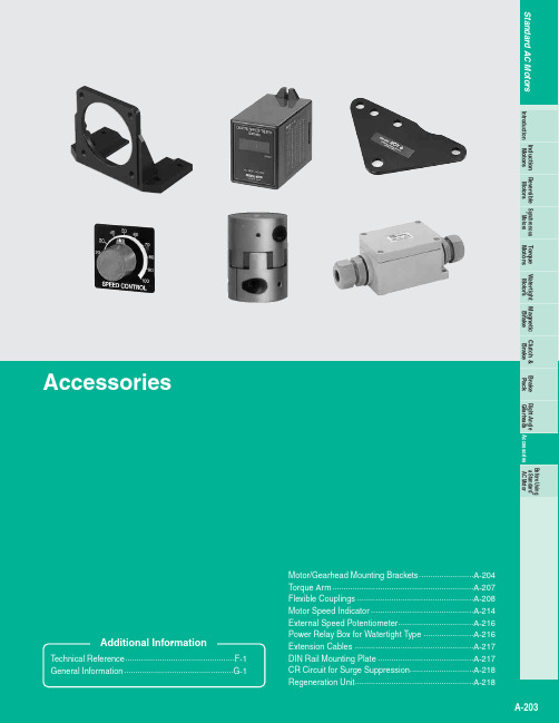
A-204ⅥFor Motor Frame Size: Ⅺ1.65 in. (Ⅺ42 mm)ⅷModel: SOL0U04Weight: 2.8 oz. (80 g) Material: Aluminum d A320U◆Compatible Motor and Gearhead0GN ⅪKAMotor Frame Size Ⅺ1.65 in. (Ⅺ42 mm) Round Shaft T ype MotorsAXH Series Round Shaft T ypeⅷDimensions Scale 1/4, Unit = inch (mm)ⅷModel: SOL0BWeight: 3.0 oz. (85 g) Material: Aluminum d B267◆Compatible Motor and GearheadAXH Series Geared T ypeⅷDimensions Scale 1/4, Unit = inch (mm)ⅥFor Motor Frame Size: Ⅺ2.36 in. (Ⅺ60 mm)ⅷModel: SOL2U08, SOL2M4Weight: 4.2 oz. (120 g) Material: Aluminum d A321U (SOL2U08)d A321 (SOL2M4)◆Compatible Motor and Gearhead●SOL2U082GN ⅪKAMotor Frame Size Ⅺ2.36 in. (Ⅺ60 mm) Round Shaft T ype Motors●SOL2M4V Series BX Series FBL 2SeriesAXU Series Round Shaft T ype AXH SeriesⅷDimensions Scale 1/4, Unit = inch (mm)Motor/Gearhead Mounting BracketsEleven kinds of mounting brackets for motors and gearheads are available. These brackets come with tapped holes. T o mount the motor and gearhead, simply fasten with the screws provided to the gearhead. T o mount the motor alone, mounting screws must be provided separately. Please note that these mounting brackets cannot be used with the following products.●Right-angle Gearheads ●5GC ⅪKA and 5GCH ⅪKA ●Watertight MotorsA-205Induction Motors Synchronous MotorsTorque MotorsWatertight Motors Magnetic BrakeClutch &BrakeBrake Pack Reversible Motors Right-Angle Gearheads AccessoriesIntroductionBefore Using a Standard AC MotorWeight: 5.6 oz. (160 g) Material: Aluminum d A322U (SOL3U10)d A323 (SOL3M6)◆Compatible Motor and Gearhead●SOL3U103GN ⅪKAMotor Frame Size Ⅺ2.76 in. (Ⅺ70 mm) Round Shaft T ype Motors●SOL3M6V SeriesⅥFor Motor Frame Size: Ⅺ3.15 in. (Ⅺ80 mm)ⅷModel: SOL4U10, SOL4M6Weight: 7.1 oz. (200 g) Material: Aluminumd A236U (SOL4U10)d A237 (SOL4M6)◆Compatible Motor and Gearhead●SOL4U104GN ⅪKAMotor Frame Size Ⅺ3.15 in. (Ⅺ80 mm) Round Shaft T ype Motors●SOL4M6V Series BX Series FBL 2SeriesAXU Series Round Shaft T ype AXH SeriesⅷDimensions Scale 1/4, Unit = inch (mm)A-206Weight: 9.5 oz. (270 g) Material: Aluminum d A238U (SOL5UA )d A239 (SOL5M8)◆Compatible Motor and Gearhead●SOL5UA 5GN ⅪKA 5GU ⅪKAMotor Frame Size Ⅺ3.54 in. (Ⅺ90 mm) Round Shaft T ype Motors●SOL5M85GU ⅪKHA V Series BX Series FBL 2SeriesAXU Series Round Shaft T ype AXH SeriesⅥFor Motor Frame Size: Ⅺ4.09 in. (Ⅺ104 mm)ⅷModel: SOL6M8Weight: 13.4 oz. (380 g) Material: Aluminum d A240◆Compatible Motor and GearheadBH Series (Except for Right-Angle Shaft)BHF Series (Except for Right-Angle Shaft)BX SeriesⅷDimensions Scale 1/4, Unit = inch (mm)A-207AC MotorsInduction Motors Synchronous MotorsTorque Motors Watertight Motors Magnetic BrakeClutch &Brake Brake Pack Reversible Motors Right-Angle Gearheads AccessoriesIntroduction Before Using a Standard AC MotorTorque ArmThe torque arm serves as an anti-rotation guide for the gearhead when a right-angle hollow-shaft type gearhead is used in a shaft-mounted fashion (with the gearhead mounted on the shaft of a connected device). When using it as a shaft-mounted gearhead, be sure to use a torque arm and secure the gearhead to the device.ⅷDimensions Scale 1/4, Unit = inch (mm)Weight: 5.1 oz. (145 g)ⅷPanel Cutout Scale 1/4, Unit = inch (mm)For BH Series, BHF Series Right-Angle Gearhead/Hollow ShaftⅷMounting MethodWhen mounting on a device, secure the torque arm firmly using an M10 or 3/8-16 UNC screw.✽✽ⅷModel: SOT6◆Applicable ProductsBH Series Right-Angle Gearhead/Hollow Shaft BHF Series Right-Angle Gearhead/Hollow Shaft 5GU ⅪRH GearheadA-208Flexible CouplingsⅥFeatures●Couplings come with shaft holes and have standardized combinations for different diameter shaft holes.●Characteristics are the same for clockwise and counterclockwise rotation.●Oil-resistant and electrically insulated.●Aluminum alloy construction.●The shaft being driven is not damaged, since shafts are joined by clamping.●Easy installation due to a separated hub and sleeve design.ⅥMounting on a shaftThe MCL Couplings are a clamp type for mounting the flexible coupling to the shaft.Clamp TypeClamp type couplings use the binding force of the screw to compress the axis hole diameter and thereby fasten the coupling to the shaft. This does not damage the shaft and is easy to mount and remove. The following table shows thescrew tightening torque.ⅥAlignment AdjustmentFlexible couplings tolerate misalignment of the axis center and transfer rotational angle and torque, but produce vibration when the permissible value for misalignment is exceeded. This can dramatically shorten the coupling's service life. Misalignment of the axis center includes eccentricity (parallel error of both centers), declination(angular error of both centers) and end play (shaft movement in the axial direction). T o keep misalignment to within the permissible value, always check and adjust the alignment. T o increase the service life of the coupling, we recommend keeping misalignment to below 1/3 of the permissible value.Notes :●Misalignment or excessive torque beyond the permissible values will deform the coupling and shorten its service life.●If you hear a strange metallic noise from the coupling while it is running, stop the motor immediately and check for misalignment, shaft interference, loose screws, or the like.●When load fluctuates substantially, paint adhesive over the screws or switch to a larger coupling diameter. This helps prevent coupling screws from coming loose.●When using couplings that have no key grooves, as on the MCL20,MCL30,MCL40and MCL55fasten clamping screws before fastening set screws.●Only use the screws specified by Oriental Motor. Other screws may damage the couplings.●Do not bring fingers or hands into contact with an operating coupling as injury may result. Always use protective covers to prevent accidents. Also, install safety systems that stop motor rotation as soon as the protective cover is opened.●Always be sure the power is off during installation. Should the drive unit accidentally start running, injury can occur by being drawn into the device.Always check that the devices main power supply is off before performinginstallation work.●For Applicable Products ➝A-209ⅥProduct Number CodeⅥSelecting a Flexible CouplingOnce you have decided on a motor and the shaft diameter of the equipment to be connected to it, select the proper flexible coupling to use. Oriental Motor's flexible couplings areavailable in external diameter sizes that provide the strength required for the motor torque.●For uniform load, when the motor is a 4GN ⅪKA (shaft outer diameter of 0.375 inch) and the shaft diameter of the equipment to be connected to the motor is 0.375 inch, use an MCL30F06F06.●For shock-applied use, when the gearhead is a 4GN ⅪKA (shaft outer diameter: 0.375 inch) and the shaft diameter of the equipment to be connected to the motor is 0.375inch, use anMCL40F06F06MCL 30 F06F06ExampleInner Diameter d1Inner Diameter d2MCL 40 F08 F10Flexible CouplingOuter Diameter of Coupling20: 0.79 (20 mm)ϳ65: 2.56 (65 mm)Inner Diameter d1 (Small Inner Diameter)06: 0.2362 in. (6 mm)ϳ25: 0.9843 in. (25 mm)F03: 3/16 in. (4.762 mm)ϳF12: 3/4 in. (19.05 mm)Inner Diameter d2 (Large Inner Diameter)06: 0.2362 in. (6 mm)ϳ25: 0.9843 in. (25 mm)F03: 3/16 in. (4.762 mm)ϳF12: 3/4 in. (19.05 mm)Fasten the screws so that they make a right angle with the surface of shaft flat.A-209MotorsInduction Motors Synchronous MotorsTorqueMotorsWatertight Motors MagneticBrakeClutch &BrakeBrake PackReversible Motors Right-AngleGearheads AccessoriesIntroductionBefore Usinga Standard AC MotorⅥApplicable ProductsCouplings are also available for round shaft motors if a shaft diameter matches.●Enter A , C or S ●Enter U or E in the under bar (_) within the model name.●Enter the gear ratio in the box (Ⅺ) within the model name.●Types of the load in this table are of common use. Check the applicable values of each coupling for exact values.●The specifications above are the values when combined with Oriental Motor's motor and gearhead. A-210A-211AC MotorsInduction Motors Synchronous MotorsTorque MotorsWatertight Motors MagneticBrakeClutch &BrakeBrake PackReversible Motors Right-Angle Gearheads AccessoriesIntroductionBefore Using a Standard AC MotorⅥDimensions Scale 1/4, Unit = inch (mm)ⅷMCL20TypeⅷMCL30ⅷMCL3010F05ⅷMCL3010F06ⅷMCL3010F08ⅷMCL3012F05ⅷMCL3012F06ⅷⅷⅷⅷⅷA-212ⅷMCL4010F05ⅷMCL4010F06ⅷMCL4010F08ⅷMCL4012F06ⅷMCL4012F08ⅷMCL40F08F10ⅷMCL4014F06ⅷMCL4014F08ⅷMCL4015F06ⅷMCL4015F08ⅷMCL4012F10ⅷMCL4014F10ⅷMCL4015F10ⅷMCL40F10F10A-213AC MotorsInduction Motors SynchronousMotorsTorque MotorsWatertight Motors Magnetic BrakeClutch &BrakeBrake PackReversible Motors Right-Angle Gearheads AccessoriesIntroductionBefore Usinga Standard AC MotorⅷMCL55TypeⅷMCL5515F08A-214ⅷMCL65TypeMotor Speed IndicatorT o display or check the speed at the output shaft of the motoror gearhead, connect the speed indicator.ⅥDigital Display TypeⅷModel: SDM496(Single-Phase 100 V ϳ240 V)ⅷIncluded with SDM496To mount in a panel, a flush mounting adapter EPUA-31and round shape socket EP11MS are provided with the speed indicator.This product is a digital speed indicator that directly displays the speed at the output shaft of the motor or gearhead.SDM496is not approved by any safety standards.v Applicable ProductsFBL 2Series, AXU SeriesAXH Series, US Series, ES01/ES02BHF SeriesA-215MotorsInduction Motors Synchronous MotorsTorque MotorsWatertight Motors Magnetic BrakeClutch &BrakeBrake PackReversible Motors Right-Angle Gearheads AccessoriesIntroduction Before Using a Standard AC MotorⅷDimensionsScale 1/4, Unit = inch (mm)Weight: 7.1 oz. (200 g)d A100ⅷDimensions with Adapter AttachedScale 1/4, Unit = inch (mm)ⅷFlush Connecting Socket for Mounting DIN Rail(Model: EP11PF ) (Sold separately)Weight: 2.8 oz. (75 g)ⅷPanel Cut-OutⅷExample of Connectionv AXU Series, AXH Series (30 pulses/rotation)✽For AXUSeries, replace "GND" with "COM".SDM496Power Supply InputSingle-Phase 100 VAC ϳ240 VAC 50/60 Hz✽Driverv USSeriesPower Supply InputSingle-Phase 100 VAC ϳ50/60 HzSDM496Speed Control Packv BHFSeriesSDM496Power Supply InputSingle-Phase 100 VAC ϳ240 VAC 50/60 HzInverterv FBL 2Series (12 pulses/rotation)SDM496Power Supply InputSingle-Phase 100 VAC ϳ240 VAC 50/60 HzDriverv ES01/ES02Power Supply InputSingle-Phase 100 VAC ϳ50/60 HzSDM496ES01/ES02A-216ⅷModel: PAVR-20KZ(20 k Ω, 1/4 W, with a linear resistance vs. angle curve)v Applicable ProductsBX Series FBL 2Series AXH Series BHF Series ES01/ES02ⅷDimensions Scale 1/2, Unit = inch (mm)Weight: 0.71 oz. (20 g)✽A dial plate provided with the speed potentiometer.✽Recommended thickness of a mounting plate is a maximum 0.177 inch (4.5mm).Note :●One set of this external speed potentiometer is provided with speed control packs and drivers shown for the applicable products on the left (Except for AXH Series and BHF Series).t=0.02 (0.5)t=0.02 (0.5)External Speed PotentiometerⅷModel: TB4-0608(4-Terminal Type)v Applicable MotorsFPW Series BH SeriesApplicable cable diameter:0.26 in. (6.5 mm)ϳ0.33 in. (8.5 mm)Power Relay Box for Watertight TypeⅷDimensionsScale 1/4, Unit = inch (mm)Weight: 5.3 oz. (150 g)●The relay box conforms to the protection level IP65 only when used with a splash proof extension cable for an FPW series motor. (Does not conform to the protection level IP65 when used with a BH Series motor.)The screws for the cover on the sealed connector and relay box should be adjusted to the torque shown below.Sealed connector 8.8ϳ13.2 lb-in. (1.0ϳ1.5 N •m)Cover of power relay box 4.7ϳ5.8 lb-in. (0.54ϳ0.66 N •m)✽This product can be used with lead wire type motors. However, they are not waterproof. Also, note that lead wires cannot be fixed with the sealed connectors.A-217Induction Motors SynchronousMotorsTorque MotorsWatertight Motors Magnetic Brake Clutch &BrakeBrake PackReversible Motors Right-Angle Gearheads AccessoriesIntroduction Before Using a Standard AC MotorUse with the power relay box for watertight. An extension of 16.4 ft. (5 m) and 32.8 ft. (10 m) is possible.Extension CablesⅷSpecificationsConductor construction: Refer to the dimension on the rightFinished outer diameter: 3 conductors, 4 conductors: 0.31 in. (7.8 mm)Outer casing: Heat-resistant vinyl chloride3 Conductors: UL Style 3271, AWG 20ϫ34 Conductors: UL Style 1015, AWG 20ϫ3UL Style 1430, AWG 20ϫ1DIN Rail Mounting PlateⅥFor Drivers and Speed Control PacksThis mounting plate is convenient for installing the speed control packs and drivers on DIN rails with ease.ⅷModel: PADP01v Applicable MotorsBX Series FBL 2Series BHF SeriesⅷDimensionsScale 1/4, Unit = inch (mm)Weight: 0.71 oz. (20 g)Unit = inch (mm)A-218Regeneration UnitThis absorbs energy that is regenerated during avertical (gravitational) operation or an abrupt start/stop.ⅷModel:EPRC-400PⅷDimensionsScale 1/4, Unit = inch (mm)Weight: 8.8 oz. (250 g)dC194➁➂ ➃–➁–➂ : AWG 18x2For regeneration current Connect to RG Terminal : AWG 22x2For thermal signal (For BHF Series, connect to I-COM and TP terminal)ⅷModel: EPCR1201-2250 VAC (120 Ω, 0.1 F)ⅷDimensionsScale 1/2, Unit = inch (mm)Weight: 0.18 oz. (5 g)This product is used to protect the contacts of the relay and/or switch used in the forward/reverse circuit section or the instantaneous stop circuit section of a motor.CR Circuit for Surge SuppressionⅷSpecificationsv Applicable MotorsBHF Series。
- 1、下载文档前请自行甄别文档内容的完整性,平台不提供额外的编辑、内容补充、找答案等附加服务。
- 2、"仅部分预览"的文档,不可在线预览部分如存在完整性等问题,可反馈申请退款(可完整预览的文档不适用该条件!)。
- 3、如文档侵犯您的权益,请联系客服反馈,我们会尽快为您处理(人工客服工作时间:9:00-18:30)。
中频交流阻焊控制器SVF2使用说明书天津商科数控设备有限公司地址:天津经济技术开发区逸仙科学工业园庆龄大路17号电话:022-********传真:022-********网址:邮箱:tjsunke@目录一.引言 (2)二.中频交流电阻焊接系统组成 (3)三.工作方式 (5)四.编程器使用及编程软件操作 (7)五.功能设置 (10)六.焊枪配置 (12)七.电流递增功能、电极修磨 (13)八.电流监控 (14)九.压力控制功能 (15)十.涂层处理功能 (16)十一.中频交流控制器故障及对策 (16)十二.注意事项 (17)附表1中频交流控制器编程参数表 (18)附表2递增器计数及复位 (24)附表3监视参数表 (25)附表4规范选择 (26)附图1主板输入输出端子接线图 (27)附图2中频交流控制器与变压器接线图 (28)一.引言1.1中频交流阻焊控制器工作原理1.2中频交流控制器电流波形与工频控制器电流波形对比普通工频交流50HZ ,次级电流10.0KA ,变压器圈比80中频交流50HZ ,次级电流10.0KA ,变压器圈比80三相交流50/60Hz 电源输入,经整流、滤波变成平滑的直流电,以IGBT/K1作开关器件产生交替的电压输出,通过调整高频(5KHz)工作的IGBT/K2的开通脉冲宽度实现设定的焊接电流输出。
1.3相对于普通的工频控制器,中频交流控制器有着如下的优点:1.三相交流电源输入,用电平衡;功率因数高;2.对相同的焊接工件,焊接时间缩短,省电;焊接稳定区加大;电极寿命增长;3.铝、镀锌板、高张力钢、不锈钢、镁合金、碳钢、钛各种材质均可焊接,焊接结果良好;4.尤其适合于三层板焊接、非常薄的材料的焊接以及精密焊接的要求;5.少飞溅;6.对电流的快速响应控制提高了焊点的质量。
二.中频交流电阻焊接系统组成如图所示:整个焊接系统由控制器、焊接变压器、工件组成。
其中控制器又包含多个部分,有电源驱动、整流部分、电容板、IGBT、以及主控板部分。
主要特点:1.中频交流控制器输出电源频率:15.0Hz~400.0Hz可编程;2.可编程最多256套焊接规范;3.三段加热过程:预热、焊接、回火;其中焊接段中可以自己定义递增和递减段;4.可编程压力控制,最多可定义10个压力段;5.焊点计数功能。
技术参数1.输入电压:三相380V,50HZ/60HZ,电源波动+10%,-20%;2.输出电压:单相PWM输出500V;3.输出电流:依控制器型号,最大峰值电流为400A@暂载率10%;4.风冷,风扇温度55℃开启,45℃关闭;5.工作环境温度:0~50℃;6.气阀规格:DC24V。
三.工作方式控制器可以有两种工作方式:单点点焊和连续点焊。
1.单点点焊:起动信号闭合后即开始焊接过程,焊接结束后输出保持终了信号。
每套焊接规范中都有一个“禁止起动”参数,可以允许或禁止起动,此参数为ON时不允许使用该焊接规范;为OFF时可以使用该套焊接规范。
下图为单点点焊时的工作时序图:2.连续点焊:连续点焊过程中,如果起动开关一直保持有效,那么电磁阀输出在维持时间过后会断开,焊钳张开,然后输出保持终了信号。
休止时间过后电磁阀会再次闭合,重新开始下一个焊接过程。
下图为连续点焊时的工作时序图:3.冷却比率(0-99.99%):(半周期时间-通电时间)/半周期时间*100.0%。
半周期半周期半周期半周期冷却比率:0冷却比率:20%四.编程器使用及编程软件操作1.编程器使用2.编程软件安装及使用1)安装直接点击Sunke.exe 文件,可直接安装。
2)通讯配置a.通讯端口为串口b.通讯线(直通线)显示控制器规范号与控制器通讯连接口显示控制器工作方式工作方式键:选择控制器工作于2种工作方式中的一个。
(1)焊接:正式焊接时应选此方式。
(2)监视:对控制器的特殊参数进行监视。
数据修改键:用数据键选择数据中的某一位,用数据+、-键修改该位数值,最后当认为数据已修改正确后,应按确认写入键才能把数据写入控制器中;否则按其它任何键,则修改的数据无效,规范参数中仍为原数值。
参数选择键:用参数选择键可以上、下移动参数表。
规范选择键:用+、-键可选择需要的规范显示焊接工作参数++数据工作方式参数规范确认写入c.通讯设置打开Sunke软件→“通讯”菜单→通讯及系统设置COM口根据实际情况设置。
3.软件基本功能介绍1)基本参数设置2)焊接方式切换编程方式:可以对参数进行编程;测试方式:起动后,有动作无电流输出;焊接方式:起动后,有焊接电流输出;监视方式:可以监视部分参数;焊点标示设置每个规范可以设定一个标示,每个标示最多用10个字符。
设定:选定需设定的规范,在下方输入栏中输入所需标示,按设置按钮后即可实现焊点标示设置。
五.功能设置1.主板SW2D的S5,S6,S7,S8意义如下所示:ON OFF S5未定义未定义S6未定义未定义S7未定义未定义S8系统参数输入允许,仅限于设备制造厂家使用。
2.Modbus通讯设置(SL1-SL5,SL6插块配置)半双工:SL1,SL2,SL3置于ON;全双工:SL1,SL2,SL3置于OFF;终端:SL4,SL5置于ON;SL6始终置于ON。
3.系统设置用编程器更改系统参数时,规范应设置为设定电极号+1的规范上。
六.焊枪配置1.辅助行程在大行程时禁止起动;(无效)2.辅助行程由大行程到小行程时,响应起动信号在时间限制(0~3s可设)过后。
(无效)3.当辅助电磁阀为双电控时,辅助行程开关动作后,辅助阀输出信号持续1s。
(无效)4.急停断开时,禁止起动和辅助行程动作。
5.辅助行程设置1)进入系统设置页面;系统密码输入2007后,设置焊枪辅助行程才可生效。
2)进入工具页面a.可配置焊枪单双行程;b.可配置单/双/多枪(只支持单/多枪配置);c.可配置电磁阀单双电控;d.单电控可配置行程开关方式;切换式:起动Retract Sol A;位置时:起动Retract Sol B;e.双电控行程开关方式为切换式。
(不支持)f.起动-规范选择方式分离:起动开关与规范选择互相独立(0对规范1控制有效);合一:不同的起动代表不同的规范。
g.0对规范1控制0对规范1:0000/1111。
七.电流递增功能、电极修磨为了补偿电极磨损造成的焊接电流密度降低现象,控制器提供了电流递增功能。
用户可以根据实际情况设定最多16个步增段。
在电流递增功能中涉及到了以下几个参数:平台N步增率,平台N焊点数,步增通知点,继续停止。
1.平台N焊点数:每一平台焊接点数。
2.平台N步增率:每一平台相对于基值电流的增量;平台1的电流为基值电流,其它平台电流=(1+平台N步增率)*基值电流。
3.步增通知点:在步增过程接近结束时的前第N个点通知用户步增过程即将结束。
4.继续/停止:继续时,当步增结束后报警但不终止焊接;停止时,当步增结束后报警停止焊接。
5.电极预警点:在最后一次修磨过程即将结束的时候,在结束前的第N个点提出预先警告,即电极预警点,其取值范围为0-99。
6.修磨次数:用户可以根据实际情况设定电极的总修磨次数。
八.电流监控电流监控功能用于检查在焊接过程中实际的电流,并且将反馈的电流值与设定的参考值以及超、欠限值进行比较。
当测定的电流值超出允许误差的时候,控制器会产生报警或预警信号。
当测量值低于允许的误差范围,如果允许补焊,那么控制器会补焊一次焊点,同时启动一个计数器,并与连补焊点数比较,当补焊次数大于等于连补焊点数时,会产生报警或预警信号;反之,如果不允许补焊,那么控制器会直接产生报警或预警信号。
对于每一个焊接脉冲可以单独设定电流监控功能。
当测得的电流值超过电流设定的误差的时候,会产生报警或预警信号。
对于预热、焊接、回火三个焊接过程,分别设定了电流参考值、超限值、许可欠限值和报警欠限值。
如图所示:1.预热(焊接或回火)参考值:可以设定一个实际的电流参考值,电流超限、欠限值等参数都以这个参考值为标准。
2.I*超限值:对于电流I*(*=1,2或3,分别对应着预热、焊接和回火三个过程)来说,相对于电流的参考值有一个超限范围,当实际的电流超出这个限定范围的时候,控制器会产生报警,这时控制器有可能只产生报警不中断焊接过程,也有可能就此中断焊接过程,此功能可以通过主板上的拨码开关S6设置。
3.I*报警欠限值:测量的电流值相对于参考的电流值有一个低限误差,即报警欠限值,当电流测量值超出允许的报警范围时会产生报警,此时有可能中断焊接,也有可能不中断焊接,而重新启动下一次。
4.I*许可欠限值:相对于电流参考值可以设定一个许可欠限值,它也是一个百分比,在许可欠限和报警欠限之间,可以引入一个参数:连欠限点数,即可以允许连续n个点位于许可欠限和报警欠限之间,如果超出点数n后即报警,并结束焊接过程。
5.连欠限点数:当实际的电流值落在了电流报警欠限和电流许可欠限之间的范围内,那么允许再焊一次,如果下一次仍然落在这个范围内,且没有超出“连欠限点数”范围,那么还可以再焊一次,直到达到连欠限点数设定值,如果下一点仍欠限,则控制器产生报警。
九.压力控制功能压力曲线中可以最多设置10个压力段,每段对应着一个压力和一个时间。
用户可以根据实际的应用情况设置比例阀的输出。
压力曲线时间段为加压开始到维持结束之间的时间。
1.压力基值:设定控制器待机状态时的压力值,它是比例阀最大输出压力的百分比。
实际输出压力=压力基值*比例阀最大输出压力2.压段1压力:压段1的压力相对于最大压力的百分比,同理,每一个压力段都对应一个压力值。
它以比例阀的最大输出压力为基准。
3.压段1时间:压段1的压力持续的时间。
同理,每一个压力段都对应一个时间值。
4.十.涂层处理功能a.只有预热在PHA方式时,涂层处理功能起作用。
b.涂层处理,涂层加热I,阈值I下限,报警I上限,报警I下限当报警I下限<预热电流<=报警I上限时,电流正常-→可转入涂层加热段→当涂层加热电流>=阈值I下限时,→可转入正常焊接段。
当报警I下限>=预热电流时,报电流过小,焊接过程终止;当报警I下限<预热电流时,报电流过大,焊接过程终止;当在涂层加热段时,涂层加热电流<阈值I下限,则延长预热时间(由“延时周波”),当延长该时间后仍不到阈值I下限,则报电流过小。
十一.中频交流控制器故障及对策故障码故障形式故障名称故障说明00设备正常控制器工作正常010气阀电源电压低检查气阀工作电源(X12接线端子24V2)是否正常;020逆变驱动故障逆变过程中IGBT器件过电流或相应的驱动电路工作不正常030散热板过热首先检查流过散热器的水温度是否过高,其次,检查散热板上的温度继电器是否损坏,常态下开关是闭合的,X7为温度继电器输入。