12V2000G25 3B Verbrauch WL deutsch
通信电台功率放大器参数

VHF-UHF功率放大模块资料部分大功率功放模块和常用高频发射管的参数!高频功率放大模块 t"Io*型号频率功率型号频率功率 gE\M M57704EL 335-360M 13W M67741L 135-160M 30W Y]O7M57704L 400-420M 13W M67741H 150-175M 30W kM57704H 450-470M 13W M67742 68-88M 30W 14)M57706 145-175M 8W M67743L 68-81M 7W oM57710A 156-160M 30W M67743H 77-88M 7W XM57716 430-450M 17W M67748L 135-150M 7W AqvKh@M57719L 135-145M 14W M67748H 150-175M 7W ?31xM57719 145-175M 14W M67749L 400-430M 7W L-gM57721L 350-400M 7W M67749H 440-470M 7W BKS!M57726 144-148M 43W M67760LC 806-870M 20W iQaM57729EL 335-360M 30W M67775 1465-1477M 7.5W wPpM57729SL 360-380M 30W M67776H 896-941M 5W CS~oM57729UL 400-420M 30W 4(M57729L 400-420M 30W M67781L 135-160M 40W D/4PNM57729H 450-470M 30W M67781H 150-175M 40W {di6M57735 50-54M 19W M67783 1240-1300M 1.4W ZJM57737 144-148M 30W M67789 1465-1477M 3W "M57774 220-225M 30W M68702L 135-160M 60W 'vUPM57775 806-866M 0.4W M68702H 150-175M 60W #RC'#/M57782 824-851M 7W M68703LA 400-430M 50W rEG =aM57788M 430-450M 40W M68703HA 440-470M 50W I*M57796MA 144-148M 7W M68706 250-270M 30W w_NdM57796H 150-175M 7W M68710L 400-430M 2W 5p#dM57797MA 430-450M 7W M68711 889-915M 3.8W :e`/`M57797H 450-470M 7W M68721 118-137M 10W &M67702 150-175M 60W M68729 220-245M 30W )4M67709L 350-390M 13W M68732SL 330-380M 7W aQq'M67711 1240-1300M 16W M68743H 896-941M 3.8W ]vP7M67715 1240-1300M 1.2W M68745L 806-870M 3.8W z\\M67723H 276-284M 1.5W M68745H 896-941M 3.8W I[_M67730L 175-200M 30W MHW803-3 870-905M 3W 75M67732 1240-1300M 1W S-AV17 144-148M 60W IV%M68762SL 360-380M 30W M68732H 118-137M 10W Do2xD常用发射三级管资料oX©『中国业余无线电』 -- 『中国业余无线电』X型号功率增益电压频率工作状态封装 123脚:[E©『中国业余无线电』 -- 『中国业余无线电』l2N3375 10W 5dB 28V 400MHz FM/AM/SSB TO-60]P2N3553 2,5W 10dB 28V 175MHz FM/AM TO-39 C B E2S\PD2N3632 20W 7dB 28V 175MHz FM TO-60g2N3866 5W 10dB 28V 400MHz WINTransceiver TO-39 C B ES2N3924 4W 6dB 13,6V 175MHz WINTransceiver TO-39?|.B2N4427 2W 10dB 12V 175MHz WINTransceiver TO-39l8N42N5108 1W 5dB 24V 1200MHz WINTransceiver TO-39 ]$Q2N5109 3,5W 11dB 15V 200MHz WINTransceiver TO-39({;8[#2N5421 3W 9dB 13,5V 175MHz WINTransceiver TO-39p7iTn2N5913 2W 7dB 12,5V 175MHz WINTransceiver TO-39h~}ETQ2N5943 1W 8dB 15V 400MHz FM TO-39z.2SC730 0,8W 10dB 13,5V 175MHz FM TO-39 C B E|2SC1096 10W 60MHz FM TO-2205Aa^2SC1173 10W 100MHz FM/AM/SSB TO-220-SF?:S2SC1306 16W 30MHz FM/AM/SSB TO-220 B C EP6Di!Y2SC1307 16W 12dB 12V 30MHz FM/AM/SSB TO-220 B C E~|97WO2SC1590 5W 10dB 12,5V 136-174MHz FM TO-220 B E C L(2SC1591 14W 7,5dB 12,5V 136-174MHz FM TO-220 B E C%2SC1678 5W 30MHz WINTransceiver TO-220 B C EZuG_N32SC1728 8W 80MHz WINTransceiver TO-202 E B Ca2SC1729 14W 10dB 13,5V 175MHz FM T-31ED~FW2SC1909 10W 14,5dB 13,5V 50MHz FM/AM/SSB TO-220 B C E(S#K,2SC1944 13W 11,1dB 12V 30MHz WINTransceiver TO-220 B C E>s?1Q2SC1945 16W 14,5dB 12V 30MHz FM/AM/SSB TO-220 B E C"&G02SC1946 25W 6,7dB 13,5V 175MHz FM T-31E{![5RK2SC1946A 30W 10dB 13,5V 175MHz FM T-31El2SC1947 3W 10dB 13,5V 175MHz FM TO-39 C B EO2SC1957 1,8W 17dB 12V 30MHz WINTransceiver TO-126 E C Bi@T2SC1966 3W 7,8dB 13,5V 470MHz FM T-31E_X52SC1967 7W 6,7dB 13,5V 470MHz FM T-31EKf2SC1968 14W 3,7dB 13,5V 470MHz FM T-31E>AS%e2SC1968A 14W 5,4dB 13,5V 470MHz FM T-31E]Nv)2SC1969 18W 12dB 12V 30MHz FM/AM/SSB TO-220 B C EZGtG]2SC1970 1,5W 10dB 13,5V 175MHz WINTransceiver TO-220 B E C~DmS7# 2SC1971 7W 10dB 13,5V 175MHz WINTransceiver TO-220 B E CjVWs2SC1972 14W 10dB 13,5V 175MHz WINTransceiver TO-220 B E C]e^0i2SC1973 1W 50MHz WINTransceiver TO-92L B C EfcPr2SC1974 13W 10dB 13,5V 30MHz WINTransceiver TO-220 B C E'S2SC1975 4W 10dB 13,5V 30MHz WINTransceiver TO-220 B C El'.2SC2028 1,8W 30MHz WINTransceiver TO-126 E C B>52SC2029 6W 30MHz WINTransceiver TO-220 B C E&Q2SC2036A 1,4W WINTransceiver TO-202 B C E_)bN{Q2SC2050 10W 12dB 13,5V 30MHz FM/AM/SSB TO-220 B C En,C_2SC2053 0,2W 15,7dB 12V 175MHz FM/AM TO-92L B C EGjVm02SC2055 0,25W 15,3dB 12V 175MHz FM/AM TO-92L B C Et2SC2056 1,5W 9dB 12V 175MHz FM TO-39 C B Ep\=_2SC2075 4W 13,5V 27MHz WINTransceiver TO-220 B C Eyc42SC2078 4W 13dB 12V 100MHz FM/AM TO-220 B C ECgb}2SC2086 0,45W 13dB 12V 175MHz FM/AM TO-92L B C E#g{2SC2092 4W 13dB 12V 100MHz FM/AM/SSB TO-220 B C EM2SC2094 15W 8,8dB 13,5V 175MHz FM/AM/SSB T-31EtS;2SC2166 6W 13,8dB 12V 30MHz FM/AM/SSB TO-220 B C Ee7/~2SC2207 16W WINTransceiver TO-220 B C Emt2SC2237 6W 13,8dB 13,5V 175MHz FM T-31E?)B32SC2312 18,5W 27MHz FM/AM/SSB TO-220 B C Eq+J2SC2314 1,8W 17dB 12V 180MHz FM/AM TO-126 E C BO2SC2509 13W 14dB 30MHz WINTransceiver TO-220 B C E$Y!2SC2527 60W WINTransceiver TO-220V2SC2538 0,6W 10dB 12V 175MHz FM/AM TO-92L B C Einy2SC2539 14W 14,5dB 13,5V 175MHz FM T-31Efhm02SC2660 30W 30MHz WINTransceiver TO-220DF2SC2695 23W 1,9dB 13,5V 520MHz FM T-31EX4@SK2SC3001 6W 13dB 7,2V 175MHz FM T-31E|2SC3017 1W 11dB 13,5V 175MHz FM TO-39 C B EA*2SC3018 3W 13dB 7,2V 175MHz FM T-31E=.2SC3020 3W 10dB 12,5V 520MHz FM T-31E:/a`"2SC3021 7W 7,7dB 12,5V 520MHz FM T-31E3A= x&2SC3022 18W 4,8dB 12,5V 520MHz FM T-31EM)5L|(2SC3103 2,8W 6,7dB 7,2V 520MHz FM T-31EGOIF/22SC3104 6W 4,8dB 7,2V 520MHz FM T-31ET4os2SC3133 13W 14dB 12V 1,5-30MHz FM/AM/SSB TO-220 B E CW2SC3297 15W 100MHz WINTransceiver TO-220Qu2SC3299 20W WINTransceiver TO-220#2SC3668 1W 100MHz WINTransceiver g$F<&.2SC3807 15W 260MHz WINTransceiver TO-126s2SC4137 4W 400MHz WINTransceiver TO-126$cv_B<2SC4693 FM/AM TO-92L B C EQ]4KTC1006 1W 100MHz FM/AM TO-92L E C BCKTC1969 16W 12dB 12V 100MHz FM/AM TO-220 B C Et,=XcuKTC2078 4W 11dB 12V 100MHz FM/AM TO-220 B C E 6&PYNMRF161 5W 13,5dB 12,5V 225-500MHz FM/AM TO-220 B E C~CcMyMRF162 15W 13,5dB 12,5V 225-500MHz FM/AM TO-220 B E C)MRF163 25W 12dB 12,5V 225-500MHz FM/AM TO-220 B E C$&X>5MRF237 4W 12dB 18V 175MHz WINTransceiver TO-390sj4vQMRF260 5W 10dB 12,5V 136-174MHz FM TO-220 B E C^IMRF261 10W 5,2dB 12,5V 136-174MHz FM TO-220 B E C[/MRF262 14W 7,5dB 12,5V 136-174MHz FM TO-220 B E C`N>U`MRF264 30W 5,2dB 12,5V 136-174MHz WINTransceiver TO-220 B E CK&fhMRF340 8W 13dB 28V 70MHz WINTransceiver TO-220 B E CdMRF342 24W 11dB 28V 70MHz WINTransceiver TO-220 B E CSg95MRF344 60W 6dB 28V 70MHz WINTransceiver TO-220MuyUMRF454 80W 12dB 12,5V 1,5-30MHz FM/AM/SSB BgEMRF455 60W 13dB 12,5V 1,5-30MHz FM/AM/SSB i)2MRF475 12W 10dB 13,5V 1,5-30MHz FM/AM/SSB TO-220 B C EY?Z- | MRF476 3W 15dB 13,5V 1,5-30MHz FM/AM/SSB TO-220 B C E|%lMRF477 40W 15dB 13,5V 1,5-30MHz FM/AM/SSB TO-220 B E C[JM;0 MRF479 15W 10dB 13,5V 1,5-30MHz FM/AM/SSB TO-220a/e<.iMRF485 15W 10dB 28V 1,5-30MHz WINTransceiver TO-220SMRF486 40W 15dB 28V 1,5-30MHz WINTransceiver TO-220i{JgODMRF496 40W 15dB 13,5V 1,5-30MHz WINTransceiver TO-220Y;g6MRF497 60W 10dB 13,5V 27-50MHz WINTransceiver TO-220 B E CLm|kg MRF517 0,75W 10dB 20V 1000MHz WINTransceiver TO-39y]zmzjMRF607 1,75W 11,5dB 16V 175MHz WINTransceiver TO-39w>zMRF660 7W 5,4dB 12,5V 400-512MHz WINTransceiver TO-220#gz[MS1226 30W 18dB 28V 30MHz FM/AM/SSB z2j$AMS1227 20W 15dB 12,5V 30MHz FM/AM/SSB Xp&$Q无线电台常用高频发射管参数型号电流功率频率型号电流功率频率C1945 6A 20W 30MHz C2538 0.4A 0.7W 175MHzC1969 6A 20W 30MHz C2539 4A 35W 175MHzC2078 3A 10W 30MHz C2628 4A 40W 175MHzC2904 22A 200W 37MHz C2630 14A 100W 175MHzC1162 2.5A10W 37MHz C2694 20A 140W 175MHzC1946 7A 50W 175MHz C2905 15A 120W 520MHzC1947 1A 10W 175MHz C3101 1A 10W 520MHzC1970 0.6A5W 175MHz C3102 18A 170W 520MHzC1971 2A 13W 175MHz C3022 7A 50W 520MHzC1972 4A 25W 175MHz C1947 1A 10W 175MHzC2053 0.3A0.6W 175MHz C1959 0.5A 0.5W 300MHzC2131 0.6A4W 520MHz C2068 0.5A 1.5W 95MHzC2407 0.2A0.6W 500MHz C2229 0.5A 0.8W 120MHzC2482 0.7A0.9W 50MHz型号功率增益电压频率工作状态封装 123脚国外三极管2N3375 10W 5dB 28V 400MHz FM/AM/SSB TO-602N3553 2.5W 10dB 28V 175MHz FM/AM TO-39 C B E2N3632 20W 7dB 28V 175MHz FM TO-602N3866 5W 10dB 28V 400MHz WINTransceiver TO-39 C B E2N3924 4W 6dB 13.6V 175MHz WINTransceiver TO-392N4427 2W 10dB 12V 175MHz WINTransceiver TO-392N5108 1W 5dB 24V 1200MHz WINTransceiver TO-392N5109 3.5W 11dB 15V 200MHz WINTransceiver TO-392N5421 3W 9dB 13.5V 175MHz WINTransceiver TO-392N5913 2W 7dB 12.5V 175MHz WINTransceiver TO-392N5943 1W 8dB 15V 400MHz FM TO-392SC730 0.8W 10dB 13.5V 175MHz FM TO-39 C B E2SC1096 10W 60MHz FM TO-2202SC1173 10W 100MHz FM/AM/SSB TO-2202SC1306 16W 30MHz FM/AM/SSB TO-220 B C E2SC1307 16W 12dB 12V 30MHz FM/AM/SSB TO-220 B C E2SC1590 5W 10dB 12.5V 136-174MHz FM TO-220 B E C2SC1591 14W 7.5dB 12.5V 136-174MHz FM TO-220 B E C2SC1674 0.5W 18dB 30V 600MHz FM/AM E C B2SC1675 0.5W 50V 250MHz FM/AM2SC1678 5W 30MHz WINTransceiver TO-220 B C E2SC1728 8W 80MHz WINTransceiver TO-202 E B C2SC1729 14W 10dB 13.5V 175MHz FM T-31E2SC1906 0.1W 18dB 12V 1000MHz FM2SC1907 0.1W 30V 1100MHz FM2SC1909 10W 14.5dB 13.5V 50MHz FM/AM/SSB TO-220 B C E2SC1944 13W 11.1dB 12V 30MHz WINTransceiver TO-220 B C E2SC1945 16W 14.5dB 12V 30MHz FM/AM/SSB TO-220 B E C2SC1946 25W 6.7dB 13.5V 175MHz FM T-31E2SC1946A 30W 10dB 13.5V 175MHz FM T-31E2SC1947 3W 10dB 13.5V 175MHz FM TO-39 C B E2SC1957 1.8W 17dB 12V 30MHz WINTransceiver TO-126 E C B2SC1966 9W 7.8dB 13.5V 470MHz FM T-31E2SC1967 7W 6.7dB 13.5V 470MHz FM T-31E2SC1968 14W 3.7dB 13.5V 470MHz FM T-31E2SC1968A 14W 5.4dB 13.5V 470MHz FM T-31E2SC1969 18W 12dB 12V 30MHz FM/AM/SSB TO-220 B C E2SC1970 1.5W 9.2dB 13.5V 175MHz WINTransceiver TO-220 B C E 2SC1971 7W 10dB 13.5V 175MHz WINTransceiver TO-220 B E C2SC1972 14W 7.5dB 13.5V 175MHz WINTransceiver TO-220 B E C 2SC1973 1W 50MHz WINTransceiver TO-92L B C E2SC1974 13W 10dB 13.5V 30MHz WINTransceiver TO-220 B C E2SC1975 4W 10dB 13.5V 30MHz WINTransceiver TO-220 B C E2SC2028 1.8W 30MHz WINTransceiver TO-126 E C B2SC2029 6W 30MHz WINTransceiver TO-220 B C E2SC2036A 1.4W ***** WINTransceiver TO-202 B C E2SC2050 10W 12dB 13.5V 30MHz FM/AM/SSB TO-220 B C E2SC2053 0.2W 15.7dB 12V 175MHz FM/AM TO-92L B C E2SC2055 0.25W 15.3dB 12V 175MHz FM/AM TO-92L B C E2SC2056 1.5W 9dB 12V 175MHz FM TO-39 C B E2SC2075 4W 13.5V 27MHz WINTransceiver TO-220 B C E2SC2078 4W 13dB 12V 100MHz FM/AM TO-220 B C E2SC2086 0.45W 13dB 12V 175MHz FM/AM TO-92L B C E2SC2092 4W 13dB 12V 100MHz FM/AM/SSB TO-220 B C E2SC2094 15W 8.8dB 13.5V 175MHz FM/AM/SSB T-31E2SC2166 6W 13.8dB 12V 30MHz FM/AM/SSB TO-220 B C E2SC2207 16W 27MHz WINTransceiver TO-220 B C E2SC2237 6W 13.8dB 13.5V 175MHz FM T-31E2SC2312 18.5W 27MHz FM/AM/SSB TO-220 B C E2SC2314 1.8W 17dB 12V 180MHz FM/AM TO-126 E C B2SC2509 13W 14dB 30MHz WINTransceiver TO-220 B C E2SC2527 60W 80MHZ WINTransceiver TO-2202SC2538 0.6W 10dB 12V 175MHz FM/AM TO-92L B C E2SC2539 14W 14.5dB 13.5V 175MHz FM T-31E2SC2558 1.3W 12dB 960MHz2SC2630 60W 175MHz2SC2660 30W 30MHz WINTransceiver TO-2202SC2668 0.1W 18dB 40V 550MHz FM2SC2695 30W 5dB 13.5V 520MHz FM T-31E2SC2851 0.9W 9dB 175MHz FM2SC2905 50W 5dB 512MHz2SC2932 6W 8dB 960MHz2SC3001 6W 13dB 7.2V 175MHz FM T-31E2SC3017 1W 11dB 13.5V 175MHz FM TO-39 C B E2SC3018 3W 13dB 7.2V 175MHz FM T-31E2SC3019 0.6W 14dB 512MHz2SC3020 3W 10dB 12.5V 520MHz FM T-31E2SC3021 7W 7.7dB 12.5V 520MHz FM T-31E2SC3022 18W 4.8dB 12.5V 520MHz FM T-31E2SC3103 2.8W 6.7dB 7.2V 520MHz FM T-31E2SC3104 6W 4.8dB 7.2V 520MHz FM T-31E2SC3133 13W 14dB 12V 1.5-30MHz FM/AM/SSB TO-220 B E C 2SC3174 60W 7dB 175MHz2SC3297 15W 100MHz WINTransceiver TO-2202SC3299 20W 120MHz WINTransceiver TO-2202SC3355 0.6W 12V 6500MHz FM/TV B E C2SC3358 0.5W 12V 7000MHz UHF2SC3668 1W 50V 100MHz WINTransceiver2SC3700 30W 960MHz2SC3702 80W 960MHz2SC3807 15W 260MHz WINTransceiver TO-1262SC4137 4W 400MHz WINTransceiver TO-1262SC4167 8W 8dB 512MHz2SC4693 0.9W 12V 2500MHz FM/AM TO-92L B C E2SD467 0.5W 12V 280MHz FM/AM2SD468 0.9W 12V 190MHz FM/AMBFQ43 4W 12dB 13.5V 175MHzBFR96 0.3W 13.5dB 12V 5000MHz UHFBFR96S 0.5W 9dB 12V 5000MHz UHFBLT50 1.2W 512MHzBLT53 8W 7dB 512MHzBLT80 0.8W 6dB 960MHzBLT81 1.2W 7dB 960MHzBLU99 5W 10dB 512MHzBLV59 30W 11dB 900MHzBLV97 35W 11dB 900MHzBLV99 2W 11dB 900MHzBLV100 8W 11dB 900MHzBLV101 50W 11dB 900MHzBLV103 4W 11dB 900MHzBLV2045 35W 9dB 2000MHzBLW81 10W 7dB 512MHzBLX65 2W 9dB 512MHzBLY87C 8W 12dB 175MHzBLY88A 15W 9dB 175MHzKTC1006 1W 100MHz FM/AM TO-92L E C BKTC1969 16W 12dB 12V 100MHz FM/AM TO-220 B C EKTC2078 4W 11dB 12V 100MHz FM/AM TO-220 B C EMGF0905 40W 34dB 2000MHzMLF503 3W 11dB 7.5V 500MHzMLF507 7W 11dB 12V 500MHzMFF208 10W 11dB 2000MHzMRF134 5W 14dB 400MHzMRF136 15W 16dB 400MHzMRF161 5W 13.5dB 12.5V 225-500MHz FM/AM TO-220 B E CMRF162 15W 13.5dB 12.5V 225-500MHz FM/AM TO-220 B E CMRF163 25W 12dB 12.5V 225-500MHz FM/AM TO-220 B E CMRF182 30W 14dB 1000MHzMRF184 60W 11.5dB 1000MHzMRF237 4W 12dB 18V 175MHz WINTransceiver TO-39MRF260 5W 10dB 12.5V 136-174MHz FM TO-220 B E CMRF261 10W 5.2dB 12.5V 136-174MHz FM TO-220 B E CMRF262 14W 7.5dB 12.5V 136-174MHz FM TO-220 B E CMRF264 30W 5.2dB 12.5V 136-174MHz WINTransceiver TO-220 B E C MRF314 30W 10dB 175MHzMRF340 8W 13dB 28V 70MHz WINTransceiver TO-220 B E CMRF342 24W 11dB 28V 70MHz WINTransceiver TO-220 B E CMRF344 60W 6dB 28V 70MHz WINTransceiver TO-220MRF454 80W 12dB 12.5V 1.5-30MHz FM/AM/SSBMRF455 60W 13dB 12.5V 1.5-30MHz FM/AM/SSBMRF475 12W 10dB 13.5V 1.5-30MHz FM/AM/SSB TO-220 B C E MRF476 3W 15dB 13.5V 1.5-30MHz FM/AM/SSB TO-220 B C EMRF477 40W 15dB 13.5V 1.5-30MHz FM/AM/SSB TO-220 B E C MRF479 15W 10dB 13.5V 1.5-30MHz FM/AM/SSB TO-220MRF485 15W 10dB 28V 1.5-30MHz WINTransceiver TO-220MRF486 40W 15dB 28V 1.5-30MHz WINTransceiver TO-220MRF496 40W 15dB 13.5V 1.5-30MHz WINTransceiver TO-220MRF497 60W 10dB 13.5V 27-50MHz WINTransceiver TO-220 B E C MRF517 0.75W 10dB 20V 1000MHz WINTransceiver TO-39MRF553 1.5W 9dB 175MHzMRF559 0.5W 900MHzMRF607 1.75W 11.5dB 16V 175MHz WINTransceiver TO-39MRF630 4W 10dB 13.5V 512MHz FM TO-39MRF650 50W 5dB 512MHzMRF652 5W 10dB 512MHzMRF859 6.5W 11dB 900MHzMRF660 7W 5.4dB 12.5V 400-512MHz WINTransceiver TO-220 MRF844 30W 960MHzMRF846 40W 960MHzMRF847 45W 960MHzMRF857 2W 11dB 900MHzMRF858 3.6W 11dB 900MHzMRF891 5W 9dB 900MHzMRF899 150W 11dB 900MHzMRF2062 1.2W 15dB 2000MHzMRF2628 15W 12dB 175MHzMRF8372 0.75W 8dB 960MHzMRF20060 60W 9dB 2000MHzMRF20082 15W 9dB 2000MHzMRF20146 0.6W 10dB 2000MHzMRF20147 4W 10dB 2000MHzMRF20170 30W 8.5dB 2000MHzMS1226 30W 18dB 28V 30MHz FM/AM/SSBMS1227 20W 15dB 12.5V 30MHz FM/AM/SSBSD1477 100W 175MHzTP3007 2W 9dB 900MHzTP3008 4W 11.5dB 900MHzTP3020 2.2W 9dB 900MHzTP3022 15W 9dB 900MHzTP3024 35W 7.5dB 900MHzTP5002 2W 13dB 510MHzTP5015 15W 11dB 510MHz国内三极管3DA21A 7.5W 10dB 15V 400MHz FM/AM3DA21B 7.5W 10dB 25V 400MHz FM/AM3DA22A 15W 10dB 15V 400MHz FM/AM3DA22B 15W 10dB 25V 400MHz FM/AM3DA23A 30W 15V 500MHz FM/AM3DA23B 30W 12V 500MHz FM/AM3DA23C 30W 20V 500MHz FM/AM3DA24A 2W 15V 1000MHz FM3DA24B 2W 15V 1000MHz FM3DA190 2W 35V 600MHz3DA191 5W 35V 600MHz3DA192 7.5W 35V 600MHz3DA193 15W 35V 600MHz3DA194 2W 35V 1GHz常用高频放大等配件参考报价表:C1907 1.1G 0.3W 0.70 BFR90 5G 0.2W 2.80 C2570 5G 0.3W 1.20 BFR91A 5G 0.25W 1.90 C3355 6.5G 0.6W 1.30 BFR96S 5G 0.35W 1.90 C3358 7G 0.25W 5.00 MRF571 8G 1W 9.00 BFQ34 3.5G 2.5W 108.00 MRF581 5G 2.5W 6.00 BFW16A 1.5G 1.5W 9.00 MRF587 5.5G 10W 150.00 LP1001 5G 0.25W 1.20型号电流功率频率报价(元/只)型号电流功率频率报价(元/只)C1945 6A 14W 27M 34.00 C2694 20A 70W 175M 180.00 C1946A 7A 30W 175M 75.00 C2695 10A 30W 520M 195.00 C1947 1A 3.5W 175M 34.00 C2782 20A 80W 175M 260.00 C1969 6A 16W 27M 15.00 C2879 25A 120W 28M 328.00 C1970 0.6A 1W 175M 9.00 C2904 22A 100W 30M 180.00 C1971 2A 6W 175M 16.00 C2905 15A 45W 520M 185.00C1972 4A 18W 175M 55.00 C3019 0.4A 0.5W 520M 18.00 C2053 0.3A 0.15W 175M 4.00 C3020 1A 3W 520M 80.00 C2078 3A 4W 27M 5.00 C3021 2A 7W 520M 120.00 C2131 0.6A 1.4W 520M 34.00 C3022 7A 18W 520M 128.00 C2166 4A 6W 27M 10.00 C3101 1A 3W 50M 43.00 C2237 2A 6W 175M 39.00 C3102 18A 60W 520M 298.00 C2407 0.15A 0.16W 500M 4.50 C3133 6A 13W 27M 34.00 C2510 20A 150W 28M 620.00 C3240 25A 110W 30M 210.00 C2538 0.4A 0.6W 175M 6.50 C3908 25A 110W 30M 278.00 C2539 4A 18W 175M 58.00 C4624 15A 45W 900M 258.00 C2628 4A 18W 175M 90.00 C4989 20A 65W 520M 310.00 C2629 8A 30W 175M 148.00 C5125 25A 80W 175M 258.00 C2630 14A 50W 175M 120.00 MRF247 20A 80W 175M 210.00高频功率放大模块型号频率功率报价(元/只)型号频率功率报价(元/只)M57704EL 335-360M 13W 238 M67741L 135-160M 30W 290 M57704L 400-420M 13W 210 M67741H 150-175M 30W 290 M57704H 450-470M 13W 210 M67742 68-88M 30W 500 M57706 145-175M 8W 210 M67743L 68-81M 7W 290 M57710A 156-160M 30W 170 M67743H 77-88M 7W 290 M57716 430-450M 17W 290 M67748L 135-150M 7W 136 M57719L 135-145M 14W 210 M67748H 150-175M 7W 136 M57719 145-175M 14W 210 M67749L 400-430M 7W 136 M57721L 350-400M 7W 210 M67749H 440-470M 7W 136 M57726 144-148M 43W 355 M67760LC 806-870M 20W 520 M57729EL 335-360M 30W 368 M67775 1465-1477M 7.5W 660 M57729SL 360-380M 30W 368 M67776H 896-941M 5W 648 M57729L 400-420M 30W 310 M67781L 135-160M 40W 540 M57729H 450-470M 30W 310 M67781H 150-175M 40W 540 M57735 50-54M 19W 380 M67783 1240-1300M 1.4W 406 M57737 144-148M 30W 310 M67789 1465-1477M 3W 720 M57774 220-225M 30W 248 M68702L 135-160M 60W 496 M57775 806-866M 0.4W 128 M68702H 150-175M 60W 496 M57782 824-851M 7W 358 M68703LA 400-430M 50W 520 M57788M 430-450M 40W 460 M68703HA 440-470M 50W 530 M57796MA 144-148M 7W 110 M68706 250-270M 30W 338 M57796H 150-175M 7W 110 M68710L 400-430M 2W 168M57797MA 430-450M 7W 110 M68711 889-915M 3.8W 318 M57797H 450-470M 7W 110 M68721 118-137M 10W 248 M67702 150-175M 60W 720 M68729 220-245M 30W 328 M67709L 350-390M 13W 540 M68732SL 330-380M 7W 180 M67711 1240-1300M 16W 430 M68743H 896-941M 3.8W 285 M67715 1240-1300M 1.2W 380 M68745L 806-870M 3.8W 96 M67723H 276-284M 1.5W 218 M68745H 896-941M 3.8W 396 M67730L 175-200M 30W 450 MHW803-3 870-905M 3W 168 M67732 1240-1300M 1W 345 S-AV17 144-148M 60W 350 M68762SL 360-380M 30W 426型号种类报价(元/只)型号种类报价(元/只)BA1404 调频发射 6.00 MC3359P 调频中频 5.0038KHz 频差20PPm3.50 MC3361P 调频中频4.00BB910 变容管 2.5 MC3361(贴片) 调频中频 4.50 TA7673 调制器8.00 MC3362D(贴片) 调频接收 15.00 UC3842 电源控制 3.50 MC3367DW 调频接收 18.00 UPC1241H 功放10.00 MC12022A 分频器30.00 NE564 伴音解调12.00 MC145106P 频率合成 19.00 NE575N 频率压扩19.50 MC145146P 频率合成 35.00 NE576N 频率压扩10.00 MC145151P2 频率合成 30.00 NE576D(贴片) 频率压扩11.00 MC145152P2 频率合成 30.00 NE592 视频放大 3.50 MC145026 编码 5.00 NE602 混频12.00 MC145027 解码 5.00 NE604 中频放大25.00 MC145028 解码 6.00NJM2902 低功耗四运放2.80 MC145030 编解码12.00UM3750 编译码8.00 MC145436P 编解码10.00 UM3753 编译码8.00 VD5026-4 解码 3.50 UM3758-108A 编译码9.50 VD5027-4 解码 3.50 UM3758-108AM(贴片)编译码9.80 VD5028-4 解码 4.50 M51304L 低噪放大19.80 CM8870P1 编码 6.00 MB504L 分频器21.00 CM8880P1 编解码32.00 MB1504PF(贴片) 频率合成30.00 MT8870CE 编码 6.50MB3713 功放38.00 TA8164P 调频调幅接收3.80MB3756 电源调控38.00 TDA7010T 调频接收 6.00转换LA4422 功放30.00 TDA7021T 调频接收 6.00MC1377P 彩色编码15.00 TDA7050T 立体声功放3.80MC2831P 调频发射 5.00 TDA7088T 调频接收 6.00 MC2833P 调频发射 4.00MC2833D(贴片) 调频发射 6.00MC3357P 调频中频 4.00。
AWM 2000 系列微桥质量气流传感器说明书
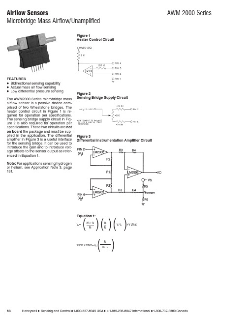
681-800-537-6945 USA 1-815-235-6847 International1-800-737-3360 CanadaFEATURESɀBidirectional sensing capability ɀActual mass air flow sensingɀLow differential pressure sensing The AWM2000 Series microbridge mass airflow sensor is a passive device com-prised of two Wheatstone bridges. The heater control circuit in Figure 1is re-quired for operation per specifications.The sensing bridge supply circuit in Fig-ure 2 is also required for operation per specifications. These two circuits are not on board the package and must be sup-plied in the application. The differential amplifier in Figure 3 is a useful interface for the sensing bridge. It can be used to introduce the gain and to introduce volt-age offsets to the sensor output as refer-enced in Equation 1.Note: For applications sensing hydrogen or helium, see Application Note 3, page 131.Figure 1Heater Control CircuitFigure 2Sensing Bridge Supply CircuitFigure 3Differential Instrumentation Amplifier CircuitEquation 1:V o ⍧2R 2+R 1R 4V 2-V 1+V offset()()()R 1R 3where V offset ⍧V S()R 6R 6+R 51-800-537-6945 USA 1-815-235-6847 International 1-800-737-3360 Canada 691. Output Voltage is ratiometric to supply voltage.2. Temperature shifts when sensing differential pressure correlates to the density change of the gas over temperature.See Application Note 1.3. Maximum allowable rate of flow change to prevent damage: 5.0 SLPM/1.0 sec.MOUNTING DIMENSIONS (for reference only)Airflow701-800-537-6945 USA 1-815-235-6847 International 1-800-737-3360 CanadaOUTPUT FLOW VS INTERCHANGEABILITY (Note 1)Performance Characteristics @10.0 ±0.01VDC, 25°C AWM2100V AWM2150VAWM2200V(Note 2)AWM2300V Press.Flow Nom.Tol.Press.Flow Nom.Tol.Flow Press.Nom.Tol.Press.Flow Nom.Tol.mBar sccm mV±mVȖBar sccm mV±mVsccm ⍯H 2O mV±mVmBar sccm mV±mV0.4920044.50 4.25533014.0 2.5120 4.0031.75 3.50 3.4100055.50 3.700.3515038.75 3.0036209.5 1.590 3.0026.75 2.50 2.480052.90 3.500.2110030.00 1.501710 5.0 1.560 2.0020.00 1.20 1.865050.00 2.500.095016.50 2.509.85 2.5 1.030 1.0011.20 1.800.8340042.50 3.000.000.00 1.007.44 2.0 1.000.000.001.000.3120029.20 3.20−0.09−50−16.50 4.50 6.23 1.5 1.0−30−1.00−11.20 3.0000.00 1.00−0.21−100−30.00 5.0052 1.0 1.0−60−2.00−20.00 3.30−0.31−200−28.9015.00−0.35−150−38.807.65 2.510.50.8−90−3.00−26.75 5.30−0.83−400−41.2026.00−0.49−200−44.509.75000.00.6−120−4.00−31.757.00−1.6−600−48.2029.50−9.8−5−2.5 2.0−2.4−800−52.2032.50−53−30−14.05.0−3.4−1000−55.0036.00Notes:1.Numbers in BOLD type indicate calibration type, mass flow or differential pressure.Tolerance values apply to calibration type only.2.Differential pressure calibrated devices are not recommended for flow e flow calibrated devices for flow measurement.OUTPUT CURVES。
马尔杰尔电子JCM2000系列DSL201和DSL401小型携带电钢机说明书
WARNING! - Important safety instructionsA.ALWAYS fit a good quality mains plug conforming to the latestB.S.I. standards where necessary (UK only).B.NEVER attempt to by-pass the fuses or fit ones of the incorrect value.C.NEVER attempt to replace fuses or valves with the amplifier connected to the mains.D.DO NOT attempt to remove the amplifier chassis, there are no user serviceable parts.E.Refer all servicing to qualified service personnel.Servicing is required when the apparatus has beendamaged in any way, such as the power supply cord or plug is damaged, liquid has been spilled or objects have fallen into the apparatus, the apparatus has been exposed to rain or moisture, does not operate normally or has been dropped.F.NEVER use an amplifier in damp or wet conditions.G.ALWAYS unplug this apparatus during lightning storms or when unused for long periods of time.H.Protect the power cord from being walked on or pinched particularly at plugs, convenience receptacles and atthe point where they exit from the apparatus.I.DO NOT switch the amplifier on without the loudspeaker connected.J.ENSURE that any extension cabinets used are of the correct impedance.K.PLEASE read this instruction manual carefully before switching on.Follow all instructions and heed all warnings.WARNING :This apparatus must be earthed!WARNING :Do not obstruct ventilation grille and always ensure free movement of air around the amplifier! USA ONLY - DO NOT defeat the purpose of the polarised or grounding type plug. A polarised plug has two blades with one wider than the other. A grounding type plug has two blades and a third grounding prong.The wide blade or the third prong are provided for your safety. When the provided plug does not fit into your outlet, consult an electrician for replacement of the obsolete outlet.KEEP THESE INSTRUCTIONSIntroductionWith the introduction of the Marshall JCM2000 range of DSL50 and 100 heads, the TSL100 head and the TSL122 combo, the quintessential definition of ultimate tone and usable features has been rewritten. This quartet of great amps has now spawned a new generation of compact, lower power combo amps, the DSL201 and DSL401, destined to be classics for both studio and session/club gigs.As the names imply these amps are 20 Watts and 40 Watts respectively, but as these are true valve amps, built to exacting standards, do not let the lower power ratingslull you into thinking that they are mere practice amps, as nothing could be further from the truth! The benefits of using a lower powered amp are many fold, not least that of being able to push the output valves harder for extra warmth at manageable volume levels. Just remember how many famous artists have used smaller amps to record those classic tracks and how many use lower powered amps on stage, to help balance the sound. Worried that your amp is great for the studio and small club, but not for bigger gigs? Well don’t, there are ways of making them sound much bigger than they really are. Just adding a Marshall 1960 4x12” is going to increase the spread and SPL of your sound, by simple physics. If not mic or D.I. through the PA. The onboard D.I. output of your DSL201 or 401 contains Marshalls acclaimed speaker emulation circuit, making accurate sounding D.I.ing as simple as plugging in a cable! Silent recording in your project studio? Again, use the speaker emulated D.I. output, only this time turn down the ‘output master’ volume control (which by the way, controls the apparent output power) to zero and still capture the full valve tone of your amp on tape (or disc!)Please note both models DSL201 and DSL401are described together, any model variations are indicated.7 User Hint- where you see text starting withthis sign, we have described some slighttechnical paraphenalia in order for you tounderstand what is going on inside your amp and we hope will help you in creating the tone that is best for you and your amp.1. Input JackAs most manuals state, plug your guitar in here.7 User Hint- Amusement aside, it isworthwhile remembering that you should use ahigh quality guitar lead to achieve optimumperformance. If you are unsure what constitutesa high quality lead then most good music storesshould be able to give you good advice, butremember, it may not be the cheapest one going!It is also worth pointing out here that how anamp sounds is VERY dependent on the type ofguitar you use. For instance, a guitar withhumbucker type pick-ups is not going to sound as open and clean as one with single coil typepick-ups, yet will provide that great mid rangebark that we are accustomed to for rock playing.2. Clean GainThis controls the preamp level of the cleanchannel, at lower settings the sound will be very clean and at higher settings the sound will start to ‘Crunch’ up in a traditional blues sort of way.In between, around midway, depending on what type of guitar you are using, you will find some great semi-clean/semi-crunch tones, just likethose great vintage amps that had minimalfeatures, but great tone.7 User Hint- there is a capacitor across thegain control that brightens up the tone when set to lower levels. This helps to ‘cut’ through atlow volumes and adds ‘twang’ to the tone. Asyou bring up the gain control the effect of thisdecreases and the tone becomes fatter. If youContinuing with the features of your amp, both the DSL201 and 401 have two totally independent, footswitchable channels, notably ‘Clean’ and ‘Overdrive’ which cover the whole range of tones from sparkly clean, through classic and modern‘Crunch’, through to super-saturated Lead Overdrive.On top of this, the DSL401 offers a three channel option by having the ability to (foot)switch between OD1 and OD2 - OD2 having even more gain than OD1 - in fact a staggering 20dB more! Thus giving the ability to switch from great clean to crunch and then to lead. Remember, the Clean channel not only does clean, it crunches up in a great traditional way too, just turn it up and drop the apparent output power (output master) down to a socially acceptable level.Rounding out the features, your DSL201 or 401 also has a parallel FX loop with a mix control and large spring ‘Sound Enhancements’ reverb, with footswitch facility (DSL401 only).It is important to mention here that your DSL201 or DSL401 use EL84 output valves, as opposed to either the 5881/6L6 or EL34 valves used in bigger Marshall amps. The EL84 is the classic output valve for smaller British style amps (and some U.S. ones too) and is a great valve to achieve superb tone at lower power levels. Normally they are used in a very simple circuit that features no negative feedback and are run in the cathode biased mode which gets close to them being run in class A, which makes for a very squashy compressed tone, as typified in the VOX AC30 for instance. Whilst this mode is great for these classic amps, we felt that this simple operating mode limited the amount of versatility required from an amp as diverse as the DSL201 & 401, in this modern age. Therefore, after careful study of how these classic amps worked and how the bigger Marshall’s worked, a fresh design that covers a broader spectrum of tones has been incorporated into theDSL201 and 401. We feel that it does it with great style.find the tone too thin with the gain control down either take some of the high end off with thetreble control, or alternatively, bring the cleangain control up until you achieve the depth oftone you want and then control the volume ofthe amp with the ‘master volume’ control.3. Clean Treble, Mid, BassThese controls vary the E.Q. and voicing of theClean channel.7 User Hint - These controls are early on in theamplifier chain and as such not only control the tone of the Clean channel, but also how the clean channel reacts ‘gain’ wise. For instance, if themid control is advanced (especially with higher gain control settings) the sound will becomemore ‘singing’ in a blues/traditional rock kind of way. But if the mid control is backed offtowards (or even) zero the gain emphasis isplaced on the treble and bass controls and gives more to work on, especially on cleaner, lowergain settings, as would be the case for country,jazz, or good old chord strumming.A good starting point is to set these threecontrols to their ‘midway’ position and byexperimenting with the ‘feel’ of how theyinteract with the amp, build up a wide palette of tones for future use.4. Channel SwitchingThe channels of your DSL201 or DSL401 caneither be switched from the front panel, or via an external footswitch - connection of thefootswitch is described later.DSL201 - The front panel switchingarrangement consists of two LEDs and a singlepushswitch, to switch between either the clean(Green LED) or Overdrive channels (Red LED).Switch out is Clean, switch in is Overdrive.DSL401 - Here the front panel switchingarrangement consists of three LEDs (Green =Clean, Yellow = OD1, Red = OD2) and twopushswitches, marked CLN/OD and OD1/OD2.To select Clean the switch marked CLN/ODmust be released to its out position (Green LED will be on). To select either OD1 or OD2, push the CLN/OD switch in and select either OD1 or OD2 by pushing or releasing the switch marked OD1/OD2 and the appropriate Yellow or RedLED will illuminate. To revert back to Clean,release the CLN/OD switch once more. Do not worry, you do not have to go through OD1 toreach OD2, these channels can be pre-selected.7 User Hint- These functions are repeated onthe footswitch. Remember that plugging thefootswitch into the amp will override the frontpanel pushswitches.5. Overdrive GainThis controls the amount of gain drive available for the overdrive channel, from mildly almostclean crunch to super-saturated overdrive,depending where this control is set, i.e. lower is less and higher is more. Wherever this control is set is going to give you a wide palette of tones to work with, depending on the type of guitar, EQsettings, how hard you push the power amp, etc.Note: the difference between OD1 and OD2(DSL401 only) is approx 20dB more gain onOD2. The DSL201 is preset to the gain levels of OD2 and does not have the OD1 facility.7 User Hint- Due to the immense amount ofgain and saturation available on the preamp ofthe DSL401, particularly when using high output humbucker pick-ups, the 20dB differencebetween OD1 and OD2 may become lessapparent. In this case, back off the settings ofthe gain control slightly until the differencebecomes more useable again.7 User Hint- One of the beauties of using alower power amp is that it makes the power amp distortion more easy to use and by lowering the input gain control and bringing up the channelvolume control will give you a whole new loadof tones to play with, as well as making the amp run quieter, especially if you use the ability ofthe ‘master volume’ to emulate a lower powered amp.6. Overdrive VolumeThis control adjusts the level of sound comingout of the overdrive preamp channel and allows you to balance it against the Clean channel.7 User Hint- To achieve the normal Marshallstyle heavy rock ‘punch & crunch’ especially at lower volume levels, this control should be used to keep the volume down and the output Master Volume should be kept higher. To achieve asquashier type tone, great for lead work, then use this control higher and bring the level down onthe output Master Volume.7 User Hint- When using the less gain/morelevel way of driving the power stage, keep theoverdrive gain low and use this volume controlto drive the power amp.7. Overdrive Treble, Middle, BassAs opposed to the ‘Clean’ channel, thesecontrols are placed after the distortion generating circuitry of your amp and as such affect thetexture of the tone, rather than the gain of thechannel, especially when using high levels ofpreamp gain.7 User Hint- Although many textures areavailable from this relatively simpleconfiguration, a good starting point (again) is to set everything midway. For a more modernheavy’ tone, turn the mid control down andboost the treble and bass. For a more classic‘rock’ tone bring back the mids and bring thetreble and bass down a bit.7 User Hint- When using the less gain / morevolume approach, the tone controls can be used to help ‘push’ the power amp for a more refined tone.8. Master FX MixThis controls the balance of the return from the parallel FX loop (see rear panel details forconnection) with the amps direct signal.7 User Hint- As the FX loop is of the parallelkind, this is where you should use time delayeffects (i.e. echo, reverb, pitch shifting, chorus, etc.). For optimum use the direct signal in your processor should be turned to zero so that onlythe effect signal is returned to the amp, this way the tone integrity of the direct amp signal isunimpaired.9. Master ReverbThis controls the level of the internal springreverb circuitry from a slight shimmer to acavernous depth. DSL401 only - the reverb has the facility of being footswitchable via the rearpanel socket and optional PEDL-10013footswitch.10. Master VolumeApart from the obvious function of being themaster level control for the whole amp(regulating the output volume of both the clean and the overdrive channels), this control actually affects the apparent power level of the poweramp section itself. This means that, at lowersettings, the amp acts and feels like an evenlower powered amp, along with the kind ofsmooth saturation that you get from pushing apower amp into distortion.7 User Hint- As the (rear panel mounted)speaker emulated D.I. output is derived from this circuit you can balance the sound coming out of the loudspeaker from zero to full, whilstmaintaining a constant level out of the D.I.output and enjoy the tonal qualities of a push-pull valve output stage - ideal for silentrecording, direct to the desk.11. Standby SwitchThis turns the high voltage feed to operate thevalves on and off.7 User Hint- This switch should be used for(a) allowing the amp to warm up before turningthe Standby on (at least a minute - preferably 2/3 minutes if possible) and (b) turn the Standbyswitch off when taking a break (rather thanturning off the whole amp), thereby keepingyour amp at the ‘ready’, without waiting for it to warm up again. Remember to do these twosimple rules and your valves will love you for it and should last an awful lot longer beforereplacement is needed.12. Power SwitchThis turns the mains electricity that feeds youramp on and off. As stated before, turn thisswitch on for at least a minute or two beforeturning the Standby on, to allow your amp towarm up.7 User Hint- For environmental reasons atleast, if leaving your amp for more than a normal gig type break or so, turn your amp off at thisswitch, it will save electricity. Also, if leavingyour amp unused for a long time, alwaysremember to disconnect your amp’s power cord from the mains supply, at the very least it willprevent someone else accidentily turning it onwithout realising.1. Channel Footswitch JackThis socket takes the jack connected to the lead of the channel change footswitch(CLEAN/OVERDRIVE - DSL201, CLN/OD & OD1/OD2 - DSL401).2. Reverb Footswitch -(DSL401 only)Takes the optional footswitch (PEDL-10013) to remotely control the reverb function.3. FX Loop Send JackConnects the DSL amp to the input of theexternal FX processor.4. FX Loop Return JackConnects the output of the external FX processor back into the DSL amp circuit.5. Speaker Emulated D.I. Out JackLine level, emulated output signal forconnection into PA or recording Mixing Desksetc.6. Loudspeaker Output Select -(DSL401 Only)This switch selects the output impedance of the amplifier for either 8 or 16 ohm use, to match to alternate speaker systems. Although more onthis will be covered later, it is important toremember that the internal loudspeaker is 16ohms and that the amp must be set to match that(16 ohms).7. Loudspeaker Output JacksOne (1) only on DSL201, two (2) on DSL401.These are identified by having RED jack socket nuts and connect the amplifier output to eitherthe internal (or an external) loudspeaker system.WARNING! At no time must the amplifier beallowed to run with no loudspeaker (orappropriate loudspeaker type load) connected to its output. Otherwise serious and expensivedamage may occur.8. H.T. Fuse - See specifications for correct valueThis fuse protects your amp in the case of a fault occurring with any of the high voltage circuit of your amp. The usual reason for this to blow iswhen an output valve has become faulty.9. Mains InputUse the supplied power cord to connect youramp to the mains supply.10. Mains Fuse - See specifications for correct valueThis fuse provides overall safety protection inthe case of your amplifier developing a majorelectrical fault.7 User Hint- The fuses fitted to your amp arethere to provide you with safety protection in the case of a fault developing. If they blow it means something is wrong, usually a valve is gettingold, but under no circumstances fit a fuse of adifferent value to stop it from blowing, as thiscould be very expensive in terms of safety andcost. Remember, if a fuse blows, it has blownfor a reason.LOUDSPEAKER SYSTEMSThe DSL201 and DSL401 combo amps are each fitted with a Marshall designed 12” loudspeaker, each one developed to work with your amp toproduce the great tone that you expect from aMarshall amp. The 1x12” format makes for avery highly portable package that works great in most circumstances. However, if you require a bigger sound, or just a different one, there arenumerous cabinets manufactured by Marshallthat will interface with your DSL combo, withultimate ease.The DSL201 is fitted with a single loudspeakersocket preset at an impedance of 16 ohms, which is normally plugged into the internal 16 ohm 12”loudspeaker. To use an external loudspeaker,just unplug the internal speaker and plug intoyour external cabinet (this must be 16 ohmsonly), for instance, a Marshall 1960 4x12”.The DSL401 is fitted with two parallel wiredloudspeaker jack sockets and a selector to switch between the normal 16 ohms (to suit the internal speaker) or 8 ohms. This makes the choice ofextension cabinets even wider. For instance, not only could you use a Marshall 1960 4x12” cab, with or without the internal speaker (set amp to8 ohms if using both, keep on 16 ohms if usingwithout internal speaker), but you could alsomake the choice of various Marshall 1x12” or2x12” extension cabs. But always make surethat the output selector is set correctly !i.e.1 x 16 ohm speaker = 16 ohm output2 x 16 ohm speaker = 8 ohm output1 x 8 ohm speaker = 8 ohm outputWARNING! Never operate your DSL valveamp without a loudspeaker, or suitableloudspeaker type load, connected to the output,even when using the output Master Volume setto zero for silent recording. Otherwiseexpensive damage may occur!USING EFFECTS SYSTEMSYour DSL combo amp is fitted with parallel FX Loop, this is placed after the gain and distortion parts of the preamp and is the ideal place forinserting time varying effects, such as delay,digital reverb, chorus, pitch shifting, etc. Bybeing a parallel loop, this means that the directsignal is kept within the DSL’s circuit andtherefore your tone is not degraded by sending it outside the amp. To use the loop connect youreffects processor (rack type units are better atthis job) as described earlier, turn the effectsunits direct signal path off (the FX units manual will tell you how to do this), set up the unit togive you the effect you require and then balance your direct sound and effected sound using theFX MIX control on the front of your amp. Easy!Floor type effects stomp boxes are designed towork in between a guitar and the input of an amp and should not be used in a parallel loop,otherwise some very weird and undesired effects could occur. For their best use, use them where they are designed to go.DSL201 SPECIFICATIONSPower Output - 20 Watts RMS into 16 ohmsValve complement - 4 x ECC83/12AX7 and 2 x EL84Loudspeaker Type - 12” 16 ohm 50 Watt Model SPKR-00072Mains Requirement - Preset for 117V~60Hz or 230V~50HzOther variations to special order - see local distributor for information.Mains Fuse - T2A- 117V or T1A- 230VH.T. Fuse - T250mADSL401 SPECIFICATIONSPower Output - 40 Watts RMS into 8 or 16 ohmsValve complement - 4 x ECC83/12AX7 and 4 x EL84Loudspeaker Type - 12” 16 ohm 100 Watt Model SPKR-00068Mains Requirement - Preset for 117V~60Hz or 230V~50HzOther variations to special order - see local distributor for information.Mains Fuse - T2A- 117V or T1A- 230VH.T. Fuse - T315mA。
AKG WMS470 UHF 无线麦克风系统说明书
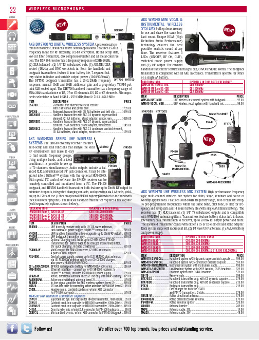
22Follow us!AKG WMS470 UHF WIREL agile multi-channel wireless mic system for clubs, stage, seminars and house of worship applications. Features 30Hz-20kHz frequency range, auto frequency setup, 16 pre-programmed frequencies within the same band, pilot tone, IR link for fre-quency and setup data and 14 hours battery life (with single AA lithium battery). The receiver has (1) XLR balanced, (1) 1/4" TS unbalanced outputs and is compatible with WMS4500 antenna splitters. Transmitters feature battery status info in hours, low battery data transmission to receiver, up to 50 mW RF output power and more. The handheld transmitter comes with either a C5 or D5 element and stand adapter. Each system ships with rackmount kit, (2) 1/4 wave UHF antennas, (1) AA LR6 battery and power supply.ORDERING INFO: WMS470 BAND 1 WMS470 BAND 7 WMS470 BAND 8 WMS470 BAND 9 ITEM DESCRIPTION WMS470-D5/VOCAL .........Handheld system w/D5 dynamic supercardioid capsule .......WMS470-C5/VOCAL .........Handheld system w/C5 condenser cardioid capsule .............WMS470-INSTRUMENTAL ..Instrumental system with instrument cable WMS470-PRESENTER v/Headmic system with CK99 lavalier, C555 headmic ......WMS470-SPORT ..............Headmic system with C544L headmic SR470 .............................Receiver only .........................................................................HT470/C5 ........................Handheld transmitter only, with C5 dynamic capsule HT470/D5 ........................Handheld transmitter only, with D5 condenser capsule PT470..............................Bodypack transmitter only CU400 .............................Fast charger for both the HT470 and PT470 transmitters, 2 slots SRA2B-W .........................Active directional antenna.....................................................RA4000B/W .....................Active omnidirectional antenna PS4000-W .......................Active antenna splitter AB4000 ...........................Antenna booster ....................................................................MKPS ...............................Antenna cable, 2ft MKA20 .............................Antenna cable, 20ft ESStechnology ensures the bestswitched mode power supplyN E W !HT470/D5C544L C555WMS470-INSTRUMENTAL WMS470-PRESENTER WMS470-SPORTPT470CK99PT470SR470We offer over 700 top brands, low prices and outstanding service.A professional sys-tem for broadcast, installed and live sound applications. Features 155MHz frequency range for RF flexibility, 512-bit encryption, IR link setup data, low-cut filter, 3-band EQ, dbx compressor/limiter and all metal construc-N E W !DSR700AKG WMS4500 SERIES UHF WIRE ESSThe SR4500 diversity receiver featuresauto-setup and scan functions that analyze the local RF environment and make it easyto find usable frequency groups.grated into a HiQnet™ system with the optional HUB4000Q.With special PC control software the SR4500 receiver can beremotely controlled and monitored from a PC. The PT4500bodypack, and HT4500 handheld transmitter both feature up to 50mW RF output to minimize dropouts, integrated charging contacts, and operation via 2 AA cells, yield-ing up to 15hrs of use (12hrs on optional BP4000 battery pack which is included with the CU4000 charging unit). The HT4500 handheld transmitter requires a mic capsule (sold separately; options shown below).OPERATES IN THIS RANGE:WMS4500 Band 1, TVCH 44-48 650.100-680.000MHzWMS4500 Band 2, TVCH 19-23 500.000-530.000MHzWMS4500 Band 3, TVCH 30-35 570.000-600.000MHzITEM DESCRIPTION PRICE ..................UHF diversity receiver only, with (2) 1/4-wave antennas,rack hardware, power supply, HiQNet™ compatible ......................749.00...................UHF handheld transmitter only (no capsule), up to 50mW RF output ..599.00...................UHF bodypack transmitter only .......................................................599.00..................Optional charging unit, holds up to (2) HT4500 or PT4500transmitters for battery back to be charged inside transmitter,1hr quick charging, includes 2 batteries .......................................569.00.............Multi-coupler for SR4500 receiver, (2) BNC antenna in,4 pairs of BNC outputs ...................................................................529.00................Central power supply, powers up to (12) SR4500 plus antennasvia (3) PS4000W antenna splitters or (3) CU4000 chargers,also powers HPA4000/HUB4000Q ...................................................479.00.BP4000 rechargeable battery for WMS4000/4500 series ...............116.64..............Ethernet interface – connect up to (8) SR4500 receivers toHiQnet™ network, includes PSU01/4000 power supply ...............1199.00................Active, directional antenna (need 2) use only with MKA5 cabling ..379.00...........Active omni wideband antenna (need 2) ........................................179.00 ..................In-line signal amplifier for AKG wireless systems (need 2) ............249.00...................66' low-loss cable for connecting active antennas to PS4000W (need 2) .49.00.....................Headworn mic, cardioid condenser w/mini XLR connectorfor PT4500 bodypack ......................................................................179.00HT4500 UHF Handheld Transmitter Capsules ..................Supercardioid dyn. mic capsule for HT4500 transmitter, 70Hz-20kHz ...99.00 ..................Cardioid cond. mic capsule for HT4500 transmitter, 65Hz-20kHz ..199.00 ..............Cardioid cond. mic capsule for HT4500 transmitter, 20Hz-20kHz ..349.00 ...................Omni lavalier mic w/mini XLR connector for PT4500 bodypack ........99.00 .................Mini cardioid lav mic, w/mini XLR connector for PT4500 bodypack ..299.00SR4500PT450023AUDIO-TECHNICA ARTIST ELITE SERIES FREQUENCY AGILE UHF WIRELESS SYSTEMS The AEW 4000 single channel and AEW 5000 dual channel systems feature 996 selectable UHF channels per band with True Diversity, dual compander circuitry, Tone Lok™ squelch, multiple channel coordination, highly visible white-on-blue LCD displays, and Intelliscan™, which finds and sets the best available frequencies on all linked receivers. Stores up to 5 presets with names. Bodypack transmitters feature locking battery doors. The AEW 3000 receiver has XLR and 1/4" TS outputs as well as 1/4" headphone out. The AEW 5000 features an onboard Ethernet interface for monitoring/controlling system parameters (includes software), XLR, 1/4" TRS and 1/4" headphone out. (Models shown below are in the “AD” band. For the “AC” band, replace the “AD” with “AC” at end of part number.) Please call for assistance in configuring systems.ORDERING INFO: OPERATES IN THIS RANGE:AC band, TVCH 25-30 541.500-566.375 MHzAD band, TVCH 44-49 655.500-680.375 MHzITEM DESCRIPTION PRICE Single-Channel UHF SystemsAEW-4110AD ........Bodypack system, no mic ..................................................................899.00AEW-4230AD ........Handheld system w/AEW-T3300a cardioid condenser mic ..............1119.00AEW-4240AD ........Handheld system w/AEW-T4100a cardioid dynamic mic...................969.00AEW-4250AD ........Handheld system w/AEW-T5400a cardioid condenser mic ..............1289.00AEW-4260AD ........Handheld system w/AEW-T6100a hypercardioid dynamic mic ..........969.00AEW-4313AD bo system w/1 bodypack, (no lapel mic),& AEW-T3300a HH ..........................................................................1479.00Dual-Channel UHF Systems (partial listing, more combo systems available)AEW-5244AD ........Dual-handheld system w/2 AEW-T4100a cardioid dynamic mics ...2939.00AEW-5255AD ........Dual-handheld system w/2 AEW-T5400a cardioid condenser mics ......CALL AEW-5266AD ........Dual-handheld system w/2 AEW-T6100ahypercardioid dynamic mics ...........................................................2939.00AEW-5313AD ........Dual-combo system w/1 bodypack,(no lapel mic) & 1 AEW-T3300a HH ................................................3119.00AEW-5413AD ........Dual-combo system w/2 bodypacks,(no lapel mic) & 2 AEW-T3300a HH ......................................................CALLComponents (partial listing)AEW-R4100D ........Single-channel UHF diversity receiver only .......................................669.00AEW-R5200D ........Dual-channel UHF diversity receiver only ........................................2129.00AEW-T1000AD ......Bodypack transmitter only for 4000/5000 series ..............................439.00AT8628A ...............Joining plate for two 4000/5000 series receivers ................................20.94AKG PERCEPTION SERIES UHF WIREL ESS The SR45 receiver features XLR and 1/4" jack outputs, 8 selectable frequencies, up to 30MHz bandwidth selection, as well as adjustable squelch threshold and audio level controls. The PT45 bodypack is compact, has 10mW of RF output, and the battery compartment cover doubles as a tool for setting input gain. The PT45 bodypack, and HT45 handheld transmitters offer up to 8 hours of operation on a single AA cell.ORDERING INFO OPERATES IN THIS RANGE:Default "A" Band 530.025-559.000 MHzITEM DESCRIPTION PRICE PERCEPTION-PRES-SET valier system w/CK99L cardioid lapel mic ...................299.00PERCEPTION-INST-SET .........Instrument system w/MKG-L guitar cable(mini-XLR to 1/4") ...........................................................249.00PERCEPTION-SPORT-SET ......Headworn system w/C544L cardioid, condenser mic .......299.00PERCEPTION-VOCAL-SET ......Handheld system w/HT45 cardioid, dynamic mic ............249.00HT45MKG-LSR45PT45C544L CK99LAUDIO-TECHNICA 2000 SERIES UHF24Follow us!AUDIO-TECHNICA FREEWAY 700able frequency-coordinated channels.ously under ideal conditions. The ATW-R700 diversity receiver has a button for KAL TMAN CREATIONS INVISIBL E WAVES RF SPECTRUM ANAL YZER SOFTWARE This software program is a PC-based RF spectrum analyzer that auto-matically charts open white space to aid those operating wireless mic systems, in-ear monitors, etc. Software features include split-screen displays, priority monitored frequencies, instant-save custom profiles, logging with date & time stamps, etc. All system packages include an electronics/receiver package, built-in rechargeable bat-tery pack, AC adapter/charger, multiple antennas, USB-PC cable and a carrying case.ITEM DESCRIPTION PRICE IW1800 ..........RF Spectrum Analyzer Software for VHF/UHF analysis, 9kHz-1.8GHz ....1554.80IW3500 ..........RF Spectrum Analyzer Software, 9kHz-3.5GHz ......................................1847.30LAPTOP NOT INCLUDED.ESS MICROPHONE ULM18HM-3R300-RX BP-300Our Sales Pros will provide you with the solutions you need.26Follow us!ECTROSONICS R400 STUDIO SMQVSMVMM400CLMA RMUTHM Shop anytime. Buy online. Go to 27WIRELESS AUDIO LECTROSONICS LECTROSONICS UCR401XD-V30L INE 6 XD-V30/XD-V70 SERIES DIGITAL WIREL ESS SYSTEMS These sys-tems commonly offer 24bit conversion, a frequency response of 10Hz-20kHz, latency of less than 4ms, up to >120dB of dynamic range (XD-V70L model), and do not utilize a compander. They utilize two proprietary technologies – DCL™ (Digital Channel Lock), which provides an encoded digital transmission that ensures against all types of RF interference from interrupting your audio, and PDP™ (Proprietary Data Placement) that incorporates a hybrid frequency-hopping spread-spectrum technology. Each user channel is split into 4 frequencies before being transmitted. The receiver reassembles the signal and the result is reliable operation, even in hostile RF environments. The XD-V30 series has 6 channels always available, a 100' range (line-of-sight), a polycar-bonate desktop receiver chassis, internal antennas, and metal transmitter bodies. The handheld transmitter has modeling based on the Shure® SM58® microphone. The XD-V70 series has 12 channels always available, a 300' range (line-of-sight), metal 1/2RU receiver and transmitter bodies, and built-in loop-through antenna distribution system. The V70 handheld transmitter has 7 total mic models (Line 6 DC7, Shure® SM58®, Shure® Beta 58A, Sennheiser® e835, Audio-Technica® AE4100, Audix® OM5, and Electro Voice® N/D767). V70 series systems ship with rack hardware, and antenna front-mount kit w/necessary accessories. All V30/V70 series transmitters operate on 2 AA cells (2 included), for up to 8 hours of operation.ORDERING INFO: OPERATES AT:Default Band 2.4GHzITEM DESCRIPTION PRICE XD-V30 ...........Handheld system, 6 channels, table-top, w/cardioid capsule ................349.99XD-V30L .........Beltpack system, 6 channels, table-top, w/lav mic, tie clip/windscreen ...349.99XD-V30HS .......Headworn system, 6 channels, table-top,w/uni-directional headmic, windscreen ..................................................379.99XD-V70 ...........Handheld system, 12 channels, 1/2RU w/kit, cardioid capsule ..............499.99XD-V70L .........Beltpack system, 12 channels, 1/2RU w/kit,w/lav mic, tie clip/windscreen ................................................................499.99XD-V70HS .......Headworn system, 12 channels, 1/2RU w/kit,w/omni headmic, windscreen .................................................................579.99HS70 ..............Headset mic for XD-V70 beltpack, comes in beige or black ...................139.99XD-V70ESSSYSTEM FOR TEST & MEASUREMENTL INE 6 REL AY SERIES The G30 & G50 are stompbox style systems, while the G90 is a 1RU receiver style system. They all commonly feature Line 6’s proprietary companderless digital audio transmission in the 2.4GH z carrier frequency. Relay systems use unique-ly addressed and encoded signals that are impervi-ous to WiFi networks and Bluetooth® signals. They produce full-range tones, 10Hz-20kHz frequency response, are low noise with up to 120dB dynamic range, and provide studio-quality resolution with 24-bit A/D conver-sion. The G30 has a polycarbonate style chassis, 118dB dynamic range, 6 compatible channels, and up to 100' operating range. The bodypack has a 1/4" TS input and oper-ates on 2xAA cells for up to 8hrs use. The receiver has a 1/4" output and controls for channel select and cable tone simulator. The G50 upgrades to a metal chassis, 120dB dynamic range, 12 compatible channels, and up to 200' operating range. The bodypack features a TA4F connection, LED power/audio status, and a LCD power/battery life display. The receiver has a 1/4" output, tuner-pass thru, and channel number/battery life LCD display. The G90 upgrades to a 300' operating range, XLR output, audio status/transmitter battery life/mute/RF LEDs, and a control for receiver setup. All Relay systems ship with transmitter, receiver, antennas (when applicable), guitar cable, power supply, and batteries.ORDERING INFO: OPERATES AT:Default Band 2.4GHz ITEM DESCRIPTION PRICE RELAY-G30 ...........6-channel 2.4GHz digital guitar wireless system w/stompbox receiver .........................................................................299.99RELAY-G50 ...........12-channel 2.4GHz digital guitar wireless system w/pro-stompbox receiver ...................................................................399.99RELAY-G90...........12-channel 2.4GHz digital guitar wireless system w/1RU receiver .......599.99G30G50G9028Follow us!ESS SYSTEMS tations or any other situation where intelligible speech z,01-HDEXEC-NMESS These are USB microphones z band, that are full duplex wireless up to 100', and encrypted for privacy. The mics themselves are available as a personal clip on, a desktop boundary type in cardioid or omni versions, or even a plug on unit for XLR dynamic mics. Each mic has a 2.5mm phone jack in for headphone or earphone monitoring. Internal rechargeable batteries provide 8 hours talk time. Up to 16 systems can operate together without interference. The base station receiver/charging unit (sold separately) has USB OS) without the need for special drivers (but do not include mics). RF armor versions have special shielding to eliminate REVOL ABS MICROPHONES FOR REVOL ABS SINGL E/DUAL HD, AND XLR TRANSMITTERCLIP-ON TABLETOP UNI TABLETOP OMNIANSMANN NIMH 1.2V RECHARGEABLE CELLS / CHARGING SYSTEMS FORWIRELESS SYSTEMS ITEM DESCRIPTION PRICE AA-RECHARGEABLES ........AA cell, 4-pack, 2850mAh, runs in wirelessssystems 10+ hrs, recycle 1000 times ....................................17.999VOLT-RECHARGEABLES ..9V, 1-pack, 250mAh, runs in wireless systems 4-6 hrs,recycle 1000 times .................................................................14.50ENERGY-8-PLUS ...............Desktop charger w/reconditioning, charges 2 9V’sand 6 AA/AAA’s, 3-year warranty............................................84.00PROFESSIONAL-16 ...........1RU charge station for up to 16AA cells (NiCD/NiMH),700mA charge current per cell, charge time 2-3 hours .......535.00PROFESSIONAL-8 .............1RU charge station for up to 8 9V cells, 75mA chargecurrent per cell, charge time 2 hours ...................................495.004000042...........................Underload capacity tester for alkaline cells and NiMHrechargeables in sizes AAA, AA, C, D and 9V. Indicators in25% steps – determination of the actual remaining cellcapacity; includes (1) 9V-battery; 3-year warranty ................24.99REVOL ABS SINGL E/DUAL HDThese systems use the same high definition audio, FOR MORE WIRELESS MICS, VISIT CHARGER BASE.PRICES SUBJECT TO CHANGE WITHOUT NOTICE. Call today or visit us online!。
达威仪器有限公司产品说明书

MODEL CHART
Model 12AD0 12AL0 14AD0 15VD0
12AD1 14AD1 12VD0-J1 14VD0-J1
Function 2 SPDT 2 SPDT (lever drive) 4 SPDT 2 SPDT and 4-20 mA position transmitter 2 SPDT 4 SPDT 2 SPDT 4 SPDT
Design Magnetห้องสมุดไป่ตู้c coupling Magnetic coupling Magnetic coupling Magnetic coupling
Magnetic coupling Magnetic coupling Magnetic coupling Magnetic coupling
Price Model $245.00 42AD0
Stainless Mounting Kit 1/4 turn actuator Manual 1/4 turn valves Linear control valves
Price $47.00
79.50 159.00
Mounting kits with drive yoke (see drawing), or slotted lever arm, bracket, fasteners and other stainless steel hardware fit over 2000 popular valves and actuators. A high strength spring tempered stainless steel drive yoke/coupling is tailored to fit securely to a specific valve or actuator stem. There is no slippage or binding. No special alignment fixtures are required due to switch offset design and yoke to stem engagement that makes installation a “snap”. Each kit is specially designed for a particular valve or actuator, making field mounting simple with standard tools. Please specify make and model of valve or actuator on order. Mounting kits can be used interchangeably with all models since external mounting features are identical. Rotary valves utilize direct drive couplings and a slotted lever drive is used with linear valves. Lever drives convert linear motion to rotary. Stainless steel visual indicators are standard for direct drive, automated quarter-turn valve applications.
Agilent N9330B手持线缆和天线测试仪 25MHz - 4.0GHz 技术概述说明书

Agilent N9330BHandheld Cable and Antenna Tester25 MHz - 4.0 GHzTechnical OverviewYour perfect solutionfor testing cables andantennas in today’scommunication networksToday, the increasing range of wireless applications provides end users on the move with faster and more diverse services.Broadband mobile data and telephony are now becoming ubiquitous, with coverage in most urban and many rural areas.The number of base stations (BTS) needing fast, efficient installation continues to grow.Moreover, the vast numbers of existing installed base stations need periodic maintenance and, from time to time, trouble shooting and repair.Whether you do your ownmaintenance test or rely on third-party contractors, you need well-maintained antenna networks and cables to ensure:g Better voice and data quality g Fewer dropped calls g Less dropped linksAn efficient and effective cable and antenna tester is an essential basic test tool for network engineers and technicians for wireless network installation and maintenance.Key measurements Frequency domain[[[[g Return loss vs. Frequency [[[[g VSWR vs. Frequency [[[[g Cable loss test Distance to fault (DTF)[[[[g[Return loss vs. Distance [[[[g[[[[[g[VSWR vs. Fault locationDistance Easy to use and convenient to carry to any site.N9330B ApplicationsWireless service providers: base station cable & antenna system I&MAerospace and defense: radio and radar cable & antenna system I&MBroadcasting and radio links: cable & antenna system I&M Utilities, emergency and security servicesContractors for all the above•••••Verify performance and trouble-shoot base station cable and antenna systems: test wide band or narrow band from 25MHz to 4GHz:g New site installation and deploymentg Routine maintenance g Trouble shooting2Ensure the reliability of your cable andantenna systemEarly identification of potential problemsDeteriorating cable and antenna conditions, such as a loose or corroded connector, a pinched or restricted cable, or damaged lightning arrestors cause measurable RF impedance changes. Slight changes in VSWR, power loss and antenna bandwidth drift are early indications of system deterioration.Fast measurement speed means your technicians can evaluate one of the trouble spots in a matter of minutes.N9330B speeds up installation of cables and antennas at new site, too.Whatever your tasks, speed is important, with N9330B you can test more sites perday. And USB data storage lets you save all of the results for post-test analysis.You will find the Agilent N9330B tester useful and reliable, in rugged fieldenvironments for rapid installation of a new cellular network infrastructure, 2-way radio communication system or any type of communication system.Early identification of potential problemsDistance-To-Fault testing uses frequency domain reflectrometry (FDR) techniques that readily detects and locates theses slight changes in RF impedance. With routine DTF testing as part of apreventative maintenance plan, you can find and fix these problems before the system fails and repairs become costly. Agilent’s N9330B provides fast startupseconds.It's small size and light weight make it field use and all weather conditions.3A fast job, well doneA busy technician needs fast tester setup, quick calibration, and a straightforward, repeatable test procedure. Agilent N9330B gives you:Easier operationThe Agilent N9330B is easy to use, so itminimizes the need for training.Technicianswill get up to speed fast - and get theirwork done quickly.Smart, fast calibrationAt the start of any new test setup, a three-step calibration is necessary, using an open,a short, and a calibrated test load.The most accurate calibration method isto use mechanical calibration standards, anoptional special 'T-combo' open/shot/load,makes it easy for use in the field.For fast and automatic calibration, youcan choose the N9330B-203electroniccalibrator. Simply connect the electroniccalibrator and press a key to run theelectronic calibration.Well organized front-panel with more hard buttonsand function keys for faster access to essential testfunctions.'T-combo'open/short/50 ohm loadElectronic calibrator4USB memory stick supportUSB connectivity for PC softwareFast startup timeAuto calibrationTest set-up recallMore direct-access hard keysRapid cursor control and markermovement using scroll knobEasy data storageCustomized, unmistakably nameddata files and auto-sequential filenamingComprehensive results saved in aan easy-to-use formatAuto pass/fail test comparisonsN9330B-203The optimum combination of hardkeysand softkeys provides an intuitiveinterface for all measurements.The most-used functions are convenientlyselectable, via large, front-panel keys.The front-panel knob provides a simplescroll function, allowing rapid cursormovement to access data points acrossscan displays, or data entries.N9330B optimized usability:Long battery lifeModern USB connectivitySunlight-viewable LCDMulti-language UIRugged design for field usePowerful functions:Smart and fast electroniccalibratorPowerful post analysis PCsoftwareUse sensible archive file names related to each site tested The N9330B lets you choose meaningful names for your stored data: names that you customize and relate to your site. You no longer have to tolerate anonymous file names with no linkage to your site. It is easy to recognise and recall archived data files without the need for cross-referencing.And you can use sequential file names as you store successive files. Powerful PC based post analysis softwareEffective cable and antenna testing is more than just the measurements.Agilent provides a powerful PCbased post-analysis tool. This software tool, standard with every Agilent N9330B, provides trace analysis, trace comparison,customized reports and data file management.The USB connection makes it fast and easy to transfer the measurement data to the PC for analysis.Store data and setup configuration For fast instrument set up, you can store up to 15 stored configurations in the internal memory.When you take the tester out into the field, and have a large number of sites and installations to check, you need sufficient storage capacity for previous, historic data. The internal memory stores up to 200 traces, and you can save screen images.If you need even more, simply use a USB memory stick for external storage of configurations, traces and screen images.Pressing the front panel “Save” function key displays the soft key, “Save DATA as”. This then allows you to enter an appropriate file name.Take a closer look and see where Agilent puts the emphasis on usabilitySubsequently, press the “Save DATA” soft key,each new file name automatically increments, as in example:CHICAG_SITE2, CHICAG_SITE3,...5Fast export of data via USB interface6Agilent TechnologiesN9330B Handheld Cable and Antenna TesterAgilent TechnologiesN9330B Handheld Cable and Antenna TesterModern USB connectivity for both remote controland memory stickRapid marker positioning to measurementpoints using the fast-scroll rotary controlEasy results comparison-fast recall of stored dataEasy access to most common tests andsettings using keypad7Agilent reliable field useTesting in the field means workingin remote locations and out in the open: sometimes carrying test equipment up towers, or possibly workingin small, cramped buildings with no direct access to AC power on site.You may have to test:under temperature extremes in bright sunlight or in the dark in poor weather conditions None of these is the bestoperating environment for precision electronic test equipment.Agilent designed the N9330B cable and antenna tester for all weather conditions.•••Outstanding display technology provides superior performance under the most demanding lighting conditionsCarry-case options provide safe, comfortable transportThe soft carrying case provides added protection. A convenient shoulder strap leaves hands free for carrying other tools and equipment, or for safe climbing of access towers and gangways.For further protection of the tester when storing or transporting it in more harsh environments, an optional hard transit case is available.The tester itself has a strong hand strap for a sure grip when carried without the case.See traces clearly indoors and outdoorsAs with all the newest Agilent portable field equipment, operating under challenging bright sunlight or other difficult natural lighting conditions is not a problem. The bright new 6.5’’ TFT display with resolution of 640 x 480 pixels provides a superior,bright and clear trace for indoor and outdoor use.8N e wBack-lit keys for night useThe new back-lit keys in the N9330B make it easy to see the keys clearly, even in the dark.The user can adjust the brightness of the keys and the duration of the key light, making it easy to use in light or dark, day or night.N ewLow-cost, with Agilent worldwide supportSuperior battery performance Earlier battery technology used in some There is often no convenient conventional AC power line connection available at remote BTS or antenna sites. portable testers allowed only limited tester operating time before needing recharging.Worldwide service support Of course, when you buy an Agilent tester,you are confident that should you need it you have the best worldwide support.Based on customer inputs, Agilent understands that good battery life is essential for remote, on-site testing.Agilent N9330B incorporates advanced battery pack technology with intelligent charging technology, to provide you with up to four hours of continuous use. When extended operation is necessary, you simply switch batteries which only takes seconds.The long-life lithium-ion batteries in the N9330B have no 'memory', which is an important improvement over earlier battery types.To maximise useful instrument test time when on site, each tester incorporatessmart power management to help conserve battery power.The Agilent N9330B Cable and Antenna Tester - The newest in Agilent’s lineup of low cost handheld instruments.9N9330B Handheld Cable and Antenna Tester SpecificationsT est functionsFrequency Range Frequency Resolution:Output Power:Measurement Speed:Number of Data Points:Return Loss :SWR:Cable Loss:Measurement Accuracy:Distance-to-Fault:Range:Resolution:Markers:User storage:GeneralDisplay:6.5" 640x480 transflective color LCD with adjustable backlightInstrument setup storage:Trace data storage:Screen images storage:up to 15up to 200 traces 10 screensSupport USB memory stick for instrument setup, trace data and screen image storage Resolution (meter)=(1.5 x 10 )x (Vp)/(f2-f1)HzWhere Vp is the cable's relative propagation velocity.where f2 is the stop frequency and f1 is start frequency.(Number of data points - 1) x Resolution Number of data points=521,261, or 131Vertical Range:Return Loss: 0.00 to 60.00 dB SWR 1.00 to 65.00> 42 dB corrected directivity after mechanical calibration Range:Resolution:0.00 to 30.00 dB 0.01 dBRange:Accuracy:Resolution: 1.00 to 65.00same as RL 0.01Range:Accuracy:D:RL:Resolution:0.00 to 60.00dBA=20×log10(1.1+10 +0.016×10 +10 )directivity of calibrator return loss value of DUT 0.01 dB (maximun): 521(selectable 521,261,131)<2 second / screen (full span,521 data point ) (CW sweep mode)(3.0 ms/data point,typically)0~-20 dBm100 KHz 25 MHz to 4.0 GHz Return loss SWR Cable lossDistance-to-fault(DTF)6Internal user flash memory:10(-(D-RL)/20)(-RL/20)(-3+RL/20)8> 38 dB corrected directivity after electronic calibrationElectromagnetic Compatibility:IEC 61326-1:1997+A1:CISPR 11:1990/EN 55011:IEC 61000-4-2:1995+A1:IEC 61000-4-3:IEC 61000-4-4:IEC 61000-4-5:IEC 61000-4-6:IEC 61000-4-11:Canada:Australia/New Zealand:1998/EN 61326-1:1997+A1:19981991 Group 1 Class A1998/EN 61000-4-2:1995(ESD 4kV CD,8kV AD)1995/EN 61000-4-3:1995(3V/m,80% AM)1995/EN 61000-4-4:1995(EFT 0.5kV line-line,1kV line-earth)1995/EN 61000-4-5:1995(Surge 0.5kV line-line,1kV line-earth)1996/EN 61000-4-6:1996(3V ,0.15~80 MHz,80% AM,power line)1994/EN 61000-4-11:1994(Dips 1 cycle,100%)ICES-001:1998AS/NZS 2064.1IEC 61010-1:Safety:2001/EN61010-1:2001,CSA C22.2 No.61010-1:2004,UL61010-1:2004Operating:Non-operating:Temperature:-10C to 50C ,humidity 85% or less-40C to +70C (Recommend the battery be stord separately below 0 C and above +40C for any prolonged non-operating storage period.)Environmental:According to Agilent Environmental Test Manual class OE, except TemperaturePower Supply External DC Input:+11 to +25 volt dc, 40W min.Internal battery:Rechargeable Lithium-ion battery. 4 hours operating timeSize(w x h x d):Weight:Dimensions:317mm x 207 mm x 69 mm (12.5 in x 8.1 in x 2.7 in)Net weight: 2.6 kg (5.73 lbs)Weight with battery: 2.9 kg (6.39 lbs)Input and output ports:RF Test Port:Maximum Input without Damage:USB master:USB slave:Type N,female,50 +25 dBm, ±50 VDC 1 x A plug 1 x B plug v1.1 protocol v1.1 protocolSoft carrying caseN9330B handheld cable and antenna testerRechargeable batteryPhase-stable extension cableAutomotive 12V DC adaptorElectronic calibratorT-combo'open/short/50 ohm loadHard transit case11Agilent Email Updates/find/emailupdates Get the latest information on the products and applications you select.Remove all doubtOur repair and calibration services will get your equipment back to you, performing like new, when promised. You will get full value out of your Agilent equipment throughout its lifetime.Your equipment will be serviced by Agilent-trained technicians using the latest factory calibration procedures, automated repair diagnostics and genuine parts. You will always have the utmost confidence in your measurements.Agilent offers a wide range of additional expert test and measurement services for your equipment, including initial start-up assistance , onsite education and training, as well as design, system integration, and project management.For more information on repair and calibration services, go to www. /find/remove all doubtFor more information on Agilent Technologies’ products, applications or services, please contact your local Agilent office. The complete list is available at:/find/contactus Phone or Fax United States:(tel) 800 829 4444(fax) 800 829 4433Canada :(tel) 877 894 4414(fax) 800 746 4866China:(tel) 800 810 0189(fax) 800 820 2816Europe:(tel) 31 20 547 2111Japan:(tel) (81) 426 56 7832(fax) (81) 426 56 7840Product specifications and descriptions in this document subject to change without notice.© Agilent Technologies, Inc. 2008Printed in USA, July 1, 20085989-8567ENOrdering InformationModel DescriptionNumberConnectorsN9330B25 MHz to 4 GHz Handheld Cable and Antenna TesterAccessories supplied as standard with the tester: • Soft carrying case • Rechargeable battery• AC-DC adaptor with power cord • USB cable• Quick-start Tutorial• Documentation CD (also includes measurement analysis PC software)Options201202203301302303BAT 1DC 1TC ADP ABA AB2Precision mechanical short/open/50 ohm load, DC to 4 GHz Precision mechanical short/open/50 ohm load, DC to 4 GHz Electronic calibratorPhase-stable extension cable 1.5 m Phase-stable extension cable 1.5 m Connector adaptor Spare battery pack BCG External battery charger Automotive 12V DC adaptor Hard transit case Spare AC-DC adaptorHard copy English User Guide Hard copy Chinese User GuideN-type (male)7/16 DIN (male)N-type (male)Type-N (male) to type-N (female)Type-N (male) to 7/16 DIN (female)Type-N (male) to 7/16 DIN (female)Warranty and service Standard warranty is one year.R-51B-001-3C1-year return-to-Agilent warranty extended to 3-yearsCalibrationAgilent calibration upfromt support plan, 3-year coverageR-51B-001-3Korea:(tel) (080) 769 0800(fax) (080) 769 0900Latin America:(tel) (305) 269 7500Taiwan:(tel) 0800 047 866(fax) 0800 286 331Other Asia Pacific Countries:(tel) (65) 6375 8100(fax) (65) 6755 0042Email:*****************Revised: 11/08/06。
摩克斯A MAR-2000系列产品介绍说明书
MAR-2000 SeriesOverviewAppearanceThe MAR-2000 is a compact, simple, and programmable RISC-based wireless mobile router with strong wireless routing capabilities. With a built-in GPS module, HSPA+ cellular and 802.11a/b/g/n wireless capabilities, independent power switches on its cellular module connectors, and high thermal tolerance, the MAR-2000 is compliant with a portion of EN 50155 specifications. The built-in 32 MB NOR Flash ROM and 512 MB SDRAM give you enough memory forinstalling your own application software, the 512 MB NAND Flash can be used to provide additional data storage, and the CompactFlash socket is available for adding more memory when needed. The built-in GPS module supports geo-fencing functionality, making it ideal for managing wireless connections in cross-WAN environments often associated with rolling stock and other vehicular applications.When a train travels to a different region, it often encounters switches that support different wireless interfaces, such as Wi-Fi, UMTS, and HSPA+. The MAR-2000 uses multiple-WAN support and backup functionality to ensure that your wireless connections are always available, stable, and reliable.As an added bonus, the MAR-2000 series includes wide temperature models designed to operate reliably in extreme environments with temperatures ranging from -25 to 70°C.Front ViewRear ViewDO x 4(Power, Programmable,Ready, Storage)10/100 Mbps LED Indicators x 4Pin AssignmentEthernet PortHardware SpecificationsComputerCPU: Intel XScale IXP435, 533 MHzUSB: USB 2.0 hosts x 2, type A connectorDRAM: DDR2 SDRAM, 512 MBFlash:• NOR Flash, 32 MB onboard to store OS• NAND Flash, 512 MB (1 GB max.) for OS file system, caching storage, and data loggerOS (pre-installed): Linux 3.8.13StorageStorage Expansion: CompactFlash (Type I/II) sockets x 1, up to 8 GB Ethernet InterfaceLAN: Auto-sensing 10/100 Mbps ports (M12) x 2Magnetic Isolation Protection: 1.5 kV, built inGPS Module (U-Blox LEA-6S)Receiver Types:• 50-channel U-blox 6 engine• GPS L1 C/A code• SBAS: WAAS, EGNOS, MSAS, GAGANAcquisition:• Cold starts: 28 s• Warm starts: 28 s• Aided starts: 1 s• Hot starts: 1 sSensitivity:• Tracking: -160 dBm• Reacquisition: -160 dBm• Cold starts: -147 dBmTiming Accuracy:• RMS: 30 ns• 99%: < 60 ns• Granularity: 21 nsAccuracy:• Position: 2.5 m CEP• SBAS: 2.0 m CEPProtocols: NMEA, UBX binary, 5 Hz max. update rate (ROM version) Time Pulse: 0.25 Hz to 1 kHzVelocity Accuracy: 0.1 m/sHeading Accuracy: 0.5 degreesA-GPS: Supports AssistNow Online and AssistNow Offline, OMA SUPL compliant Operational Limits: Velocity: 500 m/s (972 knots)Connector Type: TNCWLAN Module (Atheros AR9220)WAPN001: IEEE 802.11a/b/g/n wireless LAN module with TNC antenna connectorStandards: IEEE 802.11a/b/g/n for wireless LANConnector Type: QMA connectors (female type) x 2Mode: Client/APCellular Module (Cinterion PH8)Frequency Bands: GSM/GPRS/EDGE/UMTS/HSPA+Band Options:• Five-band UMTS (WCDMA/FDD)• 800/850/1900 AWS and 2100 MHz• Quad-band GSM: 850/900/1800/1900 MHzHSDPA/HSUPA Data Rates:DL: 3.6/7.2/14.4 Mbps; UL: 2.0/5.76 MbpsUMTS Data Rates:DL: 384 kbps (max.); UL:384 kbps (max.)EDGE Class 12:DL: 237 kbps (max.); UL: 237 kbps (max.)GPRS Class 12:DL: 85.6 kbps (max.); UL: 85.6 kbps (max.)Connector Type: QMA connector (female type)Serial InterfaceSerial Standards: RS-232/422/485 software-selectable ports (DB9) x 2Console Port: RS-232 (TxD, RxD, GND), 4-pin pin header output (115200, n, 8, 1)Serial Communication ParametersData Bits: 5, 6, 7, 8Stop Bits: 1, 1.5, 2Parity: None, Even, Odd, Space, MarkFlow Control: RTS/CTS, XON/XOFF, ADDC® (Automatic Data Direction Control) for RS-485Baudrate: 50 bps to 921.6 kbps (supports nonstandard baudrates; see user’s manual for details)Serial SignalsRS-232: TxD, RxD, DTR, DSR, RTS, CTS, DCD, GNDRS-422: TxD+, TxD-, RxD+, RxD-, GNDRS-485-4w: TxD+, TxD-, RxD+, RxD-, GNDRS-485-2w: Data+, Data-, GNDSoftware SpecificationsDigital InputInput Channels: DI x 4Input Voltage: 0 to 30 VDCDigital Input Levels for Dry Contacts: • Logic level 0: Close to GND • Logic level 1: OpenDigital Input Levels for Wet Contacts: • Logic level 0: +3 V max.• Logic level 1: +10 V to +30 V (COM to DI)Connector Type: 10-pin screw-fastened terminal block (4 points, COM, GND)Isolation: 2 kV optical isolationDigital OutputOutput Channels: DO x 4, sink typeOutput Current: 200 mA (max.) per channelOn-State Voltage: 24 VDC nominal, open collector to 30 VConnector Type: 10-pin screw-fastened terminal block (4 points, GND)LEDsSystem: Power, Ready, Storage, Programmable LAN: 10M x 2, 100M x 2 (on connector)Serial: TxD x 2, RxD x 2Reset Button: Supports “Reset to Factory Default”Physical CharacteristicsHousing: SECC sheet metal (1 mm)Weight: 1.2 kg (2.67 lb)Dimensions: 200 x 57 x 120 mm (7.87 x 2.24 x 4.72 in)Mounting: DIN rail, wallEnvironmental LimitsOperating Temperature: -25 to 70°C (-13 to 158°F)Storage Temperature: -40 to 80°C (-40 to 176°F)Ambient Relative Humidity: 5 to 95% (non-condensing)Anti-Vibration: IEC 61373 standard Anti-Shock: IEC 61373 standardPower RequirementsInput Voltage: 24 VDC (9 to 48 V), M12 connector Input Current: 833 mA @ 24 VDC Power Consumption: 20 WStandards and CertificationsSafety: UL 60950-1EMC: EN 55032 Class A, EN 61000-4-2, EN 61000-4-3, EN 61000-4-4, FCC Part 15 Subpart B Class ARail Traffic: EN 50155*, EN 50121-4, IEC 61373*Complies with a portion of EN 50155 specifications.ReliabilityAlert Tools: Built-in buzzer and RTC (real-time clock)Automatic Reboot Trigger: Built-in WDT (watchdog timer)MTBF (mean time between failures)Time:MAR-2002-T: 280,129 hrs MAR-2001-T: 350,609 hrsStandard: Telcordia (Bellcore) Standard TR/SRWarrantyWarranty Period: 5 years (does not apply to cellular module)Details: See /warrantyNote: These hardware specifications describe the embedded computer unit itself, but not its official accessories. In particular, the wide temperature specification does not apply to accessories such as power adapters and cables.LinuxOS: Linux 3.8.13Terminal Server (SSH): Provides secure encrypted communications between two untrusted hosts over an unsecure network File System: JFFS2, NFS, Ext2, Ext3, Ext4, UBIFSInternet Protocol Suite: TCP, UDP, IPv4, SNMPv2, ICMP, ARP, HTTP, CHAP, PAP, DHCP, NTP, PPPInternet Security: OpenVPN, IPTables Firewall, OpenSSLNetwork Service: Moxa’s Dynamic Routing and network management Web UIGPS: Uses gpsd, which is a daemon that receives data from a GPS receiver, and provides the data back to multiple applications such as Kismet or GPS navigation software Application Development Software:• Moxa API Library (Moxa serial I/O control, Moxa DI/DO API) • GNU C/C++ cross-compiler, supports EABI • GNU C library• GDB source-level debugging serverSoftware Protection: Encryption tool for user executable files (based on patented Moxa technology)Ordering InformationM12 Connectors (can be purchased separately)M12A-5P-IP68: Field-installaable A-coded screw-fastened power connector, 5-pin female M12 connector, IP68-ratedM12D-4P-IP68: Field-installable D-coded screw-fastened Ethernet connector, 4-pin male M12 connector, IP68-ratedM12 Cables (can be purchased separately)CBL-M12(FF5P)/Open-100 IP67: 1-meter A-coded M12-to-5-pin power cable, 5-pin female M12 connector, IP67-ratedCBL-M12D(MM4P)/RJ45-100 IP67: 1-meter D-coded M12-to-RJ45 Cat-5C UTP Ethernet cable, 4-pin male M12 connector, IP67-ratedWLAN Cable and AntennaCable: QMA (male) to SMA (male) adapter with 50 cm cableAntenna: 2 dual-band omnidirectional antennas (2 dBi, RP-SMA, 2.4/5 GHz)Cellular Cable and AntennaCable: QMA (male) to SMA (female) adapter with 50 cm cableAntenna: Omni 1 dBi rubber SMA antennaGPS Cable and AntennaCable:TNC to SMA (female) adapter with 50 cm cable Antenna: 26 dBi, 1572 MHz, L1 band antenna。
KLARK TEKNIK 2500 Watt 2 Way 12 有线扬声器说明书
2500 Watt 2 Way12" Powered Loudspeaker with KLARK TEKNIK DSP Technology, Speaker Modelling and ULTRANET NetworkingiQ12## 2 way full range loudspeakerfor portable PA andinstallation applications##2,500 Watt power featuring KLARK TEKNIK Class-D technology ##KLARK TEKNIK Digital Signal Processing for total system control ##Speaker modelling includes accurate models of industry standard speakers##SCC (Spatial Contour Control) compensates frequency response in relation to physical speaker placement##ULTRANET digital audio networking connects to mixers and other sources##12" low frequency driver with low mass voice coil for improved transient response##High temperature 1" compression driver with copper-clad aluminium voice coil for extended high frequency reproduction##Fully featured user interface with LCD display for ease of navigation ##PC remote control software downloadable at ##Lightweight fibre glass reinforced composite enclosure##Rugged powder coated perforated steel mesh grille##Dual angle pole mount for accurate audience coverage The 2,500-Watt iQ12 is a poweredtwo-way loudspeaker ideally suitedfor a wide range of portable andfixed installation, music and speechsound reinforcement applications.The driver complement includes an12" low frequency driver with a lowmass voice coil for improved transientresponse, and a high temperature1" compression driver with copper-clad aluminium voice coil for extendedhigh frequency reproduction.Equipped with a very efficient and lightweight two channel KLARK TEKNIK Class-D power amplifier, the iQ12 provides an impressive 2,500 Watts of output power. A high degree of control over the loudspeaker system’s performance is managed by a sophisticated, but easy to use KLARK TEKNIK Digital Signal Processor (DSP), which provides dynamic EQ for remarkable full range response at low volume levels, and transparent limiting for the utmost clarity at high output levels – and long-term reliability. iQ12’s advanced DSP speaker modelling presets include detailed and accurate models of some of the audio industry’s most-respected loudspeakers. KLARK TEKNIK also developed a highly versatile Spatial Contour Control (SCC) DSP function, which allows the user to easily optimise the iQ12’s frequency response for the physical speaker placement. This advanced functionality provides frequency compensation for stand, floor, wall or ceiling placement, much like the adjustments commonly found on studio reference monitors.2500 Watt 2 Way12" Powered Loudspeaker with KLARK TEKNIK DSP Technology, Speaker Modelling and ULTRANET NetworkingiQ12##Multiple internal rigging points for installation applications##Mains input and link output on Neutrik powerCON* connectors##10-Year Warranty Program*##Designed and engineered in the U.K.On the rear panel amplifier module, you will find a fully featured user interface consisting of an LCD display, the Channel A and B gain controls, and a single rotary encoder for intuitive access to level, EQ, Speaker modelling, SCC, Subwoofer Integration and Feedback Control (FBI). In addition to the two combination balanced XLR/jack inputs, balanced XLR outputs for each of the two independent channels, and a Mix Out XLR connector, the iQ8 features a mic/line switch and level control with signal present LED on each channel.The iQ8 also features our proprietary ULTRANET technology, which allows the use of CAT5 cables for transmitting pristine multi-channel audio signals and other information between ULTRANET-enabled products, such as digital mixers and personal monitor systems. This digital distribution networking not only eliminates the potential for RFI and crosstalk so common to analogue methods, but also significantly reduces the setup or installation time required. An onboard USB port provides access for remote control of the iQ8 via PC computer, as well as DSP and speaker modelling firmware updates.The lightweight fibre glass reinforced composite enclosure is fitted with a rugged powder coated perforated steel mesh grille and multiple internal rigging points for permanent installations. The iQ8 is also fitted with a dual angle pole mount socket, allowing the enclosure to be pole mounted straight on, or raised and angled downwards for optimal audience coverage. M ains power input and link output is provided via Neutrik powerCON* connectors.2500 Watt 2 Way12" Powered Loudspeaker with KLARK TEKNIK DSP Technology, Speaker Modelling and ULTRANET NetworkingiQ12You Are CoveredWe always strive to provide the best possible Customer Experience. Our products are made in our own MUSIC Tribe factory using state-of-the-art automation, enhanced production workflows and quality assurance labs with the most sophisticated test equipment available in the world. As a result, we have one of the lowest product failure rates in the industry, and we confidently back it up with a generous Warranty program .2500 Watt 2 Way12" Powered Loudspeaker with KLARK TEKNIK DSP Technology, Speaker Modelling and ULTRANET NetworkingiQ12Frequency Response Sensitivity 1 W / 1 m62687480869298104110Frequency (Hz)S o u n d P r e s s u r e L e v e l (d B )Full Range2500 Watt 2 Way12" Powered Loudspeaker with KLARK TEKNIK DSP Technology, Speaker Modelling and ULTRANET NetworkingiQ12Horizontal BeamwidthVertical BeamwidthFrequency (Hz)B e a m w i d t h (d e g )-3 dB -6 dB -9 dBFrequency (Hz)B e a m w i d t h (d e g )-3 dB -6 dB -9 dB2500 Watt 2 Way12" Powered Loudspeaker with KLARK TEKNIK DSP Technology, Speaker Modelling and ULTRANET NetworkingiQ12Horizontal Polar Plots-603021060240902701203001503301800 -603021060240902701203001503301800-603021060240902701203001503301800 -603021060240902701203001503301800-603021060901201503301800500 Hz 630 Hz 800 Hz 1000 Hz200 Hz 250 Hz 315 Hz 400 Hz1200 Hz 1600 Hz 2000 Hz 2500 Hz3150 Hz 4000 Hz 5000 Hz 6300 Hz8000 Hz 10000 Hz 12500 Hz 16000 Hz2500 Watt 2 Way12" Powered Loudspeaker with KLARK TEKNIK DSP Technology, Speaker Modelling and ULTRANET NetworkingiQ12Vertical Polar Plots-603021060240902701203001503301800 -603021060240902701203001503301800-603021060240902701203001503301800 -603021060240902701203001503301800-603021060901201503301800500 Hz 630 Hz 800 Hz 1000 Hz200 Hz 250 Hz 315 Hz 400 Hz1200 Hz 1600 Hz 2000 Hz 2500 Hz3150 Hz 4000 Hz 5000 Hz 6300 Hz8000 Hz 10000 Hz 12500 Hz 16000 Hz2500 Watt 2 Way12" Powered Loudspeaker with KLARK TEKNIK DSP Technology, Speaker Modelling and ULTRANET NetworkingiQ12DimensionsFRONTLEFTRIGHTTOPBOTTOMBACK515 [20.3]271 [10.7]88 [3.5]200 [7.9]609 [24.0]370 [14.5]270 [10.6]106 [4.2]154 [6.1]88 [3.5]17 [0.6]200 [7.9]272 [10.7]182 [7.2]370 [14.5]88 [3.5]271 [10.7]238 [9.4]154 [6.1]182 [7.2]106 [4.2]200 [7.9]17 [0.6]27 [1.1]88 [3.5]48°200 [7.9]163 [6.4]56 [2.2]2500 Watt 2 Way12" Powered Loudspeaker with KLARK TEKNIK DSP Technology, Speaker Modelling and ULTRANET NetworkingiQ12Suspension using M10 shoulder eyebolts.Mounting on 35 mmpole or speaker stand.iQ12-WB wall bracket:horizontal mounting.iQ12-WB wall bracket:vertical mounting.Mounting and RiggingThe cabinet is fitted with M10 x 3 internally-threaded rigging points that allow it to be rigged with optional shoulder eyebolts in different configurations in permanent installations. The simplest method of rigging is to use the two M10 rigging points on the top, and a single pull-back rigging point on the rear panel. Adjustment of the length of the rear cable allows the cabinet to be angled for optimum room coverage.The cabinet is fitted with a dual angle pole mount socket, allowing the enclosure to be pole mounted straight on, or raised and angled downwards for optimal audience coverageThe optional iQ12-WB wall bracket allows the cabinet to be surface mounted horizontally and vertically, and angled for optimum positioning and coverage.2500 Watt 2 Way12" Powered Loudspeaker with KLARK TEKNIK DSP Technology, Speaker Modelling and ULTRANET NetworkingiQ12Technical SpecificationsSystemFrequency response52 Hz – 18 kHz ±3 dB45 Hz – 20 kHz -10 dBNominal dispersion80° H x 60° V @ -6 dB points Maximum SPL130 dB peakCrossover type ActiveTransducers 1 x 12" (308.5 mm) LF driver1 x 1" (25.4 mm) HF compression driver Limiter Independent HF, LF, peak and rmsAmplifierMaximum output power*2,500 WType Class-DProtection Short circuit, open circuit, thermalConnectorsInput A / B 2 x combo jack/XLRSensitivity Line +4 dBu, mic -22 dBu, switchable Input impedance20 kΩ unbalanced, 40 kΩ balanced Maximum input level+21 dBuOutput A / B 2 x XLR Linked to inputMix output XLR, balancedOutput impedance100 Ω unbalanced, 200 Ω balanced Ultranet input/link 2 x RJ45Mains Supply Neutrik powerCON input 20A and link 15AControlsDSP Rotary push-encoderButtons for PROCESS, SETUP, EXIT, ENTER Mixer section 2 x gain controls (channels A and B)2 x Line/Mic switch User DSP FunctionsFactory EQ presets Positioning, Sound mode, Sound modeling, FBQ Display LCD 128 x 32, blue backlitDelay0 - 300 msEqualisation High and low shelving EQ2 x parametric EQLimiter Zero attack input limiterPresets20 total presets, 19 user-definable Crossover High Pass L-R 24 dB/octProtection Lock-out function for all settingsUltranet Digital NetworkSystemSignal 16 channelsLatency < 0.9 msCablingCables Shielded CAT5Cable length max. 246 ft / 75 m recommendedPower SupplyPower consumption150 W @ 1/8 max powerVoltage (fuses)USA / Canada 120 V~, 60 Hz (T 15 A H 250 V)UK / Australia / Europe 220-240 V~, 50/60 Hz (T 10 A H 250 V) Korea / China 220-240 V~, 50/60 Hz (T 10 A H 250 V) Japan 100 V~, 50/60 Hz (T 15 A H 250 V)EnclosureDimensions H x W x D609 x 370 x 370 mm (24.0 x 14.5 x 14.5")Net weight21.1 kg (46 lbs)Construction Injection-moulded polypropylene enclosure Finish Black paintedGrille Powder coated perforated steelFlying hardware M10 x 3 pointsAccessoriesIQ12-WB Steel wall bracketiQ122500 Watt 2 Way12" Powered Loudspeaker with KLARK TEKNIK DSP Technology, Speaker Modelling andULTRANET NetworkingiQ122500 Watt 2 Way12" Powered Loudspeaker with KLARK TEKNIK DSP Technology, Speaker Modelling andULTRANET NetworkingFor service, support or more information contact the TURBOSOUND location nearest you:Europe M USIC Tribe Brands UK Ltd.Tel: +44156 273 2290 Email: C ***********************************************************************USA/Canada M USIC Tribe Commercial NV Inc.Tel: +1 702 800 8290 Email: C***********************************************************************JapanMUSIC Tribe Services JP K.K.Tel: +81 3 6231 0453 Email: C***********************************************************************MUSIC Tribe accepts no liability for any loss which may be suffered by any person who relies either wholly or in part upon any description, photograph, or statement contained herein. Technical specifications, appearances and other information are subject to change without notice. All trademarks are the property of their respective owners. MIDAS, KLARK TEKNIK, 2500 Watt 2 Way 12" Powered Loudspeaker with KLARK TEKNIK DSP Technology, Speaker Modelling and ULTRANET NetworkingiQ12。
XBE-DN32A 16点DC输入模块说明书
88DC Input specificationTransistor specificationWiring(XBE-DN32A)XBE-DN32ADC 6V or less / 1mA or less About 5.6AC 560Vrms / 3 Cycle (altitude 2000m)10or more by Megohmmeter 16 point / COM 0.360(When all inputs and outputs are on)Input On, LED On 1/3/5/10/20/70/100(set by CPU parameter) Default:3TVS Diode 1or less 1or less (Rated load, resistive load)32 point / COM 0.360mA (when all point On)DC12/24V 10% (ripple voltage 4 Vp-p or less)89SpecificationNames and FunctionsXBF-AD04AXBF-AD04CWiring 0~100001/16000(0~5V)-10000~10000(10V)APPLICSTION90SpecificationNames and Functions WiringXBF-DV04AXBF-DV04CXBF-DC04C911.25mV (DC 1~5V, 0~5V),2.5mV (DC 0~10V)5(DC 4~20mA, 0~20mA)SpecificationNames and FunctionsWiring XBF-AH04AAPPLICSTION92SpecificationWiring XBF-RD04ANames and Functions93SpecificationNames and Functions Wiring XBF-TC04SAPPLICSTION94-200.0 ~ 1300.00.0 ~ 500.0-200.0 ~ 1200.00.0 ~ 500.0-200.0 ~ 800100ppm/(0.01%/)Automatic compensation by RJC sensing2.0500ms/ 4 loopPID CONTROL, ON/OFF CONTROL20 minutes or above0.5 /min (30 /hour) or less16 point terminal (10 point terminal 1ea, 6 point terminal 1ea)Fixed: 64 points0.2% or less (25 , normal temperature,except -200~-100 for the T type)Insulation resistor: 500V DC, 10 M or aboveSpecificationXBF-TC04TT95-200.0 ~ 850.0 -200.0 ~ 600.0 0.2% or less (25 , normal temperature)100ppm/ (0.01%/ )500ms/ 4 loop PID CONTROL, ON/OFF CONTROL SpecificationXBF-TC04RT Insulation resistor: 500V DC, 10 M or aboveAPPLICSTION962 Channel (Insulation between Channels)5VDC 5%, (8 per 350load cell channel)Four-wire or Six-wire1/400000.0~6.00.125(when the rated output of the load cell is 0.0 ~ 1.0/ V)5V, DC 24Internal DC5V : 110External DC24V : 2805SpecificationXBF-LD02S0.01% or below (nonlinear accuracy, 25)Zero Drift: 0.25Gain Drift: 15ppm//DC500 V,10 M orabove Insulation Insulation Voltage Resistance(Internal Test Specifications)97APPLICSTIONSpecificationNames and Functions XBF-PD02ATerminal98Switching controlSpecificationXBF-PN08B-214748364.8~214748364.7()-21474.83648~21474.83647-214748364.8~214748364.7()-21474.83648~21474.83647-214748364.8~214748364.7()-21474.83648~21474.8364799APPLICSTIONNames and FunctionsTerminal100SpecificationXBF-HO02AXBF-HD02ANames and Functions101APPLICSTIONTerminal (XBF-HO02A)A+A-A+A-B+B-B+B-P 24VP 12VA phase differentiation input +A phase differentiation input -A phase differentiation input +A phase differentiation input -B phase differentiation input +B phase differentiation input -B phase differentiation input +B phase differentiation input -Terminal (XBF-HD02A)102Ethernet (XBL-EMTA)RAPIEnet (XBL-EIMT)XBL-C21AXBL-C41ARS-232C, RS-422 / 485103APPLICSTIONEthernet/IP (XBL-EIPT)Main unit scan 2 + Data receive time + Communication module scan XG5000 (setting station and high-speed link parameter block)Profibus-DP Module (XBL-PMEC, XBL-PSEA)104Thin Cable Terminal resistance ()125 kbps 250 kbpsCSMA/NBA Poll type Up to 64 (including master) MAC IDs (MAC Identifier)Insertion and removal of nod available in voltage On status Terminal resistance ()Master/Slave operation Data Processing unit XG5000 : High Speed Link Monitoring 110(5%), 1/2W Only available as Master Byte Rnet (XBL-RMEA)DeviceNet Module (XBL-DSEA)Trunk/drop line Power/Signal cable inside the identical network cable105APPLICSTIONCANopen Module (XBL-CMEA, XBL-CSEA)106Smart linkConnection cable Terminal board Option modules107APPLICSTION Program editing & Engineering software Windows-based easy operation Multi-PLC, Multi-programming support Various monitoring and diagnosis functions Convenient network settingExtended monitoring function for network system and communication modules Fast interface with CPU by effective network managementVarious built-in diagnosis, functions(CPU condition, Link conditon, Service condition, Frame monitoring)Trend monitor Special module monitor Ladder monitor Forced I/O Variable monitor Parameter setting Service conditionmonitoringNetwork scan Frame monitoring XGT PanelLink monitoringFast ethernetSmart I/O Other PLCOther netdevicsLS Inverter XG5000(Programming software)XG-PD (Network setting software)108Main SpecificationAluminum body frame, responsive touch screen.Easy-to-use Multi-touch, gesture, dual screen, portrait mode. Multi connected with 1Gbits 2ch. Ethernet between PC to PLC.Various interfaces : USB host /device, SD card, HDMI. High resolution : 1024 X 768IP66, UL type 4x, NEMA 4x standardsDate/Hour data, Logging/Alarm/Recipe data and nonvolatile device Approx. 3 years (Operating ambient temperature of 2577)109APPLICSTIONMain Specification1GHz 32bit RISC Embedded CPU 16,777,216 TFT color LCD128MB display data and1MB back-up memory Ethernet 1ch, RS-232C 2ch, RS-422/485 1ch USB host 3ch and device 1chSD memory card interfaceMain FunctionsPLC ladder monitoring (XGK/XBC PLC only)Web Server/Data Server Path through XP-Remote :Remote controlling and monitoringDate/Hour data, Logging/Alarm/Recipe data and nonvolatile device Approx. 3 years (Operating ambient temperature of 25)and USB memory driver is available)110Main SpecificationTFT LCD-applied wide typeLED Backlight adopted for enhanced contrast ratio and low-powerPLC Ladder monitoring function: Only XGK/XBC supports*Web Server* / Data Server* / Path-Through Function*Remote Viewer Function*Screen editor : XP-BuilderFunctions that support only the TTA modelDate/Hour data, Logging/Alarm/Recipe data and nonvolatile deviceApprox. 3 years (Operating ambient temperature of 50)Time error Approx. 3 sec/1day(Operating ambient temperature of 25)1 channel, USB 2.0 Host (mouse, keyboard, printer and USB memory driver is available)4.6W7.2W 6.5W10W12810232165.0132.536.1165.0132.536.1156.0123.5208.0154.044.4192.0138.0276.0218.044.4260.0202.01 channel, IEEE802.1a, 10Base-T/100Base-TX111APPLICSTIONGraphic type XP30/XP40/XP50/XP70/XP80/XP90High and vivid distinction with 65,536 colors High quality raster and vector symbolsVarious BMP JPG GIF graphic file support: BMP, JPG, GIF, WMF, etc Simple animation effects: animated GIF 10/100BASE-T Ethernet interface Convenient and easy screen editingStrengthened data management: Logging, Recipe, and Alarm Read function of a controller’s state information: Monitoring and maintenanceMulti-lingual display: up to 8 languagesOffline and concurrent simulation with XG5000 Easy to change the address of the graphic objects: Tag function with XGT PanelUSB host for peripheral devices: USB Drive, Mouse, keyboard, printer, etcSufficient memory for screen data: 10MB112Text type XP10Screen: 192 64 Graphic STN LCDSystem RAM: 1000 wordsFlash memory: Program/Parameter back upCommunication: Half-duplex comm.- Baud rate: 1200~115200 bps - Master/slave setting available- RS-232C/RS-485 2 CH separate to usePower reguirements - 24 V input or 5 V direct input by LS PLC Various function key - ESC, ALM, SET, ENT, F1~F4, Arrow keys Panel Editor - Easy programming and H/W settingKey to control PLC device and screen ESC key Alarm historyData input and Screen change PLC data setting Enter keyDC24V input terminalRS-232C port to download a project Brightness adjustment RS-422 port115,200bps12 Keys (F1~F4, ESC, ALM, ,113APPLICSTIONProduct list114Product list。
Sennheiser SpeechLine Digital Wireless CHG 2 - 双充电
CARACTÉRISTIQUES• Double chargeur pour deux émetteurs des sériesSL D W, ew D 1 et AVX • Ports de charge universels pour émetteurs de poche ouémetteurs main • Bloc secteur externeLe chargeur CHG 2 permet de charger jusqu‘à deux émet-teurs portables simultanément. Une LED bicolore, spé-cifique à chaque port de charge, indique l‘état de charge actuel. Le bloc secteur externe du chargeur procure la flexibilité nécessaire lors de l‘installation.CONTENU DE LA LIVRAISON• CHG 2• Alimentation électrique externe (version EU, UK, US ouAU)• Guide de démarrage rapide • Consignes de sécuritéCARACTÉRISTIQUES TECHNIQUESTension d'entrée 12 VCourant d'entrée max. 1 100 m AConnexion CC Tension de charge 5 VCourant de charge max. 2 x 1 000 m APacks accus compatibles Sennheiser BA 10, BA 30Temps de charge pour une charge complète à 20 °C100 % = env. 160 m inutes = vert Plage de températurefonctionne-ment :stockage :0 °C à 45 °C -20 °C à 70 °C Humidité relative,sans condensation fonctionne-ment :stockage :25 % à 95 %5 % à 95 %Classe de protection IP selon IEC/EN 60529IP2XDimensions (L x P x H)175 m m x 135 m m x 93 m m Poids (sans bloc secteur)env. 375 gVARIANTES DU PRODUITCHG 2 EU N° d‘article 505980CHG 2 UK N° d‘article 506218CHG 2 US N° d‘article 506219CHG 2 AUN° d‘article 506220SPÉCIFICATIONS ARCHITECTURALESLe chargeur devra permettre la charge simultanée de jusqu‘à deux émetteurs main et/ou émetteurs de poche des séries Sennheiser SL D W, ew D 1 ou AVX. Une LED bi-colore, spécifique à chaque port de charge, indiquera l‘état de charge.Le chargeur fonctionnera sur une tension d‘entrée de 12 V C C fournie par un bloc secteur externe, le courant d‘entrée devra être de 1 100 m A maximum. La tension de charge devra être de 5 V C C et le courant de charge devra être de 1 000 m A maximum par port de charge.Le temps de charge pour une charge complète à 20 °C de-vra être inférieur de 3 h eures. La température de fonction-nement ira de 0 °C à 45 °C. Les dimensions du chargeur seront 175 x 135 x 93 m m. Le poids (non équipé et sans bloc secteur) sera d‘environ 375 g rammes. Le chargeur devra être le Sennheiser CHG 2.DIMENSIONSDIMENSIONS。
- 1、下载文档前请自行甄别文档内容的完整性,平台不提供额外的编辑、内容补充、找答案等附加服务。
- 2、"仅部分预览"的文档,不可在线预览部分如存在完整性等问题,可反馈申请退款(可完整预览的文档不适用该条件!)。
- 3、如文档侵犯您的权益,请联系客服反馈,我们会尽快为您处理(人工客服工作时间:9:00-18:30)。
Technische Verkaufsunterlage
Blatt 1 von 9
________________________________________________________________________________________________________________________
- MOTORDATEN Ausdruck vom: (J-M-T) 2008-07-29
Nr. Anwendungsgruppe MTU-Datenkennziffer Ansauglufttemperatur Ladeluftkühlmitteltemperatur Luftdruck Einsatzhöhe über NN Fremdwassereintrittstemperatur 0. DATENRELEVANTE MOTOR-SPEZIFIKATION 1 2 16 17 Kraftstoffverbrauchs-optimiert Abgasemissions-optimiert (Grenzwerte siehe Kapitel 21, Abgasemissionen) Eingehaltene Vorschrift: TA-Luft (Ausgabe 1986) Eingehaltene Vorschrift: Vorschrift für stationäre Anlagen in Frankreich (arrêté du 25 Juillet 1997) Eingehaltene Vorschrift: US EPA Vorschrift für "Nonroad"-Motoren (40 CFR 89 - Stufe 1 -) Eingehaltene Vorschrift: US EPA Vorschrift für "Nonroad"-Motoren (40 CFR 89 - Stufe 2 -) Motor mit Registeraufladung (geschaltete Abgasturbolader) Motor ohne Registeraufladung (ungeschaltete Abgasturbolader) Motor mit Luft-Ladeluftkühlung Motor mit Wasser-Ladeluftkühlung (extern) 1. LEISTUNGSDATEN (Leistungen sind Nutzleistungen nach ISO 3046) 1 3 4 5 8 9 Motor-Nenndrehzahl Mittlere Kolbengeschwindigkeit Dauerleistung ISO 3046 (10% überlastbar) (Auslegungsleistung DIN 6280, ISO 8528) Blockierte Leistung ISO 3046 Mittlerer effektiver Druck (pme) (Dauerleistung ISO 3046) Mittlerer effektiver Druck (pme) (Blockierte Leistung ISO 3046) 2. RANDBEDINGUNGEN (für die höchste Leistung) 1 2 3 4 5 Ansaugunterdruck (Filter neu) Ansaugunterdruck, max. Abgasüberdruck Abgasüberdruck, max. Kraftstofftemperatur am Motorzulaufanschluss 3. VERBRAUCH 17 18 19 20 21 73 61 62 Spezifischer Kraftstoffverbrauch (be) - 100% DL (+5%; EN 590; 42,8MJ/kg) Spezifischer Kraftstoffverbrauch (be) - 75% DL (+5%; EN 590; 42,8MJ/kg) Spezifischer Kraftstoffverbrauch (be) - 50% DL (+5%; EN 590; 42,8MJ/kg) Spezifischer Kraftstoffverbrauch (be) - 25% DL (+5%; EN 590; 42,8MJ/kg) Spezifischer Kraftstoffverbrauch (be) - BL (+5%; EN 590; 42,8MJ/kg) Kraftstoffverbrauch bei Nullast Schmierölverbrauch nach 100h Laufzeit (B = stündlicher Kraftstoffverbrauch) Schmierölverbrauch nach 100h Laufzeit, max. (B = stündlicher Kraftstoffverbrauch) 4. TYPBEZOGENE DATEN (Grundkonstruktion) 3 4 5 Motor mit Abgasturboaufladung (ATL) und Ladeluftkühlung (LLK) Abgasleitungen ungekühlt Abgasleitungen wassergekühlt x x G R R R R R R L g/kWh g/kWh g/kWh g/kWh g/kWh kg/h % von B % von B 203 206 215 241 202 12 0.5 1.0 A L A L R mbar mbar mbar mbar °C 15 50 30 85 25 A A A 1/min m/s kW kW bar bar 1500 7.5 580 638 19.4 21.4 x Index Dimension 12V2000G25-TB 3B 15 25 55 1000 100 -
MTU Projekt-Nr.
°C °C mbar m °C
18
-
25
-
12 13 31 32
x x
Erklärung: DL = Bezugswert: Dauerleistung BL = Bezugswert: Blockierte Leistung A = Auslegungswert G bis zu dem hin der Motor ohne Änderungen, z.B. der Leistungseinstellung, betrieben werden kann. X = Zutreffend - = Nicht zutreffend N = Nicht nominierter Wert Z = Siehe Hinweise im Anschluss an "MOTORDATEN"
R = Richtwert
MTU Friedrichshafen
Technische Verkaufsunterlage
Blatt 2 von 9
________________________________________________________________________________________________________________________
- MOTORDATEN Ausdruck vom: (J-M-T) 2008-07-29
Nr. Anwendungsgruppe MTU-Datenkennziffer Ansauglufttemperatur Ladeluftkühlmitteltemperatur Luftdruck Einsatzhöhe über NN Fremdwassereintrittstemperatur 33 34 36 37 6 7 10 11 12 13 14 40 41 24 25 15 18 28 43 46 47 Arbeitsverfahren: Viertakt, Diesel, einfach wirkend Verbrennungsverfahren: Direkteinspritzung Kühlungsart: Aufbereitetes Wasser Drehrichtung: Links (auf Antriebsseite gesehen) Anzahl der Zylinder Zylinderanordnung: V-Winkel Bohrung Hub Hubraum eines Zylinders Gesamthubraum Verdichtungsverhältnis Zylinderköpfe: Einzelzylinderköpfe Zylinderlaufbuchsen: Nass, auswechselbar Anzahl Einlassventile pro Zylinder Anzahl Auslassventile pro Zylinder Anzahl Abgasturbolader Anzahl Ladeluftkühler Standard-Gehäuse-Anschlussflansch (Motor-Hauptabtriebseite) Schwungrad-Anschluss Motormassen-Schema, Zeichnung Nr. Motormassen-Schema, Zeichnung Nr. (Fortsetzung) 5. LUFT / ABGAS 8 27 9 10 11 12 15 16 Ladeluftdruck vor Zylinder - DL Ladeluftdruck vor Zylinder - BL Verbrennungsluft-Volumenstrom - DL Verbrennungsluft-Volumenstrom - BL Abgas-Volumenstrom (bei Abgastemperatur) - DL Abgas-Volumenstrom (bei Abgastemperatur) - BL Abgastemperatur nach Abgasturbolader - DL Abgastemperatur nach Abgasturbolader - BL 6. ABZUFÜHRENDE WÄRME 15 16 26 27 33 34 Vom Motorkühlmittel abgeführte Wärme - DL mit Ölwärme, ohne Ladeluftwärme Vom Motorkühlmittel abgeführte Wärme - BL mit Ölwärme, ohne Ladeluftwärme Aus der Ladeluft abgeführte Wärme - DL Aus der Ladeluft abgeführte Wärme - BL Strahlungs- und Konvektionswärme Motor - DL Strahlungs- und Konvektionswärme Motor - BL 7. KÜHLMITTEL-SYSTEM (Hochtemperatur-Kreislauf) 17 20 21 25 30 35 36 41 Kühlmitteltemperatur (am Motoranschluss: Austritt zur Kühlanlage) Kühlmitteltemperatur nach Motor, Warnung Kühlmitteltemperatur nach Motor, Abstellung Gefrierschutzmittelanteil im Kühlmittel, max. Kühlanlage: Kühlmittel-Volumenstrom Kühlmittelpumpe: Eingangsdruck, min. Kühlmittelpumpe: Eingangsdruck, max. Druckverlust im motor-externen Kühlsystem, max. A R L L A L L L °C °C °C % m³/h bar bar bar 95 97 102 50 40 0.4 1.52 0.7 R R R R R R kW kW kW kW kW kW 255 N 125 N 40 N R R R R R R R R bar abs bar abs m³/s m³/s m³/s m³/s °C °C 2.8 3.0 0.7 0.75 1.95 2.1 545 555 SAE DISC Grad (°) mm mm Liter Liter Index Dimension 12V2000G25-TB 3B 15 25 55 1000 100 x x x x 12 90 130 150 1.99 23.88 16 x x 2 2 2 1 0 18" N N