高速的比较器
LM319_高速双比较器

Min. Typ. Max. Min. Typ. Max. Unit
Vio
Input Offset Voltage Tamb = +25oC
(RS
≤
5kΩ)
–
(note
2)
Tmin. ≤ Tamb ≤ Tmax.
0.7
4
7
mV
2
8
10
Iio
Input Offset Current – (note 2) Tamb = +25oC
2/9
LM119
36 25 18 ±5 ±15 500 –55 to +125 –65 to +150
LM219
36 25 18 ±5 ±15 500 –40 to +105 –65 to +150
LM 3 1 9
36 25 18 ±5 ±15 500 0 to +70 –65 to +150
Unit
Package
N
D
•
•
•
•
•
•
PIN CONNECTIONS (top view)
1
2
3
4
+
5
-
6
7
14
13
12
11
-
10
+
9
8
October 1997
1 - N.C. 2 - N.C. 3 - Ground 1 4 - Non-inverting input 1 5 - Inverting input 1 6 - VCC7 - Output 2
LM119 - LM219 - LM319
03 高速比较器
03 高速比较器问:为什么我不能使用高增益或开环结构的标准运算放大器作为电压比较器 ?答:如果可接受的响应时间是几十微秒,可以这样做。
实际上,如果你再要求运算放大器具有低偏置电流、高精度和低失调电压,那么选择运算放大器可能比大多数标准电压比较器更合适。
但是由于大多数运算放大器为了反馈稳定,都具有内部相频补偿,所以使其响应时间达到纳秒级是相当困难的。
然而,低价格通用比较器LM311的响应时间为200 ns。
另外,运算放大器输出与标准逻辑电平不容易匹配。
因为运算放大器没有外部箝位或电平转换电路,它作为比较器工作时输出电压在正、负电源电压范围内有几伏的摆动,所以与标准TTL或CMOS逻辑电平不兼容。
问:我的比较器产生振荡难以控制,为什么出现这种情况?答:请检查一下电源旁路。
印制线路板上即使几英寸长的电源线导电带都会产生不利的直流电阻和电感。
这样,当输出状态改变时产生的瞬态电流会引起电源电压的波动,通过地线和电源线把这种波动反馈到输入端。
所以在安装低漏电电容(0 1 μF陶瓷电容) 时应尽可能靠近比较器的电源引脚,以便在高速切换期间使电容器作为低阻抗能量储存器。
问:我已经安装了旁路电容器,但是仍然不能解决高速比较器的振荡问题。
现在应该怎么办?答:可能是比较器的接地问题。
一定要使接地引线尽可能短并且要接到低阻抗接地平面以减小通过引线电感的耦合作用。
尽可能使用接地平面,避免使用插座。
产生振荡的其它原因可能是相对输入端的信号源高阻抗和杂散电容所致。
甚至是几千欧的源阻抗和几皮法的杂散电容都会产生难以控制的振荡。
所以应该缩短引线,包括示波器探头地线夹的引线。
为得到最佳测试结果,应使用最短接地引线(小于2 5 cm)以使引线电感量最小。
问:我缓慢地改变比较器的输入电压,当它通过阈值电压时,我的比较器输出端似乎出现“震颤”。
为什么我从比较器的输出端得不到一个干净的转变波形?答:比较器的高增益和宽频带通常是这个问题的根源。
AD9696超高速比较器

DIGITAL OUTPUTS Logic “1” Voltage (Source 4 mA) Logic “0” Voltage (Sink 10 mA)
SWITCHING PERFORMANCE Propagation Delay (tPD)5 Input to Output HIGH Input to Output LOW Latch Enable to Output HIGH Latch Enable to Output LOW Delta Delay Between Outputs Propagation Delay Dispersion 20 mV to 100 mV Overdrive 100 mV to 1.0 V Overdrive Rise Time10 Fall Time10 Latch Enable Pulse Width [tPW(E)] Setup Time (tS) Hold Time (tH)
Input Offset Current
Input Capacitance Input Voltage Range
LM119、LM219、LM319高速双比较器数据手册说明书

This is information on a product in full production.March 2013DocID2155 Rev 31/13LM119, LM219, LM319High-speed dual comparatorsDatasheet - production dataFeatures•Two independent comparators •Supply voltage: +5 V to ±15 V •Typically 80 ns response time at ±15 V •Minimum fan-out of two each side•Maximum input current of 1 µA over the operating temperature range •Inputs and outputs can be isolated from system ground •High common-mode slew rateDescriptionThese products are precision high-speed dual comparators designed to operate over a wide range of supply voltages down to a single 5 V logic supply and ground. They feature low input currents and high gains.The open collector of the output stage makes them compatible with transistor-transistor logic (TTL) as well as capable of driving lamps and relays at currents up to 25 mA.Although designed primarily for applications requiring operation from digital logic supplies, these comparators are fully specified for power supplies up to ±15 V.They feature faster response times than the LM111 at the expense of higher currentconsumption. However, the high speed, wide operating voltage range and low package count make the LM119, LM219, and LM319 much more versatile.Contents LM119, LM219, LM319Contents1Schematic diagram . . . . . . . . . . . . . . . . . . . . . . . . . . . . . . . . . . . . . . . . . . 3 2Absolute maximum ratings and operating conditions . . . . . . . . . . . . . 4 3Electrical characteristics . . . . . . . . . . . . . . . . . . . . . . . . . . . . . . . . . . . . . 5 4Typical application diagrams . . . . . . . . . . . . . . . . . . . . . . . . . . . . . . . . . . 95Package information . . . . . . . . . . . . . . . . . . . . . . . . . . . . . . . . . . . . . . . . 105.1DIP14 package information . . . . . . . . . . . . . . . . . . . . . . . . . . . . . . . . . . . 105.2SO-14 package information . . . . . . . . . . . . . . . . . . . . . . . . . . . . . . . . . . . .11 6Ordering information . . . . . . . . . . . . . . . . . . . . . . . . . . . . . . . . . . . . . . . 12 7Revision history . . . . . . . . . . . . . . . . . . . . . . . . . . . . . . . . . . . . . . . . . . . 122/13DocID2155 Rev 3LM119, LM219, LM319Schematic diagramdiagram1 SchematicFigure 1. Circuit schematics (1/2 LM119)Absolute maximum ratings and operating conditions LM119, LM219, LM3194/13DocID2155 Rev 32 Absolute maximum ratings and operating conditionsTable 1. Absolute maximum ratings (AMR)SymbolParameterValue UnitV o - V CC -Output to negative supply voltage 36V V CC -Negative supply voltage -25V CC +Positive supply voltage 18V id Differential input voltage ±5V i Input voltage (1)1.For supply voltages lower than ±15 V the absolute maximum input voltage is equal to the supply voltage.±15Output short-circuit to ground Infinite T j Maximum junction temperature 150°C T stg storage temperature range-65 to +150R thjaThermal resistance junction to ambient (2)(3)DIP14 SO-142.Short-circuits can cause excessive heating. Destructive dissipation can result from simultaneous short-circuits on all amplifiers.3.R th are typical values.80105°C/WR thjcThermal resistance junction to case (2)(3)DIP14 SO-143331ESDHBM: human body model (4) MM: machine model (5)CDM: charged device model (6)4.Human body model: 100 pF discharged through a 1.5 k Ω resistor between two pins of the device, done forall couples of pin combinations with other pins floating.5.Machine model: a 200 pF cap is charged to the specified voltage, then discharged directly between twopins of the device with no external series resistor (internal resistor < 5 Ω), done for all couples of pin combinations with other pins floating.6.Charged device model: all pins and the package are charged together to the specified voltage and thendischarged directly to the ground through only one pin. This is done for all pins.4001001500V Table 2. Operating conditionsSymbol ParameterValue Unit V CCSupply voltage5 to ±15VT operOperating free-air temperature range LM119 LM219 LM319-55 to + 125-45 to + 1050 to + 70°CLM119, LM219, LM319Electrical characteristics 3 ElectricalcharacteristicsTable 3. V CC = ±15 V, T amb = +25 °C (unless otherwise specified)Symbol ParameterLM119, LM219LM319Unit Min.Typ.Max.Min Typ.Max.V io Input offset voltage (R s≤5 kΩ)(1)(2)T min≤ T amb≤ T max0.7472810mVI io Input offset current (1)T min≤ T amb≤ T max307510080200300nAI ib Input bias current (1)T min≤ T amb≤ T max150500100025010001200A vd Large signal voltage gain1040840V/mVI CC+Positive supply currentV CC = ±15 VV CC+ = +5 V, V CC- = 0 V84.311.584.312.5mAI CC-Negative supply current3 4.535V icm Input common mode voltage rangeV CC = ±15 VV CC+ = +5 V, V CC- = 0 V±121±133±121±133VV OL Low level output voltageI o = 25 mAV i ≤ -5 mVV i≤ -10 mVT min≤ T amb≤ T maxV CC+ ≥ +4.5 V, V CC- = 0 V, I o(sink) < 3.2 mAV i≤ -6 mVV i≤ -10 mV0.750.231.50.40.750.31.50.4I OH High level output current (V o = +35 V)V i≥ 5 mVV i≥ 10 mVT min≤ T amb≤ T max, V i≥ 5 mV0.212100.210μAt res Response time (3) 8080ns 1.These specifications apply for V CC = ±15 V, unless otherwise stated.The offset voltage, offset current and bias currentspecifications apply for any supply voltage from a single +5 V up to ±15 V supplies. The offset voltages and offset current given are the maximum values required to drive the output down to 1V or up to +14 V with a 1 mA load current. Thus, these parameters define an error band and take into account the worst case effects of voltage gain and input impedance.2.At output switch point, V o≈ 1.4 V, no load, with V CC from 5 V to ±15 V and over the full input common-mode range.3.The response time specified is for a 100 mV input step with 5 mV overdrive.DocID2155 Rev 35/13Electrical characteristics LM119, LM219, LM3196/13DocID2155 Rev 3Figure 2. Input bias currents (LM119, LM219)Figure 3. Common mode limits (LM119, LM219)Figure 4. Output saturation voltage(LM119, LM219)Figure 5. Supply current (LM119, LM219)Figure 6. Supply current (LM119, LM219)Figure 7. Output limiting characteristics(LM119, LM219)DocID2155 Rev 37/13LM119, LM219, LM319Electrical characteristicsFigure 8. Input bias currents (LM319)Figure 9. Common mode limits (LM319)Figure 10. Output saturation voltage (LM319)Figure 11. Supply current (LM319)Figure 12. Transfer function Figure 13. Input characteristicsElectrical characteristicsLM119, LM219, LM3198/13DocID2155 Rev 3Figure 14. Response time on falling edge,V CC = ±15 VFigure 15. Response time on rising edge,V CC = ±5 VFigure 16. Response time on falling edge,V CC = ±5 V Figure 17. Response time on rising edge,V CC = ±15 VDocID2155 Rev 39/13LM119, LM219, LM319Typical application diagrams4 Typical application diagramsPackage information LM119, LM219, LM31910/13DocID2155 Rev 35 PackageinformationIn order to meet environmental requirements, ST offers these devices in different grades ofECOPACK® packages, depending on their level of environmental compliance. ECOPACK®specifications, grade definitions and product status are available at: .ECOPACK® is an ST trademark.5.1 DIP14 package informationTable 4. DIP14 package mechanical dataRef.DimensionsMillimeters InchesMin.Typ.Max.Min.Typ.Max.a10.510.020B 1.39 1.650.0550.065 b0.50.020b10.250.010D200.787 E8.50.335e 2.540.100e315.240.600F7.10.280 I 5.10.201 L 3.30.130Z 1.27 2.540.0500.100DocID2155 Rev 311/13LM119, LM219, LM319Package information5.2 SO-14 package informationTable 6. SO-14 package mechanical dataRef.DimensionsMillimetersInches Min.Typ.Max.Min.Typ.Max.A 1.750.068a10.10.20.0030.007a2 1.650.064b 0.350.460.0130.018b10.190.250.0070.010C 0.50.019c145° (typ.)D 8.558.750.3360.344E 5.86.20.2280.244e 1.270.050e37.620.300F 3.8 4.00.1490.157G 4.6 5.30.1810.208L 0.5 1.270.0190.050M 0.680.026S8° (max.)Ordering information LM119, LM219, LM31912/13DocID2155 Rev 36 Ordering information7 Revision historyFigure 21. Order codesOrder codeTemperature rangePackage Packaging Marking LM119N -55 °C to +125 °CDIP14Tube LM119N LM119D LM119DT SO-14Tube orTape and reel119LM219N -45 °C to +105 °CDIP14Tube LM219N LM219D LM219DT SO-14Tube or Tape and reel219LM319N 0 °C to +70 °CDIP14Tube LM319N LM319D LM319DTSO-14Tube or Tape and reel319Figure 22. Document revision historyDate RevisionChanges5-Jul-20021Initial release.28-Jan-20072Added ESD, R thja parameters in Table 1: Absolute maximum ratings(AMR).Expanded orderable parts table, see Table 21: Order codes .Updated document format.26-Mar-20133Minimum operating temperature changed from -40 °C to -45 °C.Updated titles of Figure 14, Figure 15, Figure 16, and Figure 17.LM119, LM219, LM319Please Read Carefully:Information in this document is provided solely in connection with ST products. STMicroelectronics NV and its subsidiaries (“ST”) reserve the right to make changes, corrections, modifications or improvements, to this document, and the products and services described herein at any time, without notice.All ST products are sold pursuant to ST’s terms and conditions of sale.Purchasers are solely responsible for the choice, selection and use of the ST products and services described herein, and ST assumes no liability whatsoever relating to the choice, selection or use of the ST products and services described herein.No license, express or implied, by estoppel or otherwise, to any intellectual property rights is granted under this document. If any part of this document refers to any third party products or services it shall not be deemed a license grant by ST for the use of such third party products or services, or any intellectual property contained therein or considered as a warranty covering the use in any manner whatsoever of such third party products or services or any intellectual property contained therein.UNLESS OTHERWISE SET FORTH IN ST’S TERMS AND CONDITIONS OF SALE ST DISCLAIMS ANY EXPRESS OR IMPLIED WARRANTY WITH RESPECT TO THE USE AND/OR SALE OF ST PRODUCTS INCLUDING WITHOUT LIMITATION IMPLIED WARRANTIES OF MERCHANTABILITY, FITNESS FOR A PARTICULAR PURPOSE (AND THEIR EQUIVALENTS UNDER THE LAWS OF ANY JURISDICTION), OR INFRINGEMENT OF ANY PATENT, COPYRIGHT OR OTHER INTELLECTUAL PROPERTY RIGHT.ST PRODUCTS ARE NOT AUTHORIZED FOR USE IN WEAPONS. NOR ARE ST PRODUCTS DESIGNED OR AUTHORIZED FOR USE IN: (A) SAFETY CRITICAL APPLICATIONS SUCH AS LIFE SUPPORTING, ACTIVE IMPLANTED DEVICES OR SYSTEMS WITH PRODUCT FUNCTIONAL SAFETY REQUIREMENTS; (B) AERONAUTIC APPLICATIONS; (C) AUTOMOTIVE APPLICATIONS OR ENVIRONMENTS, AND/OR (D) AEROSPACE APPLICATIONS OR ENVIRONMENTS. WHERE ST PRODUCTS ARE NOT DESIGNED FOR SUCH USE, THE PURCHASER SHALL USE PRODUCTS AT PURCHASER’S SOLE RISK, EVEN IF ST HAS BEEN INFORMED IN WRITING OF SUCH USAGE, UNLESS A PRODUCT IS EXPRESSLY DESIGNATED BY ST AS BEING INTENDED FOR “AUTOMOTIVE, AUTOMOTIVE SAFETY OR MEDICAL” INDUSTRY DOMAINS ACCORDING TO ST PRODUCT DESIGN SPECIFICATIONS. PRODUCTS FORMALLY ESCC, QML OR JAN QUALIFIED ARE DEEMED SUITABLE FOR USE IN AEROSPACE BY THE CORRESPONDING GOVERNMENTAL AGENCY.Resale of ST products with provisions different from the statements and/or technical features set forth in this document shall immediately void any warranty granted by ST for the ST product or service described herein and shall not create or extend in any manner whatsoever, any liability of ST.ST and the ST logo are trademarks or registered trademarks of ST in various countries.Information in this document supersedes and replaces all information previously supplied.The ST logo is a registered trademark of STMicroelectronics. All other names are the property of their respective owners.© 2013 STMicroelectronics - All rights reservedSTMicroelectronics group of companiesAustralia - Belgium - Brazil - Canada - China - Czech Republic - Finland - France - Germany - Hong Kong - India - Israel - Italy - Japan - Malaysia - Malta - Morocco - Philippines - Singapore - Spain - Sweden - Switzerland - United Kingdom - United States of AmericaDocID2155 Rev 313/13。
高速比较器的分析与设计
本章小结 ............................................................. 29 结 致 论 .................................................................. 30 谢 .................................................................. 31
1.2
国内外发展现状分析
比较器是所有模数转换器的关键模块。其性能,尤其是速度、功耗,对整个模数转 换器的速度和功耗都有着至关重要的影响。但是传统的比较器很难同时满足模数转换器 对速度和功耗的要求,因此需要对传统的电路结构进行更新和改进,以满足应用要求。 传统的预放大锁存比较器有较小的延迟时间和低失调、低回踢噪声,但是这些高指标是 以高损耗和大的芯片面积为代价的;动态比较器虽然具有速度快、功耗低的优点,但是 失调电压和回踢噪声都很大,限制了其在高精度模数转换器中的应用;静态比较器具有 较小的回踢噪声,然而其功耗大,比较速度慢,不适于高速模数转换器。 关于比较器的研究,综合国际和国内模数转换器发展的情况来看,其趋势是高速和
关键词:高速比较器;CMOS;失调电压
I
兰omparator is one of the most important units in ADCs and widely used in electronic systems.The performances of comparators,such as speed, power consumption,noise, and offset,strongly influence the speed,precision and power consumption of ADCs. Voltage detectors,voltage level transformer,voltage-frequency transformer,sampling/track and hold circuit, zero detectors, peak and delay line detectors all utilize comparators. Based on preamplifier-latch theory,this design of the comparator useing pre-amplifier stage with the structure and dynamic latch structure,on the basis of the traditional structure of high-speed comparator circuit switch,application switching operational amplifier technology, improve the resolution and reduce the transmission delay. the comparator includes a preamplifier circuit of fully differential structure,a regenerative latch whose key components are inverters connected end to end,and a simple output stage which is made up of two cross-coupled NMOS transistor and the PMOS common source amplifier.When clock is low, the difference between input signal and reference signal amplified by preamplifier circuit,Preamplifier circuit get a big bandwidth to achieve high gain in the same time,improve the speed of the comparator effectively,Reduces the input offset voltage of the comparator,comparator output corresponding to logic level.When the clock signal is high,the comparator output is latched to high. Key words: high-speed comparator; CMOS; Offset voltag
高速比较器的分析与设计
本章小结 ............................................................. 29 结 致 论 .................................................................. 30 谢 .................................................................. 31
II
兰州交通大学毕业设........................................................... I Abstract ................................................................ II 1. 绪 论 ................................................................ 1 1.1 1.2 1.3 2. 课题背景、目的及意义 ............................................. 1 国内外发展现状分析 ............................................... 1 本文的工作内容和结构安排 ......................................... 2
本章小结 ............................................................. 20 3. MOS 工艺高速比较器电路的设计 ......................................... 21 3.1 3.2 3.3 比较器结构的选择 ................................................ 21 比较器失调的消除 ................................................ 22 MOS 比较器的设计 ................................................ 24 3.3.1 前置放大器的设计 ............................................ 24 3.3.2 判断电路的设计 .............................................. 25 3.3.3 总体设计 .................................................... 25 3.4 电路的仿真 ...................................................... 27
LM319_高速双比较器
Q10
Q13
R23 4k Ω
Q21
R22 60 Ω
R18 1.8k Ω R20 3.6k Ω
Q11
R13 Q14 600 Ω
Q12
Q15
R15 300 Ω
Output Q16
R25 600 Ω
R24 250 Ω
Q20
R19
250 Ω
Q19
R21
Q18
900 Ω
R14 2k Ω
R16 600 Ω
Q17 R17 3Ω
bi as current specif ic ati ons apply for any supply volt age from a si ngle +5V supply up t o ±15V suppli es. T he off set vol tages and offset current gi ven are the maximum val ues required to drive the output dow n to 1V or up to +14V wi th a 1mA load current.
R2 4k Ω
R3 4k Ω
R7 3k Ω
R6 3k Ω
V CC
Q9
Q4 Q8
Inverting Input
Non-inverting Input
Q3 Q7
C1 Q6
18 µF
Q2 R4 3k Ω
Q1
Q22
R5 3k Ω
R10 470k Ω
R8 2k Ω
Q6
R9 18k Ω
R11 13k Ω
R12 13k Ω
8 - Ground 2 9 - Non-inverting input 2 10 - Inverting input 2 11 - VCC+ 12 - Output 1 13 - N.C. 14 - N.C.
MAX913中文资料
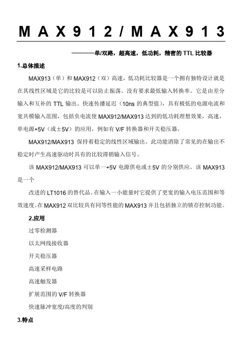
M A X912/M A X913————单/双路,超高速,低功耗,精密的TTL比较器1.总体描述MAX913(单)和MAX912(双)高速,低功耗比较器是一个拥有独特设计就是在其线性区域是它的比较是可以防止振荡。
没有要求最低输入转换率。
它是由差分输入和互补的TTL输出。
快速传播延迟(10ns的典型值),具有极低的电源电流和宽共模输入范围,包括负电流使MAX912/MAX913达到的低功耗理想效果,高速,单电源+5V(或±5V)的应用,例如有V/F转换器和开关稳压器。
MAX912/MAX913保持着稳定的线性区域输出。
此功能消除了常见的在输出不稳定时产生高速驱动时具有的比较滞销输入信号。
该MAX912/MAX913可以单一+5V电源供电或±5V的分别供应。
该MAX913是一个改进的LT1016的替代品。
在输入一小能量时它提供了更宽的输入电压范围和等效速度。
在MAX912双比较具有同等性能的MAX913并且包括独立的锁存控制功能。
2.应用过零检测器以太网线接收器开关稳压器高速采样电路高速触发器扩展范围的V/F转换器快速脉冲宽度/高度的判别3.特点超快速(为10ns)单+5V或±5V的双电源供电输入范围扩展至负电源以下低功耗:6毫安(+5V)的每次比较无最小输入信号摆率的要求无电源电流扣球稳定的线性区可投入任一电源低失调电压:0.8mV4.引脚配置顶视图:5.绝对最大额定值:正电源电压 (7V)负电源电压..............................................-7V差分输入电压.......................................±15V输入电压....................................-0.3V至15V锁存引脚电压...................................等于耗材连续输出电流.....................................±20mA连续功耗(TA=70℃)8引脚塑料DIP(减少9.09mW/妹高于70°)......727mW 8引脚SO(减少5.88mW/每高于70°).................471mW 8引脚CERDIP(减少8.00mW/每高于70°).........640mW 16引脚塑料DIP(减少10.53mW/高于70°).......842mW 16引脚窄的SO(减免8.70mW/高于70°)..........696mW16引脚CERDIP(减免10.00mW/高于70°)..........800mW工作温度范围:MAX91C......................................................0℃至70℃MAX91E....................................................-40℃至85℃MAX91MJ.................................................-55℃至125℃储存温度范围........................................-65°C至150°C焊接温度(10秒).........................................................300℃注:超越“绝对最大额定值“,即可能造成永久性损坏设备。
- 1、下载文档前请自行甄别文档内容的完整性,平台不提供额外的编辑、内容补充、找答案等附加服务。
- 2、"仅部分预览"的文档,不可在线预览部分如存在完整性等问题,可反馈申请退款(可完整预览的文档不适用该条件!)。
- 3、如文档侵犯您的权益,请联系客服反馈,我们会尽快为您处理(人工客服工作时间:9:00-18:30)。
高速比较器
问:为什么我不能使用高增益或开环结构的标准运算放大器作为电压比较器 ? 答:如果可接受的响应时间是几十微秒,可以这样做。
实际上,如果你再要求运算放大器具有低偏置电流、高精度和低失调电压,那么选择运算放大器可能比大多数标准电压比较器更合适。
但是由于大多数运算放大器为了反馈稳定,都具有内部相频补偿,所以使其响应时间达到纳秒级是相当困难的。
然而,低价格通用比较器LM311的响应时间为200 ns。
另外,运算放大器输出与标准逻辑电平不容易匹配。
因为运算放大器没有外部箝位或电平转换电路,它作为比较器工作时输出电压在正、负电源电压范围内有几伏的摆动,所以与标准TTL或CMOS逻辑电平不兼容。
问:我的比较器产生振荡难以控制,为什么出现这种情况?
答:请检查一下电源旁路。
印制线路板上即使几英寸长的电源线导电带都会产生不利的直流电阻和电感。
这样,当输出状态改变时产生的瞬态电流会引起电源电压的波动,通过地线和电源线把这种波动反馈到输入端。
所以在安装低漏电电容(0 1 μF陶瓷电容) 时应尽可能靠近比较器的电源引脚,以便在高速切换期间使电容器作为低阻抗能量储存器。
问:我已经安装了旁路电容器,但是仍然不能解决高速比较器的振荡问题。
现在应该怎么办?
答:可能是比较器的接地问题。
一定要使接地引线尽可能短并且要接到低阻抗接地平面以减小通过引线电感的耦合作用。
尽可能使用接地平面,避免使用插座。
产生振荡的其它原因可能是相对输入端的信号源高阻抗和杂散电容所致。
甚至是几千欧的源阻抗和几皮法的杂散电容都会产生难以控制的振荡。
所以应该缩短引线,包括示波器探头地线夹的引线。
为得到最佳测试结果,应使用最短接地引线(小于2 5 cm)以使引线电感量最小。
问:我缓慢地改变比较器的输入电压,当它通过阈值电压时,我的比较器输出端似乎出现“震颤”。
为什么我从比较器的输出端得不到一个干净的转变波形? 答:比较器的高增益和宽频带通常是这个问题的根源。
噪声不但被放大而且也像信号一样通过转变区,所以噪声快速响应放大器输出,产生来回跳动。
另外,比较器在转变期间其灵敏度(即增益)比较高,由于反馈增加从而引起振荡。
如果有可能,对信号进行滤波以减小伴随的噪声。
为了克服噪声还可以利用滞后特性,类似齿轮系中的间隙,在输出状态翻转之前对输入变化要求有一定的余量。
例如,AD790,输出由高到低转变之后,其内部的滞后特性要求输入电压(正输入)增加500 μV才产生由低到高的转变。
问:如果我的比较器内部不带延迟电路,能否外加?
答:可以。
利用外部正反馈。
这样做使比较器输出端的一小部分送回到正输入端。
这种方法的简单接线如图3 1所示。
从低转变点(LTP)到高转变点(UTP)的延迟后电压取决于反馈电阻 RF,源阻抗RS,输出低电平VL和输出高电平VH。
其中低转变点和高转变点由下式决定:
VL×RSRS+RF 和VH×RSRS+RF
图3 1 比较器外接延迟电路
图3 2示出由于比较器外接延迟电路可以“清理”比较器的输出波形。
图3 2(a)示出的是没有延迟电路的双极性输出的比较器输出波形。
当三角波输入(波形A)通过转变点(地) 时,比较产生强烈振荡(并且把振荡的一部分耦合到地和信号源)。
图3 2(b)示出的是外接5 mV 延迟特性的同一比较器的响应波形,可以看出转变点比图3 2(a)干净得多。
图3 2 延迟电路有助于清理比较器输出波形
外部延迟电路存在的问题是输出电压取决于电源电压和负载。
这说明延迟电压可根据不同的应用而改变。
虽然这会影响分辨率,但这不是主要问题,因为延迟范围一般很小,而且允许有计算值2或3倍(或更多)的安全裕度(safety margin)。
更换几个比较器可有助于相信这种安全裕度。
还应注意,不要使用线绕电阻用于反馈,因为它产生的电感会带来麻烦。
问:传播延迟和传播延迟离差两者之间的差别如何?这两项技术指标哪一个更重要?
答:传播延迟是指从输入信号跨越转变点到比较器输出状态真正翻转所需要的时间。
传播延迟离差是传播延迟的变化作为过激励电平的函数。
如果在自动测试系统中的引脚驱动电路中使用比较器,那么传播延迟离差将决定其最大边缘分辨率(edge resolution)。
相反,可以把传播延迟看作固定的时间偏移,所以可用其它方法进行补偿。
问:我有一个+5 V电源并且不想外加电源。
我能否在单电源情况下使用比较器? 答:可以。
但是为建立一个阈值电压,使用一个在器件共模范围内旁路性能充分稳定的基准源。
该信号幅度也要相对这个基准源。
问:有时会遇到比较器出现意想不到的现象。
产生这个问题的原因是什么? 答:请检查一下输入信号的共模范围。
与运算放大器不同,它的两个输入端的工作电压通常具有相同的水平。
而比较器的两个输入端具有很大的差分电压摆动。
如果两端输入电压超过器件规定的共模范围(甚至在规定的信号范围以内),比较器可能错误响应。
为了使比较器正常工作,一定要保证两端输入信号不超过比较器规定的共模范围。
例如,AD790差分输入信号范围为±VS,但其共模范围为-VS至(+VS-2)。
问:当比较器离线时,为了减小漂移,你能提供一个自动调零电路吗?
答:试验电路如图3 3和3 4所示。
在校准方式时,输入断开,比较器的正输入被切换到接地端。
比较器接入一个带有一对极性相反的低压源的环路,这两个低压源根据该比较器的输出状态交替地对一个缓冲电容器充电。
如果比较器的负输入端高于地电位,那么比较器的输出将为低,1 μF缓冲电容器将被接到负电压源(-365 mV),从而使缓冲放大器输出电压将斜坡式下降直到低于比较器的正输入端(接地)电位为止,即正延迟和偏移,此时比较器翻转。
如果比较器的负输入端低于地电位,那么比较器的输出将为高,缓冲电容器将被接到正电压源(+365 mV),缓冲放大器输出将斜坡式上升。
在最终状态,(当斜坡或变化超过延迟电压时)每次比较器翻转,电流的极性都改变,因此电容器电压平均为缓冲器和比较器的失调电压。
在校准周期结束时,结型场效应管(JFET)输入开关被断开,缓冲电容器充电电压等于比较器和缓冲器的失调电压±延迟电压。
同时,校准信号变低,禁止极性开关的反馈并且使比较器的输入信号接到比较器的输入端(2脚)。
图3 3 比较器输出、缓冲器输出和比较器输入
图3 4 在校准周期期间自动调零比较器总体输出偏移。