约克螺杆机组YEWS操作维护手册
YEWS机组控制系统维修手册

操作指南(基于PLC的控制系统)1.概述1.1 概述约克YEWS水冷螺杆式冷水机组的控制中心是一个基于PLC的控制系统。
它能够控制多个制冷系统(回路),将冷冻水温度维持在设定范围内,并保证冷水机组的安全运行。
该PLC系统监控冷冻水出口温度与设定值的偏差以及该温度的变化速率,以便按要求来启/停、加载/卸载压缩机。
用户通过触模式键盘和液晶显示屏可以看到运行数据和程序数据。
在冷水机组控制中心上有一个主(机组)“ON/OFF”摇臂开关,可用来开启或关闭整台机组,而开启或关闭单个制冷系统则可从相应的液晶显示屏画面中选择。
冷水机组的外部控制接口可以通过Modbus 现场总线获得。
此外,也提供远程遥控接口,以便遥控机组的启/停、限制电流、远程温度重设和报警。
机组参数设置提供密码保护,分别为“观察”、“操作员”、“维修”。
“操作员”:9675;“维修”:1380;返回“观察”级别:1000。
1.2 键盘和显示操作员可以通过键盘从中央位置对整台冷水机组进行控制,获取运行数据、程序设定值和系统命令。
键盘和显示见图1,图2。
1.3 机组启/停开关机组启/停(ON/OFF)开关位于键盘的正下方,如果需要的话,操作员可以用该开关让整台机组停机。
将它置于“ON”的位置,使冷水机组运行。
图1图2显示器为液晶显示器,可用来显示中文或英文信息(每行15个汉字或30个英文字母;共8行)。
该显示屏带有灰度调节、中英文显示切换,均可从相应的显示屏画面中选择。
31:S1;2: 遥控启/停端子;3:S2;4:通讯口1,用于程序升级;5:通讯口2,RS485口可与外部设备通讯,协议为 Modbus RTU ;6: 模拟量输入端子;7:电池;8:滑阀输出;1.4 紧急停机开关(ESD)YEWS冷水机组配有紧急停机装置,一黄底红色开关。
当置于“OFF”(关)位置时,它会切断控制中心内和相应制冷系统的控制电路和电子设备的220V电源。
控制中心内的所有控制电路(包括压缩机)都断电,并且显示也将停止。
约克空调螺杆冷水机组保养手册

约克空调螺杆冷水机组保养手册
保养概述
本手册旨在提供约克空调螺杆冷水机组的保养指南,以确保机组的正常运行和优化性能。
以下是一些重要的保养建议和步骤。
1. 定期清洁
- 定期清洁冷却塔和冷凝器,以确保散热效果良好。
- 清洁过滤器,以保持空气流通畅。
2. 检查冷却液
- 定期检查冷却液的冷却效果和浓缩度。
根据需要进行添加或更换冷却液。
3. 润滑系统
- 定期检查机组的润滑系统,并根据需要添加润滑油。
4. 检查电气系统
- 检查所有电气元件和电线连接,确保安全可靠。
- 定期清洁和检查控制面板。
- 检查机组的电气性能,如电压、电流等。
5. 定期维护
- 保持机组周围环境整洁,避免杂物积聚。
- 定期检查机组的机械部件,如风扇、传动带等。
- 定期检查冷冻剂管路和阀门,确保没有泄漏。
6. 预防措施
- 定期进行机组运行测试,以发现和解决潜在问题。
- 储备常用的零部件,以备紧急更换。
请务必根据实际机组情况,遵循厂家的指导和建议进行保养操作。
此手册仅提供一般性保养建议,具体操作步骤和频率应参考约克机组的用户手册和维护手册。
*注意:保养操作可能涉及到电气和机械部件,建议由专业人员进行。
遵循安全操作规程,确保操作人员的安全。
*
如有任何疑问,请与约克空调螺杆冷水机组的厂家或授权服务中心联系。
他们将能够提供更具体和详细的保养指导。
约克水冷螺杆冷水机组保养手册
约克水冷螺杆冷水机组保养手册◆ 在使用空调之前,请仔细阅读“使用注意事项”。
◆ “使用注意事项”内列举各种与安全有关的重要事项,恳请严加遵守。
1、请不要破坏已包扎好的保温材料,以免在使用过程中,管壁产生冷凝水漏湿吊顶,造成不必要的损失。
2、风机盘管在使用过程中,不要关闭风盘上的阀门,以保障系统正常运行。
3、风机盘管在正常运转时,切勿打开前面板,避免高速运转的离心风轮打伤您。
4、不可将手指或别的东西插入出风口、进风口,以避免受伤害或损坏空调机。
5、不可损坏电源线,不可以拔出或插入电源插头来开关空调器。
6、不要直接用水冲洗空调机,否则易造成触电或其它事故。
7、请不要频繁开关机,空调可能因频繁启动受损。
8、机组长期停用时,盘管及系统内应充满水,以减小管路的腐蚀,但在冬季长期停用时必须把机组及系统内的水全部放尽,以防盘管及供水管路冻裂。
9、在使用控制器面板过程中,不得使用锋利物操作,切勿施加过大的力,以免损坏控制器面板,不得扭曲或拉扯控制器的电线,以免造成控制部件的失灵。
10、务必通过控制器来控制空调机组的运行状态,严禁拔、插电源来进行开关机组。
·在进行机房设备操作前,请仔细阅读本操作规程本工程采用水冷螺杆冷水机组 + 城市热网作为冷热源,夏季冷水机组提供7-12℃冷水,冬季城市热网通过换热器提供50-55℃热水,冷热水共用两台循环水泵。
夏季开启冷水机组、冷热水循环泵、冷却水泵、冷却塔风机运行制冷循环;冬季开启板式换热器、冷热水循环泵运行制热循环。
一夏季制冷循环操作规程:1、冷水机组的开、停机顺序要保证空调主机启动后能正常运行,必须保证:冷凝器散热良好,否则会因冷凝温度及对应的冷凝压力过高,使冷水机组高压保护器件动作而停车,甚至导致故障。
蒸发器中冷水应循环流动,否则会因冷水温度偏低,导致冷水温度保护器件动作而停车,或因蒸发温度及对应的蒸发压力过低,是冷水机组的低压保护器件动作而停车,甚至导致蒸发器中冷水结冰而损坏设备。
螺杆式制冷机组操作维修手册

目录第 1 章使用、操作 11 机组的操作 (1)1-1 首次开机前的准备工作 (1)1-2 首次开机操作 (1)1-3 首次停机操作 (2)1-4 正常开车操作 (2)1-5正常停车操作 (3)1-6 自动停车操作 (3)1-7紧急停车操作 (3)1-8经济器的调试 (3)1-9 运转过程当中注意事项 (4)2 阀门及管路的安全操作 (6)2-1阀门及管路的安全操作注意要点 (6)2-2易产生“液爆”的部位 (6)第 2 章故障分析 61 吸气压力或蒸发压力过低 (6)1-1 蒸发器供液量不足 (7)1-2干式蒸发器管程垫片泄漏 (7)1-3蒸发器内制冷剂侧传热效果差 (7)1-4蒸发器载冷剂侧传热效果差 (7)1-5吸气管路阻力损失过大 (7)2排气压力或冷凝压力过高 (8)2-1冷却水温度高或水量不足 (8)2-2冷凝器水侧结垢 (8)2-3冷凝器内积存制冷剂过多 (8)2-4冷凝器存油量较多 (9)2-5冷凝器内有不凝性气体 (9)2-6空气湿度大 (9)2-7排气管路阻力过大 (9)3 喷油温度过高 (9)3-1冷却水温度高或水量不足 (9)3-2冷凝水侧结垢 (9)3-3冷凝压力(温度)过高 (9)3-4热虹吸油冷却器制冷剂侧存油量较多 (10)3-5喷液量不足 (10)4 压缩机带液运行 (10)4-1氨液分离器或低压循环贮液器液位过高 (10)4-2蒸发器供液量过大 (10)4-3干式蒸发器端盖导程垫片泄漏 (10)4-4蒸发器换热效果变差 (10)4-5吸气管路阻力过大 (11)5油压差过大 (11)5-1油分内油位过低 (11)5-2油路系统或油粗滤网、油精滤芯过堵塞 (11)5-3油温度过高 (11)5-4压缩机内部件磨损,间隙过大 (11)6压缩机耗油量增大 (11)6-1喷油量增大 (11)6-2压缩机吸气带液 (12)6-3排气温度高 (12)6-4排气温度低 (12)6-5油分效果差 (12)6-6三级油分内存油过多或回油不畅 (12)7启动负荷过大、不能启动或启动后立即停车 (12)7-1滑阀未停在零位,带载启动 (12)7-2机体内充满润滑油或大量液体制冷剂 (13)7-3运动部件严重磨损,摩擦力增大 (13)7-4压缩机与电机同轴度偏差过大 (13)7-5电源断器未合上或柜上急停开关未拧开 (13)7-6压差控制器或继电器断开后没有复位 (13)7-7压力控制器或温度传感器调节不当,使触点常开 (13)7-8温度控制器调整不当或有故障 (13)7-9接触器、中间继电器线圈烧毁、触头接触不良或控制电路故障 (13)7-10电机绕组烧毁或断路 (13)8压缩机运行中自动停机 (13)8-1起自动保护作用的继电器或程序动作 (14)8-2电源主回路热继电器保护动作 (14)8-3控制线路松脱 (14)8-4控制元器件故障 (14)9机组振动过大 (14)9-1吸气压力过低 (14)9-2吸入过多制冷剂液体 (14)9-3压缩机与电机同轴度偏差过大 (14)9-4系统管路引起机组振动 (15)9-5机组及主机、电机地角螺栓未紧固 (15)9-6机组安装基础质量差 (15)10压缩机运行时出现异常声音。
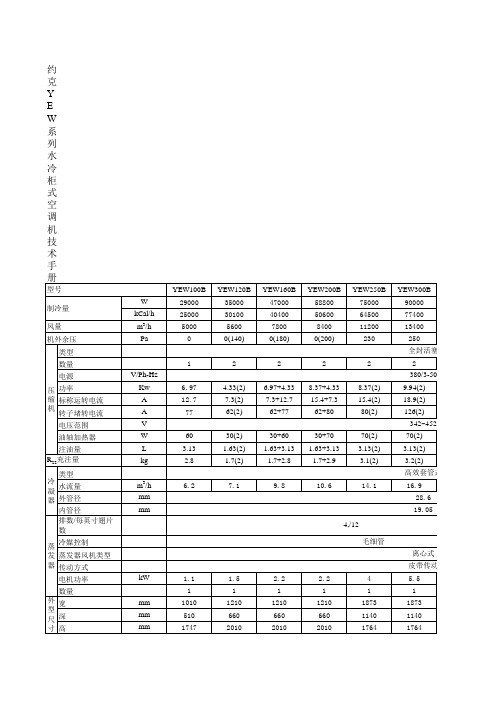
约克YEW系列水冷柜式空调机技术手册
8.37(2)+6.79
12.7+15.4(2)
72+80(2)
342~452
60+70(2)
3.13(3)
2.8+2.9(2) 高效套管式
28.6
20.4
19.05
离心式 皮带传动
5.5 1
1873 1240 1764
YEW400B 120000 103200 16700 250
YEW450B 135000 116100 20000 230
型号yew100byew120byew160byew200byew250byew300byew350byew400byew450byew5200byew610b制冷量290003500047000588007500090000103000120000135000152000180000kcalh25000301004040050600645007740088600103200116100130700154800风量500056007800840011200134001610016700200002520027500014001800200230250250250230330400类型全封活塞数量电源vphhz380350功率kw6974332697433837433837299428372679837399432176175421762标称运转电流1277327312715473154218921271542154318933353963962转子堵转电流776226277628080212627280280312631902152152电压范围342452油轴加热器60302306030707027026070270370310021002注油量313163216331316331331323132313331330313375727572kg2817217281729312322282922933238393982类型高效套管式水流量627198106141169204212253322352mm286mm1905412512冷媒控制毛细管热力膨胀阀蒸发器风机类型离心式传动方式皮带传动电机功率kw11152222555575751111数量mm10101210121012101873187318731873187320732073mm5106606606601140114012401240144014401440mm17472010201020101764176417641764177420182018类型初效可清洗过滤器数量尺寸mm82572096276210309171030917600550600550680550680550680550805620805620净重量kg21032034036061064070073081010301050约克yew系列水冷柜式空调机技术手册注
约克螺杆式冷水机组面板操作说明书

约克螺杆式冷水机组面板操作说明书文章标题:深度解析约克螺杆式冷水机组面板操作说明书序在工业领域中,冷水机组是一种常见的设备,它们在空调系统中起着至关重要的作用。
而约克螺杆式冷水机组作为其中的一种,其面板操作说明书更是每一个使用者必须要了解和掌握的内容。
本文将深入探讨约克螺杆式冷水机组的面板操作说明书,从简单的操作入手,逐步深入,帮助读者更好地理解和掌握这一重要内容。
一、初识约克螺杆式冷水机组约克螺杆式冷水机组是一种高效节能的制冷设备,广泛应用于工业和商业领域。
其面板操作说明书是使用者学习如何正确操作和维护设备的重要指南,不可忽视。
1.1 面板操作说明书的作用约克螺杆式冷水机组面板操作说明书包含了设备的基本参数、运行指示、故障排除等内容,对于使用者而言,它是学习和掌握设备操作的重要参考资料。
通过仔细阅读和理解说明书,用户能够更好地了解设备的工作原理和操作流程,确保设备的正常运行。
1.2 重要性与必要性面板操作说明书是约克螺杆式冷水机组的“使用手册”,其中所包含的内容涵盖了设备的方方面面。
使用者必须深入理解和掌握面板操作说明书中的内容,这不仅可以帮助其更好地操作设备,还能在设备出现故障时快速准确地排除故障,确保设备的安全稳定运行。
二、深入了解面板操作说明书2.1 基本操作流程约克螺杆式冷水机组面板操作说明书首先介绍了设备的基本操作流程,包括开机与关机步骤、调节温度与湿度等功能。
使用者需要仔细阅读并按照操作说明书中的指引来操作设备,确保每一个步骤都得到正确执行。
2.2 运行参数与指示在面板操作说明书中,约克螺杆式冷水机组的各项运行参数和指示都有详细的说明。
使用者需要了解各个参数的含义与作用,并且能够根据指示来进行相应的调整和操作。
2.3 故障排除与维护面板操作说明书还包含了设备常见故障的排除方法和维护建议,这对于保证设备的正常运行至关重要。
使用者应该仔细学习和理解这部分内容,以便在设备出现故障时能够迅速作出正确的反应,保障设备和生产的安全。
约克机组操作与维修保养操作规程
制冷机操作与维修保养规程1.范围本规程规定了YK离心式冷水机组的操作程序及方法。
本规程适用于YK离心式冷水机组机组。
2.操作程序和方法2.1启动程序2.1.1长时间停机后开机2.1.2当系统长时间停机之后, 重新投入运行时, 要把压缩机的润滑油全部换掉。
装上一新的过滤器,并向压缩机注入新油。
在设置界面,让时钟复位。
接通控制中心的115V电路,压缩机油槽加热器要至少加热12个小时。
2.1.3启动油泵(按下并松开油泵手动键),直到建立起稳定的油压为止。
然后再按下并松开油泵手动键。
让油泵停止工作。
若水系统已被排干的话,给冷却水和冷冻水回路加满水。
2.2启动前2.2.1启动冷水机组前,先看控制中心是否显示:系统准备启动。
2.2.2冷水机组启动前应检查:2.2.2.1油加热器---油加热器应提前12小时通电,机组才能开机。
如果油温低于22℃,机组不能开机。
必要时,可以将润滑油放掉,再向油槽添加新的润滑油。
2.2.2.2油泵---检测时,按下控制中心检修键中的油泵手动键,然后松开。
油泵运行10分钟后即停车。
不够10分钟,要让油泵停止运行的话,可现按下并松开油泵手动键。
2.2.2.3在启动冷水机组前,应对控制中心所有设定值编程。
启动之前,要给时钟输入正确的日期和时间。
任何可变的设定值都可以编程。
如果不编程的话,它们的“缺省值”如下:冷冻水出口温度=7.2℃,限流百分比=100%FLA,正常停机阶段的电力需求=无,远程重设温度范围=11℃2.3启动2.3.1启动水泵,保证流经机组的冷冻水流量足够。
2.3.2按下压缩机启动开关,它会自动弹回到运行的位置。
(如果机组已启动过,按压缩机开关的停机/复位侧,然后再按启动侧,即可启动机组。
)当启动开关接通时,控制中心处于运行模式,任何故障都会在显示屏上显示出来。
2.3.3在启动程序的头50秒,微电脑控制中心上将显示:系统预先润滑。
2.3.4油泵将预运行50秒,建立起油压,并给压缩机内所有的轴承、齿轮和旋转面提供足够的润滑。
螺杆冷水机组开机运行维护手册
螺杆冷水机组开机运行手册安全要求只有经过专门培训过的人员可以操作机组(客户可以自行决定是否安装机组操作准入装置)。
请勿覆盖和关闭任何安全装置。
比如水系统和制冷剂系统上的安全阀门。
定期检查安全阀:见“维护安全事项”。
确保有良好的通风,非特别定制产品必须解决防雨、防尘问题。
维护安全事项对机组电气和制冷部件进行操作的工作人员必须经过培训授权认可。
对机组的制冷剂回路进行维护的工作人员必须是经过培训认可的。
所有的焊接工作必须由经过培训认可的专业人员完成。
维护时必须穿戴防护用品(手套,眼镜,工作鞋和防护服)。
定期实行机组的检漏维护,一旦发现漏点,立即修理。
请勿在带电的机组上进行操作。
务必将总电源开关断开,确保机组没电的情况下,才能进行电气元件的维护操作。
注意:即使机组关闭,其电路仍带电,除非机组的主电源开关断开。
具体情况请查阅机组接线图。
贴上合适的安全标贴。
运行检查:在机组的使用过程中,必须按国家相关规定进行检查及测试。
安全装置的检查:每年检查一次机组的安全装置(高压开关)。
每年至少检查安全装置(阀门)一次,如果机组的工作环境腐蚀严重,务必提高机组安全保护装置检查的频率。
禁止试图在机器运作或内部尚有压力的情况下,移除制冷剂回路部件或装置。
确保在移除部件或打开回路之前,压力为OkPa。
因维修需要,打开制冷剂回路时应塞住所有开口。
若回路打开时间超过一天,则需要在回路内充氮气保护。
维修安全措施所有的安装部件必须由专人进行维护,以避免机组的损坏和人员的伤害。
机组一旦发现故障或泄漏必须立即进行维修处理。
由经过授权的技术人员负责及时排除机组的故障。
每次维修以后,必须检查机组的安全装置。
当机组发生泄漏或系统中的制冷剂受到污染,要使用制冷剂回收设备将系统中所有的制冷剂排出并且把制冷剂回收至制冷剂容器中。
充注制冷剂前请确认使用正确制冷剂的型号。
充注别的制冷剂而不是原始型号的制冷剂会削弱机组运行性能甚至可能会导致损坏压缩机。
不允许试图向机组管路通氧气。
约克YS系列螺杆式冷水机组维修技术手册
螺杆压缩机螺杆压缩机
滑阀
转子
吸气
螺杆压缩机螺杆压缩机
打开 滑阀(加载部分负载)
滑阀
转子
吸气
螺杆压缩机
打开 滑阀(加载部分负载)
滑阀
转子
吸气
螺杆压缩机
打开 滑阀(加载部分负载)
滑阀
转子
排气
吸气
螺杆压缩机
滑阀关 (满载)
滑阀
转子
排气
吸气
螺杆压缩机
滑阀关 (满载)
滑阀
转子
排气
吸气
螺杆压缩机
滑阀关 (满载)
轴封包括有一个弹簧承载,十分精密的碳质环,这个一种耐高温有弹性的“0”型静力密 封环,还有一个能减少应力也很精密的搭接型密封套,整个轴封的空穴处于低压状态,来自压 缩机的润滑油经过它流向泄油系统,由于是低压与油直接冷却两者相结合所以轴封寿命长
通过压缩机滑阀的移动使压缩机阴、阳螺杆齿间容积对在齿面接触线从吸入端向排气端移 动的前一段时间内,仍与吸气口相通,并使部份气体回流到吸气腔,即滑阀减少了螺杆的有效 工作长度以达到气量调节的目的。 油分离器:
• 制冷量: • 100-675冷
吨 • 315-2375
千瓦
YS说明
压缩机:壳体采用铸铁经精密加工使转子具有最小间隙,一对用锻钢加工而成采用不对称图形 的螺旋转子相互啮合旋转,造成曲齿型空间组成的容积变化,实现对制冷剂气体的压缩。压缩 机的轴承设计完全能抗磨使能耗减少,可靠增加,四个独立的圆柱形滚柱轴承能承受径向荷载, 两个滚球轴承受轴向荷载,它们的组合能使转子各种压力保持精确定位。
冷凝器
冷凝器也是卧式管壳式结构,有一块排汽挡板能防止高速汽体直接冲刷管束,挡
板也起到良好分配冷媒流量的作用,同样每隔 4 英尺有 1/4″厚的中间支撑板,
约克YS系列螺杆式冷水机组维修技术手册
润滑:
油分离的第一级内及转子轴承处各有一个油槽,保证机组在启动、停机以及电源故障时提供
润滑,机组运行时,依靠压差提供适量油量进行润滑,不需要油泵。
在油分离器油槽内有一只 500W 沉浸式油加热器。一个装在机组外部可更换滤芯,滤孔为 15
滑阀
转子
排气
吸气
电磁阀
出油
“A”加油
“B”
卸载
电磁阀
出油
“A”加油
“B”
加载
滑阀原理
滑阀控制时间
温度、压力传感器的数值在表的范围内显示有效数据,超出后显示 “XXXX”
控制面板
主界面
系统界面
蒸发器界面
冷凝器界面
压缩机界面
滑阀控制界面
油分离器界面
机电启动界面
固态启动器界面(B型)
冷凝器
冷凝器也是卧式管壳式结构,有一块排汽挡板能防止高速汽体直接冲刷管束,挡
板也起到良好分配冷媒流量的作用,同样每隔 4 英尺有 1/4″厚的中间支撑板,
冷凝器底部有冷媒液体过冷器。
螺杆机外形结构
主要组成部分 1/ 蒸发器 2/冷凝器 3/压缩机 4/节流装置 5/驱动电机 6/控制中心 7/启动控制器
设定值界面
设定值界面
设置界面
历史记录界面
设置界面
机组启动顺序
面板按启动后,需要经过:水流开关检查-传感器自动对零-在30 秒启动压缩机
保 护 参 数
YS机组正常停机和安全保护性停机
• 周期运行性停机-自动启动 1/冷冻水温度过低 2/水流开关断开 3/防止重复启动 4/电源故障 5/交流电压过低 6/线电压过低 7/线电压过高 8/马达控制外部重置 9/机组周期运行 不需要手动复位,在周期性工况不
- 1、下载文档前请自行甄别文档内容的完整性,平台不提供额外的编辑、内容补充、找答案等附加服务。
- 2、"仅部分预览"的文档,不可在线预览部分如存在完整性等问题,可反馈申请退款(可完整预览的文档不适用该条件!)。
- 3、如文档侵犯您的权益,请联系客服反馈,我们会尽快为您处理(人工客服工作时间:9:00-18:30)。
YEWS100SA50D / YEWS170SA50D / YEWS210SA50DSTYLE DWarningRefrigerant with certain pressure is infused into this systemIt is possible to damage the system severely if be with the incorrect operating procedure when in maintaining. All the maintenances should be performed by the maintenance technician of YORK in accordance with the Installation, Operation and Maintenance Manual of YORK.IMPORTANT !Please read carefully before proceeding!General Safety GuidelinesThis equipment is complex, when performing the installation, operation and maintenance, the personnel may be exposed to the following circumstances or dangers caused by components, including but not limited to: refrigerants, engine oil, compressive material, rotation part and high-low voltage, which will result in personal injury or even casualty if in improper handling. The operation/maintenance personnel have the responsibility to confirm these potential dangers to protect him from the injury while work safely. If these safety requirements are not followed, serve damages on the equipment and property will be caused, or even casualty on the personnel concerned.This manual is just for the authorized operation/maintenance personnel, whom are professionally trained to handle the appointed work safely and correctly. Most important of all, please carefully read and master this manual and other references before any operation on this equipment. The operator is required to be familiar with and follow any relevant government standards and criterion.Variability of this DocumentYork inherits the strategy of updating the product continuously, so that the information in this document can be correspondingly updated without prior notice. York is in no promise to provide the latest information to all the owners of this manual; however, the user can acquire these information from the nearest representative office of engineering system service of York.It is the obligation of operation/maintenance personnel to determine the applicability of the corresponding equipment. If any question before operation, they will contact the customer to confirm whether the equipment have been updated and whether there is the latest available document or not.NomenclatureA50Y E WS100S DStylePower supplyRefrigerant A-R134aS-Standard unit100-Unit modelWater cooled screw chillerHigh efficiencyYORKSection 1 Supplier Information Section 2 Product IntroductionSection 3 Transportation, Transferring and Storage Section 4 Installation Section 5 Control Center Section 6 Startup Commissioning Section 7 Operation Section 8 Maintenance Section 9 Trouble Shooting Section 10 Technical Data Section 11 Spare PartsSection 12 Transferring Stop, Removal and HandlingSection 13 Installation Instructions for the HF68 Flow SwitchesTable of Contents149111742448535561626341.1 IntroductionYork YEWS-D water chiller complies with the most rigorous design and manufacture standards, which ensures the high-quality, reliability and flexibility of various air-condition project.This unit can be used for supplying the chilled water, however, be unsuitable for other applications beyond this manual.This manual contains all the necessary information of operation and maintenance guide for correct installation and testing.Please read this manual carefully before operating and overhauling the unit.All the work elaborated in this manual (including installation, testing and maintenance) should be performed by the trained professional personnel.The manufacturer should not burden any responsibility of injury or damage due to improper installation, testing, operation or improper maintenance, or disobeying the process and guidance in this manual.1.2 WarrantyOne year upon the date of startup and commissioning, or 18 months upon the date of shipment (subject to the prior arrival), Y ork guarantees to remedy the defect of the manufacturing process and material of all the equipment and parts, excepted as the guarantee period is extended in the Contract.The warranty is limited to alter and transport any faulty parts or components, if this part is unavailable due to quality or manufacture problem, the compensation must be supported by the evidence, namely the fault occurs in the guarantee period and the unit is run in the specified parameters.Section 1 Supplier InformationAll the compensation for the warranty must show the unit model, series no. and order no., all of which are printed on the tablet of the unit.Before getting the written consent of YORK International Inc., any alteration on the unit shall be prohibited, or the warranty should be invalid.The following clauses should be obeyed to comply with the product warranty: the commissioning of startup should be performed by the authorized personnel of Y ork. Only the parts, lubricant and refrigerant recognized by York can be adopted.In the regulated time, all the operation and maintenance required in this manual should be completed by the eligible trained personnel. The warranty should lost efficacy automatically for disobeying any above-mentioned clause.1.3 SafetyThe safety standards of YEWS-D water-chilling unit designed and manufactured by the factory passed the attestation of ISO 9000, which meet the limitation regulated in this manual and comply with the following standards: JB8654 Safety Requirements of Positive Displacement and Centrifugal Water-chilling (Heat Pump) Packages.1.4 Safety LiabilityWe take the safety liability into account in designing and manufacturing the unit to ensure that it can meet the safety requirements. However, the followings must be placed in the first in operating any equipment: personal safety, other personnel and equipment safety . Please operate this machine correctly according to the processes in this manual.1.5 About This ManualThe following words in this manual are used for1reminding the operating personnel to pay attention to the potential dangers.The WARNING in this manual is used formarking the dangers that may cause thepersonnel accident. The guidance, simpleexplanations and possible aftermath due toneglecting these guidance should generally begiven, which are expressed in black on redlabel.CAUTION signs the dangers that may result inthe damage of machine, destroy of otherequipment, or environment pollution. Theguidance, simple explanations and possibleaftermath due to neglecting these guidanceshould generally be given, which are expressedin black on yellow label.NOTE is used for highlighting the other usefulinformation, which has no special relation withthe safety, and they are expressed in black onwhite label.The contents of this manual contains the optimal operational approach and process recommended by Y ork, however, it is just for guiding, but not overriding the above-mentioned personal responsibility and local safety ordinance.The copyright of this manual and other information presented together with the product will be in the possession of Y ork. The whole or part of them can not be translated without the written consent of representative of York.1.6 Used EquipmentApplicabilityThis unit can be used for supplying the chilled water, however, unsuitable for other applications beyond this manual. It is possible to cause personnel injury or equipment damage if used for other purposes or in misoperation. The design limit appointed in this manual can not be exceeded in the operation.Supporting structureThe solid supporting structure is required to supply for the unit to avoid the personnel injury or equipment damage.Mechanical strengthThe unit shall not burden load or pressure from the neighboring equipment, pipe or structure. The other parts are forbidden installing on the unit, for any external load or pressure may destroy the structure to further injury the operator or damage the machine.General usageThe appropriate safety precautions should be adopted when operating the unit, or some dangers will happen easily and result in the injury. (Make sure that the password of the unit is just mastered by the authorized person, who knows the possible dangers and necessary safety precautions in the operation and maintenance process, and how to maintain the hot temperature, high voltage and electrical equipment much well, which is very important).Pressure systemThe unit contains the refrigerant vapor and liquid with certain pressure, so that the leakage may result in dangers or cause the injury in the running or unused. The user should ensure that the installation, operation and maintenance are very careful to avoid damaging the pressure system. Please do not attempt to close the spare parts of the pressure system except the professional personnel.Electrical SystemThe unit must be earthed; therefore, the installation or maintenance is forbidden before shutting off the main switch, insulating the power of unit and any controlling power, all of which are completed via the special tools by the trained personnel. Please do not attempt to touch the inside of operation board, distribution board or otherCAUTION NOTEWARNING 2electrical cabinet.Refrigerant and lubricantThe refrigerant and lubricant used by the unit are generally non-toxic, nonflammable and no corrosive, which can not cause particular harm to the body, however, the gloves and safety goggles had better to be put on when in working. Taking leakage as an example, the people will suffocate in the limited or closed space, so that please pay attention to keeping good ventilation in the machinery room.Cleaning under high temperature and high pressureDo not clean any parts of pressure system under high temperature and high pressure (such as swash with the vapor), for which may result in pressure relief. The detergent and solution are also forbidden to avoid the corrosion.1.7 Emergency stopOne switch of emergency stop is set on the electrical control cabinet, which is the red button. When the emergency happens, this switch can cut off the power of the controlling system, as well as lock the switch on the place of OFF.1.8 Safety SignsThe following signs are stuck on each unit to show the guidance or the potential danger. The meaning of each sign is as follows:In white on blue. Please read the instructionfirstly to be convenient for operation.In black on yellow. W arning-hot surfaceIn black on yellow. W arning-please cut off allthe powers before dismantling/removing thecover otherwise the fatal danger will happen.In black on yellow, sign for general attention.32.1 IntroductionYork YEWS-D water-chilling unit is used for supplying the chilled water; all the units are designed to be installed in the room (machinery room).2.2 CompressorThe semi-hermetic twin-screw compressor is adopted to ensure the high-efficient and reliable operation. The capacity control can be realized via the slide valve. The compressor is positive displacement with two spiral steel rotors. The motor with 50HZ can drive the male rotor directly with the rotational speed of 2975rpm, while the male rotor drives the female rotor, one flat of slim oil film is between the female and male rotor.Each compressor is direct-driven and semi-closed twin-screw, and including the followings: twin-screw rotor made from the forged steel, while the unit of precision machining compressor is made from the cast iron. The high-efficient oil separator is placed inside the machine.The inner discharge check valve can prevent the rotor from reversing when the machine stops.The high-efficient semi-closed electrical machinery can cool the suction, which also is with the overload protection, thermoelectricity resistance and over-current protection.The suction filter and full-flow oil filter are installed inside the compressor.The refrigerant gas is sucked into the interspaces constituted between the 5 gear male rotors and 7 gear female rotors, and then the rotor further meshes to close the rotor spiral in the suction mouth and unmeshed the compressed gas in the discharge mouth along with the axis direction. Before the designed capacity leaves the rotor exhaust chamber, the steam capacity is compressed,Section 2 Product Introductionwhile the pressure increases. Because the cycle of the suction and discharge is superposed, the airflow can keep stable.The rotor is inside the body of the compressor, while the body is made from the cast iron with precision machining to minimize the interspaces between the shell and rotor. The contact between the male and female rotor is mainly on pitch circle of each rotor, so that the rotor can not be abraded much and the reliability can also be increased. The compressor adopts the wearable bearing to decrease the power waste and strengthen the reliability, while four single cylindrical roller bearings burden the radial load; the angular contact ball bearing burdens the axial load. No matter under any pressure ratio, they can keep the correct orientation of the rotor, which can reduce the leakage and keep the efficiency. One check valve is set in the discharge port, which can be used for preventing the rotor from reversing due to the pressure grads of refrigerant when the unit is stopped.The refrigerant vapor from the evaporator flows with the motor and cools it. The overloading protection includes the over heating protection and over-current protection.The inner oil separator separates the oil from the refrigerant to directly turn back the compressor to lubricate.One inserted heater of 350W is set in the compressor, which is in constant temperature control; therefore, it can prevent the refrigerant from dissolving into the lubricant. Motor startupThe compressor motor adopts the star-shaped/triangle conversion starter, which includes 3 motor contactors and 1 startup relay and can restrict the startup electrical current in 33LRA around in the first 4~10 seconds, after completing the connection of the triangle, the electric current raise to the normal level.4The corresponding relay is electrified when the microprocessor gives out the compressor startup signal. The relay contacts switch to startup and connect the motor starter in the situation of start-shaped and keep 410 seconds.Capacity controlThe compressor should be started up in the minimal loading place, and reach the capacity control in full loading of 25100 via one continuous slide valve.The spring of the capacity adjustment is automatically reset the minimal loading place to ensure the startup of the compressor motor in the minimal loading.2.3 Oil SeparatorThe inside separator separates the majority of the oil and lubricate it directly, while a few of oil is separated to turn back the compressor.The oil can only return the compressor by one oil filter with one removable filter cartridge; the oil is in high pressure, which leads back the oil to compressor to lubricate the bearing and rotor.After that the oil is sprayed to the closed spiral near the suction rotor. The oil spraying is finished automatically due to the differential pressure between the discharge pressure and suction end, which not only lubricates the rotor and used as oil seal, but also reduce the leakage to ensure the compression of the refrigerant (capacity efficiency).When the compressor is running, the oil level must be higher than the visible location of the sight glass, please stop to check the reason once lower than and to inject the oil according to the actual situation, while the oil level can not be higher than the upper sight glass of inner oil separator, please stop to check and determine whether the oil should be discharged or not according to the actual situation once higher.2.4 Circuit of Refrigerant Each unit is with one independent refrigerating circuit, the liquid pipe includes: manual globe valve with infusing nozzle, throttling device and air bypass electromagnetic valve.2.5 CondenserThe condenser is the shell and tube type, which can be washed. The heat exchanging pipe is the 19mm seamless copper tube with outer finned and expansion joints to the tube plate, with one super cooler in the inner.The designed pressure of the water is 10bar. HG20615 flange is set on the water pipe joint to be convenient for connecting with the pipe. The designed pressure of the safety valve of refrigerant is 20. 7 bar, and the condenser is manufactured and inspected in accordance with the State Standards of China GB 151.2.6 EvaporatorThe flooded evaporator is adopted with the water inputs and outputs from the same side. The designed pressure of the safety valve of refrigerant is 20. 7 bar, and the condenser is manufactured and inspected in accordance with the State Standards of China GB 151.The shell is wrapped with the soft aperture-closed heat preservation material in the thickness of 19mm. HG20615 flange is set on the water pipe joint to be convenient for connecting with the pipe.2.7 Distribution Board and Control PanelAll the control and startup components for the unit are wired and completed the performances testing by the factory. The cabinet is designed according to IP23 and manufactured with the steel plate of powder spraying.The distribution board and control panel is divided into the power, control and startup cabinet according to the electrical system. The power and control part are with the individual hinged door, and each door has the lock and sealing pad.Each distribution board includes: compressor startup5contactor, control circuit, compressor contactor coil and components of compressor overloading protection.The overload protection of compressor is running as follows: read the electrical current signal to the control mainboard via CT, and to protect once exceeding the setting value upon comparing with FLA value.The power protection module of compressor provides the protection hyperlow / hyperhigh / phase sequence/phase out of input voltage.The control panel contains: microcomputer keyboard, HMI and microprocessor panel.2.8 Microprocessor ControlThe microprocessor is with the following performances and displays: liquid crystal display with 120 characters, which can display text with 8 lines of Chinese character and English letters or digit code, back lighting with the LED to be convenient for reading. Sealing keyboard with 20 keys, which are divided into function keys and programme keys.The standard controller includes: running signal contact, unit alarming contact, refrigerating pump and cooling pump control, automatic reset after break, system automatically optimization according to the running situation.The software is memorized in the flash memorizer to avoid the faults of the water chilling unit due to breaking of alternating current power. The program set values is saved in EPROM memorizer. The timing clock of controlling system is provided by RTC, and the service life of the backup lithium battery is 5 years at least.2.9 Current protection of motorThe motor protection of microprocessor provides the overcurrent protection to ensure that the motor is free from the damages due to excessive voltage and refrigerant and other overcurrent problems.After 3 seconds upon starting the star-shape/triangle starter, if the current exceeds 115FLA trip point, the microprocessor will stop the system and lock to be the fault. It is required to reset the corresponding system switch to eliminate the fault and restart the system. Please check the motor, circuit and refrigerating system before restarting.With measuring that the current is lower than 10 FLA(full loading), the microprocessor will also provide the under-current protection. The microprocessor will stop the running once under-current. The under-current protection will perform after 4 minutes of triangle starter startup to ensure that the system keeps running under the situations of without refrigerant, connecting of the motor protection components and mechanical high-voltage switch. It is required to reset the system switch once tripping due to under-current.Components of motor protectionThe electronic motor protection components provide the overheating protection, resistance of three phases PTC (Positive Temperature Coefficient) is installed in each phase of motor winding for protection. The resistance value of sensor will keep in 1K within 125. It will trip once coming up to 13K, so that the control circuit is in no electricity. When the motor cools down and the resistance of sensor reduces to 3.25K, the unit can be restarted again.The signal will be output to the mainboard to stop the motor once the protection components trips.2.10 Keyboard ControlDisplayThe parameters can be displayed in Chinese and English, and the following parameters for each circuit will be displayed:Input/output temperature of chilled waterInput/output temperature of cooling waterTime and date, start and stop time at ordinary days, arrangement on holidays and status of access beyond in manual.Compressor running time and startup times Compressor running status6Suction, discharge, oil pressure and discharge temper-ature of the systemPercentage of compressor current in full loading current Cutoff value and setting value: output temperature of chilled water, hyperlow of the suction, overhigh of the discharge and temperature, overhigh current or hyperlow, hyperlow of the chilled waterSetting value of unloading limit for overhigh discharge pressure and compressor currentInformation for exceeding the running limitFaults stop records over 50 timesInputSetting the output temperature and temperature difference of chilled waterClockSetting the time, startup and stop schedule for ordinary days or holidaysProgrammingSetting with the signals from YORK ISN or building automation system: hyperlow breaking value for output temperature of chilled water, restart timer for 180300 seconds, unloading point for average current, reset the setting value for output temperature of chilled water.Additional functions (with password) to be convenient for the professional inspection and maintenance technician to programme.Cutoff value: hyperlow suction pressure, overhigh discharge pressure, overhigh discharge temperature, unloading setting value for overhigh discharge pressure, percentage limit of compressor current.2.11 Accessory and SelectionWith the standard RS485 joint, YORK ISN building automation system can directly provide the commun-ication signal to the standard control panel.Flow switchGate flow switch, the designed working pressure is 10.3bar and applies for the chilled water and cooling the water pipelines.25mm spring shock absorberThe horizontal adjustable spring shock absorber is installed below the ground plate of the unit (on-site installation).2.12 Performance DescriptionLow pressure refrigerant liquid absorbs the hot outside the pipe in the flooded evaporator and evaporate as the refrigerant vapor, after that the low-pressure vapor enters into the compressor, while in the compressor, the pressure and temperature raise as the high temperature and high pressure gas, which separate the mixed lubricant in the outer and inner oil separator, then the lubricant returns back to the compressor for cycling. The oil-free cooling steam in high pressure and high temperature enter into the condenser, while the cooling water absorbs the heat of condensation, the refrigerating vapor cools to be the over-cooling liquid, and then the refrigerant liquid enters into the throttling device and decrease the pressure and temperature to reach the evaporator, then the whole refrigerating cycle is finished.7F i g 2-1 F l o w C h a r tSection 3 Transportation, Transferring and Storage3.1 Delivery and StorageIn order to acquire the stable quality and utmost reliabil-ity, all units have been tested and inspected before leaving the factory. The complete unit is shipped, moreover, the refrigerant YORK L oil with certain pressure is injected. The unit can not be shipped with the export crate, excepted as otherwise are especially marked in the sales order.If the unit needs to be stored before installation, please adopt the followings precautions:Make sure that the unit is free from wind and rain.Make sure that all the opens (such as pipe joint) are with the protective cover or blanking plate.The unit should be stored in the place without many persons to reduce the dangers of accidental mechanical contusion.Don't wash with the steam to avoid operation of relief valve.Please remove the key to the control panel and hand over to the principal. Please inspect the unit periodically in the period of storage.3.2 InspectionPlease remove the transportation package to inspect the unit and confirm that all the parts have been received and without any damage due to transportation. Any obvious broken must be remarked on the waybill of the forwarder, and claim for compensation according to the guidance on the notice.3.3 TransferringBefore transferring the unit, please confirm that the applicable installed device and tools in the installing location, and which can burden the weight of the unit and all accessories.The unit is designed to hoist with the wire rope, one beam showed in the following picture hoist the unit (hoisting hole on tube plate can adopt 6.8shackle), the hoisting component must be long enough for avoiding all the hoisting, also the damages caused by the hoisting chain. The hoisting component must reach the requirement of the unit weight.Do not move the unit on the roller, or hoist theunit by the fork-lift truck.CAUTIONFig 3-1 RiggingThe field for installing the unit must be the floor, mounting pad or foundation, of which the horizontality must be within 6mm and can burden the operation weight of the whole unit.The unit must be placed in the machinery room with the temperature of 4.443.3¡æ, there is enough space around and above the unit for the routine maintenance. The space for cleaning the evaporator and condenser should be retained at one end of the unit, as well as make use of the door opening or other suitable opening. Space for maintenance requirement The space requirement is as follows:Back, side and upper part of the unit-610mm Front of the unit-914 mmPipe removal-See the below table:4.3 Installation of Shock AbsorberThe selected shock absorber can be bulk transported along with the machine.Place the correct installation location upon the Foundation drawing (Refer to Section 10).Fixation-InstallationTwo methods for selection: rubber shock pad, spring shock absorberRubber shock pad: place each pad on its correct location respectively, and then set down the unit carefully on the shock absorber.Spring shock absorber: place each pad on its correct location respectively, and then set down the unit carefully on the shock absorber.Equally distribute the weight of unit on the spring via regulating the adjusting nut on the spring shock absorberSection 4 Installation4.1 SummaryThis manual introduces how to install YEWS-D screw water cooled chiller. The standard unit for usage is generally installed well, and the pipes and circuits are prepared well, and the nitrogen or refrigerants has been infused. When it is installed on the site, it just requires completing the connections of chilled water pipelines, water pipe of condenser, safety pipelines of refrigerant gases and power, etc.The business representative of Y ork will provide the services of installation inspection and initial startup in accordance with the requirements in the contract. If the followings are not obeyed, Y ork shall keep the right to stop the liabilities of Three Guarantees:1. Prohibit to opening any valve or connector under any circumstances, for which will result in the leakage of the nitrogen or refrigerants.2. Excepted that the business representative supervises of York, otherwise no removal or startup of the unit upon any reason.3. No final power connection for the compressor motor or the controlling center.4. No oil injection in the system.5. Do not attempt to startup the system.6. Please do not infuse the hot water or steam (the highest temperature is100F ¡ã, 38¡æ)into the evaporator once the chiller is powered on.4.2 Arrangement RequirementsThe YEWS-D unit is generally located in any plane inside the building because of its low noise and slight vibration the structure of the plane is just required to support the operation weight of the whole unit.In order to reduce the influence on the surroundings from the vibration and noise, it suggests that the unit should be installed in the area, where the vibration and noise is insensitive.ModelSpace for removing the pipe YEWS100SA50D2100mm YEWS130SA50D /170/2102650mm。