Congestion Propagation among Routers in the Internet
Correspondence Information
Architecture and Analysis for providing Virtual Private Networks(VPN) with QoS over Optical WDM NetworksY ang QinSchool of Electrical and Electronic EngineeringNanyang Technological UniversitySingapore,639789Krishna SivalingamSchool of Electrical Engineering and Computer ScienceWashington State University,Pullman,W A99164,USABo LiDepartment of Computer ScienceHong Kong University of Science and TechnologyClear Water Bay,Kowloon,Hong KongCorrespondence InformationProf.Krishna SivalingamBoeing Associate Professor of Computer ScienceSchool of Elect.Engg.&Computer Science102EME BuildingWashington State UniversityPullman,WA99164-2752Phone:5093353220Fax:253-295-9458(Please email to addr below after sending Fax)Email:krishna@AbstractIn this paper,we study the problem of employing virtual private networks(VPN)over wavelength division multiplexing(WDM)networks to satisfy diverse quality of service(QoS)requirements of dif-ferent VPNs.A wavelength routed backbone network is considered.A VPN is specified by the desiredlogical topology and an a priori traffic matrix.The network provides three type of paths over whichsessions are established:(i)Dedicated lightpath(DLP)–an all-optical path spanning intermediate opti-cal cross connects,which is used by exactly one VPN;(ii)Shared lightpath(SLP)–an all-optical pathshared by multiple VPNs.Access nodes(where E/O conversion takes place)at the border of the opticalbackbone provide the necessary electronic buffering when contention arises due to shared lightpaths;and(iii)Multi-hop path(MHP)–a hybrid path composed of a tandem of optical lightpaths with O/E and E/Oconversion at the junction between the two lightpaths.Depending on the QoS requirements of the VPN,one or more of these lightpath types are used to carry the VPN’s traffic.Three traffic types are defined–Type1carried over DLPs as far as possible;Type2carried over SLPs;and Type3carried over MHPs.AVPN’s traffic matrix will specify information on each of the three different types.The network will thentry to accommodate the given requirements,maximizing the the network utilization.In this paper,wepresent a simulation based analysis of the system performance for different system configurations,e.g.different number of wavelengths on physical links,different number of VPNs that share one lightpath,etc.Keywords:Optical WDM Networks,Virtual Private Networks,Wavelength Routed Networks,Quality of Service.1IntroductionA Virtual Private Network(VPN)may be defined as an overlay network that is built over a public network infrastructure,providing the VPN user with a private network using tunneling,encryption and authentication mechanisms[1].VPNs are gaining an increased acceptance due to the economic benefits.VPNs may bebuilt above different types of public networks,such as Frame Relay,ATM or the Internet.The primary advantages of VPNs over Internet are their cost-effectiveness andflexibility.However,the disadvantages of VPNs over Internet are the lack of reliability and sufficient Quality of Service(QoS)mechanisms.Optical wavelength division multiplexing(WDM)technology,that provides substantial bandwidth ca-pacity,is becoming a practical reality with recent technological advances[2].Such networks are expected to play an important role in the future wide area networks(WANs).There is a large number of research ideas on supporting“data directly over optics”on WDM networks.This has been fueled by the promise that the elimination of unnecessary network layers will lead to a vast reduction in the cost and complexity of the network[3].In this paper,we explore how VPNs can be supported in optical WDM networks,in particular WDM mesh routed networks.The WDM routed network provides an“optical connection”layer which consists of several lightpaths.A lightpath is defined as an all-optical connection from the source node to the destination node,traversing several intermediate optical wavelength routing(or cross-connect)nodes.The optical core is composed of these wavelength router nodes which may possess a limited degree of wavelength conversion capability.Access nodes exist at the boundary of the backbone network and provide the interface between the electronic data equipment and the optical core.The access nodes perform E/O conversion when data enters the core,and O/E conversion when data leaves the core.The network architecture considered is as follows:A network provider owns an optical WDM backbone network and provides capacity to users(rge corporations)requiring VPN services.A VPN is specified by a set of nodes that need to be interconnected and a priori traffic demands for the VPN.This is similar to the virtual topology concept that has been studied earlier[4].The difference in this work is that we consider a set of logical topology specifications,and the different types of lightpaths described later.The network provider’s objective is to maximize the total amount of VPN traffic,meet the QoS specifications and optimally utilize the backbone capacity.The proposed architecture separates different VPNs in the opticaldomain by providing lightpaths with different transmission qualities to meet the QoS requirements of the different VPNs.The network provides three type of paths over which the VPN traffic is carried:(i)Dedicated lightpath (DLP)–an all-optical path spanning intermediate optical cross connects,which is used by exactly one VPN. The delay incurred by VPN traffic is due to propagation delay,wavelength conversion delay,and O/E and E/O conversions at the access nodes.(ii)Shared lightpath(SLP)–an all-optical path shared by multiple VPNs.Access nodes(where E/O conversion takes place)at the border of the optical backbone provide the necessary electronic buffering when contention arises for a lightpath.Here,once data enters the core,the only delays are due to propagation and wavelength conversion.However,there is the additional queuing delay at the access nodes;and(iii)Multi-hop path(MHP)–a hybrid path composed of a tandem of optical lightpaths with O/E and E/O conversion at the junction between two lightpaths.Here,additional delays can take place at the light-path junctions if queuing is necessary.This type of path is similar to the classic IP path where queuing is done at intermediate IP routers.Depending on the QoS requirements of the VPN,one or more of these lightpath types are used to carry the VPN’s traffic.Type1traffic is carried over a DLP as far as possible,then Type2traffic is carried over a SLP as far as possible;andfinally Type3traffic is carried over a MHP.Given a set of different VPNs and their specification,the networkfirst attempts to meet the demands of Type1traffic using DLPs,Type2traffic using SLPs,and Type3using MHPs.When dedicated LPs are no longer available,it establishes shared LPs where the number of VPNs sharing a lightpath is limited based on certain performance specifications.When shared LPs are not feasible,multi-hop paths are set up.We conduct simulations to investigate the performance of the network in terms of average packet delay. System parameters that are varied include the number of VPNs,number of wavelengths,and the traffic patterns.The rest of the paper is organized as follows.In Section2,a brief background on VPNs is provided.In Section3,the proposed framework for supporting VPN over WDM networks is presented.Preliminary results from simulation analysis are discussed in Section4.A summary and description of ongoing research is provided in Section5.2BackgroundA virtual private network uses a public network’s infrastructure to make the connections among geographi-cally dispersed nodes,instead of using cables owned or leased exclusively for one single network’s use,as is typical for a wide area network(WAN).To the user,a VPN looks like a private network,even though it shares the network with other users.There are several uses for a VPN.It can be an extended intranet, connecting geographically distant facilities into a cohesive network.It can also be an extranet,linking cus-tomers and suppliers for increased efficiency.Although,there are several type of public networks that can be employed to create a VPN,the most popular and prominent VPNs are based on the Internet.The primary advantages of VPNs over Internet are cost-efficiency,flexibility and scalability[1].The chief mechanisms that enable VPN provisioning are tunneling and security.With tunneling,each packet is encapsulated by a new envelope or capsule that carries the addresses of the source and destination VPN servers.In this encapsulation process,the VPN software appends a new header,which contains a new source and destination address to the packet before sending it out on the Internet.Security is provided by encryption,authentication and other mechanisms.Although providing VPN is cost-effective andflexible,there are a few problems.Quality of service (QoS)is difficult to guarantee when traffic is encrypted because the bits marking QoS cannot be read by the routers.Tunneling protocol cannot guarantee the minimum delay due to IP’s best effort packet forwarding. The current VPNs over Internet are limited to handling low-priority enterprise traffic.With with rapid emergence of e-commerce and VPNs,reliability and security are becoming a great challenge for Internet-based VPNs.With various enterprises turning to VPNs,providing diverse QoS becomes another important issue since different applications have different size and delay sensitivities.These requirements would accelerate the development of new technologies for the next generation VPNs.The next section examines how optical WDM networks can be used to support VPNs.3Proposed Architecture for VPN over WDMIn the context of future optical networks,providing QoS is one of the critical research issues.Traditional optical networks such as synchronous optical networks/synchronous digital hierarchy(SONET/SDH)have been perceived as high transmission rate networks without provision for any QoS to different trafficflows. Recently,some attention has been given to coarse-grain QoS using differentiated optical services[5].By applying the virtual private network concept to WDM,we explore how QoS may be provided.3.1Basic FrameworkIn this section,we discuss the framework for employing virtual private networks over WDM as illustrated in Fig.1.The wide area network connectivity is provided by a wavelength routed backbone network.The optical network consists of several switch nodes interconnected by multi-wavelength WDM links.The access nodes provide the electronic interface to end users,which may be regional networks that feed into the optical core network.The basic idea of this work involves segregating different VPN traffic types in the wavelength domain to provide support for tunneling and QoS.The goal is to establish several VPNs on the physical topology,where each VPN is specified by a set of constituent nodes that comprise it,and the long term average traffic demands.In addition,different VPNs may have different QoS requirements such as bounded delay,guaranteed bandwidth,etc.Thus,each VPN can be viewed as a logical or virtual topology that is embedded on the physical topology[4].For example,VPN1is specified by a topology that consists of the three access nodes,A,C and D.Forthis VPN,lightpaths will be established in the optical network between the pairs. We assume that the wavelength converter is not available in all the switch nodes in this paper.The lightpath for(A,C)is given by;for(C,D)given by;and for(A,D)given by.Thus, all of VPN1’s traffic will be carried by these lightpaths.For VPN2,only two nodes,(A,C)are specified and the lightpath assigned is.Given the above framework,we formulate the problem as follows.The inputs are the physical topology of wavelength routed networks,number of wavelengths on each physical link,number of transmitters and receivers on each switch node,a set of VPNs with their topologies,traffic demands and QoS requirements. The objective function is to maximize the amount of traffic carried by the VPNs,subject to the physical constraints and QoS requirements.3.2Different types of LightpathsThe wavelength routed network provides the following three different lightpath types:Dedicated Lightpath(DLP):is an all-optical path where the traffic is carried entirely in the optical domain within the backbone.The path is composed of links spanning intermediate optical routers with a trans-mission wavelength specified for each link.It is dedicated since it is allocated to carry exactly one VPN’s traffic.This is the most expensive lightpath type,and its utilization will depend entirely upon the alloted VPN’s traffic.The delay experienced by the VPN along this path will be the end-to-end propagation delay and wavelength conversion delay.Therefore,this lightpath can be alloted to VPN traffic that demands the highest level of QoS in terms of bandwidth or delay.Shared Lightpath(SLP):is also an all-optical path,but it is shared among multiple VPNs.The maximum number of shared VPNs and the sharing mechanism is determined by the various QoS requirements.When a SLP is currently used by a VPN,traffic from another shared VPN that arrives at the access node is elec-tronically buffered and transmitted after the considered VPN completes the transmission.When severalcompeting VPN traffic arrive during a busy period,an appropriate scheduling algorithm has to be used.This type of service is less expensive than the DLP,but the lightpath utilization is higher due to traffic contribu-tion from several VPNs.The additional delay incurred in comparison to DLP will be the queuing delay at the access nodes.Multi-hop(MHP):A multi-hop path is composed of a sequence of optical lightpaths in tandem.O/E and E/O conversion is done at the junction between two lightpaths.Since the component lightpaths may be shared among several MHPs,electronic buffering is required at the intermediate routers.This is the least expensive service among the three.The additional delay incurred in comparison to SLP will be due to O/E and E/O conversion at the junction between multiple lightpaths,and queuing at intermediate routers.Using the lightpath setup,we implement the corresponding function of the tunneling mechanism directly at the optical layer.Thus,it is not necessary to apply a tunneling protocol which may append a new header to the original packet,thereby increasing the communication efficiency.Circuit-switched service is provided as far as possible.For mesh WAN networks,adopting a packet-switched routing scheme makes it harder to predict the overall delay.The lightpaths,both dedicated and shared,can provide guarantee on packet delay once they enter the optical core.Thus,the three types of paths can be used to design different types of quality of service,as described below.Type1traffic:This type of traffic requires only dedicated lightpaths,and has stringent QoS requirements (for e.g.,an upper bound on delay).Type2traffic:For this kind of traffic,a shared lightpath is provided.The delay requirements are still high, requiring an all-optical path,but they are less stringent than that of the Type1traffic.Type3traffic:For this kind of traffic with minimal or no QoS requirements,the multi-hop lightpath is provided.Each VPN specifies the traffic demand for each traffic type.Given the set of VPN traffic and topology requirements and the physical topology,the task is to establish the lightpaths to meet these requirements. This requires the determination of the route and the wavelength assignment(RWA)for each lightpath.A survey of the different RWA is available in the literature[4,6].Let there be a total of VPNs and wavelength routed nodes in the network.Let represent the traffic demand carried for VPN from source node to destination node for traffic type.The following is the objective function:(1)This is an NP-hard problem since it is a generalization of the routing and wavelength assignment(RWA) problem[7]that has been proven to be NP-hard.In the original problem,there is only single traffic type and a single VPN(i.e.logical topology),and there is no QoS considered when setting up the lightpaths.3.3Lightpaths Establishment AlgorithmIn our proposed architecture,the following steps are taken to accomplish the LP establishment:Step1:We try to establish DLPs for all Type1traffic.The input to the algorithm is the set of entries in all the matrices.For each entry,a lightpath will be created.We adopt a heuristic algorithm presented in[8]to setup the lightpaths.Traffic entries for which DLPs are not possible will be routed using SLPs.This will mean that their QoS requirements may be violated.The characterization of this problem will be a subject of future study.Step2:We try to establish the SLPs for Type2traffic.A single matrix is created from the given VPN traffic matrix information as follows:This traffic matrix is then fed to the heuristic algorithm that establishes the lightpaths.Thus,for each entry in the matrix,a lightpath is established.Since each entry is the sum of the individual VPN matrix entries,the corresponding LP is shared among the different VPNs.The heuristic algorithm used in Step1is used here too.In an effort to limit the number of VPNs sharing a SLP,we can establish multiple SLPs for one entry using thresholds based on the size of the entry or the number of shared VPNs.Since it is possible that the entire traffic demand may not be met with SLPs(due to capacity limita-tions),some of the traffic may be carried over MHPs.Step3:Next,we establish the MHPs for Type3traffic.As before,we create a single matrix from the given VPN traffic matrix information:For each entry in the Type3matrix,a multi-hop route composed of lightpaths is determined.Here again,due to the summation of different VPN requests,sharing is done implicitly.The routing algo-rithm we adopt here is the same as in[8]which is a simple shortest path algorithm.3.4Heuristic AlgorithmIn this section,we describe the heuristic algorithm presented in[8].The basic idea in this algorithm is to establish lightpaths in descending order of the traffic matrix entries.Therefore,the algorithmfirst assigns awavelength to the optical connection with the largest pairwise traffic demand.Then,it assigns a wavelength to the connection with the next largest pairwise traffic demand among the connections which do not use the links used by thefirst connection,and so on.The algorithmfirst generates a connection-link indication matrix of size.The matrix is represented by,where the entry is if the path from to and that from to use a common link;otherwise it is.A simple shortest path algorithm is used to determine the route.In our simulation,we assume that each link has the same distance in the physical topology.Then this shortest path algorithm will give the same result as the least number of hops.The connection-link indication matrix is generated based on the order of traffic demand.In the matrix,each connection corresponds to one column.Once the matrix is obtained,the algorithm could be implemented as follows:Assign the wavelength to thefirst column.All the columns with elements equaling0in thefirst row are candidates for the next wavelength assignment and thefirst such column,say column is chosen. Next,the wavelength is assigned to thefirst column with elements equaling zero in both and. The procedure is repeated until no such column can be found.The complexity of this algorithm is.The complexity of this heuristic algorithm can be reduced to as shown in[9].However,for the sake of simplicity in illustrating the framework,we adopt the original heuristic algorithm in[8].Future research is necessary to consider more efficient RWA algorithms.3.5ExampleAn example physical network is shown in Fig.2.The graph is undirected and the distance of each link is shown.There are wavelengths on each link.Given the overall traffic matrix for Type2traffic(),in Table1,we allocate the lightpaths for VPNs using the heuristic algorithm.Thefirst step is to determine the shortest paths between all source-destination pairs using a standard al-Node ID1351036033302205170gorithm,such as Dijkstra’s shortest-path algorithm[10].The weight functions can vary,but in this example, we will use the distance metric.Next,we establish the lightpaths.We use units as the capacity threshold-that is,one lightpath is assigned for every5units of traffic.Allocating in the descending order of the traffic demand,we set up the following lightpaths:(4,5)will use and,(2,5)will use and, (1,2)will use and,(5,3)will use and,(1,5)will useand,(5,4)will use and,and(4,1)will use.The(5,2)traffic pair could not be assigned a lightpath since wavelengths are not available on its shortest path.Thus,(5,2)is dropped to Type3traffic;similarly,(2,3)is dropped.Continuing with the example,(2,4)will use, (4,3)will use,(1,3)will be dropped,(3,1)will use,(2,1)will use,(3,4) will use,(3,5)will be dropped,(4,2)will use,(1,4)will be dropped,(3,2)will use ,and(5,1)will use.The above example indicates that other routing and wavelength assignment algorithms may be used to improve efficiency.This is reserved for further research.4Simulation ResultsIn this section,we present performance results obtained using discrete event simulation.Since Type1traffic experiences only propagation delay,we are more interested in the performance of Type2and Type3traffic. Both of these two traffic types experience buffering delay at the access node.Contention delay arises due to the packets from other VPNs that share the same lightpath or the same routing paths.In the discussion below,denotes the number of VPNs,the number of nodes,and the number of wavelengths per link.4.1Simulation DetailsThe performance metric studied is average packet delay which is defined as the time between packet gener-ation and reception.The relevant details of the simulation are as follows:The physical topology considered is shown in Fig.3.The graph is an undirected network with24 optical nodes.Every node is associated with an access node.Initially,we use a single matrix per VPN,and there are a total of traffic demand matrices.These matrices are added to get the overall traffic matrix that is used for lightpath establishment.The algorithm tries to establish the maximum number of SLPs.Traffic that is not carried over these SLPs is carried over MHPs.During simulation,individual packets that make up a session are generated based on the overall traffic matrix,and satisfying the Poisson distribution.Packets are offixed length and the transmission time for one packet is one slot(where a slot is afixed unit of time).Packets at Node are generated independently of packets originating at other nodes.Packets are gen-erated according to a Poisson process with rate.A packet generated at Node is destinedfor Node with probability.Thus,the matrix depicts the predicted a priori traffic, while the simulation generates a variable number of packets using the parameter corresponding .The O/E/O delay,incurred with multi-hop paths,is assumed to be20times that of the transmission time of a packet.4.2Discussion of ResultsVarying traffic generation rate:The results presented in Fig.4are for a system with VPNs and wavelengths.The individual traffic demand matrices were randomly generated with each entry ranging from to.As observed,the delay for Type2traffic is much smaller than that of Type3traffic which is mainly due to the multiple hops and the resulting O/E/O conversions.As expected,increasing results in increased delay.Multiple LPs per traffic entry:For this experiment,the long term traffic pattern presented in[8]is used. The results shown in Fig.5(a)are for and with one SLP per traffic matrix entry.Wefind that the delay for Type2traffic is high,and for some values,higher than that of Type3traffic.The large delay is due to the higher volume of Type2traffic and the fact that only one lightpath is provided for one pair of Type2traffic demand.The results shown in Fig.5(b)indicate that using multiple lightpaths for large traffic demands reduces the delay.We provide up to lightpaths for one pair of traffic demands from Type 2VPNs.A simple threshold value based on the traffic demand entry is used to determine if multiple SLPs are needed.Varying and:The results shown in Fig.6are based on randomly generated traffic patterns,that have about non-zero entries.Furthermore,each entry in the traffic matrix has the same value.Fig.6(a) shows that with the increased number of wavelengths,the delay for mixed traffic of Type2and Type3isgreatly decreased.Fig.6(b)shows that for a network with16wavelengths,when the number of VPNs is increased,the delay for mixed traffic of Type2and Type3increases as expected.Fig.7(a)presents results obtained by varying keeping with traffic matrices having60%non-zero entries.The graph shows that when the number of wavelengths increases,the delay for the total traffic decreases as expected.This is because we can support more Type2QoS VPN traffic demands when we have more channels on each physical link.The delay for the total traffic demand is reduced from slots to about slots.When the number of wavelengths is equal to,all of the traffic demand pairs have all-optical lightpath,therefore the delay is the same as the Type2VPN packet’s delay.In Fig.7(b),results are presented for the case where number of Type2VPNs sharing one lightpath is set to and for.It is seen that when the number of Type2VPNs that share one lightpath is increased,the mean delay increases.The delay for the VPN system is always smaller than slots,and the delay for the VPN system is larger than slots.5SummaryIn this paper,we present a framework for supporting VPNs with different QoS requirements over optical WDM networks.We formulate the off-line problem where a physical topology and a set of VPNs are provided,and the objective is to maximize the total traffic demand of VPNs that can be supported.With our simulation,we demonstrate that we can provide different QoS for different VPN traffic streams.In addition, we present a simulation analysis of the system performance with delay as the metric,varying different system parameters such as number of wavelengths,number of VPNs,and traffic generation rates.References[1]D.Fowler,Virtual Private Networks.Morgan Kaufmann Publishers,1999.[2]K.Sivalingam and S.Subramaniam,eds.,Optical WDM Networks:Principles and Practice.Boston,MA:Kluwer Academic Publishers,2000.[3]P.Bonenfant and A.Rodriguez-Moral,“Optical Data Networking,”IEEE Communications Magazine,vol.38,pp.63–70,Mar.2000.[4]G.Rouskas,“Design of Logical Topologies for Wavelength Routed Networks,”in Optical WDM Networks:Principles and Practice(K.M.Sivalingam and S.Subramaniam,eds.),ch.4,pp.79–102,Boston,MA:Kluwer Academic Publishers,2000.[5]N.Golmei,T.Ndousse,and D.Su,“A differentiated optical services model for WDM networks,”IEEE Commu-nications Magazine,vol.38,Feb.2000.[6]H.Zang,J.P.Jue,and B.Mukherjee,“A review of routing and wavelength assignment approaches forwavelength-routed optical WDM networks,”Optical Networks Magazine,vol.1,pp.47–60,Jan.2000.[7]R.Ramaswami and K.N.Sivarajan,“Design of logical topologies for wavelength-routed optical networks,”IEEE Journal on Selected Areas in Communications,vol.14,pp.840–851,June1996.[8]Z.Zhang and A.Acampora,“A heuristic wavelength assignment algorithm for multihop WDM networks withwavelength routing and wavelength re-use,”IEEE/ACM Transaction on Networking,vol.3,pp.281–288,June 1995.[9]Y.Qin,B.Li,and G.Italiano,“Low cost and effective heuristic wavelength assignment algorithm in a wide-areaWDM based all optical network,”in The14th International Conference of Information Networks(ICOIN’2000), Jan.2000.[10]N.M.Bhide,K.M.Sivalingam,and T.Fabry-Asztalos,“Routing Mechanisms Employing Adaptive WeightFunctions for Shortest Path Routing in Multi-Wavelength Optical WDM Networks,”Journal of Photonic Net-work Communications,Dec.2000.(Accepted for Publication).。
唐铭杰——XCP Congestion Control

Introduction
(4)TCP SACK是有M.Mathis等人在1995年提出的。也是关注一个窗口内
多个数据包丢失的情况。实现在一个RTT内选择重传多个丢失的数据包, 提高了TCP性能,是目前最好的ACK反馈机制。缺点为要修改TCP发接代码, 增加了TCP复杂性,不能大规模的应用
(5)TCP Vegas是由L.S.Brakmo等在1994年提出的一种新的拥塞控制策
RTT = XXXX Congestion window = yyyy Feedback = +10 RTT = XXXX
RTT = XXXX Congestion window = yyyy Feedback = +5
Congestion window = yyyy
Feedback = +10
The Protocol
bandwidth, Q persistent queue size
Proportional to spare bandwidth Also want to drain the persistent queue
Fairness controller
Convergence to min-max fairness If > 0, increase all flow with same throughput If < 0, decrease all flow the same portion of
Per-packet feedback
H_feedback = pi – ni pi is the positive feedback
ni is the negative feedback
Juniper Networks ISG Series 产品介绍说明书

demands dictated by various government regulations such as SarbanesOxley and GLBA, the ISG Series delivers the most advanced set of network segmentation features including Virtual Systems, Security Zones, Virtual Routers and VLANs.
Network friendly: Support for key routing protocols, such as OSPF, RIPv2, and BGP, along with transparent Layer 2 operation, NAT and Route mode help facilitate network integration. To satisfy complex internal network segmentation
ISG 2000:
The ISG 2000 is a fully integrated FW/VPN/IDP system with multi-gigabit performance, a modular architecture and rich virtualization capabilities. The base FW/VPN system allows for up to four I/O modules and three security modules for IDP integration. The ISG 2000 can be upgraded to support GPRS (General Packet Radio Service) to provide stateful firewalling and filtering capabilities and to protect key nodes like the SGSN and the GGSN in the mobile operators’ network.
天津理工大学 计算机网络题库
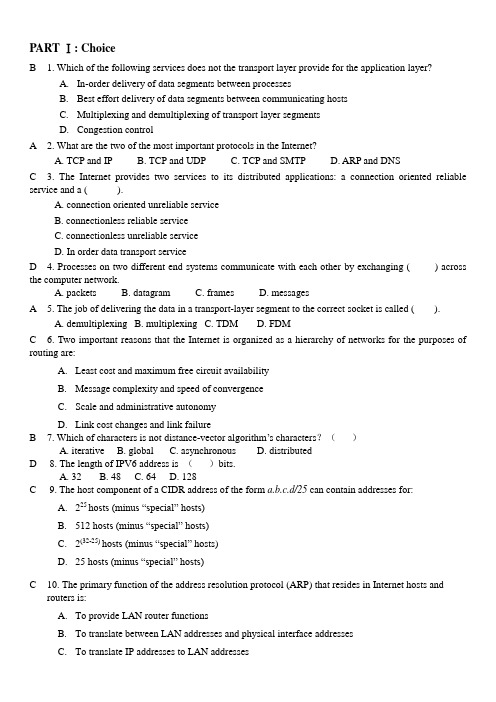
PART Ⅰ: ChoiceB 1. Which of the following services does not the transport layer provide for the application layer?A.In-order delivery of data segments between processesB.Best effort delivery of data segments between communicating hostsC.Multiplexing and demultiplexing of transport layer segmentsD.Congestion controlA 2. What are the two of the most important protocols in the Internet?A. TCP and IPB. TCP and UDPC. TCP and SMTPD. ARP and DNSC 3. The Internet provides two services to its distributed applications: a connection oriented reliable service and a ( ).A. connection oriented unreliable serviceB. connectionless reliable serviceC. connectionless unreliable serviceD. In order data transport serviceD 4. Processes on two different end systems communicate with each other by exchanging ( ) across the computer network.A. packetsB. datagramC. framesD. messagesA 5. The job of delivering the data in a transport-layer segment to the correct socket is called ( ).A. demultiplexingB. multiplexingC. TDMD. FDMC 6. Two important reasons that the Internet is organized as a hierarchy of networks for the purposes of routing are:A.Least cost and maximum free circuit availabilityB.Message complexity and speed of convergenceC.Scale and administrative autonomyD.Link cost changes and link failureB 7. Which of characters is not distance-vector algorithm’s characters?()A. iterativeB. globalC. asynchronousD. distributedD 8. The length of IPV6 address is ()bits.A. 32B. 48C. 64D. 128C 9. The host component of a CIDR address of the form a.b.c.d/25 can contain addresses for:A.225 hosts (minus “special” hosts)B.512 hosts (minus “special” hosts)C.2(32-25) hosts (minus “special” hosts)D.25 hosts (minus “special” hosts)C 10. The primary function of the address resolution protocol (ARP) that resides in Internet hosts androuters is:A.To provide LAN router functionsB.To translate between LAN addresses and physical interface addressesC.To translate IP addresses to LAN addressesD.To calculate the shortest path between two nodes on a LANA 11. The POP3 protocol runs over ____ and uses port ____.A. TCP 110B. UDP 110C. UDP 25D. TCP 25D 12.When a destination host transport layer receives data from the network layer, it unambiguouslyidentifies the appropriate process to pass the data to by using a triplet consisting of:A. Source port #, destination IP address, and source IP addressB. Destination port #, source port #, process ID#C. Destination port #, source port #, destination IP addressD. Destination port #, source port #, source IP addressD 13. From the list below, select the items found in the TCP segment structure that are not found in theUDP segment structure:A. Application Generated DataB. Destination Port #C. Source Port #D. Sequence #A 14. The RIP routing protocol is based on an algorithm that is:A. Based on information received only from link “neighbors”B. A link state algorithmC. An OSPF algorithmD. A centralized routing algorithmB 15. With an exterior routing protocol, which of the following issues generally dominates the routing decisions?A. Geographical distance between AS’sB. PolicyC. Number of AS’s traversedD. Current congestion levels in the AS’sA 1. End system are connected together by ____.A. communication linksB. application layerC. transport layerD. the network layerC 2. Which application’s NOT using TCP?A. SMTPB. HTTPC. DNSD. All of themB 3. In the polling protocols, the master node polls each of the nodes in a/an ____ fashion.A. randomB. appointedC. round-robinD. uncirculatedC 4. The DNS protocol runs over ____ and uses port ____.A. UDP 36B. TCP 36C. UDP 53D. TCP 53A 5. TCP provides a ____ service to its applications to eliminate the possibility of the sender over-flowingthe receiver’s buffer.A. flow-controlB. congestion controlC. reliability controlD. data connectionD 6. We can classify just about any multiple access protocol as belonging to one of three categories: channel partitioning protocols, random access protocols, and ____.A. address resolution protocolsB. Dynamic host configuration protocolsC. link-control protocolsD. taking-turns protocolsB 8. The maximum transfer unit(MTU) in Ethernet frame structure is ()byte .A. 1000B. 1500C. 800D. 2000B 9. The socket of UDP is identified by _____ and _______.A. source IP address and source port numberB. destination IP address and destination port number.C. source IP address and destination port number.D. destination IP address and source IP address.C 10. Which is not plug and play in the following four items?A. DHCPB. HubsC. RoutersD. SwitchesD 11.Which of routers is not default routers ?A. first-hop routerB. source routerC. destination routerD. second-hop routerB 13. ICMP is_____.A. the protocol of Application layerB. the protocol of network layerC. the protocol of transport layerD. not a part of TCP/IP protocolsB 14. As general, we has following channel partitioning protocols except ____.A. TDMB. CSMAC. FDMD.CDMAD 15. ____ is most used for error reporting.A. UDPB. SMTPC. FTPD. ICMPB 16. The header of IPV6 is ____byte.A. 20B. 40C. 60D. 80B 17. In the network layer these service are host-to-host service provided by ____. (B)A. the transport layer to the network layerB. the network layer to the transport layerC. the network layer to the network layerD. the transport layer to the transport layerA 18. If there is not enough memory to buffer an incoming packet , a policy that drop the arriving packet called ____.A. drop-tailB. packet lossC. protocolD. encapsulationC 19. In either case, a ____ receives routing protocol messages, which are used to configure its forwarding table.A. serverB. hostC. routerD. ModemD 20. Which of the following functions does not belong to PPP___.A. framingB. link-control protocolsC. network-control protocolsD. error correctionB 1. Which of the following services does the Internet network layer provide for the Internet transport layer?A.In-order delivery of data segments between processesB.Best effort delivery of data segments between communicating hostsC.Multiplexing and demultiplexing of transport layer segmentsD.Congestion controlD 2. The main task of the Internet’s Domain Name System (DNS) is to:A.Translate port numbers to IP addressesB.Specify the standards for Internet domain namesC.Provide an authority for registering domain namesD.Translate mnemonic(记忆的)names to IP addressesA 10. The FTP protocol runs over ____ and uses port ____.A. TCP 21B. TCP 80C. UDP 20D. TCP 110C 3.RDT3.0’s receiver FSM is same to:a) RDT1.0 b) RDT2.1 c) RDT2.2 d) RDT2.0B 4.The Transmission Control Protocol (TCP) provides which of the following services?a)End-to-end station addressingb)Application multiplexingc)Inter network routingd)Medium access control (MAC)D 6.Given that the requested information is not available at any intermediate databases, a non-iterated DNS query from a requesting host would follow the path:a)Root name server, local name server, authoritative name serverb)Authoritative name server, root name server, host name serverc)Local name server, root name server, local name server, authoritative name servere)Local name server, root name server, authoritative name serverA 8.lect the four essential steps, briefly described, for terminating a TCP connection between a client and a server, assuming that the initiating host is the client:(1)Client sends TCP segment with ACK0 and final sequence number(2)Client sends TCP segment with FIN =1 and goes into FIN_WAIT state(3)Server sends TCP segment to ACK the client’s FIN request and enters CLOSE_WAIT state(4)Server sends TCP segment with FIN=0(5)Server sends TCP segment with FIN=1(6)Client sends TCP segment with to ACK server’s FIN and enters second FIN_WAIT state(7)Client sends TCP segment with FIN=0a) 2,3,5,6 b) 5,1,2,3 c) 1,3,5,7 d) 2,3,4,6B 10.When compensating for link cost changes in the distance vector algorithm, it can generally be said that:a)Increased costs are propagated quickly, i.e., “bad news” travels fastb)Decreased costs are propagated rapidly, i.e., “good news” travels fastc)Decreased costs do not converged)None of the aboveB 14.As an IP datagram travels from its source to its destination:a)the source IP address is changed at each router to identify the sending routerb)the router uses the destination IP address to consult its routing tablec)the router does not use the IP addresses in the datagramd)the destination IP address is changed at each router to reflect the next hopC 15.From the list below, choose the bit pattern which could be a valid generator value for the CRC code (R) 11010:a)1110b)011010c)100101d)10011A 16.Consider sending a 1300 byte IPv4 datagram into a link that has an MTU of 500 bytes:a)Three fragments are created.b)Four fragments are created.c)Three fragments are created with offsets 0, 500 1000d)The last fragment consists of exactly 300 bytes of data from the original datagramC 17.Suppose one IPv6 router wants to send a datagram to another IPv6 router, but the two are connected together via an intervening IPv4 router. If the two routers use tunneling, then:a)The sending IPv6 router creates an IPv4 datagram and puts it in the data field of an IPv6datagram.b)The sending IPv6 router creates one or more IPv6 fragments, none of which is larger than themaximum size of an IPv4 datagram.c)The sending IPv6 router creates an IPv6 datagram and puts it in the data field of an IPv4datagram.d)The sending IPv6 router creates an IPv6 datagram and intervening IPv4 router will reject theIPv6 datagramD 18.Which of the following was an important consideration in the design of IPv6a)fixed length 40-byte header and specified options to decrease processing time at IPv6 nodesb)128-bit addresses to extend the address spacec)different types of service (flows) definedd)all of the aboveD 19.A network bridge table is used to perform the following:a)Mapping MAC addresses to bridge port numbersb)Forwarding frames directly to outbound ports for MAC addresses it handlesc)Filtering (discarding) frames that are not destined for MAC addresses it handlesd)All of the abovePART Ⅱ: True / False (1 points per question – total:20 points)1. The DNS server can update the records. (T)2. The TCP connection is a direct virtual pipe between the client’s socket and the server’s connection socket. (T)3. SMTP protocol connect the sender’s mail server and receiver’s mail server (T)4. Whereas a transport-layer protocol provides logical communication between processes running on different hosts, a network-layer protocol provides logical communication between hosts. (T)5. UDP and TCP also provide integrity checking by including right-detection fields in their headers. (F)6. If the application developer chooses UDP instead of TCP, then the application is not directly talking with IP. ( F )7. When we develop a new application, we must assign the application a port number. ( T )8. Real-tine applications, like Internet phone and video conferencing, react very poorly to TCP’s congestion control. ( T )9. The sender knows that a received ACK or NAK packet was generated in response to its most recently transmitted data packet. (T)10. To simplify terminology, when in an Internet context, we refer to the 4-PDU as a unit. (F)11. DV algorithm is essentially the only routing algorithm used in practice today in the Internet。
计算机网络英文课件Chapter1
client/server model
r r
peer-peer model:
r r
Network edge: connection-oriented service
Goal: data transfer
between end systems handshaking: setup (prepare for) data transfer ahead of time
Introduction 1-2
Chapter 1: roadmap
1.1 What is the Internet? 1.2 Network edge 1.3 Network core 1.4 Network access and physical media 1.5 Internet structure and ISPs 1.6 Delay & loss in packet-switched networks 1.7 Protocol layers, service models 1.8 History
protocols control sending,
receiving of msgs
r
router server local ISP
workstation mobile
e.g., TCP, IP, HTTP, FTP, PPP
Internet: “network of
networks”
r r
loosely hierarchical public Internet versus private intranet RFC: Request for comments IETF: Internet Engineering Task Force
Promoting the Use of End-to-End Congestion Control in the Internet

Promoting the Use of End-to-End Congestion Control in the InternetSally Floyd and Kevin FallSubmitted to IEEE/ACM Transactions on NetworkingFebruary10,1998AbstractThis paper considers the potentially negative impacts of an in-creasing deployment of non-congestion-controlled best-efforttraffic on the Internet.These negative impacts range fromextreme unfairness against competing TCP traffic to the po-tential for congestion collapse.To promote the inclusion ofend-to-end congestion control for best-effort traffic,we arguethat router mechanisms are needed to identify and restrict thebandwidth of selected high-bandwidth best-effortflows thatare using a disproportionate share of the bandwidth in timesof congestion.Starting with high-bandwidthflows in times of conges-tion,we describe a sequence of tests identifying those high-bandwidthflows suitable for bandwidth regulation.These testsidentify a high-bandwidthflow in times of congestion as unre-sponsive,“not TCP-friendly”,or simply using disproportion-ate bandwidth.An unresponsiveflow is one failing to reduceits offered load at a router in response to an increased packetdrop rate.Aflow that is not TCP-friendly is one whose long-term arrival rate exceeds that of any conformant TCP in thesame circumstances.A disproportionate-bandwidthflow isone that uses considerably more bandwidth than otherflows ina time of congestion,when there is suppressed demand fromsome of the otherflows.We end with a comparison betweenthis approach and others using per-flow scheduling for all best-effort traffic.1IntroductionThe end-to-end congestion control mechanisms of TCP havebeen a critical factor in the robustness of the Internet.How-ever,the Internet is no longer a small,closely knit user com-munity,and it is no longer possible to rely on all end-nodes toincreasing deployment of such traffic in the Internet.The In-ternet is now at a cross-roads in terms of the use of end-to-end congestion control for best-effort traffic,and is in a posi-tion to actively welcome the widespread deployment of non-congestion-controlled best-effort traffic,to actively discourage such a widespread deployment,or,by taking no action,to al-low such a widespread deployment to become a simple fact of life.We argue in this paper that recognizing the essential role of end-to-end congestion control for best-effort traffic and strengthening incentives for best-effortflows to use end-to-end congestion control are critical issues as the Internet expands to a larger community.As we show in Section2,an increasing deployment of traf-fic lacking end-to-end congestion control could lead to conges-tion collapse in the Internet.This form of congestion collapse would result from congested links sending packets that would only be dropped later in the network.The essential factor be-hind this form of congestion collapse is the absence of end-to-end feedback.Per-flow scheduling algorithms supply fairness with a cost of increased state,but provide no inherent incentive structure for best-effortflows to use strong end-to-end conges-tion control.Our approach,however,gives a low-overhead mechanism that also provides an incentive structure forflows to use end-to-end congestion control.The mechanisms discussed in this paper are suggested to help manage best-effort traffic only.We expect other traffic to use one of the“premium services”being added to the In-ternet.Examples of such premium services are the guaran-teed and controlled-load services currently under development in the IETF(Internet Engineering Task Force)[IET].These services are primarily for real-time or other traffic with partic-ular quality-of-service requirements,and require explicit ad-mission control and preferential scheduling in the network. Other examples of premium services under development in-clude more general differential services that would not require per-flow admissions controls.It seems likely(to us)that pre-mium services in general will apply only to a small fraction of future Internet traffic,and that the Internet will continue to be dominated by best-effort traffic.Section2discusses the problems of extreme unfairness and potential congestion collapse that would result from increas-ing levels of best-effort traffic not using end-to-end congestion control.Next,Section3describes a range of mechanisms for determining which high-bandwidthflows should be regulated by having their bandwidth use restricted at the router.The most conservative such mechanism identifies high-bandwidthflows that are not“TCP-friendly”(i.e.,that are using more band-width than would any conformant TCP implementation in the same circumstances).The second mechanism identifies high-bandwidthflows as“unresponsive”when their arrival rate at the router is not reduced in response to increased packet drops. The third mechanism identifies disproportionate-bandwidth flows,high-bandwidthflows that may be both responsive and TCP-friendly,but nevertheless are using excessive bandwidth in a time of high congestion.As mentioned above,a different approach would be the use of per-flow scheduling mechanisms such as variants of round-robin or fair queueing to isolate all best-effortflows at routers. Most of these per-flow scheduling mechanisms prevent a best-effortflow from using a disproportionate amount of bandwidth in times of congestion,and therefore might seem to require no further mechanisms to identify and restrict the bandwidth of particular best-effortflows.Section4compares the two ap-proaches,and discusses some advantages of aggregating best-effort traffic in queues using simple FIFO scheduling and RED queue management along with the mechanisms described in this paper.Section5gives conclusions and discusses some of the open questions.The simulations in this paper use the ns simulator,available at[MF95].The scripts to run these simulations are available from the Network Research Group web page[Gro97].2The problem of unresponsiveflows Unresponsiveflows areflows that do not use end-to-end con-gestion control,and in particular that do not reduce their load on the network when subjected to packet drops.This unre-sponsive behavior can result in both unfairness and congestion collapse for the Internet.The unfairness is from the bandwidth starvation that unresponsiveflows can inflict on well-behaved responsive traffic.The danger of congestion collapse comes from a network busy transmitting packets that will simply be discarded before reaching theirfinal destinations.We discuss these two dangers separately below.2.1Problems of unfairnessAfirst problem caused by the absence of end-to-end conges-tion control is the drastic unfairness that results from TCP flows competing with unresponsive UDPflows for scarce bandwidth.The TCPflows reduce their sending rates in re-sponse to congestion,leaving the uncooperative UDPflows to use the available bandwidth.3 ms1.5 Mbps2 ms10 Mbps10 MbpsR1S1S2R2S3S410 msX Kbps5 ms10 Mbps3 msFigure1:Simulation network.Figure2graphically illustrates what happens when UDP and TCPflows compete for bandwidth,given routers with FIFO scheduling.The simulations uses the scenario in Fig-ure1,with the bandwidth of the R2-S4link set to10Mbps.Solid Line: TCP Goodput; Bold line: Aggregate Goodput X-axis: UDP Arrival Rate (% of R1-R2). Dashed Line: UDP Arrivals; Dotted Line: UDP Goodput;G o o d p u t (% o f R 1-R 2)0.00.20.40.60.8 1.0 1.20.00.40.8xxxx x x x x x x x xx x xx x x x x xx x x x x x x x x xx x x x x x x x x x x x xx x x xxxxxx x x x x x x x x x x Figure 2:Simulations showing extreme unfairness with three TCP flows and one UDP flow,and FIFO scheduling.Solid Line: TCP Goodput; Bold line: Aggregate GoodputX-axis: UDP Arrival Rate (% of R1-R2). Dashed Line: UDP Arrivals; Dotted Line: UDP Goodput;G o o d p u t (% o f R 1-R 2)0.00.20.40.60.8 1.0 1.20.00.40.8x x x x x x x x x x x x x x x x x xxx x x x x x x xx x xxxxxx x x x x x x x x x xx x x x x x x x x x x x x x x x x x x x Figure 3:Simulations with three TCP flows and one UDP flow,with WRR scheduling.There is no unfairness.The traffic consists of several TCP connections from node S1to node S3,each with unlimited data to send,and a single constant-rate UDP flow from node S2to S4.The routers have a single output queue for each attached link,and use FIFO scheduling.The sending rate for the UDP flow ranges up to 2Mbps.Definition :goodput .We define the “goodput”of a flow as the bandwidth delivered to the receiver,excluding duplicate packets.Each simulation is represented in Figure 2by three marks,one for the UDP sending rate for that simulation,another for UDP goodput,and a third for TCP goodput.The -axis shows the UDP sending rate,as a fraction of the bandwidth on the R1-R2link.The dashed line shows the UDP sending rate for the entire simulation set,the dotted line shows the UDP goodput,and the solid line shows the TCP goodput,all expressed as a fraction of the available bandwidth on the R1-R2link.The bold line shows the aggregate goodput.As Figure 2shows,when the sending rate of the UDP flow is small,the TCP flows have high goodput,and use almost all of the bandwidth on the R1-R2link.When the sending rate of the UDP flow is larger,the UDP flow receives a correspond-ingly large fraction of the bandwidth on the R1-R2link,while the TCP flows back off in response to packet drops.This un-fairness results from responsive and unresponsive flows com-peting for bandwidth under FIFO scheduling.The UDP flow effectively “shuts out”the responsive TCP traffic.Even if all of the flows were using the exact same TCP congestion control mechanisms,with FIFO scheduling thebandwidth would not necessarily be distributed equally among those TCP flows with sufficient demand.[FJ92]discusses therelative distribution of bandwidth between two competing TCP connections with different roundtrip times.[Flo91]analyzes this difference,and goes on to discuss the relative distribu-tion of bandwidth between two competing TCP connections on paths with different numbers of congested gateways.For example,[Flo91]shows how,as a result of TCP's congestioncontrol algorithms,a connection's throughput varies as the in-verse of the connection's roundtrip time.For paths with multi-ple congested gateways,[Flo91]further shows how a connec-tion's throughput varies as the inverse of the square root of thenumber of congested gateways.Figure 3shows that per-flow scheduling mechanisms at the router can explicitly control the allocation of bandwidth among a set of competing flows.The simulations in Figure 3use same scenario as in Figure 2,except that the FIFO scheduling has been replaced with weighted round-robin (WRR)scheduling,with each flow assigned an equal weight.As Figure 3shows,with WRR scheduling the UDP flow is restricted to roughly 25%of the link bandwidth.The results would be similar withvariants of Fair Queueing (FQ)scheduling.2.2The danger of congestion collapseThis section discusses congestion collapse from undelivered packets,and shows how unresponsive flows could contribute to congestion collapse in the Internet.Informally,congestion collapse occurs when an increase in the network load results in a decrease in the useful work done by the network.Congestion collapse was first reported in the mid 1980s [Nag84],and was largely due to TCP connections unnecessarily retransmitting packets that were either in transit or had already been received at the receiver.We call the con-gestion collapse that results from the unnecessary retransmis-sion of packets classical congestion collapse .Classical con-gestion collapse is a stable condition that can result in through-put that is a small fraction of normal [Nag84].Problems with classical congestion collapse have generally been corrected by the timer improvements and congestion control mechanisms in modern implementations of TCP [Jac88].A second form of potential congestion collapse,congestion collapse from undelivered packets ,is the form of interest to us in this paper.Congestion collapse from undelivered packets arises when bandwidth is wasted by delivering packets through the network that are dropped before reaching their ultimate destination.We believe this is the largest unresolved danger with respect to congestion collapse in the Internet today.The danger of congestion collapse from undelivered packets is due primarily to the increasing deployment of open-loop applica-tions not using end-to-end congestion control.Even more de-structive would be best-effort applications that increased their sending rate in response to an increased packet drop rate (e.g.,using an increased level of FEC).We note that congestion collapse from undelivered packets and other forms of congestion collapse discussed in the follow-ing section differ from classical congestion collapse in that the degraded condition is not stable,but returns to normal once the load is reduced.This does not necessarily mean that the dan-gers are less severe.Different scenarios also can result in dif-ferent degrees of congestion collapse,in terms of the fraction of the congested links'bandwidth used for productive work.Solid Line: TCP Goodput; Bold line: Aggregate GoodputX-axis: UDP Arrival Rate (% of R1-R2). Dashed Line: UDP Arrivals; Dotted Line: UDP Goodput;G o o d p u t (% o f R 1-R 2)0.00.20.40.60.81.01.20.00.40.8x xx xxx xx x x x x xxx x xx xxxxx x x x x x x x x xxxxx x xx x x x x x x x x x xx x xx x xx x xx x x x x x x x x x x Figure 4:Simulations showing congestion collapse with three TCP flows and one UDP flow,with FIFO scheduling.Solid Line: TCP Goodput; Bold line: Aggregate GoodputX-axis: UDP Arrival Rate (% of R1-R2). Dashed Line: UDP Arrivals; Dotted Line: UDP Goodput;G o o d p u t (% o f R 1-R 2)0.00.20.40.60.81.01.20.00.40.8xxxx x x xx x x x xxxx x x x xxx x x x x x x x x xxxxxxx x x x x x x x x x x xx x xx x x x x xx x x x x x x x x x x Figure 5:Simulations with three TCP flows and one UDP flow,with WRR scheduling.There is no congestion collapse.Figure 4illustrates congestion collapse from undelivered packets,where scarce bandwidth is wasted by packets that never reach their destination.The simulation in Figure 4uses the scenario in Figure 1,with the bandwidth of the R2-S4link set to 128Kbps,9%of the bandwidth of the R1-R2link.Be-cause the final link in the path for the UDP traffic (R2-S4)is of smaller bandwidth compared to the others,most of the UDP packets will be dropped at R2,at the output port to the R2-S4link,when the UDP source rate exceeds 128Kbps.As illustrated in Figure 4,as the UDP source rate increases linearly,the TCP goodput decreases roughly linearly,and the UDP goodput is nearly constant.Thus,as the UDP flow in-creases its offered load,its only effect is to hurt the TCP (and aggregate)goodput.On the R1-R2link,the UDP flow ulti-mately “wastes”the bandwidth that could have been used by the TCP flow,and reduces the goodput in the network as a whole down to a small fraction of the bandwidth of the R1-R2link.Per-flow scheduling mechanisms at the router can not be re-lied upon to eliminate this form of congestion collapse in all scenarios.For a scenario as in Figure 5,where a single flow is responsible for almost all of the wasted bandwidth at a link,per-flow scheduling mechanisms are reasonably successful at preventing congestion collapse as well as unfairness.Figure 5shows the same scenario as in Figure 4,except the router uses WRR scheduling instead of FIFO scheduling.Because the UDP flow is restricted to 25%of the link bandwidth,there is a minimal reduction in the aggregate goodput.Solid Line: TCP Goodput; Bold line: Aggregate GoodputX-axis: UDP Arrival Rate (% of R1-R2). Dashed Line: UDP Arrivals; Dotted Line: UDP Goodput;G o o d p u t (% o f R 1-R 2)0.00.40.8x xx xx x x x x x x xxxx x x x xxx x x x x x x x x x xxxxx x xx x x x x x x x xx x x x x x x x xxx x x x x x x x x x x Figure 6:Simulations with one TCP flow and three UDP flows,showing congestion collapse with FIFO scheduling.Solid Line: TCP Goodput; Bold line: Aggregate GoodputX-axis: UDP Arrival Rate (% of R1-R2). Dashed Line: UDP Arrivals; Dotted Line: UDP Goodput;G o o d p u t (% o f R 1-R 2)0.00.20.40.60.81.01.20.00.40.8xxxx xx xx x x x x x x x x x xxxxx x x x x x x x x x x xxx x x x xxx x x x x x x x x xx x x x x x x x xx x xx x x x x x x x Figure 7:Simulations with one TCP flow and three UDP flows,showing congestion collapse with WRR scheduling.In contrast,in a scenario as in Figures 6and 7where a num-ber of unresponsive flows are contributing to the congestion collapse,per-flow scheduling does not completely solve the problem.Figures 6and 7show a different traffic mix that illus-trates some congestion collapse for a network with routers with either FIFO or Round Robin scheduling.In this scenario,there is one TCP connection from node S1to node S3,and three constant-rate UDP connections from node S2to S4.Figure 6shows FIFO scheduling,and Figure 7shows WRR scheduling.In Figure 6,in high load the aggregate goodput of the R1-R2link is only 10%of normal,and in Figure 7,the aggregate goodput of the R1-R2link is 35%of normal.Figure 8shows that the limiting case of a very large num-ber of very small bandwidth flows without congestion control could threaten congestion collapse in a highly-congested Inter-net regardless of the scheduling discipline at the router.For the simulations in Figure 8,there are ten flows,with the TCP flows all from node S1to node S3,and the constant-rate UDP flows all from node S2to S4.The -axis shows the number of UDP flows in the simulation,ranging from 1to 9.The -axis shows the aggregate goodput,as a fraction of the bandwidth on the R1-R2link,for two simulation sets,one with FIFO schedul-Number of UDP Flows (as a Fraction of Total Flows). Dotted Line: FIFO Scheduling; Solid Line: WRR SchedulingA g g r e g a t e G o o d p u t (% o f R 1-R 2)0.00.20.40.60.8xxxx xx xx xxxxxxxxx x Figure 8:Congestion collapse as the number of UDP flows increases.ing,and the other with WRR scheduling.For the simulations with WRR scheduling,each flow is as-signed an equal weight,and congestion collapse is created by increasing the number of UDP flows going to the R2-S4link.For scheduling partitions based on source-destination pairs,congestion collapse would be created by increasing the num-ber of UDP flows traversing the R1-R2and R2-S4links that had separate source-destination pairs.The essential factor behind this form of congestion collapse is not the scheduling algorithm at the router,or the bandwidth used by a single UDP flow,but the absence of end-to-end con-gestion control for the UDP traffic.The congestion collapse would be essentially the same if the UDP traffic somewhat stupidly reserved and paid for more than 128Kbps of band-width on the R1-R2link in spite of the bandwidth limitations of the R2-S4link.In a datagram network,end-to-end conges-tion control is needed to prevent flows from continuing to send when a large fraction of their packets are dropped in the net-work before reaching their destination.We note that conges-tion collapse from undelivered packets would not be an issue in a circuit-switched network where a sender is only allowed to send when there is an end-to-end path with the appropriate bandwidth.2.3Other forms of congestion collapseIn addition to classical congestion collapse and congestion collapse from undelivered packets ,other potential forms of congestion collapse include fragmentation-based congestion collapse ,congestion collapse from increased control traffic ,and congestion collapse from stale packets .We discuss these other forms of congestion collapse briefly in this section.Fragmentation-based congestion collapse [KM87,RF95]consists of the network transmitting fragments or cells of pack-ets that will be discarded at the receiver because they cannot be reassembled into a valid packet.Fragmentation-based con-gestion collapse can result when some of the cells or frag-ments of a network-layer packet are discarded (e.g.at the link layer),while the rest are delivered to the receiver,thus wasting bandwidth on a congested path.The danger of fragmentation-based congestion collapse comes from a mismatch betweenlink-level transmission units (e.g.,cells or fragments)and higher-layer retransmission units (datagrams or packets),and can be prevented by mechanisms aimed at providing network-layer knowledge to the link-layer or vice-versa.One such mechanism is Early Packet Discard [RF95],which arranges that when an ATM switch drops cells,it will drop complete packets of cells.Another mechanism is Path MTU discov-ery [KMMP88],which helps to minimize packet fragmenta-tion.A variant of fragmentation-based congestion collapse con-cerns the network transmitting packets received correctly by the transport-level at the end node,but subsequently dis-carded by the end-node before they can be of use of the end user [Var96].This can occur when web users abort partially-completed TCP transfers because of delays in the network and then re-request the same data.This form of fragmentation-based congestion collapse could result from a persistent high packet drop rate in the network,and could be ameliorated by mechanisms that allow end-nodes to save and re-use data from partially-completed transfers.Another form of possible congestion collapse,congestion collapse from increased control traffic ,has also been discussed in the research community.This would be congestion collapse where,as a result of increasing load and therefore increasing congestion,an increasingly-large fraction of the bytes trans-mitted on the congested links belong to control traffic (packet headers for small data packets,routing updates,multicast join and prune messages,session messages for reliable multicast sessions,DNS messages,etc.),and an increasingly-small frac-tion of the bytes transmitted correspond to data actually deliv-ered to network applications.A final form of congestion collapse,congestion collapse from stale packets ,could occur even in a scenario with infi-nite buffers and no packet drops.Congestion collapse from stale packets would occur if the congested links in the network were busy carrying packets that were no longer wanted by the user.This could happen,for example,if data transfers took sufficiently long,due to high delays waiting in large queues,that the users were no longer interested in the data when it fi-nally arrived.This could also happen if,in a time of increasing load,an increasing fraction of the link bandwidth was being used by push web data delivered to the client unnecessarily.2.4Building in the right incentivesGiven that the essential factor behind congestion collapse from undelivered packets is the absence of end-to-end congestion control,one question is how to build the right incentives into the network.What is needed is for the network architecture as a whole to include incentives for applications to use end-to-end congestion control.In the current architecture,there are no concrete incentives for individual users to use end-to-end congestion control,and there are in some cases “rewards”for users that do not useend-to-end congestion control,in that they might receive a larger fraction of the link bandwidth than they would other-wise.Given a growing consensus among the Internet com-munity that end-to-end congestion control is one of the funda-mental bases for the future health and survival of the Internet, there are some social incentives for protocol designers,soft-ware vendors,and the like not to produce products designed for the Internet that do not use end-to-end congestion control; it would not be good for business to be held responsible for the degradation on the Internet.However,it is not sufficient to depend only on social incentives such as these.Axelrod in“The Evolution of Cooperation”[Axe84]dis-cusses some of the conditions required if cooperation is to be maintained in a system as a stable state.One way to view congestion control in the Internet is as TCP connections co-operating to share the scarce bandwidth in times of conges-tion.The benefits of this cooperation are that cooperating TCP connections can share bandwidth in a FIFO queue,using sim-ple scheduling and accounting mechanisms,and can reap the benefits in that short bursts of packets from a connection can be transmitted in a burst.(FIFO queueing's tolerance of short bursts reduces the worst-case packet delay for packets that ar-rive at the router in a burst,compared to the worst-case delays from per-flow scheduling algorithms.)This cooperative be-havior in sharing scarce bandwidth is the foundation of TCP congestion control in the global Internet.The inescapable price for this cooperation to remain stable is for mechanisms to be put in place so that users do not have an incentive to behave uncooperatively in the long term.Be-cause users in the Internet do not have information about other users against whom they are competing for scarce bandwidth, the incentive mechanisms cannot come from the other users, but would have to come from the network infrastructure it-self.This paper explores mechanisms that could be deployed in routers to provide a concrete incentive for users to partici-pate in cooperative methods of congestion control.Alternative approaches such as per-flow scheduling mechanisms and re-liance on pricing structures are discussed later in the paper. Section3continues with mechanisms for identifying which of these high-bandwidthflows are sufficiently unresponsive that their bandwidth should be regulated at the router.3Identifyingflows to regulateIn this section,we discuss the range of policies a router might use to decide which high-bandwidthflows to regulate.For a router with RED queue management,the arrival rates of high-bandwidthflows can be efficiently estimated from the recent packet drop history at the router,as described in[FF97].The router only needs to consider regulating those best-effortflows using significantly more than their“share”of the bandwidth in the presense of suppressed demand(as evidenced by packet drops)from other best-effortflows.A router can“regulate”aflow's bandwidth by differentially scheduling packets from thatflow,or by preferentially dropping packets from thatflow at the router[LM96].When congestion is mild(as represented by a low packet drop rate),a router does not need to take any steps to identify high-bandwidthflows or further check if those flows need to be regulated.The tests in this section assume that a“flow”is defined on the granularity of source and destination IP addresses and port numbers,so each TCP connection is a singleflow.For a router in the interior of the network where a different granularity is used to define aflow,it will be necessary to use different poli-cies to identify a“flow”whose bandwidth should be regulated. An additional issue not addressed in this paper is that prac-tices such as encryption and packet fragmentation could make it problematic for routers to classify packets intofine-grained flows.The practice of packet fragmentation should decrease with the use of MTU discovery[MD90],but the practice of encryption[Atk95]is more likely to be increasing.The policies outlined in this section for regulating high-bandwidthflows range in the degree of caution.The most conservative policy would be only to regulate high-bandwidth flows in times of congestion when they are known to be vi-olating the expectations of end-to-end congestion control,by being either unresponsive to congestion or exceeding the band-width used by any conformant TCPflow under the same cir-cumstances.A less“conservative”policy would include regu-lating any high-bandwidthflow using significantly more than its“share”of the bandwidth in a time of high congestion. The router applies a set of tests to determines if the selected flow is unresponsive,not TCP-friendly,or“disproportionate-bandwidth”.If theflow meets the criteria for any of these tests, the bandwidth of theflow should be regulated by the router.3.1Identifyingflows that are not TCP-friendly Definition:TCP-friendlyflows.We say aflow is TCP-friendly if its arrival rate does not exceed the bandwidth of a confor-mant TCP connection in the same circumstances.The test of whether or not aflow is TCP-friendly assumes TCP can be characterized by a congestion response of reducing its conges-tion window at least by half upon indications of congestion (i.e.,packet drops),and of increasing its congestion window by a constant rate of at most one packet per roundtrip time otherwise.This response to congestion leads to a maximum overall sending rate for a TCP connection with a given packet loss rate,packet size,and roundtrip time.Given a non-bursty packet drop rateof,the maximum sending rate for a TCP connectionis Bps,for。
[congestion] design-difficult-to-route
Handling scenic nets
go very scenic = bad timing performance impose scenic constrains on the router
Lienig
VLSI Physical Design: From Graph Partitioning to Timing Closure
Chapter 6: Detailed Routing
7
What Makes a Design Difficult to Route
© KLMH
DETAILED ROUTING CONSTRAINTS Prediction failure in global routing hot sports predicted by global routing may not be open and shorts in detailed routing
REPEATER INSERTION TECHNIQUES
CONCLUSION
Lienig
VLSI Physical Design: From Graph Partitioning to Timing Closure
Chapter 6: Detailed Routing
2
What Makes a Design Difficult to Route
© KLMH
INTRODUCTION Modern technology requires complex wire spacing rules and constraints High performance routing requires multiple wire width (even same layer) Local problems including via spacing rules, switchbox inefficiency, intra-gcell routing
计算机网络英文复习题
计算机⽹络英⽂复习题、英译汉(10分)1.TCP(Transmission Control Protocol) 传输控制协议2.IP(Internet Protocol) 互联⽹协议3.RFC(Requests for comments) 请求评议4.SMTP(Simple Mail Transfer Protocol) 简单邮件传输协议5.Congestion-control 拥塞控制6.Flow control 流控制7.UDP (User Datagram Protocol) ⽤户数据报协议8.FTP(File Transfer Protocol) ⽂件传输协议9.HTTP( Hyper-Text Transfer Protocol ) 超⽂本传输协议10.TDM 时分复⽤11.FDM 频分复⽤12.ISP(Internet Service Provider) 互联⽹服务提供商13.DSL(Digital Subscriber Line) 数字⽤户线路14.DNS(Domain Name System) 域名系统15.ARQ(Automatic Repeat Request) ⾃动重发请求16.ICMP(Internet Control Message Protocol) ⽹间控制报⽂协议17.AS(Autonomous Systems) ⾃制系统18.RIP(Routing Information Protocol)\ 路由信息协议19.OSPF(Open Shortest Path First) 开放最短路径优先20.BGP (Border Gateway Protocol) 边界⽹关协议21.HFC 光纤同轴电缆混合⽹22.CRC(Cyclic Redundancy Check) 循环冗余检验23.CSMA/CD 带冲突检测的载波侦听多路存取24.ARP 地址解析协议25.RARP 反向地址解析协议26.DHCP 动态主机配置协议27.RTT 循环时间28.IETF(P5)互联⽹⼯程任务组29.URL(P88)统⼀资源定位30.API应⽤程序编程接⼝31.MIME多⽤途互联⽹邮件扩展1. DSL divides the communication link between the home and the ISP into three nonoverlapping frequency bands, a upstream channel is in _A_________.A)50 kHz to 1MHz band B) 1MHz to 2MHz bandC)4 kHz to 50kHz band D) 0 to 4kHz band2. As a data packet moves from the upper to the lower layers, headers are A .A) Added; B) subtracted; C) rearranged; D) modified3. What is the main function of the network layer? DA) node-to-node delivery; B) process-to-process message deliveryC) synchronization; D) updating and maintenance of routingtables4. Which of the following is the default mask for the address 168.0.46.201? BA) 255.0.0.0; B) 255.255.0.0; C) 255.255.255.0; D) 255.255.255.2555.A router reads theaddress on a packet to determine the next hop. AA) IP ; B) MAC; C) source; D)ARP6 .Which device can’t isolates the departme ntal collision domains. AA) Hub; B) switch; C) router; D) A and B7. Input port of a router don’t perform ____D____ functions.A) the physical layer functions B) the data link layer functionsC) lookup and forwarding function D) network management8. HTTP has a mechanism that allows a cache to verify that its objects are up to date. The mechanism is DA) persistent connections B) cookies C) Web Caching D) conditional GET9. A protocol layer can be implemented in ___D_____.A) software B) hardware C) a combination of the software and hardware D) All of the above10. A protocol has three important factors, they are_A______.A)syntax, semantics, order B) syntax, semantics, layerC)syntax, semantics, packet D) syntax , layer, packet11. There are two broad classes of packet-switched networks: datagram networks and virtual-circuit networks. The virtual-circuit networks forward packets in their switches use ___D___.A) MAC addresses B) IP addressesC) e-mail addresses D) virtual-circuit numbers12. TCP service model doesn’t provide ___D_______service.A) reliable transport service B) flow control serviceC) congestion-control service D) guarantee a minimum transmission rate service.13. Usually elastic applications don’t include____B______.A) Electronic mail B) Internet telephony14. A user who uses a user agent on his local PC receives his mail sited in a mail server by using _B___ protocol.A)SMTP B) POP3C)SNMP D) FTP15. Considering sliding-window protocol, if the size of the transmitted window is N and the size of the receiving window is 1,the protocol is BA) stop-and-wait protocol B) Go-Back-N protocolC) selective Repeat protocol D) alternating-bit protocol16. which IP address is effective___B______.A) 202,131,45,61 B) 126.0.0.1C) 192.268.0.2 D) 290.25.135.1217. if IP address is 202.130.191.33, subnet mask is 255.255.255.0,then subnet prefix is__D_____A) 202.130.0.0 B) 202.0.0.0C) 202.130.191.33 D)202.130.191.018.The command Ping s implemented with __B______messagesA) DNS B) ICMPC) IGMP D) RIP19. Which layer-function is mostly implemented in an adapter? __A________A) physical layer and link layer B) network layer and transport layerC)physical layer and network layer D) transport layer and application layer20. If a user brings his computer from Chengdu to Peking, and accesses Internet again. Now, __B_____ of his computer needs to be changed.A) MAC address B) IP addressC) e-mail address D) user address1. .traceroute is implemented with __B____messages.A) DNS B) ICMPC) ARP D) RIP2.A router reads the A address on a packet to determine the next hop.A. IP ;B. MAC;C. source;D.ARP3. There are two broad classes of packet-switched networks: datagram networks andvirtual-circuit networks. The virtual-circuit networks forward packets in their switches use ___D___.A) MAC addresses B) IP addressesC) e-mail addresses D) virtual-circuit numbersA) device interfaces with same subnet part of IP addressB) can’t physically reach each other without intervening a router.C)all of the devices on a given subnet having the same subnet address.D)A portion of an interface’s IP address must be determined by the subnet to which it is connected.5. if IP address is 102.100.100.32, subnet mask is 255.255.240.0,then subnet prefix is___A___A) 102.100.96.0 B) 102.100.0.0C) 102.100.48.0 D) 102.100.112.06 If a user brings his computer from chengdu to beijing, and accesses Internet again. Now,___B__ of his computer needs to be changed.A) MAC address B) IP addressC) e-mail address D) user address7.I nput port of a router don’t perform ____D___ functions.A) the physical layer functions B) the data link layer functionsC) lookup and forwarding function D) network management8.switching fabric is at the heart of a router, switching can be accomplished in a number of ways, donit include_D_A)Switching via memory B)Switching via crossbarC)Switching via a bus D) Switching via buffer9.if a host wants to emit a datagram to all hosts on the same subnet, then the datagram’s destination IP address is ___B__A)255.255.255.0 B) 255.255.255.255C)255.255.255.254 D) 127.0.0.110.The advantage of Circuit switching does not include________.A) small transmission delay B)small Processing costC) high link utilization D)no limited to format of message1.an ARP query sent to __A__A) local network B) all over the Internet.2. .packet-switching technologies that use virtual circuitsinclude__B___:A) X.25, ATM, IP B) X.25, ATM, frame relay.C) IPX, IP, ATM D) IPX, IP, TCP3. In Internet, _D_ protocol is used to report error and provide the information forun-normal cases.A) IP B) TCP C)UDP D) ICMP1.A is a Circuit-switched network.B. Datagram networkC. InternetD. virtual circuit network2.The store-and-forward delay is DA. processing delayB. queuing delayC. propagation delayD. transmission delay3.Which is not the function of connection-oriented service? DA. flow controlB. congestion controlC. error correctionD. reliabledata transfer4.The IP protocol lies in CA. application layerB. transport layerC. network layerD. link layer5.Which of the following is the PDU for application layer __B___A.datagram;B. message;C. frame;D.segment6.bandwidth is described in _B__A) Bytes per second B) Bits per secondC) megabits per millisecond D) centimeters7.A user who uses a user agent on his local PC receives his mail sited in a mail server by using __A__ protocol.A)SMTP B) POP3C)SNMP D) FTP8.As a data packet moves from the lower to the upper layers, headers are B.A)Added; B. subtracted; C. rearranged; D. modified三、填空题(每空1分,共22分 (注意:所有填空题不能写中⽂,否则中⽂答案对的情况1. link-layer address is variously called a LAN address, a MAC address, or a physical address.2 In the layered architecture of computer networking, n layer is the user of n-1 layer and the service provider of n+1 layer.A) n B) n+3 C) n+1 D) n-1四、判断题(每⼩题1分,共10分)1.√The services of TCP’s reliable data transfer founded on the services of theunreliable data transfer.2.√Any protocol that performs handshaking between the communication entitiesbefore transferring data is a connection-oriented service.3.× HOL blocking occur in output ports of router.4.√Socket is globally unique.5.√SMTP require multimedia data to be ASCII encoded before transfer.6.×The transmission delay is a function of the distance between the two routers.7.×IP address is associated with the host or router. SO one device only have one IPaddress.8. √In packet-switched networks, a session’s messages use the resources on demand, and Internet makes its best effort to deliver packets in a timely manner.9. ×UDP is a kind of unreliable transmission layer protocol, so there is not any checksum field in UDP datagram header.10.√Forwarding table is configured by both Intra and Inter-AS routing algorithmIP is a kind of reliable transmission protocol. F8.Forwarding table is configured by both Intra and Inter-AS routing algorithm.T9.Distance vector routing protocol use lsa to advertise the network which router10.RIP and OSPF are Intra-AS routing protocols T11.Packet switching is suitable for real-time services, and offers better sharing ofbandwidth than circuit switching F五、计算题(28 points)1.C onsider the following network. With the indicated link costs, use Dijkstra’s shortest-path algorithm to compute the shortest path from X to all network nodes.2 Given: an organization has been assigned the network number 198.1.1.0/24 and it needs todefine six subnets. The largest subnet is required to support 25 hosts. Please:●Defining the subnet mask; (2分) 27bits or 255.255.255.224●Defining each of the subnet numbers; which are starting from 0# (4分)198.1.1.0/27 198.1.1.32/27 198.1.1.64/27 198.1.1.96/27 198.1.1.128/27 198.1.1.160/27 198.1.1.192/27 198.1.1.224/27●Defining the subnet 2#’s broadcast address.(2分) 198.1.1.95/27Defining host addresses scope for subnet 2#. (2分) 198.1.1.65/27--198.1.1.94/273. Consider sending a 3,000-byte datagram into a link that has an MTU of 1500bytes.Suppose the original datagram is stamped with the identification number 422 .Assuming a 20-byte IP header,How many fragments are generated? What are their characteristics?(10分)。
1.1 The Origins of Congestion
Congestion Control in BBN Packet-Switched Networks John Robinson Dan Friedman Martha SteenstrupBolt Beranek and Newman,Inc.1Introduction1.1The Origins of CongestionWe define congestion in a packet network to be the state where performance degrades due to the saturation of a network resource. Resources required by packet networks en-compass the communication links between packet switches and the switches’computa-tional resources—processor cycles and buffer memory.The degradation arises when the network expends resources in doing work it can’t complete.Congestion arises for a number of reasons. The network may simply be underconfigured for the offered load.Underconfiguration can result from temporary failures elsewhere in the network,or it may be a busy-hour occur-rence,hence not worthy of reconfiguration. In a network whose resources have different capacities,when all the capacity of a high-speed link is directed over a lower-speed link, that link cannot carry the offered load.Such over-demand can also arise due to the funnel-ing together orflows from several incoming links to an outgoing link.Packet switches should be able to cope gracefully with these situations.They may simply discard the excess packets,relying on This work was supported in part by the De-fense Communications Agency under contract200-88-C-0005higher-level mechanisms to recover from the loss.They may attempt to provide feedback to the sources of the excess traffic,or force them to reduce their demand.When packets are discarded,traffic sources will generally retransmit them.Though this makes discard-ing a harmless policy,it can lead to further congestion as the retransmissions compete for resources along the path to the switch that discarded the packets.If the sources’retrans-mission strategies fail to adapt to the onset of congestion,the sources and network form a positive-feedback loop that exacerbates the situation discarding attempted to solve.For certain networks and congestion symptoms, the network can enter a state dubbed conges-tion collapse[Jac],where throughput drops to well below its level prior to the onset of congestion.1.2Types of Congestion Control Al-gorithmsWe distinguish congestion control techniques by two major components:how they detect congestion and how they propagate the feed-back to sources of traffic.In addition,we will briefly examine control-theoretic prop-erties of the algorithm.Most congestion control schemes that have been proposed deal with queue lengths as an indicator of congestion.As the offered loadat a resource approaches or exceeds its capac-ity,the queue of traffic awaiting that resource will build up.Eventually,buffer space will be exhausted,at which point traffic must be dropped.Note that simply dropping the ex-cess traffic is a means of congestion control. Most techniques seek to avoid this response, or at least to refine it.One slightly more elaborate approach is to drop traffic selectively as the resource satu-rates.First-comefirst-served(FCFS)queu-ing simply drops the new arriving traffic when the queue reaches its size limit in an attempt to control the excess demand on the congested resource.The fair queuing method [DKS]provides fair access to allflows us-ing a resource,and penalizes heavierflows by preferentially dropping traffic of theflow with the longest queue when the resource congests.Zhang’s“virtual clock”algorithm [Zha]is similar with respect to packet order-ing and dropping.Approaches that monitor queue lengths can respond to congestion only after it has occurred.The long queues are a symptom of congestion.The cause,resource overutiliza-tion,cannot be predicted by queue length. Schemes that attempt to predict the onset of congestion must instead look at resource utilization.With this approach,the packet switch can begin to take action before the resource reaches100%utilization and,ide-ally,prevent the congestion from occurring. Congestion control schemes also differ in how they distribute the information that con-gestion is occurring and traffic sources must slow down.The simplest method is merely to drop some of the packets at the point of conges-tion.Most packet networks allow this,as the packet forwarding service is presumed to be unreliable by the higher-layer protocols that use it.Hence,occasional lost packets, like those lost to data errors,are tolerable. Overuse of this method,however,can lead to worse congestion than that it attempts to cure,leading to collapse.Also,the conges-tion control algorithm’s assumptions about the traffic sources’ability and method used to recover from lost packets may not match well with those actually in use.The feedback is implicit:dropped pack-ets are an indication that some resource is congested,and the traffic sources should all slow down.Packets dropped due to er-rors,however,should not cause this,and the source has no method to distinguish these cases.Also,this model leads to a pris-oner’s dilemma:a non-cooperative traffic source can respond to lost traffic by increas-ing itsflow,and capture more of the con-gested resource.The fair queuing algorithm attempts to correct thisflaw by dropping traf-fic selectively in order to penalize these non-cooperating sources.Others have proposed explicit feedback methods to reduce offered traffic.The IP source quench indication is an explicit con-trol message sent from the point of conges-tion to the source of a dropped packet;this allows the source to differentiate between packet errors and congestion.One problem with this scheme is that it is not fail-safe—the lack of a source quench can either mean there is no congestion,or that the reverse path is itself congested and the indication can’t be returned promptly.The binary scheme proposed by Ramakr-ishnan and Jain[RaJ]provides feedback by collecting information about possible conges-tion as traffic travels through the network, and returns the indication either piggybacked on reverse protocol traffic or in a separate in-dication.Since the sender can always expectan indication of the congestion state of the flow,this method can be made fail-safe—if no returned indication one way or the other reaches a traffic source,it must make the pes-simistic assumption that the network is con-gested and reduce its traffic.A third method to propagate congestion in-formation is through an explicit update pro-tocol,whereby congestion state information is carried through the network with high priority and guaranteed by its own proto-col.The BBN Congestion Control algo-rithm chooses this method,adding conges-tion state information to the routing up-dates alreadyflooded through the network by packet switches[MRR].This method guar-antees that congestion indications are for-warded in a timely manner,independent of network utilization due to congesting traffic. Thefinal major distinguishing feature is more structural than algorithmic—how the offered traffic can be modulated in response to congestion indications.Some schemes (dropping,source quench,fair queuing,bi-nary)rely on the source host to respond to the congestion indication in an appropriate manner to reduce the saturating load.In part,this is a recognition that the internet architecture really provides no other point where traffic may be reliably controlled—since thefirst packet switch(IP router)is typically separated from the host by a net-work,the switch cannot enforce restrictions on that host’s traffic submission rate.The initial switch can,however,attempt to with-hold traffic from subsequent networks in the internet.The BBN packet switch has the ability to restrict the traffic coming from a host through its use of either the1822or X.25access pro-tocols[1822].The Congestion Control algo-rithm makes use of this ability to hold back congestingflows at their source.It has long been recognized[LaR]that quenchingflows at their source is preferable to trying to let them into the network and then stop them.The latter approach relies on traf-fic backing up from the point of congestion all the way to the source before the source will realize that it must lower its submission rate.The use of window-basedflow control protocols at the higher level will eventually stop someflows,but the assumption that this is sufficient isflawed for at least two reasons: 1.There may be no window-orientedflowcontrol in use for some of the congestingtraffic.2.In an uncongested network,theflow-control window size is ideally a func-tion of the propagation delay throughthe network.Aflow that traverses along-delay path requires a large windowto achieve high throughput;the largewindow means that thisflow will reactslowly to the buildup of network delaydue to congestion,especially when thecongestion occurs prior to the long de-lay.3.Related to this,since window-based al-gorithms cannot differentiate betweenthe delay due to congestion and that dueto normal propagation and queuing de-lay,they can’t choose a proper windowsize after the onset of congestion.Theyreduce their windows by an amount pro-portional to the current window size;thus,sources operating with larger win-dows due to normal delays may end upwith lower shares of the congested re-source.When traffic backs up behind the con-gested resource,many resources along thepath of theflow that should have been unaf-fected may become clogged with the backed-up traffic.Any local congestion control pol-icy must suffer from this problem.The BBN packet switch’s store-and-forward process originally adopted this va-riety of local congestion control scheme.It would simply drop without an acknowledg-ment packets that would cause an output queue to exceed its allowed length,exactly as though the packet had been damaged by a transmission error.This strategy takes advantage of the reliable link protocol,by which the upstream packet switch will re-transmit the packet after a timeout.Of the many problems of this approach, the gravest is that congestion will spread. Retransmissions triggered by downstream congestion use link bandwidth,reducing the effective capacity of a link that was not it-self congested.Retransmissions take priority over new transmissions,thus traffic routed over links other than the congested link at the downstream switch will see a reduction in throughput.If this reduction is enough, traffic that was not by itself a cause of the original congestion will nevertheless experi-ence congestion as the available capacity of resources it needs decreases due to other con-gesting trafficflows.Clearly,congestion can spread by this mechanism if many links in a network are operating near their capacity.A second problem is that choice of the re-transmit timeout for the sender depends on whether the retransmission is due to a data error or congestion.In the case of a data error,the packet should be retransmitted as soon as the sender knows that its acknowl-edgment won’t arrive,typically the round trip time for the link plus the worst-case packet processing time at the receiver.In the case of congestion,however,the retransmission would ideally arrive at the next switch when the congested resource has had an opportu-nity to reduce its queue.It might be better to back off,much as Ethernet transmitters do following a collision.The amount of back-off necessary depends on the degree of ex-cess demand,which the sender has no way of knowing given only the information that a packet was dropped.One could view some of the work in congestion control to date as an attempt to provide better heuristics to op-timize the back-off strategy in the face of congestion[Jac].A third problem is choice of the window size for the reliable link layer protocol.In the absence of congestion,this window should reflect the propagation delay over the line, plus anticipated processing time at the remote switch.For a long-delay line,the window must be large to allow high utilization of the link,but at the onset of congestion,the num-ber of packets to be dropped from this link can grow quite large before the sender has even noticed thefirst retransmission timeout.A fourth problem concerns the queue size limit.An output queue must be sufficient to allow the packet switch to run its out-put link at high utilization in the face of bursty arrivals from the incoming links and retransmissions due to errors on the output link.If the queue will also buffer traffic that must wait when the downstream switch is congested,it should perhaps be shortened, so that the congestion“indication”(dropped packets)can spread back toward the traffic source more quickly.The different uses of output buffer space conflict in choosing the correct limit.Finally,under extreme conditions,the packet-dropping strategy requires modifica-tion to the reliable link protocol.Exces-sive retransmission attempts in the absenceof congestion indicate that some systematic problem with the link,such as a data-pattern-dependent error,is preventing successful de-livery of the packet.To distinguish this case from congestion requires an extra protocol exchange between the two packet switches on the link so that downstream congestion doesn’t cause the link to be declared faulty. We also differentiate congestion control methods by the locality of their effects.For example,the BBN store-and-forward tech-nique is a local algorithm;a packet switch simply drops traffic when its output queues fill and relies on its neighbor to respond in some appropriate way.Router algorithms which simply drop IP datagrams have this sameflavor;the host must deduce the exis-tence of congestion from packet loss to make the appropriate response.The use of source quench and the binary scheme attempt to propagate congestion in-formation to the traffic sources explicitly. The amount of information in these cases is a one-bit indication,though it is possible to “integrate”the indication over time to deduce a properflow rate in response to this feed-back.Distributing explicit indications of re-source utilization propagates much more in-formation about the level of demand on re-sources throughout the network,and allows traffic sources to respond more rapidly and precisely to the onset of congestion anywhere in the network.Moreover,newflows can choose a proper sending rate prior to prob-ing the network path with traffic.Packet-dropping and source back-off are two open-loop control systems.The con-gested packet switch takes local action,in dropping packets,to control congestion,the rate of dropped packets.The traffic source takes local action,source back-off,in re-sponse to increased network delay.For this to work,of course,the dropping must even-tually affect the traffic sources or it will be completely futile;if all traffic sources re-spond to dropped traffic by sending faster, which they might do if they are trying to de-liver their traffic by a deadline,this form of control will fail altogether.Closed-loop systems provide explicit feed-back to the sources of traffic to set their traf-fic rates properly.For the host that must de-liver its traffic by a deadline,the feedback allows the host to estimate when its transfer will complete.If theflow rate will lead it to miss its deadline,it can take some other ac-tion,rather than attempting to force its traffic into the congested network.2The BBN Packet Switch Con-gestion Control algorithm Congestion control in the BBN packet switch is an anticipatory strategy1enforced by a distributed,closed-loop control algorithm. It uses global information about resource utilization to regulate the rates at which sourceflows enter a packet-switched net-work.In this context,flows are identi-fied by their source and destination packet switches,not by their source and destination hosts nor applications running on these hosts. Hence,data packets from multiple source hosts homed to a packet switch A sent to one or more destination hosts homed to a packet switch B constitute a single trafficflow be-tween A and B.The same algorithm could employ the other definitions offlow. Packet switches within a network collec-tively play the principal role in controlling congestion.Each packet switch periodically 1Others call it congestion avoidance[RaJ]computes,for each of its associated links and its CPU,the idealflow rate or ration based upon the desired versus measured utilization levels.(Hereafter,the term“resource”will always refer to a link or switch processor since these are the resources the Congestion Control algorithm monitors.)The resource ration is the maximum rate at which a single trafficflow may use the resource,with min-imal risk of congestion,and depends upon the capacity of the resource,the number of flows using the resource,and the size of each flow.The single ration per resource ensures that eachflow using a resource will obtain an equal share of it.Packet switches use resource rations to control trafficflow rates.Each packet switch receives resource rations from all resources in the network and computes its traffic sub-mission rate orflow ration for each destina-tion packet switch as the minimum of the col-lected rations for component resources along the source-destination path.A packet switch enforcesflow rations using throttlers,one per destination,that restrict the rate of traffic flow from the end-to-end subsystem to the store-and-forward network.The congestion control algorithm consists of three main components:resource ration computation,flow ration computation,and flow ration enforcement,which we describe in detail in the following sections.2.1Resource Ration Computation The objective of resource ration control is to maintain the average trafficflow through a resource at a rate that does not saturate the resource and yet does not severely re-strict throughput.A packet switch controls a resource ration by monitoring the current utilization of the resource and by adjusting the resource ration according to the perceived utilization.We have chosen a utilization-based instead of a delay-based performance measure to control the ration for three reasons.1.A congestion control strategy based ondelay is reactive rather than anticipatory,and hence slower to recognize conges-tion.When a resource becomes satu-rated,packets incur delay as they queuefor the resource.Congestion cannot becontrolled until it has occurred,as de-lay is a symptom and not a predictor ofcongestion.2.The high variance associated with delaymeasurements can result in instabilities,when delay is used to controlflow rates.3.It is difficult to design a fair congestioncontrol strategy based on delay.Con-trollingflows according to queuing de-lay measurements does not ensure fair-ness.Flows experiencing large delaysare not necessarily sources of conges-tion,although they might be affected bycongestion.Hence,by unconditionallyrestrictingflows that experience delay,apacket switch might unnecessarily limitnon-congestingflows.Resource rations control resource utiliza-tion indirectly.They affectflow rations, which regulate source trafficflow rates. These determine the load eachflow con-tributes to the resources along its source-destination path.For each time interval, each packet switch periodically updates each of its resource rations()according to the following control law:(0)=(+1)=min()()where represents the desired(target)re-source utilization level and()represents the measured resource utilization level over interval.The objective of the resource ration control law is to maintain resource utilization at the target level.When the measured utilization exceeds the target,the packet switch reduces the resource ration by the ratio of the de-sired to measured resource utilizations.Sim-ilarly,when the measured utilization drops below the target,the packet switch increases the resource ration by the ratio of desired to measured utilizations,provided the resulting ration does not exceed the target level.The ration adjustment ratio,(),has no upper bound but can never be less than, since measured resource utilization cannot exceed capacity.Hence,the parameter in the ration control law serves two separate purposes.It acts as the resource utilization set point,and it determines the maximum rate of ration reduction.A packet-switched network is a dynamic entity.The number and size of trafficflows and the routes over which they travel change with time.Under these conditions,a resource ration does not converge to a single value butfluctuates in response to changes in re-source utilization.However,given constant-rate traffic sources,the resource ration does converge to a single value by(repeated)ap-plication of the control law.The number of control law iterations required to achieve ra-tion convergence depends upon the number of individual trafficflows using the resource, the load offered by eachflow,and the uti-lization of the resource.A resource ration will converge to its proper value in one iteration of the control law,provided that the offered load does not exceed resource capacity and that allflows using the resource are greedy with respect to each of()(+1).(A greedyflow is one that always offers its full ration of traffic.)These conditions are sufficient for single-step ration convergence for the follow-ing reasons.When offered load is less than or equal to resource capacity,the measured utilization equals the offered load.Therefore, the ratio()is the correct factor by which to scale the rates of theflows using the re-source.Moreover,since allflows are greedy with respect to each of the rations computed at times and+1,eachflow will scale its rate by exactly this ratio.Thus,the com-bined offered load controlled by the newly computed ration will be equal to the target utilization level.If either the capacity or the greediness constraint is not met,ration con-vergence can require several applications of the control law.The ration reduction rate for a heavily-used resource is limited by the lower bound on the size of the ration adjustment ratio. Thus,the packet switch may have to apply the ration control law several times before the resource ration becomes low enough to affect theflow rates.Moreover,if the resource is saturated,the packet switch may reduce the ration below the correct value.The reason is that resource saturation results in exten-sive queuing for the affected resource,which delays a packet switch’s observations of the effect of its resource ration reductions.As long as a resource’s queue is non-empty,the packet switch measures the resource’s utiliza-tion at100%.Nevertheless,even if a ration undershoot occurs,one or two applications of the ration control law are usually sufficient to raise the resource ration to the correct value.Ration undershooting can be quickly cor-rected for the following reasons.There is no upper limit on the size of the ration ad-justment ratio other than that the resulting ration must not exceed the target,and hence ration values can be rapidly increased when measured utilization is low.Moreover,by properly limiting queue length at a saturated resource,one can reduce the delay in observ-ing the effects of ration reduction.To accelerate ration reduction in the pres-ence of high measured resource utilization, we have modified the original ration control law to include fast back-off by replacing uti-lization with offered load in the denominator. Unlike utilization,offered load can exceed capacity,which permits rations to be reduced at a rate faster than that dictated by the tar-get.Fast back-off uses estimates rather than actual measurements of the number offlows and the respective loads offered to compute an estimate of the total traffic offered to the resource.The estimate is computationally in-expensive yet still affords reasonable accu-racy.The modified resource ration computation, including fast back-off,is as follows.As long as the resource is not saturated,the packet switch invokes the original ration con-trol law to recompute the resource ration. Whenever the resource becomes saturated, the packet switch applies fast back-off to reduce the resource ration.To accommo-date potential roundoff errors,the packet switch defines saturation as average utiliza-tion greater than97%of the resource’s ca-pacity.With fast back-off,the packet switch as-sumes that it has underestimated by one the number of greedyflows using the resource. The packet switch then estimates the load of-fered to the resource as+(),where is the load contributed by theflows already ac-counted for and()is the load contributed by theflow previously unaccounted for.This estimate of resource offered load can exceed the capacity of the resource.Thus,with fast back-off,the ration adjustment ratio be-comes+(),facilitating rapid convergence;is no longer the lower limit on the ration adjustment ratio.The complete ration computation rule ap-plied by a packet switch to update one of its resource rations is as follows:(0)=;when()97%,(+1)=min()();when()97%,(+1)=minmax()+()()The maximum in the denominator helps en-sure fast ration reduction when the ration is less than();in this case,measured utilization exceeds estimated offered load.2.1.1Resource Utilization Measurement The link and processor rations computed by a packet switch are based upon the utiliza-tion of each resource measured during the preceding measurement interval.To mea-sure resource utilization,the packet switch obtains a set of sample measurements and av-erages them uniformly over the interval.For a transmission link,each sample corresponds to the actual number of bits transmitted dur-ing a givenfive-second sample period.For the CPU,each sample corresponds to the per-centage of busy time during a givenfifteen-second sample period,where busy time isderived from idle time,the amount of time spent in the lowest priority packet switch pro-cess.Selecting an appropriate measurement in-terval involves tradeoffs between stability and responsiveness.A longer measurement interval smooths out transients in the uti-lization measurements,but limits the speed at which actual changes in utilization can be captured in the measurement.A shorter measurement interval yields an average re-source utilization value that is accurate in the shorter-term,allowing the ration control law to trackfluctuations in utilization;however, it will respond to transients.For each resource,the measurement inter-val is specified as a multiple of the sample period for that resource.The recommended measurement intervals for links and for the processor are the corresponding sample pe-riod multiples closest to the routing update generation interval,since resource rations are recomputed once per update generation inter-val as described in the following section. 2.2Flow Ration ComputationThe frequency of resource ration computa-tion plays a key role in stabilizing the con-gestion control algorithm.To promote sta-bility,the interval between successive appli-cations of the ration control law should be long enough to enable the packet switch to observe the effect of its previous resource ra-tion on the resource utilization level.When a resource is saturated and there is exten-sive queuing at the given resource and at up-stream resources,the packet switch is unable to observe the effect of its ration reductions until the queues empty.If it takes a long time for the packet switch to observe the ef-fect of resource ration reduction,the ration might fall below the correct point.However, the corresponding reduction in throughput is temporary;the packet switch takes corrective action in the next iteration of the resource ra-tion computation rule,once it has measured low resource utilization.The routing update generation interval is the period at which a packet switch recom-putes routing metrics for its links and rations for its resources and is currently set at ten seconds.At the conclusion of a routing up-date generation interval,the packet switch generates an update packet containing the newly computed metrics and rations,only if either its metrics or its rations have changed significantly from the most recently recorded values.If update generation is not required, the packet switch discards the newly com-puted metrics and rations and retains the pre-vious values.In general,the update genera-tion interval is long enough for the effects of the previous resource ration to be observable at the given resource.In the current implementation of the con-gestion control algorithm,each packet switch distributes ration and routing information in a single update packet.Update packets areflooded throughout the network so that the delay between update generation at one packet switch and update reception at all other packet switches is usually less than a second,even for large networks.After re-ceiving resource rations in an update packet, a packet switch computes a newflow ration for each destination by traversing its routing tree and determining the minimum resource ration on the path to the destination.In the current implementation,there is a minimum period of two seconds between successive re-computations offlow rations,in order to limit the amount of processing devoted toflow ra-tion computation.。
ch2(TCP拥塞控制)_987508285
7
Why do We Care About Congestion Control?
Otherwise you get to congestion collapse How might this happen? - Assume network is congested (a router drops packets) - You learn the receiver didn’t get the packet • either by ACK, NACK, or Timeout - What do you do? retransmit packet - Still receiver didn’t get the packet - Retransmit again - …. and so on … - And now assume that everyone is doing the same!
2
Overview
Window Flow Control Analysis of TCP Congestion Control Tahoe, Reno, NewReno, Sack, Vegas Beyond TCP Congestion Control
3
Problem
Flow control - make sure that the receiver can receive as fast as you send Congestion control - make sure that the network delivers the packets to the receiver
6
Source rate
Limit the number of packets in the network to window W Source rate =
- 1、下载文档前请自行甄别文档内容的完整性,平台不提供额外的编辑、内容补充、找答案等附加服务。
- 2、"仅部分预览"的文档,不可在线预览部分如存在完整性等问题,可反馈申请退款(可完整预览的文档不适用该条件!)。
- 3、如文档侵犯您的权益,请联系客服反馈,我们会尽快为您处理(人工客服工作时间:9:00-18:30)。
Congestion Propagation among Routers in the Internet Kouhei Sugiyama,Hiroyuki Ohsaki and Makoto ImaseGraduate School of Information Science and Technology,Osaka University 1-5,Yamadaoka,Suita,Osaka,565-0871,JapanTel:+81-6-6879-4552Fax:+81-6-6879-4554E-mail:{k-sugi,oosaki,imase}@ist.osaka-u.ac.jpKeywords:Congestion Propagation,TCP(Transmission Control Protocol),Router,Nonlinear Phenomena,Ring Net-workAbstractIn recent years,various non-linear phenomena of the Internet have been discovered.For instance,it is reported that conges-tion of a router propagates to neighboring routers like a wave. Several researches on congestion propagation among routers have been performed.However,in these researches,cause of congestion propagation and condition that congestion propa-gation occurs have not been sufficiently investigated.In this paper,we reveal a cause of congestion propagation,and also investigate under what conditions congestion propagation is observed.Consequently,we show that speed of congestion propagation is affected by the bandwidth and the propagation delay of links,and that periodicity of congestion propagation becomes less obvious as randomness of network traffic in-creases.1IntroductionThe Internet is a huge non-linear system,and non-linear dynamics of the Internet has been attracting attention.In re-cent years,it has been reported that various non-linear phe-nomena are observed in the Internet.For instance,it has been reported that the Ethernet traffic in the Internet has self-similarity[1,2],time variation of TCPflow’s window size exhibits a chaotic behavior[3],and congestion of a router propagates to neighboring routers like a wave[4]. Congestion propagation among routers is a phenomenon that congestion propagates from a congested router to neigh-boring non-congested routers like a wave.An example of con-gestion propagation is illustrated in Fig.1.Once the router1 is congested,routers2,3,4,and5will be soon congested and the congestion of the router1will be relieved.Similarly routers6,7,8,and9will then be congested and congestion of routers2,3,4,and5will be relieved.Several researches regarding congestion propagation among routers in the Internet have been performed[5,6].The authors of[5]observed congestion propagation in a real net-work.The authors of[6]investigate congestion propagation through simulation experiments.As shown in Fig.2,contin-uous TCP traffic is generated from router i(1≤i≤N)toFigure1:Example of congestion propagation in the Internet router i−1(and from router1to router N)in a ring network where nodes are connected by unidirectional links.It is shown in[6]that congestion propagation is observed,and that each TCPflow’s transmission ratefluctuates periodically.In these researches,however,it has not been revealed why conges-tion propagation occurs and under what conditions conges-tion propagation occurs.In this paper,we therefore reveal a cause of congestion propagation among routers,and also investigate under what conditions congestion propagation is observed.We use the same ring network with that in[6].To clarify conditions that congestion propagation occurs,we perform simulations while changing several network parameters and system parameters. In particular,we clarify the effect of system parameters(i.e., link bandwidth,propagation delay,and router buffer size)and network protocols(i.e.,queue management mechanism such as DropTail and RED,and TCP protocol version)on conges-tion propagation among routers.In this paper,we will use a qualitative approach for investi-gating congestion propagation among ly,we vi-sually examine evolutions of the queue length of each router and the transmission rate of each TCPflow for investigating a cause of congestion propagation among routers.Note that although results are not included in this paper due to space limitation,we confirmed validity of ourfindings using a quan-titative approach—spectral analysis[7]of the queue lengthiFigure2:Simulation modelof each router and the transmission rate of each TCPflow. The organization of this paper is as follows.In Section2, we show an example of congestion propagation using simu-lation experiments.In Section3,we discuss a cause of con-gestion propagation among routers.In Section4,we perform several simulations while changing network parameters and system parameters.Consequently,we reveal a cause and con-ditions of congestion propagation.Finally,in Section5,we conclude this paper and discuss future work.2Congestion Propagation among Routers The network model used for simulation is shown in Fig.2. Similar to[6],we use a ring network where N routers are con-nected by unidirectional links.In what follows,i-th(1≤i≤N)router is called router i.As shown in Fig.2,TCPflow i (1≤i≤N)continuously transfers data from the router i to the router i−1(and from the router1to the router N).Note that there are N TCPflows although only the TCPflow from the router i to the router i−1is shown in Fig.2.We believe that simulations using a ring network is useful to reveal fun-damental characteristics of congestion propagation since this ring network is symmetric system.The parameter configura-tion used in simulation is shown in Tab.1.Unless explicitly stated,parameters shown in Tab.1are used in the following simulations.ns-2(version2.28)[8]was used for simulation. Figure3shows the evolution of the queue length(i.e.,the number of packets in the buffer)of each router.In Fig.3,the x-axis is time and the y-axis is router identifier i.In thefigure, the queue length of the router measured every10[s]is shown with brightness of a color.Thisfigure shows that the conges-tion of a router(i.e.,increase/decrease of the queue length) repeatedly propagates to other routers.Thisfigure also shows that variation in the queue length propagates from a down-Table1.Parameter configuration used in simulation Number of nodes N10Link bandwidth B10[Mbit/s]Propagation delay of a linkτ31[ms]Buffer size of a router L300[packet]Queue management mechanism DropTailPacket length S552[byte]TCP version TCP Tahoe30025020015010050Time [s]RouteridentifierQueue length [packet]0 200 400 600 800 100012345678910Figure3:Evolution of queue length of routers(B= 10[Mbit/s])stream router to an upstream router(i.e.,from router i to router i−1).From these observations,wefind that the con-gestion of a router regularly propagates from a downstream router to an upstream router.Figure4shows the evolution of the transmission rate of each TCPflow.In Fig.4,the x-axis is time and the y-axis is TCPflow’s identifier i.In thefigure,TCPflow’s transmis-sion rate measured every10[s]is shown with brightness of a color.Thisfigure shows that variation of TCPflow’s trans-mission rate repeatedly propagates to other TCPflows.This figure also shows that variation in TCPflow’s transmission rate propagates from a downstreamflow to an upstreamflow similar to the variation in the queue length of a router.By comparing Figs.3and4,one canfind that both conges-tion propagation and TCPflow’s transmission ratefluctuate with the same cycle.From these observations,it is expected that congestion propagation might cause periodic variation of TCPflow’s transmission rate,or vice versa.In the next section,we will discuss a cause of congestion propagation in the ring network.3 2.5 2 1.5 1 0.5 0Time [s]T C P f l o w i d e n t i f i e rTransmission rate [Mbit/s]200400600800100012 3 4 5 6 7 8 910Figure 4:Evolution of TCP flow’s transmission rate (B =10[Mbit/s])0 50 100 150 200 250 300 350 400 0200400 600 800 10000.51 1.52 2.53 3.54Q u e u e l e n g t h [p a c k e t ]T r a n s m i s s o n r a t e [M b i t /s ]Time [s]queue length transmission rateFigure 5:Evolutions of queue length of router 1and TCP flow1’s transmission rate3A Cause of Congestion PropagationThe evolutions of the queue length of the router 1(Fig.3)and TCP flow 1’s transmission rate (Fig.4)are shown in Fig.5.One can find from Fig.5that the queue length of a router and TCP flow’s transmission rate fluctuate almost syn-chronously.One can also find that variation of TCP flow’s transmission rate is slightly (approximately 10[s])earlier than that of the queue length of a router.From these observa-tions,we expect that congestion propagation among routers is caused by periodic variation of TCP flow’s transmission rate.We then investigate why TCP flow’s transmission rate fluc-tuates periodically.From Figs.3and 5,one can observe a strong positive correlation between the variation of TCP flow 1’s transmission rate and the variation of the queue length of the router 1.This implies that when TCP flow 1’s transmis-sion rate is high,many packets sent from the TCP flow 1are likely to be stored (i.e.,buffered)in the queue of the router 1.Let us assume that the TCP flow i has the largest transmis-sion rate among all TCP flows.In this case,many packets sent from the TCP flow i are queued in the buffer of the router i .Hence,once the queue of the router i overflows,packets sent from the TCP flow i are most likely to be discarded .When TCP flow i ’s packet is discarded,the TCP flow i will decrease its transmission rate because of its window-based flow control.Since the TCP flow i ’s transmission rate was largest just before the packet loss,when the TCP flow i de-creases its transmission rate,the queue length of the router i will be decreased greatly.At this moment,the TCP flow i −1,which is closest to the router i,is more likely to queue more packets than other TCP flly,among all TCP flows,the TCP flow i −1is most likely to increase its transmission rate after TCP flow i ’s transmission rate decrease.By repeating such procedures,variation of TCP flow i ’s transmission rate propagates to the TCP flow i −1.Thus,variation of TCP flow’s transmission rate propagates from a downstream flow to an upstream flow.4Effect of System and Network Parameters on Congestion PropagationIn this section,we perform simulation experiments while changing various network parameters and system parameters.In particular,we clarify the effect of system parameters (i.e.,link bandwidth,propagation delay of links,and router buffer size)and network protocols (i.e.,queue management mecha-nism such as DropTail and RED,and TCP protocol version)on congestion propagation among routers.4.1Effect of System ParametersWe first investigate the effect of system parameters (i.e.,link bandwidth,propagation delay of links,and router buffer size)on congestion propagation among routers.Figures 6and 7show evolutions of the queue length of a router and TCP flow’s transmission rate when link band-widths of all links are uniformly set to B =1[Mbit/s].In Figs.3(B =10[Mbit/s])and 6(B =1[Mbit/s]),the queue length of a router fluctuates periodically (i.e.,conges-tion propagates to other routers)regardless of the link band-width.However,by comparing Figs.3(B =10[Mbit/s])and 6(B =1[Mbit/s]),one can find that the cycle of congestion propagation among routers in Fig.6is as three times as that in Fig.3.Similarly,the cycle of the variation of TCP flow’s transmission rate in Fig.7is also as three times as that in Fig.4.Such a difference is probably caused by the difference300 250 200 150 100 50 0Time [s]R o u t e r i d e n t i f i e rQueue length [packet]200400600800100012 3 4 5 6 7 8 910Figure 6:Evolution of queue length of routers (B =1[Mbit/s]) 3 2.5 2 1.5 1 0.5 0Time [s]T C P f l o w i d e n t i f i e rTransmission rate [Mbit/s]200400 600 800100012 3 4 5 6 7 8 910Figure 7:Evolution of TCP flow’s transmission rate (B =1[Mbit/s])in TCP flow’s round-trip times.Although results are not included due to space limitation,congestion propagation among routers was observed when the propagation delay is set to τ=55[ms]and when the router buffer size is set to L =600[packet].However,the cycle of congestion propagation is different in every case.Such a difference in cycles of congestion propagation among routers is also caused by difference in TCP flow’s round-trip times.Note that these results are in agreement with the ana-lytic result in [6].From these observations,we conclude that system pa-rameters (i.e.,link bandwidth,propagation delay,and router300 250 200 150 100 50 0Time [s]R o u t e r i d e n t i f i e rQueue length [packet]200 400 600 800 100012 3 4 5 6 7 8 910Figure 8:Evolution of queue length of routers with TCP traf-fic randomness (B =10[Mbit/s])buffer size)do not affect occurrence of congestion propaga-tion among routers and that the cycle of congestion propaga-tion among routers is determined by TCP flow’s round-trip time.4.2Effect of TCP Traffic RandomnessWhen multiple TCP flows are accommodated in a DropTail router,a phenomenon such that behaviors of TCP flows syn-chronize (i.e.,phase effect)is known [9].It is known that the phase effect disappears when TCP traffic has some random-ness [9].For instance,when the timing of packet transmission from TCP source hosts is randomly delayed,the phase effect disappears.As we have discovered in Section 3,congestion prop-agation among routers is caused by the periodic variation of TCP flow’s transmission rate.If the periodicity of TCP flow’s transmission rate disappears by adding randomness to TCP traffic,it is expected that congestion propagation among routers may disappear.We therefore performed simulation by adding a random de-lay to the timing of packet transmission from a TCP source host.Specifically,a random delay of 0–0.1[s]was added at the time of packet transmission from TCP source hosts.Figures 8and 9show evolutions of the queue length of a router and TCP flow’s transmission rate.By comparing Figs.3and 8,one can find that although congestion propaga-tion among routers can still be observed,periodicity in Fig.8is less obvious than in Fig.3.From these observations,we conclude that although the pe-riodicity of congestion propagation among routers becomes less obvious by adding randomness to TCP traffic,conges-tion propagation does not disappear.3 2.5 2 1.5 1 0.5 0Time [s]T C P f l o w i d e n t i f i e rTransmission rate [Mbit/s]200400600800100012 3 4 5 6 7 8 910Figure 9:Evolution of TCP flow’s transmission rate withTCP traffic randomness)(B =10[Mbit/s]) 300 250 200 150 100 50 0Time [s]R o u t e r i d e n t i f i e rQueue length [packet]200400600800100012 3 4 5 6 7 8 910Figure 10:Evolution of queue length of routers (case of REDrouter)(B =10[Mbit/s])4.3Effect of Router’s Queue Management Mechanism As another method for preventing the phase effect with a DropTail router,active queue management mechanisms such as RED (Random Early Detection)have been proposed [10–13].We performed simulation by changing queue man-agement mechanism of a router from DropTail to RED.In the case with RED routers,evolutions of the queue length of a router and TCP flow’s transmission rate are shown in Figs.10and 11,respectively.By comparing Figs.3and 10,one can find that although congestion propagation among routers can still be observed,periodicity in Fig.10is less ob-vious than in Fig.3.3 2.5 2 1.5 1 0.5 0Time [s]T C P f l o w i d e n t i f i e rTransmission rate [Mbit/s]200 400 600 800 100012 3 4 5 6 7 8 910Figure 11:Evolution of TCP flow’s transmission rate (case ofRED router)(B =10[Mbit/s])From these observations,we conclude that although the pe-riodicity of congestion propagation becomes less obvious by setting the queue management mechanism of a router to RED,congestion propagation does not disappear.4.4Effect of TCP Protocol VersionFinally,we investigate the effect of TCP protocol version on congestion propagation.There are several TCP protocol versions,and each of which adopts a different congestion control mechanism.TCP proto-col versions may affect congestion propagation.Evolutions of the queue length of a router and TCP flow’s transmission rates are shown in Figs.12and 13.In these fig-ures,TCP Vegas [14]was used instead of TCP Tahoe.Figure 12indicates that congestion propagation almost dis-appear in the case of TCP Vegas.Also,one can find that the periodicity of TCP flow’s transmission rate in Fig.13cannot be observed.Although results are not included due to space limitation,when TCP NewReno and TCP Reno were used instead of TCP Tahoe,evolutions of the queue length of a router and TCP flow’s transmission rate are almost identical to the re-sults with TCP Tahoe (Figs.3and 4).From these observations,we conclude that changing the TCP protocol version to TCP Vegas diminishes congestion propagation.5Conclusion and Future WorkIn this paper,we have revealed a cause of congestion propagation among routers in the ring network.We have performed simulation experiments while changing several network parameters and system parameters.Consequently,300 250 200 150 100 50 0Time [s]R o u t e r i d e n t i f i e rQueue length [packet]200400600800100012 3 4 5 6 7 8 910Figure 12:Evolution of queue length of routers (case of TCPVegas)3 2.5 2 1.5 1 0.5 0Time [s]T C P f l o w i d e n t i f i e rTransmission rate [Mbit/s]200400 600 800100012 3 4 5 6 7 8 910Figure 13:Evolution of TCP flow’s transmission rate (case ofTCP Vegas)we have found:(1)speed of congestion propagation among routers is affected by the link bandwidth and the propagation delay of links,and (2)periodicity of congestion propagation among routers becomes less obvious as randomness of net-work traffic increases.As future work,we need to clarify other cause of conges-tion propagation among routers.Also,it is necessary to quan-titatively evaluate the effect of congestion propagation among routers on TCP flow’s end-to-end performance.Investigation of congestion propagation among routers in more general net-work topology is also necessary.AcknowledgmentsThe authors would like to thank Mr.Osamu Okumura of Osaka University,Japan for his kind support and valuable dis-cussions.References[1]W.E.Leland,M.S.Taqqu,W.Willinger,and D.V .Wil-son,“On the self-similar nature of Ethernet traffic (ex-tended version),”IEEE /ACM Transactions on Network-ing ,vol.2,pp.1–15,Feb.1994.[2]M.E.Crovella and A.Bestavros,“Self-similarity inWorld Wide Web traffic:Evidence and possible causes,”IEEE /ACM Transactions on Networking ,vol.5,pp.835–846,May 1997.[3]A.Veras and M.Boda,“The chaotic nature of TCP con-gestion control,”in Proceedings of IEEE INFOCOM ,vol.3,pp.1715–1723,Mar.2000.[4]D.E.Newman,N.D.Sizemore,V .E.Lynch,and B.A.Carreras,“Growth and propagation of disturbances in a communication network model,”in Proceedings of the 35th Hawaii International Conference on System Sci-ences (HICSS-35),pp.867–874,Jan.2002.[5]K.Fukuda,H.Takayasu,and M.Takayasu,“Spatialand temporal behavior of congestion in Internet traffic,”Fractals ,vol.7,pp.23–31,Mar.1999.[6]J.Steger,P.Vaderna,and G.Vattay,“On the propaga-tion of congestion waves in the Internet,”Physica A ,vol.359,pp.784–792,Jan.2006.[7]J.W.Cooley and J.Tukey,“An algorithm for the ma-chine calculation of complex fourier series,”Mathemat-ics of Computation ,vol.19,pp.297–301,Apr.1965.[8]“The network simulator –ns2.”Also available as/nsnam/ns/.[9]S.Floyd and V .Jacobson,“On traffic phase effects inpacket-switched gateways,”Internetworking:Research and Experience ,vol.3,pp.115–156,Sept.1992.[10]S.Floyd and V .Jacobson,“Random early detectiongateways for congestion avoidance,”IEEE /ACM Trans-actions on Networking ,vol.1,pp.397–413,Aug.1993.[11]S.Floyd,“Recommendations on using the gentle variantof RED,”May 2000.Also available as /floyd/red/gentle.html.[12]J.Aweya,M.Ouellette,and D.Y .Montuno,“A controltheoretic approach to active queue management,”Com-puter Networks ,vol.36,pp.203–235,July 2001.[13]S.Athuraliya,V .H.Li,S.H.Low,and Q.Yin,“REM:Active queue management,”IEEE Network ,vol.15,pp.48–53,May/June 2001.[14]L.S.Brakmo and L.L.Peterson,“TCP Vegas:End toend congestion avoidance on a global Internet,”IEEE journal on Selected Areas in Communications ,vol.13,pp.1465–1480,Oct.1995.。