ABB继电器CR-P尺寸
ABB中间继电器

型号 环境温度范围
抗震性
标准
型号 产品标准 低压指令
CR-MX...2 300 V AC F 触点与线圈之间 5.8 mm 触点与线圈之间 3.5 mm III 2
1SVR405631R4100
CR-MX024DC2L
24 V DC
1SVR405631R1100
CR-MX048DC2L
48 V DC
1SVR405631R6100
CR-MX110DC2L
110 V DC
1SVR405631R8100
CR-MX024AC2L
24 V AC
1SVR405631R0100
48 V DC
1SVR405631R6000
CR-MX110DC2
110 V DC
1SVR405631R8000
CR-MX024AC2
24 V AC
1SVR405631R0000
CR-MX110AC2
110 V AC
1SVR405631R7000
CR-MX230AC2
230 V AC
1SVR405631R3000
CR-P/M 42B 24-60 V DC
CR-P/M 42BV 24-60 V DC
CR-P/M 42C 110 V DC
CR-P/M 42CV 110 V DC
RC回路 - 滤波和灭弧
CR-P/M 52B 6-24 V AC/DC CR-P/M 52D 24-60 V AC/DC CR-P/M 52C 110-230 V AC/DC
线圈电阻 (20℃时) 160 Ω 650 Ω 2600 Ω 11000 Ω 184 Ω 4550 Ω 14400 Ω
线圈电阻误差
ABB继电器选型资料
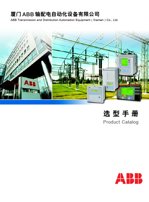
选型手册
Product Catalog
目
录
发布:2005.09.12 状态:新稿 版本:A/2005.09.12 本公司保留数据修改权利·恕不另行通知
1
5
三 端子接线图
*) 功率方向 **) 典型接线 6
外部 跳闸 外部 合闸
隔离开关 Q1 合 隔离开关 Q1 分
隔离开关 Q2 合 隔离开关 Q2 分 隔离开关 Q3 合 隔离开关 Q3 分
REF 542plus 开关柜保护和测控装置
一概述
在中压开关柜的无论有无后台系统各种应用场合中,均能 使用数字式控制技术的解决方案。开关柜保护和测控装置 REF 542plus 就如同它的前一代产品 REF 542,集成了测 量、监视、保护、控制和自检等功能,同时拥有完善的通 讯规约,REF 542plus 能够方便地集成到 ABB 或其他第三 方后台系统中。上述功能和其他一些电能质量检测功能都 基于可编程环境中,新一代装置特别的灵活性和可扩展性 使得一个装置可实现所有的二次方案,甚至传统的方法无 法实现的方案,它都很容易实现。
开关量输入和输出接点数量
输入/输出接点数量 开关量输入接点 跳闸回路监视输出接点
REF 541 15 2
REF 543 25 2
REF 545 34 2
大容量输出接点(NO 单极)
0
大容量输出接点(NO 双极)
5
信号输出接点(NO)
2
2
3
9
11
2
4
信号输出接点(NO/NC)
5
ABB 接触器及热继尺寸

Thermal and Electronic O/L Relays TA 25 DU, TA 42 DU, TA 75 DU, TA 80 DU, TA 110 DU, TA 200 DU, TA 450 DU/SU ...... 9/72 E 16 DU, E 200 DU, E 320 DU, E 500 DU, E 800 DU, E 1250 DU ..................................... 9/74 T 7 DU ...........ቤተ መጻሕፍቲ ባይዱ...................................................................................................................... 9/77
Mini Contactors with Thermal O/L Relays and with Accessories B 6, B 7, BC 6, BC 7 ............................................................................................................ 9/76
Only major dimensions are quoted on the drawings contained in this section. Detailed dimension drawings on request.
abb热过载继电器说明书

abb热过载继电器说明书
ABB热过载继电器是一种用于电气设备保护的重要组件。
它们
通常用于监测电动机的电流,以便在电流超出额定值时断开电路,
以防止电动机过载。
以下是关于ABB热过载继电器的说明书内容:
1. 产品介绍,说明书应该包括ABB热过载继电器的基本介绍,
包括产品型号、尺寸、额定电流范围、工作原理等内容。
它还应该
介绍产品的外观特征和安装方式。
2. 技术规格,说明书中应包括ABB热过载继电器的技术规格,
如额定电流、额定电压、动作特性、环境条件等。
这些规格对于用
户选择合适的继电器至关重要。
3. 安装和连接,说明书应该提供清晰的安装指导,包括继电器
的安装位置、连接方式、接线图等。
此外,还应包括安全注意事项
和安装过程中需要遵守的标准和规定。
4. 使用说明,说明书中应该包括ABB热过载继电器的使用说明,包括如何设置动作电流、如何进行故障诊断和维护等内容。
用户需
要清楚了解如何正确地使用和维护继电器。
5. 故障排除,说明书应该包括常见故障的排除方法和维修指导,以帮助用户在继电器出现故障时快速解决问题。
6. 安全注意事项,最后,说明书应该包括关于继电器安全使用
的注意事项,以及在维修和更换继电器时需要遵守的安全规定。
总的来说,ABB热过载继电器的说明书应该全面介绍产品的技
术参数、安装使用方法、维护保养和安全注意事项,以帮助用户正确、安全地使用这一重要的电气设备保护组件。
ABB CM-PFS 三相监控继电器 产品说明书
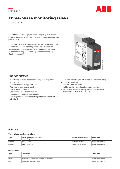
Three-phase monitoring relays CM-PFSThe CM-PFS is a three-phase monitoring relay that is used to monitor three phase mains for incorrect phase sequence and phase failure.All devices are available with two different terminal versions. You can choose between the proven screw connection technology (double-chamber cage connection terminals) and the completely tool-free Easy Connect Technology (Push-in terminals)Characteristics• Monitoring of three-phase mains for phase sequence and failure• Suitable for railway applications • Powered by the measuring circuit • Closed-circuit principle• Screw connection technology or Easy Connect Technology available• Housing material for highest fire protection classification UL 94 V-02C D C 251 014 V 0012• Tool-free mounting on DIN rail as well as demounting • 2 c/o (SPDT) contacts • 22.5 mm (0.89 in) width• 2 LEDs for the indication of operational states• Various certifications and approvals (see overview,document no. 2CDC112246D0201)—Order dataThree-phase monitoring relaysType Rated control supply voltage = measuring voltage Connection technology Order code CM-PFS.P 3 x 200-500 V AC Push-in terminals 1SVR740824R9300CM-PFS.S3 x 200-500 V ACScrew type terminals1SVR730824R9300AccessoriesType DescriptionOrder code ADP.01Adapter for screw mounting1SVR430029R0100MAR.01Marker label for devices without DIP switches 1SVR366017R0100COV.11Sealable transparent cover1SVR730005R0100—DATA S H EE T2DATA SHEET CM-PFSPush-in terminals• Tool-free connection of rigid and flexible wires with wire end ferrule• Easy connection of flexible wires without wire end ferrule by opening the terminals • No retightening necessary• One operation lever for opening both connection terminals • For triggering the lever and disconnecting of wires you can use the same tool (Screwdriver according to DIN ISO 2380-1 Form A 0.8 x 4 mm (0.0315 x 0.157 in), DIN ISO 8764-1 PZ1 ø 4.5 mm (0.177 in))• Constant spring force on terminal point independent of the applied wire type, wire size or ambient conditions (e. g. vibrations or temperature changes)• Opening for testing the electrical contacting • Gas-tightDouble-chamber cage connection terminals • Terminal spaces for different wire sizes• One screw for opening and closing of both cages • Pozidrive screws for pan- or crosshead screwdrivers according to DIN ISO 2380-1 Form A 0.8 x 4 mm(0.0315 x 0.157 in), DIN ISO 8764-1 PZ1 ø 4.5 mm (0.177 in)Both the Easy Connect Technology with push-in terminals and screw connection technology with double-chamber cageconnection terminals have the same connection geometry as well as terminal position.2C D C 253 025 F 00112C D C 253 026 F 0011—Connection technologyMaintenance free Easy Connect Technology with push-in terminalsType designation CM-xxS.yyPApproved screw connection technology with double-chamber cage connection terminals Type designation CM-xxS.yySDATA SHEET CM-PFS3—FunctionsOperating controlsApplicationThe CM-PFS is used to monitor three-phase mains for incorrect phase sequence and phase failure.Operating modeThe three-phase main to be monitored is connected to terminals L1, L2, L3 in accordance to the wiring diagram.The device operates according to the closed-circuit principle g – incorrect phase sequence or phase failure:relays de-energize. The signalling of status indication is made by means of the front-face LEDs.Indication of operational statesR: yellow LED – status indication of the output relays F:red LED – fault messagePhase sequence and phase failure monitoringIf all phases are present with the correct phase sequence, the output relays energize after the start-up delay t s is complete.If a phase failure or a phase sequence error occurs, the output relays de-energize instantaneously.The LED R is on when output relays are energized.In case of motors which continue running with only two phases, the CM-PFS detects phase failure if the reverse fed voltage is less than 60% of the originally applied voltage.21-2221-24L1, L2, L311-1211-14F: red LED R: yellow LEDMeasured valuet s = start-up delay fixed 500 ms2C D C 252 003 F 0212—Electrical connectionL1L22428212522261418L3L3111512161418222624282125L2L1121611151S V C 110 000 F 0118L1, L2, L3Control supply voltage = measuring voltage1115-1216/14182125-2226/2428Output contacts - closed-circuit principle —Connection diagramData at T a = 25 °C and rated values, unless otherwise indicated—Input circuitsType CM-PFSSupply circuit = measuring circuit L1, L2, L3Rated control supply voltage U s = measuring voltage 3 x 200-500 V ACRated control supply voltage U s tolerance-15...+10 %Rated frequency50/60 HzFrequency range45-65 HzTypical current / power consumption400 V AC16 mA / 11 VAMeasuring circuit L1, L2, L3Monitoring functions Phase failure JPhase sequence JMeasuring ranges 3 x 200-500 V ACThreshold value for phase failure U min0.6 x U NHysteresis related to the threshold value-Response time500 msTiming circuitStart-up delay t s fixed 500 ms—User interfaceIndication of operational statesRelay status R1, R2R: yellow LED V output relay energized Fault message F: red LED V Phase failureW Phase sequence error—Output circuitsKind of output11(15)-12(16)/14(18)relay, 1st c/o (SPDT) contact21(25)-22(26)/24(28)relay, 2nd c/o (SPDT) contact1 x2 c/o (SPDT) contacts Operating principle closed-circuit principle 1) Contact material AgNi alloy, Cd freeRated operational voltage U e250 V ACMinimum switching voltage / Minimum switching current24 V / 10 mAMaximum switching voltage / Maximum switching current see "Load limit curves" on page 7Rated operational voltage U e and rated operational current I eAC-12 (resistive) at 230 V 4 A AC-15 (inductive) at 230 V 3 A DC-12 (resistive) at 24 V 4 A DC-13 (inductive) at 24 V 2 AAC rating (UL 508)utilization category(Control Circuit Rating Code)B 300 pilot duty;general purpose 250 V, 4 A, cos phi 0.75 max. rated operational voltage300 V ACmax. continuous thermal current at B 300 5 Amax. making/breaking apparent power at B 3003600/360 VAMechanical lifetime30 x 106 switching cycles Electrical lifetime AC-12, 230 V, 4 A0.1 x 106 switching cyclesMaximum fuse rating to achieve short-circuit protection n/c contact 6 A fast-acting n/o contact10 A fast-actingConventional thermal current I th 4 A1) Closed-circuit principle: output relays de-energize if the measured value exeeds/drops below the threshold.—General dataMTBF on requestDuty cycle100 %Dimensions see ‘Dimensional drawings’Weight Screw connection technology Easy Connect Technology (push-in)net0.128 kg (0.282 lb)0.120 kg (0.265 lb)Mounting DIN rail (IEC/EN 60715), snap-on mounting without any toolMounting position anyMinimum distance to other units vertical / horizontal≥ 10 mm (0.39 in) in case of continuous measuring voltage > 440 V Degree of protection housing IP50terminals IP20—Electrical connection—Environmental dataAmbient temperature ranges operation -25...+60 °Cstorage-40...+85 °Ctransport-40...+85 °CClimatic class IEC/EN 60721-3-33K3Damp heat, cyclic IEC/EN 60068-2-30 6 x 24 h cycle, 55 °C, 95 % RHVibration, sinusoidal IEC/EN 60255-21-1Class 2Shock IEC/EN 60255-21-2Class 2—Isolation dataRated insulation voltage U i input circuit / output circuit600 Voutput circuit 1 / output circuit 2300 VRated impulse withstand voltage U impinput circuit / output circuit 6 kV output circuit 1 / output circuit 2 4 kVBasic insulation input circuit / output circuit600 V ACPollution degree 3Overvoltage category III—Standards / DirectivesStandards IEC/EN 60947-5-1, IEC/EN 60255-27, EN 50178 Low Voltage Directive2014/35/EUEMC Directive2014/30/EURoHS Directive2011/65/EU—Railway application standardsEN 50155, IEC 60571“Railway applications – Electronic equipment used on rolling stock”temperature class T3supply voltage category S1, S2, C1*), C2*)IEC/EN 61373“Railway applications – Rolling stock equipment – Shock and vibration tests”Category 1, Class BEN 45545-2 Railway applications – Fire protection on railway vehicles – part 2:Requirements for fire behavior of materialsHL3and components ISO 4589-2LOI 32.3 %NF X-70-100-1 C.I.T. (T12) 0.45EN ISO 5659-2Ds max (T10.03) 104NF F 16-101: Rolling stock. Fire behaviour. Materials choosingNF F 16-102: Railway rolling stock. Fire behaviour. Materials choosing, applicationfor electric equipmentI2 / F2DIN 5510-2 Preventive fire protection in railway vehicles. Part 2: Fire behaviour andfire side effects of materials and partsfullfilled*) only applicable for devices with DC supply—Electromagnetic compatibilityInterference immunity to IEC/EN 61000-6-2electrostatic discharge IEC/EN 61000-4-2Level 3, 6 kV / 8 kVradiated, radio-frequency,electromagnetic fieldIEC/EN 61000-4-3Level 3, 10 V/m (1 GHz) / 3 V/m (2 GHz) / 1 V/m (2.7 GHz) electrical fast transient / burst IEC/EN 61000-4-4Level 3, 2 kV / 5 kHzsurge IEC/EN 61000-4-5Level 3, 2 kV L-Lconducted disturbances, induced byradio-frequency fieldsIEC/EN 61000-4-6Level 3, 10 Vvoltage dips, short interruptionsand voltage variationsIEC/EN 61000-4-11Class 3harmonics and interharmonics IEC/EN 61000-4-13Class 3Interference emission IEC/EN 61000-6-3high-frequency radiated IEC/CISPR 22, EN 55022Class Bhigh-frequency conducted IEC/CISPR 22, EN 55022Class BLoad limit curves2C D C 252 194 F 0205—AC load (resistive)2C D C 252 193 F 0205—DC load (resistive)2C D C 252 192 F 0205—Derating factor F for inductive AC loadSwitching current [A]S w i t c h i n g c y c l e s2C D C 252 148 F 0206—Contact lifetimein mm and inches2C D C 252 009 F 0011—Accessoriesin mm and inches2C D C 252 010 F 00112C D C 252 008 F 00102C D C 252 186 F 0005—ADP.01 - Adapter for screw mounting—MAR.01 - Marker label —COV.11 - Sealable transparent coverFurther documentationDocument titleDocument type Document number Electronic relays and controls Catalog2CDC 110 004 C02xx CM-PAS, CM-PFS, CM-PSS, CM-PVSInstruction manual1SVC 630 510 M0000You can find the documentation on the internet at /lowvoltage-> Automation, control and protection -> Electronic relays and controls -> Measuring and monitoring relays.CAD system filesYou can find the CAD files for CAD systems at -> Low Voltage Products & Systems -> Control Products -> Electronic Relays and Controls.—We reserve the right to make technical changes or modify the contents of this document without prior notice. With regard to purchase orders, the agreed particulars shall prevail. ABB Ltd. does not accept any responsibility whatsoever for potential errors or possible lack of information in this document.We reserve all rights in this document and in the subject matter and illustrations contained therein. Any reproduction, disclosure to third parties or utilization of its contents – in whole or in parts – is forbidden without prior written consent of ABB Ltd. Copyright© 2020 ABB Ltd.All rights reserved/lowvoltage—ABB STOTZ-KONTAKT GmbH Eppelheimer Strasse 8269123 Heidelberg, Germany2C D C 112192D 0201 R e v . G (01/2020)。
ABB低压继电器手册
2CDC 293 034 F0004
ᕃ ᕄ ᕆ ᕅ ᕇ
1 c/o contact: 250 V, 16 A CR-P012DC1 CR-P024DC1 CR-P048DC1 CR-P110DC1 CR-P024AC1 CR-P048AC1 CR-P110AC1 CR-P120AC1 CR-P230AC1 CR-P012DC2 CR-P024DC2 CR-P048DC2 CR-P110DC2 CR-P024AC2 CR-P048AC2 CR-P110AC2 CR-P120AC2 CR-P230AC2 12 V DC 24 V DC 48 V DC 110 V DC 24 V AC 48 V AC 110 V AC 120 V AC 230 V AC 12 V DC 24 V DC 48 V DC 110 V DC 24 V AC 48 V AC 110 V AC 120 V AC 230 V AC 1SVR 405 600 R4000 1SVR 405 600 R1000 1SVR 405 600 R6000 1SVR 405 600 R8000 1SVR 405 600 R0000 1SVR 405 600 R5000 1SVR 405 600 R7000 1SVR 405 600 R2000 1SVR 405 600 R3000 1SVR 405 601 R4000 1SVR 405 601 R1000 1SVR 405 601 R6000 1SVR 405 601 R8000 1SVR 405 601 R0000 1SVR 405 601 R5000 1SVR 405 601 R7000 1SVR 405 601 R2000 1SVR 405 601 R3000 10 10 10 10 10 10 10 10 10 10 10 10 10 10 10 10 10 10
abb继电器cm-pfs(ABBrelaycm-pfs)
abb继电器cm-pfs(ABB relay cm-pfs)Company name: Fuzhou Intime Automation Technology Co., Ltd. Guangzhou OfficeContact: Zeng WeiMobile:138****9790Business QQ:1165017082E-mail:138****************Company website: Address: Guangdong province Guangzhou Tianhe Zhongshan Avenue Zhongche Po Garden No. 116 building 1008 room BFirst class agent: Admiralty, Muller, ABB, SIEMENS, Wade Miller series;Brand advantage: Schneider 140PLC, Schneider ATS, Q soft start; MITSUBISHI A series, MITSUBISHI FX1S, 1N PLC, MITSUBISHI PLC series high power inverter; weinview touch screen; SICK switch, close to sensors; IFM IFM sensor; OMRON C200H, C2000, C500, CJ1W, CQM and other large PLC; Fuji inverter.CM-PFS, CM-PVS, CM-PSS, CM-PASElectronic time relay - CT seriesModelType CT-EMulti-functionCT-MKECT-MFEEnergization delayCT-ERECT-ERECT-ERECT-EREPower down delay with auxiliary power CT-AHECT-AHECT-AHECT-AHECT-AHECT-AHEPower off delay without auxiliary power supplyCT-ARECT-AREEnergization pulse delayCT-VWECT-VWECT-VWEPower off pulse delay without auxiliary power supply CT-AWECT-AWECT-AWECT-AWECT-AWECT-AWECT-AWECT-AWEEnergization flickerCT-EBEStar delta transformation CT-YDECT-YDECT-YDECT-SDECT-SDESwitch relayCT-IRECT-IREEnergization delayCT-EKECT-EKECT-EKEOff-delay Operation CT-AKECT-AKECT-AKEType CT-SMulti-functionCT-MFSCT-MVSCT-MBSCT-MBSCT-MBSCT-MBSCT-MBSCT-MBSEnergization delayCT-ERSCT-ERSCT-ERSCT-ERSCT-ERSCT-ERSCT-ERSPower down delay with auxiliary power CT-AHSCT-AHSCT-ARSCT-ARSEnergization pulse delayCT-VWSCT-VWSCT-AWSCT-AWSEnergization flickerCT-EBSCT-EBSPulse generatorCT-TGSThrough and off time delay CT-EASCT-EASCT-EVSStar delta transformation CT-YDAVCT-YDAVCT-YDEWSingle pulse generatorCT-PGSType CT-DMulti-functionCT-MFDPower down delay with auxiliary powerCT-AHDEnergization delayCT-ERDEnergization pulse delayCT-VWDEnergization flickerCT-EBDPulse generatorCT-TGDElectronic measuring and monitoring relays - CM seriesModelSingle-phase current monitor CM-SRSCM-SRSCM-SRNCM-SRNCM-SRNCM-SRNCM-SRNCM-SRNCM-SRNCM-SRNSingle-phase voltage monitor CM-ESSCM-ESSCM-ESSCM-ESS CM-ESS CM-ESS CM-ESN CM-ESN CM-ESN CM-ESN CM-ESN CM-ESN CM-ESN CM-ESN CM-ESN CM-ESN CM-ESN CM-ESNCM-EFNThree-phase monitorCM-PBECM-PBECM-PVECM-PVECM-PFECM-PFSCM-PASCM-PSSCM-PVSCM-MPSCM-MPSThermistor PTC motor protection relay CM-MSECM-MSECM-MSS (5)CM-MSS (6)CM-MSS (3)CM-MSS (3)CM-MSS (3)CM-MSS (4)CM-MSS (7)CM-MSS (1)CM-MSS (1)CM-MSS (2)CM-MSS (2)CM-MSS (2) Insulation monitor CM-IWN-DCCM-IWN-ACCM-IWN-ACMotor load monitor CM-LWNCM-LWNCM-LWNCM-LWNCM-LWNCM-LWNCM-LWNCM-LWNLevel monitorCM-ENE MINCM-ENE MAXCM-ENSCM-ENS up/downCM-ENN up/downTemperature monitoring relay - C510 seriesModelOver temperature monitoring with 1 adjustment thresholdsC510.01-24C510.02-24C510.03-24Under temperature monitoring, 1 adjustment thresholdsC510.11-24 24C510.12-24 24C510.13-24 24Over temperature monitoring, 2 adjustment thresholds (1 alarm, 1 off)C511.01-24 24C511.01-W 24C511.02-24 24C511.02-W 24C511.03-24 24C511.03-W 24Under temperature monitoring, 2 adjustment thresholds (1 alarm, 1 off)C511.11-24 24C511.11-W 24C511.12-24 24C511.12-W 24C511.13-24 24C511.13-W 24Digital over / under temperature monitorC512-WC513-WSwitching power supply - CP seriesModelType CP-E CP-E 24/0.75 CP-E 24/1.25 CP-E 24/2.5 CP-E 5/3.0 CP-E 12/2.5 CP-E 48/0.62 CP-E 48/1.25 Type CP-S/C CP-S 24/5.0 CP-S 24/10.0 CP-S 24/20.0 CP-C 24/5.0 CP-C 24/10.0 CP-C 24/20.0EnclosureCP-RUDCP-A RUCP-C MMCP-A CMAnalog signal converter - CC series ModelCC-U/STDCC-U/RTDCC-U/TCCC-U/ICC-U/VCC-U/STDRCC-U/RTDRCC-U/TCRCC-E/STD, V/I / V/ICC-E V/V CC-E V/I CC-E V/I CC-E I/V CC-E I/I CC-E I/I CC-E I/V CC-E I/I CC-E I/I CC-E V/V CC-E/RTD CC-E RTD/V CC-E RTD/I CC-E RTD/I CC-E RTD/VCC-E RTD/ICC-E RTD/ICC-E RTD/VCC-E RTD/ICC-E RTD/ICC-E RTD/VCC-E RTD/ICC-E RTD/ICC-E/TC, J/K / V/I CC-E TC/VCC-E TC/ICC-E TC/VCC-E TC/ICC-E/ICC-E Iac/VCC-E Iac/ICC-E Idc/VCC-E Idc/ICC-E Iac/ILPOCC-E I/I-1CC-E I/I-2Plug in type interface relay - CR series ModelRelay CR-PCR-P024DC1CR-P230AC1CR-P110AC1CR-P110DC1CR-P024AC2CR-P024DC2CR-P048DC2CR-P230AC2 CR-P110AC2 CR-P110DC2 Relay CR-M CR-M024AC2 CR-M024AC2L CR-M024DC2 CR-M024DC2L CR-M230AC2 CR-M230AC2L CR-M110AC2 CR-M110AC2L CR-M110DC2 CR-M110DC2L CR-M220DC2 CR-M220DC2LCR-M024AC3 CR-M024AC3L CR-M024DC3 CR-M024DC3L CR-M230AC3 CR-M230AC3L CR-M110AC3 CR-M110AC3L CR-M110DC3 CR-M110DC3L CR-M220DC3 CR-M220DC3L CR-M024AC4 CR-M024AC4L CR-M024DC4CR-M024DC4L CR-M230AC4 CR-M230AC4L CR-M110AC4 CR-M110AC4L CR-M110DC4 CR-M110DC4L CR-M220DC4 CR-M220DC4L Relay CR-U CR-U024AC2 CR-U024AC2L CR-U024DC2 CR-U024DC2L CR-U230AC2 CR-U230AC2LCR-U110AC2 CR-U110AC2L CR-U110DC2 CR-U110DC2L CR-U220DC2 CR-U220DC2L CR-U024AC3 CR-U024AC3L CR-U024DC3 CR-U024DC3L CR-U230AC3 CR-U230AC3L CR-U110AC3 CR-U110AC3L CR-U110DC3CR-U110DC3LCR-U220DC3CR-U220DC3LRelay accessories - baseCR-PLSCR-PSSCR-M2SSCR-M2LSCR-M3SSCR-M3LSCR-M4SSCR-M4LSCR-U3SCR-U3ECR-U2SRelay accessories - plug and play protection moduleCR-P/M 22CR-P/M 42CR-P/M 92CR-P/M 52CCR-P/M 62CCR-P/M 92CCR-U 21CR-U 41CR-U 91Relay accessories - fixed clamp CR-PHCR-MHCR-MH1CR-UH。
ABB REF610馈线保护继电器 说明书
用户指南
2
特点
REF 610 馈 线 保 护 继 电 器
发布:2004.9.22 版本:B2/2006.02.02 本公司保留数据修改权利,恕不另行通知
● 定时限或反时限特性的过电流保护 ● 定时限或瞬时特性的限时电流速断保护 ● 定时限或瞬时特性的电流速断保护 ● 定时限,反时限或瞬时特性的零序电流Ⅱ段
● RI 型反时限曲线特性下
动作值精度 ● 0.3...0.5 × In
● 0.5...5.0 × In ● 5.0...35.0 × In
0.05...1.00 甚反时限 极反时限 次反时限 一般反时限 1...15 50 ms 2) 30 ms 0.05...2.50 s 0.96
50 ms 30 ms
● RI 型反时限曲线特性下 动作值精度 ● 1.0...10.0% In ● 10.0...100% In ● 100...400% In
0.05...1.00 甚反时限 极反时限 次反时限 一般反时限 1...15 50 ms 2) 30 ms 0.05...2.50 s 0.96
50 ms 30 ms
Ur=110/125/220/250 V dc
Ur=24/48/60 V dc
85...110% × Ur (ac)
80...120% × Ur
80...120% × Ur (dc)
<9 W/13 W
最大值:直流电压额定值的 12%
<50 ms,在额定 Uaux 下 <350 ms
+100℃
T2A / 250 V
1.0...100% In 1.0...40% In 1) 60 ms
ABB中间继电器
2CDC 291 005 S0011
2CDC 2912 011CDS0014C 291 011 S0014
附件 - 功能模块
型号
额定控制电压 Us
二极管 - 反极性保护/续流二极管
CR-P/M 22
6-220 V DC
二极管和LED - 反极性保护/续流二极管
CR-P/M 42
6-24 V DC
CR-P/M 42V 6-24 V DC
1SVR405631R4100
CR-MX024DC2L
24 V DC
1SVR405631R1100
CR-MX048DC2L
48 V DC
1SVR405631R6100
CR-MX110DC2L
110 V DC
1SVR405631R8100
CR-MX024AC2L
24 V AC
1SVR405631R0100
释放电压
1.2 V DC 2.4 V DC 4.8 V DC 11 V DC 7.2 V AC 36 V AC 72 V AC
CR-MX...2 11-12/14 41-42/44
额定功率
0.9 W 0.9 W 0.9 W 0.9 W 1.2 VA 1.4 VA 1.8 VA
触点数量
触点材料 额定工作电压Ue(IEC/EN 60947 - 1) 最小开关电压 最大开关电压 最小开关电流 额定自由空气发热电流Ith 额定工作电流(IEC/EN 60947-5-1) AC等级(UL508;NEMA ICS-5) DC等级(UL508;NEMA ICS-5) 最小开关功率 最大开关(释放)功率 接触电阻 最大工作频率
1SVR405656R0000 10 1SVR405656R1000 10 1SVR405656R2000 10
ABB塑壳断路器具有8种型号
ABB塑壳断路器具有8种型号:T1, T2, T3, T4, T5, T6, T7和S8。
额定极限短路分断能力(380/415V AC)从16kA到200kA。
可提供以下类型的断路器,广泛应用于各种应用场合 :∙应用于交流和直流配电的断路器∙电动机保护用断路器∙应用于交流和直流1000V的断路器∙隔离开关每个断路器都具有3极和4极,可配完整系列的保护脱扣器:热磁脱扣器、单磁脱扣器和电子脱扣器。
配有TMD和TMA热磁脱扣器的T1, T2, T3, T4, T5和T6可用于直流电厂,额定电流从1A到800A,最小工作电压为24VDC。
配电用的断路器ABB塑壳断路器Tmax和Isomax额定工作电流从1A到3200A,具有固定式、插入式和抽出式,3极和4极。
Tmax T1具有单极型断路器T1B 1p,分断能力为25 kA (220/230 V AC)。
脱扣器可互换Tmax T4,T5和T6可安装热磁脱扣器、单磁脱扣器和电子脱扣器。
由于安装非常简单,根据实际需求,客户可非常简单的更换这些脱扣器。
当然,此时客户需要对安装负责。
这些脱扣器可互相更换,使得断路器使用不仅灵活,而且节约空间和减少库存。
符合标准塑壳断路器及其附件均符合国际IEC 60947-2标准及EC的相关指令,包括低压指令(LVD) no. 73/ 23 EEC” 和“电磁兼容指令(EMC) 89/336 EEC”.ABB质量体系符合ISO 9001标准和欧洲EN ISO 9001和意大利UNI EN ISO 9001标准。
此产品符合船用电气设备的规定,已获得主要船级社的认可(如RINA - QUACER)等:T1 1p T1T2T3T4T5T6S7S8额定不间断电流 Iu [A] 160 160 160 250 250320400630630800100012501600200025003200极数No. 1 3-4 3-4 3-4 3-4 3-4 3-4 3-4 3-4额定工作电压Ue AC 50-60Hz[V] 240 690 690 690 690 690 690 690 690额定工作电压Ue DC[V] 125 500 500 500 750 750 750 - -额定冲击耐受电压 Uimp [kV] 8 8 8 8 8 8 8 8 8额定绝缘电压 Ui [V] 500 800 800 800 1000 1000 1000 1000 1000 测试电压 (50 Hz, 1分钟) [kV] 3 3 3 3 3.5 3.5 3.5 3 3分断能力额定极限短路分断能力IcuAC 50-60 Hz 380/415 V [kA] 25(1)(2)16 36 36 85 36 50 3620036 20036 10050 10085 120额定极限短路分断能力Icu AC 50-60 Hz 690 V [kA] 3 66 10 5 820 8020 8020 15020 3540 50额定极限短路分断能力IcuDC 500 V - 3 极串联 [kA] 25(3)16 36 36 85 36 50 167016 7020 65--额定运行短路分断能力 Ics AC 50-60 Hz 380/415 V [kA] 18 16 25 36 70 27 36 20036 20035 1505047 60使用类别 (IEC 60947-2) AAAAAB/ABBB机械寿命 N. op x [103] No 25 25 25 25 20 20 20 10 10电气寿命 ( 415 V)N. op x [103] No 88888 6 75 7 5 7 5 2.5 1.5脱扣保护*TMF (T不可X调, M不可调)X X XTMD (T可调, M不可调)X X X XTMA (T可调, M可调)TMG (T可调, MX X可调)ELT (电子式) X X X X X X 基本尺寸 (固定式)宽度 1 极[mm] 25.4宽度 3 极[mm] 76 90 105 105 140 210 210 406 宽度 4 极[mm] 102 120 140 140 184 280 280 556 深度[mm] 70 70 70 70 103.5 103.5 103.5 138.5 242406 400 高度[mm] 130 130 130 150 205 205 268406接线端子形式固定式 F F F F F F F F F 插入式P P P P抽出式W W W W(1) In=16 A 和 In= 20 A Icu= 16 k A(2) Icu 在 230 V AC(3) Icu 在 125 V DC*脱扣单元:TMF = 热磁固定脱扣TMD = 热磁式 (带T可调)TMA = 热磁式 (带T可调, M可调)TMG = 发电机保护脱扣 (带T可调, M不可调)ELT = 电子式电动机保护用断路器起动, 切换和三相异步电动机的保护是基本操作的正确使用, ABB SACE 建议2个不同的方案:∙一个传统系统对抗短路的断路器, 对抗过载, 缺相或相不平衡的热过载继电器, 对抗电动机切换的接触器∙一个集成系统保护, 有赖于 PR222MP 脱扣保护, 确保: 对抗短路, 过载, 对抗缺相或相不平衡和对抗转子锁紧应用6种规格 (T2, T3, T4, T5, S6 和 S7)均可在大范围起动, 由 0.37 kW 高达 250 kW 带 Tmax T5 和355 kW 带 Isomax S6 (400 V AC).标准认可使用于配电断路器.T2T3T4T5T6S7额定不间断电流Iu[A] 160 250 250320400630800 1250额定工作电流In [A] 1÷100 100÷200 80÷250 3204003206301000 极数No. 3 3 3 3 3 3额定工作电压UeAC 50-60Hz,额定工作电压UeAC 50-60Hz[V] 690 690 690 690 690 690额定冲击耐受电压 Uimp[kV] 8 8 8 8 8 8额定绝缘电压Ui [V] 800 800 1000 1000 1000 1000测试电压(50Hz, 1 分钟)[kV] 3 3 3.5 3.5 3.5 3分断能力额定极限短路分断能力Icu AC 50-60 Hz 380/415 V [kA] 36 85 36 5036 20036 20036 10050 65额定极限短路分断能力Icu AC 50-60 Hz 690 V [kA] 6 10 5 8 20 80 20 80 20 30 20 35 额定运行短路分断能力Ics AC 50-60 Hz 380/415 V [kA] 36 702736 20036 20036 7550使用类别 (IEC 60947-2) A A A B/A B B 机械寿命 103[N. op.]25 25 20 20 20 10电气寿命 (415 V) 103[N. op.]8 8 8 7 5 5脱扣器保护 (短路保护)*MF X单磁式MA XX X电子式(PR221 DS-I )X X X电子式 (PR211 I ) X脱扣器保护 (集成保护)*PR222 MPX XPR212 MPX X 基本尺寸 (固定式)宽度[mm] 90 105 105 140 210 210深度[mm] 70 70 103.5 103.5 103.5 138.5高度[mm] 130 150 205 205 268/406 406接线端子形式固定式 F F F F F F插入式P P P P抽出式W W W W*脱扣单元:MF = 电磁固定脱扣MA = 电磁式 (可调)PR221DS-I = 电子式PR211 = 电子式PR222MP = 电子式(适用于电动机保护)PR212MP = 电子式(适用于电动机保护)Circuit-breakers for applications up to 1000 VWithin the panorama of the ABB moulded-case circuit-breakers there is also the range of circuit-breakers for applications in direct current and in alternating current up to 1000 V.The typical sectors of use for these are mining, road and railway tunnel installations, electric traction and industrial applications in general. The circuit-breakers are available in three-pole and four-pole version with TMD or TMA adjustable thermomagnetic releases for use in direct and alternating current, or in version three-pole with electronic releases (Tmax with PR221DS, PR222DS/P; Isomax with PR21x), for applications in alternating current.The dimensions of these circuit-breakers are the same as the standard ones. They can, moreover, be combined with all the accessories available, except for the residual current, and can be converted into the removable or withdrawable version using a conversion kit and fixed parts of the standard circuit-breakers.交流配电ACT4T5T6额定不间断电流Iu [A] 250 400 - 630 630- 1000极数[No.] 3/4 3/4 3分闸能力额定极限短路分断能力Icu AC 50-60 Hz (1000V) [kA] 20 20 20 额定运行短路分断能力Ics AC 50-60 Hz (1000 V) [kA] 20 15 短路合闸能力额定短路合闸能力Icm AC 50-60 Hz ( 1000V) [kA] 40 40 40脱扣保护热磁式 (带T 可调)TMDX热磁式 (带T 可调, M 可调)TMAX X电子式 ELTXXX直流配电 DC T4 T5 T6额定不间断电流Iu [A] 250 400 - 630 630- 800 极数 [No.] 4 4 4 分断能力额定极限短路分断能力Icu DC 1000 V 4 极串联 [kA] 404040脱扣保护TMD (T 可调, M 不可调) XTMA (T 可调, M 可调) X X X两系列的通用值T4T5T6额定工作电压Ue [V] 1000 1000 1000额定冲击耐受电压Uimp [kV] 8 8 8额定绝缘电压Ui [V] 1000 1000 1000隔离功能X X X[V] 3500 3500 3500测试电压(50Hz, 1 分钟)参考标准IEC 60947-2 X X X尺寸 (固定式)宽度 (3 极) [mm] 105 140 210宽度 (4 极) [mm] 140 184 280深度[mm] 103.5 103.5 103.5高度[mm] 205 205 268 / 406接线端子形式固定式 F F F插入式P P抽出式W W W*脱扣单元:TMD =热磁式 (带T可调)TMA = 热磁式 (带T可调, M可调)ELT = 电子式Switch-disconnectorsThe switch-disconnectors derive from the corresponding circuit-breakers, of which they keep the same overall dimensions, the versions, the fixing systems and the possibility of mounting the accessories. This version onlydiffers from the circuit-breakers in the absence of the protection releases. They are characterised by a rated voltage of 690 V in alternating current and up to 750 V in direct current.T1 DT3 DT4 DT5 DT6 DS7 DS8 DIth[A]1602503204006306308001000100012501600200025003200 Ie [A] 125 200 320 4006306308001000100012501600200025003200 极数Nr. 3-4 3-4 3-4 3-4 3-4 3-4 3-4额定工作电压Ue AC50-60Hz[V] 690 690 690 690 690 690 690 额定工作电压Ue DC [V] 500 500 750 750 750 750 750 额定冲击耐受电压Uimp [kV] 8 8 8 8 8 8 8额定绝缘电压Ui [V] 800 800 1000 1000 1000 1000 1000测试电压(50 Hz,1 分钟)[kV] 3 3 3.5 3.5 3.5 3 3额定短路合闸能力Icm [kA] 2.8 5.3 5.3 11 30 52.5 85 Icw [kA] 2 3.6 3.6 6 15 25 40基本尺寸 (固定式)宽度 (3极) [mm] 76 105 105 140 210 210 406 宽度 (4 极) [mm] 102 140 140 184 280 280 556 深度[mm] 70 70 103.5 103.5 103.5 138.5 242高度[mm] 130 150 205 205 268406406 400 接线端子形式固定式 F F F F F F F插入式P P P抽出式W W W(*) W(*) 高达 800 ACircuit-breakers according to UL CSA StandardsIn the field of molded case circuit breakers, conforming to the UL489 and CSA C22.2 Standards, SACE’s proposal presents the following ranges:∙power distribution circuit breakers (fitted with thermomagnetic or electronic trip units)∙power circuit breakers with magnetic only trip units for motor protection (Motor Control Protection - MCP)∙switch-disconnectors for use as isolators or switching devices for lines, busbars or plant parts (Molded Case Switch - MCS).The possibilities are increasingly greater for those customers who also operate on the markets subject to the standards defined by the UL/CSA Standards since they have an entire range of molded case circuit-breakers available, with continuous current ratings which go from 100A to 2500A and interrupting rating, at 480 V AC, which can reach 100kA.As well as extending the field of continuous current ratings downwards, introduction of the T1 size means that the applications typical of power subdistribution where a circuit-breaker characterised by limited overall dimensions, but which guarantees great versatility in mounting accessories and installation, is particularly worthwhile.The smallest of the molded case circuit breakers, the single-pole T1, conforming to the UL, is also presented.Finally, the S8 circuit-breaker according to UL/CSA Standards also allows completion towards the higher continuous rating currents. Isomax S8V 1600, 2000 and 2500 A lend themselves to being installed immediately to the load side of the power supply sources of the low voltage systems and are suitable for operating safely under the most severe service conditions required of modern plants. The high performances, great flexibility of accessories, ease of coordination with the devices located on the load side and the possibility of limiting the depth of the switchgear thanks to the reduced overall dimensions of the circuit breaker make Isomax S8 a particularly advantageous solution.配电 (MCCB)T1T2T3T4T5S6S7S8外框尺寸[A] 100 100 225 250 400600(2)800 1200 160020002500极数No.34234342342342323 3干扰值480 V [kA] 22(1)3565253525150251505010065 100600 V [kA] 105 18851885254250 85500 V DC(3极串联)[kA] 25 25100251003565600 V DC(3 极串联)[kA] 3.6 166516652050脱扣单元*TMD, TMA X X X X X XELT X X X X X X电动机保护(MCP)T1T2T3T4T5S6S7S8外框尺寸[A] 100 225 250 400 800 1200 160020002500 额定值[A] 10÷100100÷20010015025030040060080010001200160020002500极数 No. 3 3 3 3 3 3 3 干扰值240 V [kA] 65 150 65 65 200 65 200 50 100 65 100 480 V [kA] 35 65 35 25 100 25 100 50 100 65 100 600 V [kA] 18 65 1865脱扣单元* MA X XELT X X X X X X隔离开关 (MCS)T1 T2 T3 T4 T5 S6 S7 S8额定值100 150 225 250 400600(2)8001200 2500极数No. 3-4 3-4 3-4 3-4 3 3 3 超磁 [kA] 1 1.5 2.25 3 5610 20 35额定电压 AC 50-60 Hz [V] 480 480 600 600 600 600 600额定电压 DC [V] 500 500 600 600 600600600通用数值T1 T2 T3 T4 T5 S6 S7 S8 额定电压 AC 50-60Hz [V] 480 480 480 600 600 600 600 600额定电压 DC[V] 500 500 500 600600600--测试电压(50 Hz, 1 分钟)[kV] 3 3 3 3.5 3.5 3 3 3机械寿命103[N. op.]25 25 25 20 20 20 10 10电气寿命(在415 V) 103[N. op.]8 8 8 8 7 / 5 7 / 5 7 / 5 2.5 /1.5尺寸 (固定式)宽度 3 极[mm] 76 90 105 105 140 210 210 406 宽度 4 极[mm] 102 120 140 140 184 280 280 406 深度[mm] 70 70 70 103.5 103.5 103.5 138.5 242高度[mm] 130 130 150 205 205 268406406 400 接线形式固定式 F F F F F F F F 插入式P P P P抽出式W W(1) 18 kA 在 277 V AC 案适用于 T1 1p(2) 如需600 A, 请与ABB办事处联系*脱扣单元:TMD = 热磁式 (带T可调)TMA = 热磁式 (带T可调, M可调)ELT = 电子式。
- 1、下载文档前请自行甄别文档内容的完整性,平台不提供额外的编辑、内容补充、找答案等附加服务。
- 2、"仅部分预览"的文档,不可在线预览部分如存在完整性等问题,可反馈申请退款(可完整预览的文档不适用该条件!)。
- 3、如文档侵犯您的权益,请联系客服反馈,我们会尽快为您处理(人工客服工作时间:9:00-18:30)。
Contact: /contacts R Low Voltage Products and Systems
Docume1 (02/2008)
1.5-15 s ON OFF
2CDC 292 003 F0b06
CR-P/M T1 CR-P/M T2
0.8-8 min
ON OFF ON OFF 1 2
6.4-64 min
A2
A1
Technical data
Type Input circuit - Supply circuit Rated control supply voltage Us Rated control supply voltage tolerance Frequency range Typ. power consumption at 12 V DC at 24 V DC at 12 V AC at 24 V AC Residual ripple at DC Release voltage Timing circuit Timing functions Time ranges CR-P/M T1 CR-P/M T2 15 s 60 s 8 min 64 min Base accuracy Timing error within the rated control supply voltage tolerance Timing error within the temperature range Output circuit depending on the interface relay CR-P or CR-M used Environmental data Temperature range Humidity Climatic category Pollution degree Indication of operational states green LED Operating controls Tolerance of setting Output relay energized IEC 721-3-3 IEC 664-1 operation (IEC 68-1) storage 0...+50 °C -20...+70 °C 20-90 %, no condensation 3K3 2 A ON-delay, CA Impulse-ON 1.5 -15 s 6-60 s 0.8-8 min 6.4-64 min w30 % (of full-scale) w30 % CR-P/M T... A1-A2 12-24 V AC/DC -25...+25 % 50-60 Hz 75 mW 150 mW 100 mW 200 mW 0 9V
A1-A2 Relay LED t t = adjusted time delay <t
Accessories for interface relays CR-P and CR-M Pluggable time modules CR-P/M T...
Data sheet
Connection diagram DIP switch position
Dimensions
in mm
24.5
15.5
11.6 14.7
Further documentation
Document title Sockets CR-P Relays CR-P Sockets CR-M Relays CR-M Document type Data sheet Data sheet Data sheet Data sheet Document number 2CDC 117 004 D0203 2CDC 117 001 D0203 2CDC 117 005 D0203 2CDC 117 002 D0203
2CDC 292 001 F0b07
19
ABB
ABB STOTZ‑KONTAKT GmbH Eppelheimer Strasse 82, 69123 Heidelberg, Germany Postfach 10 16 80, 69006 Heidelberg, Germany Internet /lowvoltage R Control Products
Approvals
� H UL 60950, CAN/CSA C22.2 No 60950
Marks
a CR-P/M T... 1 Potentiometer for the fine adjustment of the desired time 2 green LED V: Output relay energized CE
2CDC 292 005 F0b06
K
6-60 s
ON OFF
Accessories for interface relays CR-P and CR-M Pluggable time modules CR-P/M T...
Data sheet
General data Duty time Repeat accuracy (constant parameters) scale 1.5-15 s scale 6-60 s scale 0.8-8 min scale 6.4-64 min Dimensions (W x H x D) Material of enclosure Degree of protection Mounting Mounting position Standards RoHS directive Conformity Electromagnetic compatibility electrostatic discharge (ESD) electromagnetic field (HF radiation resistance) CEI-EN 61000-6-2 CEI-EN 61000-6-3 2002/95 EC CEI-EN 60730-2-7 IEC 67-1-18a when mounted 100 % w0,2 w0,2 w1 w2 15.5 mm x 24.5 mm x 11.6 mm Pa6 +20% GF, UL 94 V2 IP30 pluggable into sockets CR-PLS, CR-PLC, CR-M2LS, CR-M3LS, CR-M4LS, CR-M4LC any
Operating mode
The CR-P/M T... offer 4 time ranges, adjustable with DIP switches. The fine adjustment of the time delay is made via the thumbwheel on the front of the unit.
A1-A2
CA Impulse-ON (CR-P/M T2) This function requires continuous control supply voltage. The output relay energizes immediately when control supply voltage is applied and de-energizes when the set pulse time is complete. The green LED glows as long as the relay is energized. If control supply voltage is interrupted, the output relay de-energizes and the time delay is reset.
Application
The time modules CR-P/M T... can be plugged into the sockets CR-PLS, CR-PLC, CR-M2LS, CR-M3LS, CR-M4LS and CR-M4LC of the CR-P and CR-M range 2-, 3- or 4-pole pluggable interface relays. This way very compact 2-, 3- or 4-pole time relays with a rated operational current of up to 16 A can be provided.
Function diagrams
A On-delay (CR-P/M T1)
Relay LED t t = adjusted time delay <t 2CDC 292 001 F0206 2CDC 292 002 F0206
Timing begins when control supply voltage is applied. When the selected time delay is complete, the output relay energizes and the green LED glows. If control supply voltage is interrupted, the output relay de-energizes, the time delay is reset and the green LED turns off.
As part of the on‑going product improvement, ABB reserves the right to modify the characteristics of the products described in this document. The information given is non‑contractual. For further details please contact (/contacts) the ABB company marketing these products in your country.