FUSE保险丝讲义教材
保护用fuse选型说明.

1保险丝类1.1保险丝结构介绍一般保险丝由三个部分组成:一是熔体部分,它是保险丝的核心,熔断时起到切断电流的作用,同一类、同一规格保险丝的熔体,材质要相同、几何尺寸要相同、电阻值尽可能地小且要一致,最重要的是熔断特性要一致;二是电极部分,通常有两个,它是熔体与电路联接的重要部件,它必须有良好的导电性,不应产生明显的安装接触电阻;三是支架部分,保险丝的熔体一般都纤细柔软的,支架的作用就是将熔体固定并使三个部分成为刚性的整体便于安装、使用,它必须有良好的机械强度、绝缘性、耐热性和阻燃性,在使用中不应产生断裂、变形、燃烧及短路等现象;电力电路及大功率设备所使用的保险丝,不仅有一般保险丝的三个部分,而且还有灭弧装置,因为这类保险丝所保护的电路不仅工作电流较大,而且当熔体发生熔断时其两端的电压也很高,往往会出现熔体已熔化(熔断)甚至已汽化,但是电流并没有切断,其原因就是在熔断的一瞬间在电压及电流的作用下,保险丝的两电极之间发生拉弧现象。
这个灭弧装置必须有很强的绝缘性与很好的导热性,且呈负电性。
石英砂就是常用的灭弧材料。
参数解释:①.NORMAL OPERATING CURRENT: FUSE所串联回路通过的满载电流②.INTERRUPTING RATING:在保险丝额定电压范围内所允许保险丝安全熔断的电流,目前使用的半导体保护保险的INTERRUPTING RATING一般达到20KA,如果此电流持续时间足够短,Fuse将不会熔断,fuse具有重复承受此冲击的能力。
但是注意,如果短路电流超过此分断电流规格,可能导致FUSE无法正常熔断。
③.VOLTAGE RATING:Fuse所承受的额定电压,如果Fuse熔断后两端的电压差越高,由于内部的拉弧效应,Fuse熔断速度越慢,参考曲线如下:图中K表示I2t的能量系数。
④.TIME-CURRENT CURVE: Fuse 过载能力的查核表,通过电流/时间曲线可以找出fuse在不同电流模式下的过载时间,所有fuse均有此曲线,下图为Ferraz 30A Fuse 的TIME-CURRENT CURVE曲线供参考。
保险丝(Fuse)

保险丝(Fuse)What is the working principle of a fuse?As we all know, when the current flows through the conductor, there is a certain resistance in the conductor, so the conductor will be heated. And heat follow this formula: Q=0.24I2RT; Q is the heat, the 0.24 is a constant, I is the current flowing through the conductor, R is the resistance of a conductor, T is the current through the conductor time; so the formula we can see that the principle of simple fuse.When the material and its shape of the fuse are determined, its resistance R is relatively determined (without considering its resistance temperature coefficient). When the current flows through it, it heats up, and as time goes on, it heats up. The size of the current and the resistance heat generating speed, fuse structure and its installation condition to determine the heat dissipation rate, if the speed is less than the heat generated in the heat dissipation rate, the fuse is not fuse. If the velocity of heat is equal to the speed of heat dissipation, it will not fuse for a considerable period of time. If the speed of heat generation is greater than the speed of heat dissipation, the heat will be more and more. And because it has a specific heat and mass, the increase of its heat is manifested in the rise of temperature, when the temperature rises to the fuse above the melting point, the fuse will fuse. That's how the fuse works. You should know from this principle that you must carefully study the physical properties of the materials you choose when designing and manufacturing fuses, and make sure they have the same geometric size. Because these factors play an important role in the normal operation of the fuse. Also,when you use it, you must install it correctly.The basic working principle of fuse1. structure:In the circuit overcurrent protection device is the most commonly used small tubular fuse, it is made of molten metal with metal connecting terminal ends of tube body and a tube of the two major components, the shell part of the role is to support and join, most of the fuse is a cylindrical shape, which is called tubular the key; function is determined by the internal melt.2. function:The fuse is connected in series, the general requirements of resistance to small (smaller power consumption), so when the circuit is in normal operation, only the equivalent of a fuse wire can be used stably for a long time; because the power supply or external interference and current fluctuations, also overload fuse can withstand a certain range; only when large current overload or short circuit fault - - circuit, the fuse will move, to protect the safety of the circuits by interrupting current.3. principle:Fuse energized by current conversion of heat will make up the temperature of the melt, the normal operating current or load current overload allowed, the current produced by melt and heat,the housing and the surrounding environment from radiation, convection and conduction mode of heat can be gradually reached equilibrium; if the heat can not keep up the pace the heating, the heat will gradually accumulate in the melt, melt temperature rise, once the temperature exceeds the melting point melt will make it melt, thereby cutting off the current, played the role of security protection.4. terms:Rated current: nominal working current of fuse, code name: InRated voltage: nominal working voltage of fuse, code name: UnVoltage drop: the voltage drop at the end of the fuse under rated current. Code: UdCold resistance: the fuse itself does not work when the resistance value, code: RnOverload capacity: the overload current that fuses can work for a long time (some varieties can be under high temperature)Fusing characteristic: the performance index of fuse work -- the function relation between load current and fuse time, that is time / current characteristic (also called ampere second characteristic).There are usually two ways of expression:Fusing characteristic curve: load current is X coordinate, fusetime is Y coordinate,A curve formed by the average fuse time coordinate point of a fuse under different current loads. Each type of fuse has a corresponding curve that can represent its fusing characteristics. This curve can be used as a reference when selecting fuses.Fusing characteristic table: a table consisting of several representative load current values and corresponding fuse time. Each type of fuse has a fuse characteristic table, which can be used to detect the basis of fuse.Breaking capacity: the most important safety indicator of fuses - the maximum current that can be safely broken when a large overload current (short circuit) is applied. Safety breaking is the phenomenon that the fuse breaking circuit is not splashing, burning, explosion and so on, endangering the surrounding components and even personal safety. Code name: IrMelting heat value: the nominal energy value required to fuse the melt of a fuse is a fuseTest conditions for miniature tubular fusesSmall tube fuse test results and test conditions have a great relationship, the most important aspects are as follows:The use of 1. constant current power supplyThe use of constant current power supply power supply ratherthan using the fuse. If used in the evaluation of power supply, load due to the temperature rise will change the current through the fuse, the fuse current change time measured is not accurate.DC constant current power supply must be used when testing fuse fusing characteristicsThe AC power supply should be used when testing the voltage drop of the fuse. The rated current of the load and the reading after thermal balance are obtainedThe AC power supply should be used when testing the rated breaking capacity of the fuse, and the phase selector switch and the safety protection device are neededThe AC power supply should be used when testing the durability of the fuse, and only one interruption is allowed during the whole testThe use of 2. standard test deviceThe test of the fuse characteristics of small tubular fuses must be carried out with specific test devices, including fuses, clamps, the diameter and length of the connecting wires, and the accuracy of the measuring instruments. IEC and UL test fixtures are not the same.The environmental temperature and other conditions of the test room are in accordance with the requirements of safety standards3. voltage drop and cold resistanceGenerally speaking, the cold resistance of the fuse is basically a fixed value, and the voltage drop (thermal resistance) will change with the rise and fall of temperature, so in application, the voltage drop when the rated current is important.The lower the rated current of the fuse resistance greatly. The application conditions of low voltage, voltage drop will play a decisive role, in some extreme cases, testing due to the desired output current (application). The voltage drop and the cold resistance of the fuse can generally be converted to each other.The voltage drop of the fuse is tested by alternating current, and the cold resistance of the fuse can be tested by direct current.4. break capacityFuse breaking capacity test of great power, general manufacturers do not have the appropriate conditions, the company has built a lite testing mechanism is very large, all have the ability to fuse the various test.The current AC sine wave have different values in different phase, the energy will have great difference, and the fuse breaking capacity is in AC rated voltage, so it has a great relationship with the closing phase of the load circuit, IEC test requirements: phase test circuit must be zero voltage in300C after the closing.5. durabilityIEC standard durability test to fuse six samples in series, in the course of the experiment, only one interruption caused by accident permission to continue after the end of continuous interruption to finish the whole test.6. melting heat value and powerThe melting heat value and power of fuse is a reference for selecting fuse, and there is no regulation for testing.Most of the fuse suppliers can't provide this parameter,Only its catalog for almost every kind of fuse is marked with a melting heat energy value parameter, provides a reference for accurate selection of user data integrity.7. pull and torqueTubular fuses are required to withstand the pull of 0.5Kg without the requirement for torque.The method of tensile test is to use the specified special tools.IEC standard will be required to conduct testing for 2 hours after immersion in 150C-350C fuse in the warm water, for the sake of convenience, can also be carried out under normalconditions.8. collimationThe end cap and the tube body of the fuse must be kept on the same axis to ensure the good contact during the connection, and the prescribed collimation gauge shall be used to check the collimation of the fuse9. signsSign small tubular fuse generally at the ends of the copper with hard surface printing, which includes:The end: the manufacturer's trademark, such as LF or LF OVS lite;A variety of security authentication marks, for example:Second terminal: fuse characteristic symbol:F-- stands for fast fusingT-- stands for slow fusingM-- stands for Medium Speed FusesFF-- stands for express fusesTT-- stands for very slow fusingRated current value:More than 1 A is represented by XX ABelow 1 A is represented by XX mATypes of breaking capacity:L-- stands for low disjunctionH-- stands for high resolution classesRated voltage:250 V or 125 VSome fuses also have color ring marks on the shell, or labels inside the tube, so that they can be easily identified in the circuit.Select the ten element of the fuseRated current;Rated voltage;Ambient temperature;Voltage drop / cold resistance;Fusing characteristics: overload capacity,Time / current characteristics;Breaking capacity;Melting heat value;Durability (life);Structural features: shape / size,Installation form;- Security certification.The basic working principle of fuse1. structure:In the circuit overcurrent protection device is the most commonly used small tubular fuse, it is made of molten metal with metal connecting terminal ends of tube body and a tube of the two major components, the shell part of the role is to support and join, most of the fuse is a cylindrical shape, which is called tubular the key; function is determined by the internal melt.2. function:The fuse is connected in series, the general requirements of resistance to small (smaller power consumption), so when thecircuit is in normal operation, only the equivalent of a fuse wire can be used stably for a long time; because the power supply or external interference and current fluctuations, also overload fuse can withstand a certain range; only when large current overload or short circuit fault - - circuit, the fuse will move, to protect the safety of the circuits by interrupting current.3. principle:When the fuse is energized, the heat of the current will increase the temperature of the melt. When the load is normal or the overload current is allowed, the heat produced by the current passes through the melt,The housing and the surrounding environment from radiation, convection and conduction mode of heat can be gradually reached equilibrium; if the heat can not keep up the pace of heating, the heat will gradually accumulate in the melt, melt temperature rise, once the temperature exceeds the melting point melt will make it melt, thus interrupting current. Play the role of security protection.4. terms:Rated current: nominal working current of fuse, code name: InRated voltage: nominal working voltage of fuse, code name: UnVoltage drop: the voltage drop at the end of the fuse under rated current. Code: UdCold resistance: the fuse itself does not work when the resistance value, code: RnOverload capacity: the overload current that fuses can work for a long time (some varieties can be under high temperature)Fusing characteristic: the performance index of fuse work -- the function relation between load current and fuse time, that is time / current characteristic (also called ampere second characteristic).There are usually two ways of expression:Fusing characteristic curve: the curve whose load current is X coordinate, fuse time is Y coordinate, and the fuse fuse time coordinate point under different current load. Each type of fuse has a corresponding curve that can represent its fusing characteristics. This curve can be used as a reference when selecting fuses.Fusing characteristic table: a table consisting of several representative load current values and corresponding fuse time. Each type of fuse has a fuse characteristic table, which can be used to detect the basis of fuse.Breaking capacity: the most important safety indicator of fuses - the maximum current that can be safely broken when a large overload current (short circuit) is applied. Safety breaking is the phenomenon that the fuse breaking circuit is not splashing, burning, explosion and so on, endangering thesurrounding components and even personal safety. Code name: IrMelting heat value: the nominal energy value required to fuse the melt of a fuse is a fuseFuse standardThe fuse rated value and other performance indicators is according to the standard experimental conditions and acceptance of determination. Acceptance is determined by one or more of the fuse is an important standard. The standard, in order to correctly choose to fuse circuit protection.United States UL and Canada CSA248.14 auxiliary overcurrent protection fuse (maximum 600 Volts) (formerly known as UL198G and CSA C22.2, No.59)UL classificationThe fuses of UL meet the requirements of the UL/CSA248.14 standard. Here are some requirementsUL ampere rating is tested at 110%, 135% and 200% of the rated current. The fuse must carry current of its rated value of 110% and must be stable at a temperature rise of no more than 75 degrees centigrade.The fuse must be broken within 30 hours at rated current of 135%, and must be cut off within two minutes at rated current of 200%. The rated value is between 35 and 60 amperes and is disconnected within 4 minutes.The fusing capacity of UL classification fuses is 10000 amperes AC at the rated voltage of 125V. A fuse class with a rated voltage of 250 volts fuses at 125 volts and has a rated capacity of 10000 amperes, while at least 250 volts has the minimum fusing rating given below.Fuse ampere ratingRated capacity of fuse (An Pei)Voltage ratingFrom 0 to 13Thirty-five250VAC1.1 - 3.5One hundred250VAC3.6 - 10Two hundred250VAC10.1 - 15Seven hundred and fifty250VAC15.1 - 30One thousand and five hundred250VACAccording to the American Underwriters Laboratory UL component outline approval (UR)The UL certification program is different from the UL classification. UL will detect fuses according to the specifications required by the manufacturer. If the fuse is designed for a specific purpose, then the measuring points may be different from the UL classification requirements. For the fuse approved by the component outline, the UL requires the application of the identification book.UL275 glass fuse for automobiles (32 volts)UL classificationUL ampere rating test is carried out under rated current of 110%, 135% and 200%. The rated capacity test is not required.CSA certificateThe Canadian CSA certificate is similar to the American UL classification, and its component outline is also similar to that of UR in the United states. The outline of this component is convenient for manufacturers to make specifications, and then test results are checked by CSA.MITI appraisal bookThe MITI Certificate in Japan is similar to the UL classification in the United states.International Electrotechnical Commission (IEC)Publications 127, first, second, third, five (250 volts)The IEC organization is different from the UL in the United States and the Canadian CSA, because IEC only makes rules and does not issue testimonials.UL and CSA develop procedures, and are responsible for testing and issuing certification. The IEC certification is issued by SEMKO (Swedish Institute of electrical equipment testing and identification) and BSI (British Institute of standards) and UL and CSA.IEC publication 127 defines two breaking level (fuse rated capacity). Low capacity fuse must pass ten times or 35 Amperes or even higher rated current of the current test. H.b.c. fuses must pass through ten times the rated current of 35 Amperes or even higher current. High breaking capacity of the fuse mustpass 1500 ampere current test.The first page -F type quick action, high breaking abilitySecond page -F type quick action, low breaking abilityThird page -T type delay, low breaking capacityFourth page -T delay, high breaking capabilityThe letters "F" and "T" represent the time current characteristics of type F and type T fuses. One of the "F" and "T" will be marked on the end caps of the fuseFuse break time of IEC127 and UL/CSA248-14:Rated ratio 100UL standard 248-14IEC F, the first page and the second pageIEC T type third pagesIEC T type fifth pages110%4 hours minimum---135%60 minutes Max---150%-Minimum 60 minutes Minimum 60 minutes Minimum 60 minutes 200%2 minutes Max--210%-30 minutes Max2 minutes Max30 minutes MaxIEC and in 275%, 400% and 1000% of the rated value of test requirements, but this table is used to indicate according to different specifications but has the same ampere fuse manufacturing ratings are not interchangeable. In accordance with the IEC127 standard, ampere rating is 1 of the fuse can be run in 1 amperes. Made according to standard UL 198G ratings a 1 amp fuse should not be run in more than 0.75 amperes (see 25%- under the condition of "reducing fuse ratings reduction")Military / federal standard (see military - directory table)Mil-F-15160 and Mil-F-23419This procedure determines the structure and performance of fuses suitable for military electrical purposesMil-F-19207This procedure determines the structure and performance of a fuse clip suitable for military useMil-L-3661This procedure is applicable to the structure and performance of military barrel lamps, lenses and lamp holdersDESC graph #87108This pattern determines the structure and performance of 4.50mm*0.588mm (2AG size) cylindrical fuse and axial lead type suitable for military use. The symbol DESC#87108 is included in the fuse end cap markFederal specification W-F-1814The rules decide which tube fuse for federal application and the identification of highly rated capacity of the fuse structure and propertiesPlease obtain the relevant standards. Copies of other information or specifications of the identification letter should be sent to the following organizationsUnderwriter Lab Corp (UL)Underwriters Laboratories Inc (UL)333 Pfingsten RoadNorthbrook, IL 60062Att:Publications StockCanadian Standards Institute (CSA) canadian standards asociation (csa) 178 rexdale boulevardrexdale, ontario, canada m9w 1r3 att: standard sales国际电气技术委员会 (iec)3, rue de varembe自恢复保险丝参数oh: 最大工作电流(25℃)it: 最小动作电流(25℃)itrip: 过载电流tmax: 过载电流最大动作时间vmax: 最大过载电压imax: 最大过载电流rmin: 最小电阻(25℃)rmax: 最大电阻(25℃)自恢复保险丝的应用1.镇流器日光灯需要一个镇流器产生高电压和大电流来点着.镇流器控制日光灯的电气特性.开灯时电子镇流器在灯的两端产生高压冲击使灯点着, 在电子镇流器中形成自振荡电路, 该振荡电路由晶体管控制.许多电子镇流器是由于灯的原因而发生故障.当灯被短接、达到使用期限或灯被取开时, 会出现过流情况, 而导致灯的阴极开路.由于功率因数缘故, 负载电阻变低.在起动期间, 镇流器在非正常工作电流、高振荡频率状态下工作三次以上; 开关电路产生过电流而导致镇流器发生故障.自恢复保险丝可提供灯在达到使用期限时的保护和晶体管的故障保护.由于镇流器经常因为晶体管的上下端电压开关同时打开而发生故障, 所以对晶体管的故障保护是具有重要意义的.首先, 自复保险丝具有可自动复原的性能, 可减少产品的返修和服务的次数, 从而降低成本.其次, 因为自复保险丝能在极端时间内动作, 以保护到电路中一些比较敏感的电阻, 使镇流器的可靠性和使用寿命得以提高.第三, 自复保险丝的功耗非常低, 在正常电流工作状态下不会出现极端发热的现象而消耗能源.在正常工作电流下阻值非常小 (通常只有零点几欧) 因而不会形成振荡电路.第四, 自复保险丝的体积小, 在电路板上占用的空间小, 便于设计.2.变压器带有变压器的电源设备的故障主要是由于过流产生的, 而导致过流的原因通常是电路短路或负载减小; 发生故障时会导致电路冒烟、着火, 以至于损坏电路以及接口.低压卤化灯结构的灯体的变压器常由于短路而产生故障.如果变压器和灯体之间安装和连接不正当, 就更易于损坏.由于灯是并联使用的, 短路时电流特别大.把自复保险丝安装在变压器的第二线圈上可防止短路和过载故障.3.喇叭喇叭系统的保护要求比较严格.普通保险丝在喇叭中仅起一次性的保护作用, 使产品的返修率上升; 另外, 额外的保险盒和电线使制造商的成本增加.还有, 使用的保险丝还必须符合规格, 错误规格的保险丝会使喇叭受损.安装断路器也是一个解决的方法; 但是, 在它们还没有断开前, 在开始断开时会制造噪音.所以, 最好的选择是自复保险丝自复保险丝元件.自复保险丝在断开状态 (呈高阻态) 时相当于一个软开关, 在故障消除时, 会自动恢复到低阻通路的状态.4.电池.a、手机电池组: 手机电池组关键在于它本身的应用特性, 这种电池是被装于一个又小又轻并且很窄的盒子里面. (nicd、nimh、li ion) 这三种主要的化学电池都是装于这种世界通用的盒子里面的.现在常用的电池组的工作电压小于10v, 最大充电电压为16v,The battery voltage of the latest battery is even lower, between 3~4V. This means that the packaging of the battery pack changes very quickly, from the welded ribbon to the mounting element on the printed circuit board. Battery packs require circuit protection devices, such as VTP210G, to keep current at about1 amperes at 60C. The lower the resistance value of the protection circuit, the smaller the energy loss, and the more space the component chooses.B, cordless phone battery: cordless phone through the current and voltage is relatively small. SRP120, LTP070 and LTP100 are very good over-current protection components.C, wireless communication battery: the current of wireless electric credit is larger than that of mobile phone battery, which is smaller than that of portable computer. The working current of the LR4 series is 7.3 amperes, small size and light weight, which is very suitable for this application. SRP or LTP series with large working current can also be applied.Two) chemical batteriesChemical batteries are used more and more widely, and the application of these components will make the battery pack have a better and lower cost protection device.A and NiCD batteries: low impedance, chemically stable NiCD batteries are not as sensitive to overcurrent as NiMH and Li-ION batteries. But because of the low loss, the application is very extensive. However, in short circuit or over current state, their low internal resistance will lead to higher current passing. Usually, these batteries are caused by excessive flow rather than overheating, and are applicable to any battery material.B and NiMH batteries: NiMH batteries have higher energy densitythan NiCD batteries. When more than 90C, these batteries are more likely to degrade. VTP or LTP is more suitable for protecting this kind of battery than SRP/LR4 material. According to the design method of the battery, both SRP and LR4 can protect the battery, but the thermal conductivity is stronger when using LTP and VTP.C and Li-ION batteries: in all of the chemical batteries, Li-ION batteries have the highest energy density and the most sensitive chemical characteristics. When using and charging, the circuit protection device should be equipped. The current protection device is an integrated circuit, but this is not the most secure, because the IC itself may cause short circuit or its CMOS start failure, so that the protection device is not safe. When more than 90C, the Li-ION battery will also begin to degrade, because the battery voltage is the maximum, so the circuit protection requirements are more stringent. Although LTP, SRP and other series have been used earlier in this battery, the most suitable PTC element is VTP; for large capacity Li-ION batteries, the LR4 series has shorter operation time and is more suitable than the SRP series.Application of 1 self restoring fuse in rechargeable battery pack1) problems and analysis: NICD, NiMH and Li-ION are commonly used in special protection circuits for mobile phones and computers. The causes of these battery faults are usually: the positive and negative terminals are accidentally short circuited; the charger cannot stop charging the charged battery; the polarity of the wrong charger or battery is installed. ThePTC patch series is installed in each unit of the battery pack in series, which can provide over-current and over temperature protection for the circuit.2) protection requirements: when the fault occurs, the voltage of the mobile phone can reach 16V, the voltage of the computer can reach 24V, and the current can reach 100 amperes. In overcharge condition, the battery pack needs over temperature protection. The NiCD battery can not exceed 120C, and the NiMH and Li-ION batteries can not exceed 90C.3) the selection of PTC components: LTP, VTP and LR4 are commonly used in mobile phones and cordless phones. SRP, LTP and LR4 series with high current retention are commonly used in desktop and portable computers. For NiMH batteries, VTP and LTP materials allow designers to increase thermal conductivity protection. Some special applications of SMD and VTP series can be used in AAA cell units.What does the breaking capacity of a fuse mean?When the current between the conventional non fusing current and the rated breaking capacity of the relevant standard acts on the fuse, the fuse should be able to act satisfactorily without endangering the surrounding environment.The expected fault current circuit fuse placed must be smaller than the standard rated breaking capacity current, otherwise, sustained arcing, ignition and burning, together with the contact fuse together, fuse melting and other phenomena will be unable to identify markers when a fault occurs when the fusefuse. Of course, the breaking capacity of inferior fuse can not meet the requirements of the standard, and the same harm will happen when using the fuse.How to understand the rated voltage of fuse?Whether the fuse fuses or not depends on the magnitude of the current flowing through it, independent of the operating voltage of the circuit. The rated voltage of the fuse is raised from the point of view of the safe fuse. It is the highest working voltage of the circuit in which the fuse is in safe working condition. This means that the fuse can only be placed in a circuit whose operating voltage is less than or equal to the rated voltage of the fuse. Only in this way can the fuse work safely and effectively. Otherwise, the phenomenon of persistent arcing and breakdown of the voltage will cause damage to the circuit when the fuse is blown./knowledge/ArticleView.asp?Rec=22Is the current of the fuse the current that fuses the fuse?No It should only be considered as a nominal specification, and the current through the fuse to what extent, when the fuse in the product standard to fuse it has detailed provisions, and the rules are different because of the different standards. The fuse has a "fusing factor" whose value is greater than "1" (usually between 1.1 and 1.5). It is the ratio of "conventional non fusing current" to "rated current". It can be seen that even if the current flowing through the fuse is greater than its rated current without exceeding the conventional non fusingcurrent, the fuse should not fuse./knowledge/ArticleView.asp?Rec=23What is a slow fuse?A slow fuse is also called a delay fuse. Its delay characteristic is maintained when the circuit appears non fault pulse current, and it can provide protection for long time overload. Some circuit several times greater than the normal operating current in the current switching moment, although the peak current is very high, but it occurs in a very short time, we call it the pulse current has called it the impact of current or called surge current. The ordinary fuse to bear this current, if the use of such a circuit is the common fuse you might not boot the fuse, if the use of a larger size, so when the circuit overload and lack of protection. The melt of delay fuse is specially processed, it has the function of absorbing energy, adjusting the energy absorption can make it resist the impact current and provide protection for overload. The standard has the characteristics of delay, if the standard characteristics can not meet your requirements, you can contact the manufacturer to solve./knowledge/ArticleView.asp?Rec=24What is the significance of studying the temperature rise of a fuse?The temperature rise of a fuse refers to the value of the temperature of the fuse when the fuse flows through 1.1 times。
保险丝简介PPT课件

定并使三个部分成为刚性的整体便于安装、使用,
它必须有良好的机械强度、绝缘性、耐热性和阻燃
性,在使用中不应产生断裂、变形、燃烧及短路等
现象。
6
电路保护
标准: 目录
• 定义. • 测试说明 / 设置 (实验室). • 产品尺寸. • 产品性能规定. • 环境温度范围. • 参考的其他标准 / 规格.
7
t = 0 熔丝和锡球都是固体
t = 1 熔丝=固体, 锡球=液体 扩散过程开始
熔丝=液体, 锡球=液体, 混合部=固体 和 液体 扩散过程在进行中
t =2 液体合金 (熔丝+锡球)
21
电路保护
基础:延时保险丝熔断过程
t =2 分离
开始飞弧 和 灼烧后面的熔丝
t =3 飞弧加剧, 继续灼烧后面熔丝
有对人的破坏能力.
- 32, 63, 125, 250, 600V.
- 额定电压被标注在保险丝上.
27
电路保护
术语
• 分断等级 = 分断能力
• 额定电压条件下,保险丝能够安全地分断的预 期电流. -没有对环境的损害. - 烧断的保险丝是完整的. - 绝缘电阻.
- >10kOhm - >0.5MOhm
UL248/198G
UL248198C 等等.
9
电路保护
标准: 电子类的
• IEC 127 第 2 部分 ,规格单1,2,3,4,5,6 - 管状保险丝
• IEC 127 第 3 部分+am 1. 规格单1,2,3,4
– 微型保险丝
• UL 248-14 (=以前的 UL198G)
10
电路保护
标准: UL 列名 和 认可
FUSE 一次性保险丝 0603慢断

06110SeriesE355868Description06110Series are the fuses set the industry standard for performance,reliability and quality.The solder-free design provides excellent on-off and temperature cycling characteristics during use and also makes our SMD fuses more heat and shock tolerant than typical subminiature fuses.Electrical CharacteristicsRated Current 1.0In 2.0In 2.5In 1A ~8A 4hour minimum 1~60sec 5sec maximumFeaturesHigh inrush current withstanding capability AEC-Q200Automotive Grade Certified Compatible with reflow and wave solder Ceramic and glass construction Excellent environmental integrity One time positive disconnectLead Free and Halogen free materialSpecificationsSpecificationPart No.Rated Voltage Rated Current (A)BreakingCapacity (A)1Typical Cold.Resistance (mOhms)2Typical Voltage Drop (mV)Typical Pre-Arcing I 2t (A 2Sec)3AlphaMark DC06110.132V 150A 3003450.011B 06110.1.5 1.550A 1502700.045H 06110.2250A 721600.115K 06110.2.5 2.550A 521450.14L 06110.3350A 351300.28O 06110.3.5 3.550A 23.81300.5R 06110.4450A 211200.6S 06110.5550A 14110 1.9T 06110.6650A 8.5110 2.3V**06110.7750A 7.3903X**06110.8850A 5.180 4.5Z***DC Interrupting Rating (Measured at rated voltage,time constant of less than 50microseconds,battery source)*DC Cold Resistance are measured at <10%of rated current in ambient temperature of 25degrees *Typical Pre-arching I 2t are measured at 10In CurrentChoice fuse forsurge application(USBcharger etc.),make sure the I 2t of fuse is 4times than surge.**Different with other ratings,the color of glass cover of 6A,7A and 8A is BLUE colorDimension Drawing not to scale (Unit:mm/inch)06110SeriesE3558681A1.5A2A 2.5A 3A 3.5A 4A 5A 6A 7A 8A06110SeriesE355868Recommended land patternWave solder⏹Reservoir temperature:260℃⏹Time in reservoir:10seconds maximum Infrared reflow⏹Temperature:260℃⏹Time:30seconds maximum Unit:mm/inchesProfile Feature Preheat and soak∙Temperature min.(T smin )∙Temperature max.(T smax )Lead(Pb)free solder150℃200℃Soldering methodSolder reflow profile06110SeriesE355868Time (T smin to T smax )(t S )60-120Seconds Average ramp up rate T smax to T p 3℃/Second Max.Liquidous temperature (T L )Time at liquidous (t L )217℃60-150Seconds Peak package body temperature (T P )260℃Time (t P )within 5℃of the specified classification temperature (T C )30Seconds Average ramp-down rate (T P to T smax )6℃/Second Max.Time (25℃to Peak Temperature)8Minutes Max.Temperature Derating CurveNormal ambient temperature:23+/-3℃Operating temperature:-55~125℃,with proper correction factor appliedAmbient temperature(℃)Package5000fuses on 8mm tape-and-reel on a 7inch (178mm)reel per EIA Standard 481.---End Of Document ---P e r c e n t o f R a t i n gWebsite:For additional information,please contact your local SalesRepresentative.©Copyright 2016,jksemiis a registered trademark of jksemi All rights arereserved。
熔丝位(Fuse)快速入门
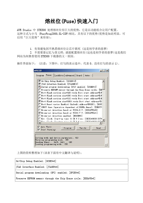
熔丝位(Fuse)快速入门AVR Studio 中 STK500 处理熔丝位有巨大的优势:它是以功能组合让用户配置。
这种方式与小马 (PnoyProg2000,SL-ISP)相比,具有以下的优势(优势是如此明显,可以用“巨大优势”来形容):1. 有效避免因不熟悉熔丝位让芯片锁死 (这是初学者的恶梦)2. 不需要靠记忆与查文档,就能配置熔丝位(这也是初学者的恶梦)这是我们网站为何推荐使用STK500下载器的又一原因。
操作界面如下: (注意:下图中,打勾的表示选中,代表0。
没有打勾的表示1)。
上图的资料整理如下(该表下面有中文翻译与说明):On-Chip Debug Enabled; [OCDEN=0]JTAG Interface Enabled; [JTAGEN=0]Serial program downloading (SPI) enabled; [SPIEN=0]Preserve EEPROM memory through the Chip Erase cycle; [EESAVE=0]Boot Flash section size=128 words Boot start address=$1F80; [BOOTSZ=11]Boot Flash section size=256 words Boot start address=$1F00; [BOOTSZ=10]Boot Flash section size=512 words Boot start address=$1E00; [BOOTSZ=01]Boot Flash section size=1024 words Boot start address=$1C00; [BOOTSZ=00] ; default value Boot Reset vector Enabled (default address=$0000); [BOOTRST=0]CKOPT fuse (operation dependent of CKSEL fuses); [CKOPT=0]Brown-out detection level at VCC=4.0 V; [BODLEVEL=0]Brown-out detection level at VCC=2.7 V; [BODLEVEL=1]Brown-out detection enabled; [BODEN=0]Ext. Clock; Start-up time: 6 CK + 0 ms; [CKSEL=0000 SUT=00]Ext. Clock; Start-up time: 6 CK + 4 ms; [CKSEL=0000 SUT=01]Ext. Clock; Start-up time: 6 CK + 64 ms; [CKSEL=0000 SUT=10]Int. RC Osc. 1 MHz; Start-up time: 6 CK + 0 ms; [CKSEL=0001 SUT=00]Int. RC Osc. 1 MHz; Start-up time: 6 CK + 4 ms; [CKSEL=0001 SUT=01]Int. RC Osc. 1 MHz; Start-up time: 6 CK + 64 ms; [CKSEL=0001 SUT=10]; default valueInt. RC Osc. 2 MHz; Start-up time: 6 CK + 0 ms; [CKSEL=0010 SUT=00]Int. RC Osc. 2 MHz; Start-up time: 6 CK + 4 ms; [CKSEL=0010 SUT=01]Int. RC Osc. 2 MHz; Start-up time: 6 CK + 64 ms; [CKSEL=0010 SUT=10]Int. RC Osc. 4 MHz; Start-up time: 6 CK + 0 ms; [CKSEL=0011 SUT=00]Int. RC Osc. 4 MHz; Start-up time: 6 CK + 4 ms; [CKSEL=0011 SUT=01]Int. RC Osc. 4 MHz; Start-up time: 6 CK + 64 ms; [CKSEL=0011 SUT=10]Int. RC Osc. 8 MHz; Start-up time: 6 CK + 0 ms; [CKSEL=0100 SUT=00]Int. RC Osc. 8 MHz; Start-up time: 6 CK + 4 ms; [CKSEL=0100 SUT=01]Int. RC Osc. 8 MHz; Start-up time: 6 CK + 64 ms; [CKSEL=0100 SUT=10]Ext. RC Osc. - 0.9 MHz; Start-up time: 18 CK + 0 ms; [CKSEL=0101 SUT=00]Ext. RC Osc. - 0.9 MHz; Start-up time: 18 CK + 4 ms; [CKSEL=0101 SUT=01]Ext. RC Osc. - 0.9 MHz; Start-up time: 18 CK + 64 ms; [CKSEL=0101 SUT=10]Ext. RC Osc. - 0.9 MHz; Start-up time: 6 CK + 4 ms; [CKSEL=0101 SUT=11]Ext. RC Osc. 0.9 MHz - 3.0 MHz; Start-up time: 18 CK + 0 ms; [CKSEL=0110 SUT=00]Ext. RC Osc. 0.9 MHz - 3.0 MHz; Start-up time: 18 CK + 4 ms; [CKSEL=0110 SUT=01]Ext. RC Osc. 0.9 MHz - 3.0 MHz; Start-up time: 18 CK + 64 ms; [CKSEL=0110 SUT=10]Ext. RC Osc. 0.9 MHz - 3.0 MHz; Start-up time: 6 CK + 4 ms; [CKSEL=0110 SUT=11]Ext. RC Osc. 3.0 MHz - 8.0 MHz; Start-up time: 18 CK + 0 ms; [CKSEL=0111 SUT=00]Ext. RC Osc. 3.0 MHz - 8.0 MHz; Start-up time: 18 CK + 4 ms; [CKSEL=0111 SUT=01]Ext. RC Osc. 3.0 MHz - 8.0 MHz; Start-up time: 18 CK + 64 ms; [CKSEL=0111 SUT=10]Ext. RC Osc. 3.0 MHz - 8.0 MHz; Start-up time: 6 CK + 4 ms; [CKSEL=0111 SUT=11]Ext. RC Osc. 8.0 MHz - 12.0 MHz; Start-up time: 18 CK + 0 ms; [CKSEL=1000 SUT=00]Ext. RC Osc. 8.0 MHz - 12.0 MHz; Start-up time: 18 CK + 4 ms; [CKSEL=1000 SUT=01]Ext. RC Osc. 8.0 MHz - 12.0 MHz; Start-up time: 18 CK + 64 ms; [CKSEL=1000 SUT=10] Ext. RC Osc. 8.0 MHz - 12.0 MHz; Start-up time: 6 CK + 4 ms; [CKSEL=1000 SUT=11]Ext. Low-Freq. Crystal; Start-up time: 1K CK + 4 ms; [CKSEL=1001 SUT=00]Ext. Low-Freq. Crystal; Start-up time: 1K CK + 64 ms; [CKSEL=1001 SUT=01]Ext. Low-Freq. Crystal; Start-up time: 32K CK + 64 ms; [CKSEL=1001 SUT=10]Ext. Crystal/Resonator Low Freq.; Start-up time: 258 CK + 4 ms; [CKSEL=1010 SUT=00] Ext. Crystal/Resonator Low Freq.; Start-up time: 258 CK + 64 ms; [CKSEL=1010 SUT=01] Ext. Crystal/Resonator Low Freq.; Start-up time: 1K CK + 0 ms; [CKSEL=1010 SUT=10] Ext. Crystal/Resonator Low Freq.; Start-up time: 1K CK + 4 ms; [CKSEL=1010 SUT=11] Ext. Crystal/Resonator Low Freq.; Start-up time: 1K CK + 64 ms; [CKSEL=1011 SUT=00] Ext. Crystal/Resonator Low Freq.; Start-up time: 16K CK + 0 ms; [CKSEL=1011 SUT=01] Ext. Crystal/Resonator Low Freq.; Start-up time: 16K CK + 4 ms; [CKSEL=1011 SUT=10] Ext. Crystal/Resonator Low Freq.; Start-up time: 16K CK + 64 ms; [CKSEL=1011 SUT=11] Ext. Crystal/Resonator Medium Freq.; Start-up time: 258 CK + 4 ms; [CKSEL=1100 SUT=00] Ext. Crystal/Resonator Medium Freq.; Start-up time: 258 CK + 64 ms; [CKSEL=1100 SUT=01] Ext. Crystal/Resonator Medium Freq.; Start-up time: 1K CK + 0 ms; [CKSEL=1100 SUT=10] Ext. Crystal/Resonator Medium Freq.; Start-up time: 1K CK + 4 ms; [CKSEL=1100 SUT=11] Ext. Crystal/Resonator Medium Freq.; Start-up time: 1K CK + 64 ms; [CKSEL=1101 SUT=00] Ext. Crystal/Resonator Medium Freq.; Start-up time: 16K CK + 0 ms; [CKSEL=1101 SUT=01]Ext. Crystal/Resonator Medium Freq.; Start-up time: 16K CK + 4 ms; [CKSEL=1101 SUT=10] Ext. Crystal/Resonator Medium Freq.; Start-up time: 16K CK + 64 ms; [CKSEL=1101 SUT=11] Ext. Crystal/Resonator High Freq.; Start-up time: 258 CK + 4 ms; [CKSEL=1110 SUT=00] Ext. Crystal/Resonator High Freq.; Start-up time: 258 CK + 64 ms; [CKSEL=1110 SUT=01] Ext. Crystal/Resonator High Freq.; Start-up time: 1K CK + 0 ms; [CKSEL=1110 SUT=10] Ext. Crystal/Resonator High Freq.; Start-up time: 1K CK + 4 ms; [CKSEL=1110 SUT=11] Ext. Crystal/Resonator High Freq.; Start-up time: 1K CK + 64 ms; [CKSEL=1111 SUT=00] Ext. Crystal/Resonator High Freq.; Start-up time: 16K CK + 0 ms; [CKSEL=1111 SUT=01] Ext. Crystal/Resonator High Freq.; Start-up time: 16K CK + 4 ms; [CKSEL=1111 SUT=10] Ext. Crystal/Resonator High Freq.; Start-up time: 16K CK + 64 ms; [CKSEL=1111 SUT=11] 上表的英文翻译说明如下:英文中文On-Chip Debug Enabled 片内调试使能JTAG Interface Enabled JTAG 接口使能Serial program downloading (SPI) enabled 串行编程下载(SPI) 使能 (ISP下载时该位不能修改)Preserve EEPROM memory through the ChipErase cycle;芯片擦除时EEPROM的内容保留Boot Flash section size=xxxx words 引导(Boot)区大小为xxx个词Boot start address=$yyyy; 引导(Boot)区开始地址为 $yyyy Boot Reset vector Enabled 引导(Boot)、复位向量使能Brown-out detection level at VCC=xxxx V; 掉电检测的电平为 VCC=xxxx 伏Brown-out detection enabled; 掉电检测使能Start-up time: xxx CK + yy ms 启动时间 xxx 个时钟周期 + yy 毫秒Ext. Clock; 外部时钟Int. RC Osc. 内部 RC(阻容) 振荡器Ext. RC Osc. 外部 RC(阻容) 振荡器Ext. Low-Freq. Crystal; 外部低频晶体Ext. Crystal/Resonator Low Freq 外部晶体/陶瓷振荡器低频Ext. Crystal/Resonator Medium Freq 外部晶体/陶瓷振荡器中频Ext. Crystal/Resonator High Freq 外部晶体/陶瓷振荡器高频注:以上中文是对照 ATmega16的中、英文版本数据手册而翻译。
Fuse知识详解
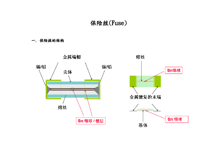
保险丝(Fuse)一.保险丝的结构
二.保险丝的工作原理
制作保险丝的材料及其形状确定了其电阻R.当电流流过时就会发热,随着时间的增加其发热量也增加.电流与电阻的大小确定了产生热量的速度,保险丝的构造与其安装的状况确定了热量耗散的速度.若产生热量的速度小于热量耗散的速度时,保险丝是不会熔断的;若产生热量的速度等于热量耗散的速度时,在相当长的时间内它也不会熔断;若产生热量的速度大于热量耗散的速度,那么产生的热量就会越来越多,又因有一定比热及质量,其热量的增加就表现为温度的上升,当温度升高到保险丝的熔点以上时保险丝就发生了熔断.以下为保险丝的发热量公式:
Q=0.24I2Rt
其中Q是发热量,0.24是一个常数,I是流过导体的电流,R是导体的电阻,t是电流流过导体的时间.
三. 保险丝的作用
保险丝又称为熔断器,IEC127标准将它定义为“熔断体(fuse-link)".它是一种安装在电路中,保证电路安全运行的电器元件.其作用是:当电路发生故障或异常时,随电流不断升高,并且升高的电流有可能损坏电路中的某些重要器件或贵重器件,也有可能烧毁电路甚至造成火灾.若电路中正确地安置了保险丝,则保险丝就会在电流异常升高到一定的高度和一定的时候,自身熔断切断电流,从而起到保护电路安全运行的作用.
六.保险丝的选择应用
a> 用于USB电源输入,根据USB规格限定电压为5V,最大电流为500mA,故若使用USB电源一般应加一小于500mA电流的保险丝加以保护.
b> 用于DSC整个系统,通过系统的组成按各元件功率的最大值,确定最低开机电压,然
后计算在最低电压时系统的电流,然后根据此电流选择合适的保险丝.保险丝的熔化热能值可依据
右表进行计算。
fuse 保险丝的工作原理

《fuse 保险丝的工作原理》
fuse 保险丝是一种常见的电路保护元件。
保险丝的工作原理是基于电流的热效应。
当电路中的电流超过保险丝的额定电流时,保险丝会发热。
如果电流持续增大,保险丝的温度会不断升高。
当温度达到保险丝的熔点时,保险丝会熔断,从而切断电路,保护电器设备和电路不受损坏。
例如,在一个家庭电路中,如果某个电器发生短路,电流会急剧增大。
如果没有保险丝的保护,过大的电流可能会导致电线过热起火,甚至引发火灾。
但是,由于安装了保险丝,当电流超过保险丝的额定电流时,保险丝会熔断,切断电路,从而避免了危险的发生。
保险丝的额定电流是根据电路的负载情况来选择的。
如果额定电流选择过大,当电路发生故障时,保险丝可能不会及时熔断,起不到保护作用;如果额定电流选择过小,保险丝可能会在正常工作时频繁熔断,影响电器设备的正常使用。
此外,保险丝还有不同的类型,如玻璃管保险丝、陶瓷保险丝、贴片保险丝等。
不同类型的保险丝适用于不同的场合,用户可以根据实际情况选择合适的保险丝。
FUSE基本知识及工作原理

HQ C #B#i
B、熔断特性表:由几个规定的具有代表性的负载电流值和对应的熔断时间范围所组成的表 格。各安全标准都已明确规定,这是验收保险丝的最主要依据。
EF _ /XKy$
fc%T\ _B J
例如 UL、CSA、MIT/KTLA 种规格快速熔断型,规定为: ur.cJ I4`
g < D Ol%
要求:试验前后电压降变化不应超过 10%,且标识仍清楚可辩,端帽焊点不出现任何劣变。
n aH[% k% X
qTTxs.M>)
七、保险丝适用的电路: C+vgZ PQE
pF]U xX!
1、特快速和快速熔断型保险丝管:适用于较恒定电流的电路,或浪涌电流较小的电路,且 电路中存在抗冲击脆弱元件或部件。
.F9 i* o,K
3、保险丝寿命的测试评估: P".| nFu&-
rRXd Q Ip
在 IEC 标准中规定有“耐久性试验法”,而 UL 标准中无类似的规定。 w> qTNk d
, $ lVN}&
IEC 标准中的耐久性试验即是寿命试验,其方法是,在正常温度下使用直流电源测试: Bc VG- ( ;
eGo0 ?u~
K\ H v '[
--- UL 测试通过、CSA 互认的列名/认可安全标志,等同于 q7PsY& c
+DDb#O
2、JIS 标准:日本电器安全标准。小型电流保险丝管标准为 JIS C6575。 _ X'#.V gT
j>p{u595~
安全标志: P[! Nfx' 4:
~ I9P<) v
1、被选用保险丝的额定电压,应大于被保护回路的输入电压。 m{8c F3) M
- 1、下载文档前请自行甄别文档内容的完整性,平台不提供额外的编辑、内容补充、找答案等附加服务。
- 2、"仅部分预览"的文档,不可在线预览部分如存在完整性等问题,可反馈申请退款(可完整预览的文档不适用该条件!)。
- 3、如文档侵犯您的权益,请联系客服反馈,我们会尽快为您处理(人工客服工作时间:9:00-18:30)。
额定电压
保险丝熔断与否取决于流过它的电流的大小,与电路 的工作电压无关。保险丝的额定电压是从安全使用保险丝 角度提出的,它是保险丝处于安全工作状态所安置的电路 的最高工作电压。这说明保险丝只能安置在工作电压小于 等于保险丝额定电压的电路中。只有这样保险丝才能安全 有效地工作,否则,在保险丝熔断时将会出现持续飞弧和 被电压击穿而危害电路的现象。
额定电流
保险丝的额定电流并非保险丝的熔断电流, 额定电流仅是一种规格的标称,而流过保险丝的 电流大到何种地步、何时熔断这在保险丝产品标 准中对它有详细的规定,又因标准的不同而规定 有所不同。
保险丝有一个"熔断系数"其值大于"1"(一般 在1.1至1.5之间),它是"常规不熔断电流"与"额 定电流"的比值。由此可以看出,即使流过保险丝 的电流大于它的额定电流而未超过常规不熔断电 流,保险丝也不应该发生熔断现象。
保险丝的作用是:当电路发生故障或异常时,伴随着 电流不断升高,并且升高的电流有可能损坏电路中的某些 重要器件或贵重器件,也有可能烧毁电路甚至造成火灾。 若电路中正确地安置了保险丝,那么,保险丝就会在电流 异常升高到一定的高度和一定的时候,自身熔断切断电流, 从而起到保护电路安全运行的作用。
二、工作原理
FUSE
APPLICATIONS
一、何谓保险丝
保险丝也被称为熔断器,IEC127标准将它定义为 “熔断体(fuse-link)”。它是一种安装在电路中,保证电
路安全运行的电器元件。
最早的保险丝于一百多年前由爱迪生发明,由于当 时的工业技术不发达白炽灯很贵重,所以,最初是将它用 来保护价格昂贵的白炽灯的。
通常有两个,它是熔体与电路联接的重要部件,它必须有良好的导电性,不应产生 明显的安装接触电阻 三、支架部分
保险丝的熔体一般都纤细柔软的,支架的作用就是将熔体固定并使三个部分成为 刚性的整体便于安装、使用,它必须有良好的机械强度、绝缘性、耐热性和阻燃性, 在使用中不应产生断裂、变形、燃烧及短路等现象;
保险丝的分断能力
当介于常规不熔断电流与相关标准规定的额 定分断能力(的电流)之间的电流作用于保险丝 时,保险丝应能满意地动作,而且不会危及周围 环境。保险丝被安置的电路的预期故障电流必须 小于标准规定的额定分断能力电流,否则,当故 障发生保险丝熔断时会出现持续飞弧、引燃、保 险丝烧毁、连同接触件一起熔融、保险丝标记无 法辨认等现象。当然,劣质保险丝的分断能力达 不到标准规定的要求,使用时同样会发生上述的 危害。
分
保护形式
过电流保护 过热保护 特慢速保险丝TT
熔断速度
慢速保险丝T 中速保险丝M
快速保险丝F
特快速保险丝FF
类
体积 额定电压
大型 中型 小型 微型 高压保险丝 低压保险丝 安全电压保险丝
慢速保险丝
慢速保险丝也叫延时保险丝,它的延时特性表现在电 路出现非故障脉冲电流时保持完好而能对长时间的过载提 供保护。
有些电路在开关瞬间的电流大于几倍正常工作电流, 尽管这种电流峰值很高,但是它出现的时间很短,我们称 它为脉冲电流也有称它为冲击电流或叫它为浪涌电流。普 通的保险丝是承受不了这种电流的,这样的电路中若使用 的是普通保险丝恐怕就无法正常开机了,若使用更大规格 的保险丝,那么当电路过载时又得不到保护。
延时保险丝的熔体经特殊加工而成,它具有吸收能量 的作用,调整能量吸收量就能使它即可以抗住冲击电流又 能对过载提供保护。
保险丝的电压降是保险丝在额定电流条件下,其两端 的电压降。它反映了保险丝的内阻,其值不应过大。若将 内阻(电压降)过大的保险丝安装在电路中,它将影响电 路的系统参数,使得电路不能正常工作。标准对电压降不 仅有其值的上限规定,而且对其一致性也作了规定。
保险丝的温升
保险丝的温升是指保险丝中流过1.1倍 (110%)额定电流时,保险丝的温度上升值,即 实测温度减去环境温度的值。UL标准将其上限规 定在75Co。因为保险丝的熔体对温度较为敏感, 在一定高的温度长时间的作用下,它的熔点及阻 抗将发生变化,这种变化会影响保险丝的准确性。 这就是通常说的保险丝老化。老化的保险丝使用 于电路中是非常危险的,所以,我们在制作和使 用保险丝时都应该注重保险丝的温升。同理,我 们也应该注意到,即使经过长时间使用的保险丝 未发生熔断,它也有可能已经老化了,此时最好 进行更换。
依下面的公式不难看出保险丝的简单的工作原理了:
Q=IRT
Q:发热量 0.24:是一个常数 I:流过导体的电流 R:导体的电阻 T:电流流过导体的时间
三、构造
保险丝由三个部分组成:
一、熔体部分 它是保险丝的核心,熔断时起到切断电流的作用,同一类、同一规格保险丝的熔体,
材质要相同、几何尺寸要相同、电阻值尽可能地小且要一致,最重要的是熔断特性要 一致; 二、电极部分
备注: 电力电路及大功率设备所使用的保险丝,除此三部分外,还有灭弧装置,因为这类 保险丝所保护的电路不仅工作电流较大,而且当熔体发生熔断时其两端的电压也很高, 往往会出现熔体已熔化(熔断)甚至已汽化,但是电流并没有切断,其原因就是在熔 断的一瞬间在电压及电流的作用下,保险丝的两电极之间发生拉弧现象。这个灭弧装 置必须有很强的绝缘性与很好的导热性,且呈负电性。石英砂就是常用的灭弧材料。 另外,还有一些保险丝有熔断指示装置,它的作用就是当保险丝动作(熔断)后其 本身发生一定的外观变化,易于被维修人员发现,例如:发光、变色、弹出固体指示 器等。