太阳能充电器使用说明书
新世代太阳能充电器说明书
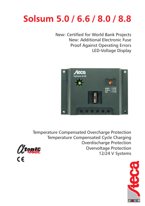
New:Certified for World Bank ProjectsNew:Additional Electronic Fuse Proof Against Operating ErrorsLED-Voltage DisplayTemperature Compensated Overcharge ProtectionTemperature Compensated Cycle ChargingOverdischarge Protection Overvoltage Protection12/24V SystemsSolsum 5.0/6.6/8.0/8.8T e c h n i c a l a l t e r a t i o n s c a n b e m a d e w i t h o u t p r i o r n o t i c e .I l l u s t r a t i o n s a n d d e s c r i b t i o n s d o n o t c l a i m t o b e c o m p l e t e .-S 03.674-01.02Our newest,and fourth,generation of solar charge controllers sets new standards in solar technology.For the first time a solar charge controller is offered in the market which is equipped with an integrated circuit (ASIC )specially designedfor solar charging.This integrated circuit,called Atonic ,provides a charge controller with new functions.Atonic is more than protective device for your battery,and contains the most recent and innovative technolgy.Overcharge protection is provided by a pulse-with-modulated shunt controller which guarantees quick and gentle charging of the battery (characteristic IV curve ).Wear-resistant MOSFET transistors are used for the overdischarge protection in this charge controllers,whereby a maintenance-free operation with an extremely long product life is ensured.Absolutely new in this price class is a cycle charging,boost charging and a temperature compensation which are regularly integrated in these charge controllers.An LED colour display gives information about voltage of the accumulator.Safety Features:Charging Functions:Overvoltage protection by integrated varistor Wrong polarity protection at Battery and ModuleProof against operation errors Built-in fuseElectronically short circuit protected Voltage-display by changing colour Low voltage disconnection LVD Shunt regulator -fast and gentle charging Time-delayed overdischarge protectionTemperature compensation by built-in sensor Automatic voltage adaption Cycle charging Boost charging Schottky diode MOSFET switchLED-display of charging functionred 11,8V yellow to red-yellow 12,3V green 12,8V Solsum Charge Controllers set new Standards in this Price and Power Class!T echnical Data:For a detailed description please see the AtonIC data sheet.AtonIC is a registered trademark of Steca GmbH.*1)Athon was an Egyptian god called:"Master of the Sun"®Solarix,AtonIC,the LED colour display and the hybrid control system,G9317097.1and G 9317338.5are both registered under German patent and Trade Name Office.。
太阳能充电控制器使用说明书

风光互补+LED 恒流一体机使用说明书■ 主要特点:1、本公司自主研发新型风光互补降压型MPPT + LED 升压型恒流一体机控制器;2、具有蓄电池浮充、涓充、过充、过放、反接保护;风机电子卸荷、转速检测、自动刹车、手动刹车保护;负载恒流输出、降功率调节、电子短路、过载保护;太阳能独特的防反接、防反充保护等全自动控制;以上保护均不损坏任何部件。
3、风力发电机采用独特的降压型MPPT 功能,具有转速检测、过速保护,风机过充自动卸荷、恒压、限流充电功能;风机转速和刹车恢复时间都可随意设定、修改;4、太阳能也采用了降压型MPPT 功能,串联式充电主回路,使充电回路的电压损失较使用二极管的充电电路降低近一半,充电效率较非PWM 高3%-6%,增加了用电时间;过放恢复的提升充电,正常的直充,浮充自动控制方式使系统有更长的使用寿命;同时具有高精度温度补偿。
5、负载使用升压型恒流方式,转换效率可达98%,可在线调整LED 输出电流,电流从30mA —3300mA 可调,并且可分四个时段,分别对亮灯时控、功率进行调节。
6、直观的LED 发光管指示当前系统运行状态,通过指示灯可以清楚的了解系统使用情况,以及故障报警状态。
7、所有控制全部采用工业级芯片,能在寒冷、高温、潮湿环境运行自如。
同时使用了晶振定时控制,定时控制精确。
8、使用了直观的LED 数码管显示设置,一键式操作即可完成所有设置,定时时间与数码管显示数字一一对应,显示更直观。
9、外壳防水采用独特的结构设计,使得外壳与散热片之间密封结合,只需将端子一面朝下安装,皆可起到安全的防水效果,顶端有安装挂件孔,即方便了安装,也起到了防水作用,同时大型散热片更加达到良好的散热效果,可有效延长控制器的使用寿命。
■ 控制器面板图:■ 系统说明:本控制器专为风力发电和太阳能发电直流供电系统、LED 照明设备设计专用,使用了专业电脑芯片的智能化控制。
采用一键式轻触开关,可完成所有操作及设置。
LandStar E EU系列产品说明书:太阳能充电器

1 2LandStar E/EU series——Solar Charge Controller1.Safety Information•Read all of the instructions in the manual before installation.•DO NOT disassemble or attempt to repair the controller.•Install external fuse or breaker as required.•Do disconnect the solar module and fuse/ breakers near to battery beforeinstalling or moving the controller.•Power connections must remain tight to avoid excessive heating from aloose connection.•Only charge batteries that comply with the parameters of controller.•Battery connection may be wired to one battery or a bank of batteries.•Risk of electric shock, the PV and load can produce high voltages when thecontroller is working.2. OverviewThe LandStar E series controller is a PWM charge controller that adopts themost advanced digital technique. It’s an easy operation and cost efficientcontroller featured as:•3-Stage intelligent PWM charging:Bulk, Boost/Equalize, Float•Support 3 charging options: Sealed, Gel, and Flooded•Battery status LED indicator can indicates battery situation•Battery temperature compensation function•With humanized settings, operation will be more comfortable and convenient•The USB will provide power supply that can charge for electronicequipment(LS EU series only)•Battery type and load output can be set via button•Extensive Electronic protection3. Product Features4. WiringStep 2:Connect the system in the order of ❶battery →❷ load→❸PV arrayin accordance with Figure 2-2,”Schematic Wiring Diagram” and disconnect thesystem in the reverse order❸❷❶.NOTE: While wiring the controller do not close the circuit breaker orfuse and make sure that the leads of "+" and "-" poles are connectedcorrectly.NOTE: A fuse which current is 1.25 to 2 times the rated current ofthe controller must be installed on the battery side with a distancefrom the battery not greater than 150 mm.NOTE: If an inverter is to be connected to the system, connect theinverter directly to the battery, not to the load side of the controller.5. LED Indicators1) Charging and load status indicator2) Battery status indicator①Voltage value for 12V system at 25℃, please use 2× in 24V system ;②"○"LED indicator on; "×"LED indicator off.6. Setting Operation1)Load ON/OFF SettingWhen the controller is powered on, press the button to control the load output.2)Battery Type SettingOperation:Step 1: Enter setting mode by pressing button for 5s until the battery statusLEDs are flashing.Step 2: Select the desired mode by pressing button.Step 3: The mode will be saved automatically without any operation for 5S andLED will stop flashing.Figure 1 Product FeatureFigure 2 Connection diagram3 4Below parameters are in 12V system at 25 ºC, please double the values in7. Protection • Battery Over Voltage ProtectionWhen the battery voltage reaches to the set point of Over Voltage Disconnect Voltage(OVD), the controller will stop charging the battery to protect the battery from being over charged to break down. • Battery Over Discharge ProtectionWhen the battery voltage reaches to the set point of Low Voltage Disconnect Voltage(LVD), the controller will stop discharging the battery to protect the battery from being over discharged. • Load Overload ProtectionLoad will be switched off when 1.25 times rated current overload happens. User has to reduce load appliance, then press the button or repower the controller.• Load Short Circuit ProtectionLoad will be switched off when load short circuit (≥3 times rated current) happens. User has to clear short circuit, then press the button or repower the controller.• High Voltage Transients ProtectionThe controller is protected against small high voltage transients. In lightning prone areas, additional external suppression is recommended.nominal value, the controller will automatically turn off loads in 60s, 5s and 1s respectively.10. Disclaimer This warranty does not apply under the following conditions: • Damage from improper use or use in an unsuitable environment.• PV or load current, voltage or power exceeding the rated value of controller. • User disassembly or attempted repair the controller without permission. • The controller is damaged due to natural elements such as lighting. • The controller is damaged during transportation and shipment.Any changes without prior notice! Version number :V2.09. Technical Specifications。
MPPT太阳能充电控制器使用操说明书 2
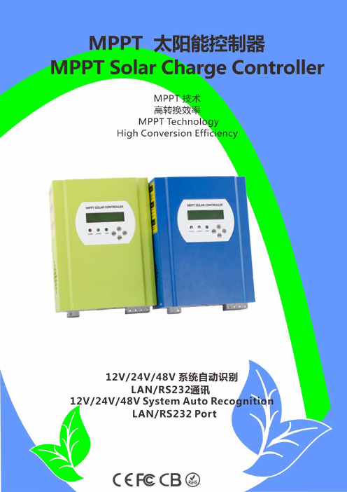
-一、产品介绍这是一款最大功率点智能跟踪(MPPT)太阳能充放电控制器,比传统的控制器充电效率提高了30%~60%,其具有系统自动识别、PV宽电压范围输入、可为多种蓄电池充电、智能控制放电模式,RS232或LAN通讯等优点,是目前最高端的MPPT太阳能充放点控制器。
二、产品特点1、充电模式MPPT;转换效率高达99%,可比传统的控制器节约30%~60%太阳能电池板;2、12V/24V/48V系统自动识别,方便客户使用;3、PV宽电压范围输入,最大为DC150V;4、记忆功能,保存设置功能;如日期,时间,发电量等;5、充电方式:三阶充(恒流、恒压、浮充),有效了延长了蓄电池的寿命;6、放电模式有常开模式,常关模式,双时段控制开关模式,PV电压控制开关模式,PV控制开+延时关模式等;7、客户可自行选择为4类常用电池(密封铅酸电瓶,排放式电瓶,胶体电瓶,镍镉电瓶)充电,并且可自定义为其它种类的电池充电;8、LCD和LED显示各种参数,如型号,PV输入电压,电池类型,充电电压,充电电流,充电功率,工作状态等;还可为客户加公司名称、网址、LOGO等;9、RS232和LAN通讯,IP和网关地址可自行设置满足全球区域使用,并可提供通讯协议,方便客户统一集成管理;10、提供专业的11国语言上位机软件,可显示和设置充放电系统的整个工作状况和工作参数;11、智能设计,可在线升级,客户享受终生升级服务;12、采用的元器件均为品牌,耐高温不低于105℃,理论设计寿命10年;13、产品符合满足2002/95/EC环保要求,没有镉、氢化物和氟化物等;14、整机配套:整机+光盘(上位机软件)+RS232通讯线+温度传感线+说明书;15、产品通过CE,ROHS,FCC,PSE认证;可配合客户通过各项认证;16、正常保修期二年,并且可提供3~10年延长保修服务;三、产品参数备注:1、我司可为客户定制36V/72V/96V等非常规MPPT控制器,提供OEM和ODM服务;四、产品配套序号数量配件名称11PC控制器整机(蓝色或绿色可选,或OEM)22pc挂耳(用于控制器固定在墙壁)34set螺丝(用于挂耳锁在控制器)41pc RJ45转RS232连接线51pc电池温度传感线62pc保险丝(DC输出)71pc说明书(用户手册)附:五、上位机软件和测试软件如图所示备注:1)产品配套上位机软件,适合于各个PC系统;图示:上位机设置参数界面图示:上位机工作状态界面图示:上位机开关机,发电量清零界面图示:测试软件工作状态界面蓝色外观绿色外观包装配件配套上位机软2)贸易商提供中性的上位机软件和中性光盘,或者带客户LOGO的软件;2)WIN7,WIN8打开软件时,请用管理员身份登入;详见说明书;五、控制器显示和设置信息备注:1)以上显示的信息为我司SMART2在某个时刻工作的举例;不同阶段显示的参数都会变化,如工作模式,充电电流,充电模式,充电功率等;在故障模式下显示故障信息;2)以上有数据显示表示可以更改;有关显示或设置的步骤,请查看说明书;XX六、控制器连接图图-Array备注:1)以上为离网型系统连接图;2)通讯连接方式有多种,详见说明书;七、其他参数请参见设计大纲、技术文件、产品说明书等;八、联系方式深圳市爱庞德新能源科技有限公司。
太阳能充电器操作指南说明书

Installation andoperating instructionsSolar charge controller 10 A / 15 A / 20 A / 30 A1. About this manualThese operating instructions are part of the product.X Read these operating instructions carefully before use,X keep them over the entire lifetime of the product,X and pass them on to any future owner or user of this product.1.1 ApplicabilityThis manual describes the installation, function, operation and maintenance of the solar charge controller.Further technical information is provided in a separate technical manual.1.2 UsersThese operating instructions are intended for end customers. A technical expert must be consulted in cases of uncertainty.1.3. Description of symbolsSafety instructions are identified as follows:Type, source and consequences of the danger!X Measures for avoiding dangerInstructions relating to the functional safety of the system are in bold type.2. Safety2.1 Proper usageThe solar charge controller may only be used in PV systems for charging and controlling lead-acid batteries in accordance with this operating manual and the charging specifi-cations of the battery manufacturer.2.2 Improper usageNo energy source other than a solar generator may be connected to the solar charge controller. No mains devices, diesel generators or wind generators may be connected. Do not connect any defective or damaged measuring equipment.2.3 General safety instructionsX Follow the general and national safety and accident prevention regulations.X Never alter or remove the factory plates and identification labels.X Keep children away from PV systems.X Never open the device.2.4 Other risksDanger of fire and explosionX Do not use the solar charge controller in dusty environments, in the vicinity of solvents or where inflammable gases and vapours can occur.X No open fires, flames or sparks in the vicinity of the batteries.X Ensure that the room is adequately ventilated.X Check the charging process regularly.X Follow the charging instructions of the battery manufacturer.Battery acidX Acid splashes on skin or clothing should be immediately treated with soap suds and rinsed with plenty of water.X If acid splashes into the eyes, immediately rinse with plenty of water. Seek medical advice.2.5 Fault behaviourOperating the solar charge controller is dangerous in the following situations:• The solar charge controller does not appear to function at all.• The solar charge controller or connected cables are visibly damaged.• Emission of smoke or fluid penetration.• When parts are loose.X In these cases immediately remove the solar charge controller from the solarmodules and battery.3. Description3.1 FunctionsThe solar charge controller• monitors the state of charge of the battery bank, • controls the charging process,• controls the connection/disconnection of loads.This optimises battery use and significantly extends its service life.A battery charging algorithm protects the battery from harmful states. Activation of the three deep discharge functions (LVW, LVD and LVR) is dependent upon the state of charge (SOC). The switching thresholds lie within the corresponding voltage window in accordance with the discharge or charging current.3.2 Construction3.3LED displaysThe solar charge controller consists of the following components:1. info LED2. 4 LEDs for displaying the state of charge (red, yellow, green 1 and green 2)3. terminal block for connecting the solar module4. terminal block for connecting the battery5. terminal block for connecting the loads loads4. InstallationDanger of explosion from sparking! Danger of electric shock!X The solar charge controller may only be connected to the local loads and the bat-tery by trained personnel and in accordance with the applicable regulations.X Follow the installation and operating instructions for all components of the PV sys-tem.X Ensure that no cables are damaged.4.1 Mounting the solar charge controller4.1.1 Mounting location requirements• Do not mount the solar charge controller outdoors or in wet rooms.• Do not subject the solar charge controller to direct sunshine or other sources of heat.• Protect the solar charge controller from dirt and moisture.• Mount upright on the wall (concrete) on a non-flammable substrate.• Maintain a minimum clearance of 10 cm below and around the device to ensure unhindered air circulation.• Mount the solar charge controller as close as possible to the batteries (with a safety clearance of at least 30 cm).4.1.2 Fastening the solar charge controllerX Mark the position of the solar charge controller fastening holes on the wall.X Drill 4 Ø 6 mm holes and insert dowels.X Fasten the solar charge controller to the wall with the cable openings facing down-wards, using 4 oval head screws M4x40 (DIN 7996).4.2 Connection4.2.1 Preparing the wiringThe cross section of the connection cable depends on the power output of the solar charge controller.The table above applies to the following cable lengths:• 10 m solar module connection cable• 2 m battery connection cable• 5 m load connection cableConsult a dealer if the specified cable lengths are inadequate.An additional external fuse (not provided) must be connected to the battery con-nection cable, close to the battery pole.The external fuse prevents cable short circuits. A 40 A fuse can be used for all controller types.4.2.2 ConnectionDanger of explosion from sparking! Danger of electric shock!Solar modules generate electricity under incident light. The full voltage is present, even when the incident light levels are low.X Protect the solar modules from incident light during installation, e.g. cover them. X Never touch uninsulated cable ends. X Use only insulated tools.X Ensure that all loads to be connected are switched off. If necessary, remove thefuse. X Connections must always be made in the sequence described below.1st step: Connect the batteryX Label the battery connection cables as a plus cable (A+) and aminus cable (A–).X Lay the battery cables in parallel between the solar charge control-ler and the battery.Xterminals on the solar charge controller (with the battery symbol). X If necessary, remove any external fuse.X Connect battery connection cable A+ to the positive pole of the battery. X Connect battery connection cable A– to the negative pole of the battery. X Replace the external fuse in the battery connection cable.X If the connection polarity is correct, the info LED illuminates green.2nd step: Connect the solar moduleX Ensure that the solar module is protected from incident light. X Ensure that the solar module does not exceed the maximum per-missible input current.X Label the solar module connection cables as a plus cable (M+) anda minus cable (M–).X Lay both solar module connection cables in parallel between the solar module andthe solar charge controller.X First connect the M+ solar module connection cable to the correct pole of the leftpair of terminals on the solar charge controller (with the solar module symbol), then connect the M– cable.X Remove the covering from the solar module.Connection sequence1. battery2. solar module3. loads3rd step: Connect loadsNotes• Connect loads that must not be deactivated by the solar chargecontroller deep discharge protection, e.g. emergency lights or radioconnection, directly to the battery.• Loads with a higher current consumption than the device outputcan be directly connected to the battery. However, the solar chargecontroller deep discharge protection will no longer intervene. Loadsconnected in this manner must also be separately fused.X Label the load connection cables as a plus cable (L+) and a minus cable (L–).X Lay the load connection cables in parallel between the solar charge controller and the loadX First connect the L+ load cable to the correct pole of the right pair of terminals on the solar charge controller (with the lamp symbol), then connect the L– cable.X Replace the load fuse or switch on the load.4th step: Final workX Fasten all cables with strain relief in the direct vicinity of the solar charge controller (clearance of approx. 10 cm).4.2.3 GroundingThe components in stand-alone systems do not have to be grounded – this is not stand-ard practice or may be prohibited by national regulations (e.g.: DIN 57100 Part 410: Prohibition of grounding protective low voltage circuits). Consult the technical manual for more information.4.2.4 Lightning protectionIn systems subjected to an increased risk of overvoltage damage, we recommend installing additional lightning protection / overvoltage protection to reduce dropouts. Consult the technical manual for more detailed information.5. OperationThe solar charge controller immediately begins operation once the battery is connected or the external fuse is inserted.The displays of the solar charge controller show the current operating mode. User intervention or user settings are not required.Protection functionsThe following integrated protection functions of the solar charge controller ensure that the battery is handled as gently as possible.The following protection functions are part of the basic function of the controller:• Overcharge protection• Deep discharge protection• Battery undervoltage protection• Solar module reverse current protectionThe following installation faults do not destroy the controller. After correcting the fault, the device will continue to operate correctly:• Protection from solar module short circuits / incorrect solar module polarity1)• Protection from short circuits at the load output or excessive load current• Protection from battery connection with incorrect polarity• Protection from solar module overcurrent• Protection from device overtemperature• Protection from overvoltage at the load output• Protection from the wrong connection sequence1) The reverse-polarity protection of the solar module in a 24 V system is only provided up to an open-circuit module voltage of 36 V.6. MaintenanceThe solar charge controller is maintenance-free.All components of the PV system must be checked at least annually, according to the specifications of the respective manufacturers.X Ensure adequate ventilation of the cooling element.X Check the cable strain relief.X Check that all cable connections are secure.X Tighten screws if necessary.X Terminal corrosion7.Faults and remediesLoad cannot be operated+info LED flashes red+2. green LED flashes • load output is switched offdue to excessive batteryvoltagethe load output automaticallyswitched on again as soon asthe battery voltage lies withinthe permissible range• incorrect grounding X check the grounding• external charging source isnot voltage-limitedX check the external chargingsourceX if necessary, switch off exter-nal charging sourcesLoad cannot be operated+info LED illumi-nates green • defective load or installationerrorX connect load correctlyX replace loadBattery is not charged • solar module not connected X connect the solar module • solar module connected withincorrect polarityX connect the solar modulewith the correct polarity• short circuit at solar moduleinputX correct the cause of the shortcircuit• incorrect solar modulevoltageX use a solar module of thespecified voltage• solar module defective X replace the solar moduleBattery display jumps quickly • large pulse current X tune the current consump-tion to match the batterycapacity• battery is defective X replace the battery8. T echnical dataNOTE:Technical data that varies from the above is given on a device label. Subject to change without notice.*If the battery voltage is less than 9 V, the controller switches off and cannot recharge the battery itself, even if sufficient power is available from the module.9. Legal guaranteeAccording to the German legal requirements, for this product the customer has a2 year legal guarantee.The seller will remove all manufacturing and material faults that occur in the product during the legal guarantee period and affect the correct functioning of the product. Natural wear and tear does not constitute a malfunction. Legal guarantee does not apply if the fault can be attributed to third parties, unprofessional installation or com-missioning, incorrect or negligent handling, improper transport, excessive loading, use of improper equipment, faulty construction work, unsuitable construction location or improper operation or use. Legal guarantee claims shall only be accepted if notification of the fault is provided immediately after it is discovered Legal guarantee claims are to be directed to the seller.The seller must be informed before legal guarantee claims are processed. For processing a legal guarantee claim an exact fault description and the invoice / delivery note must be provided.The seller can choose to fulfil the legal guarantee either by repair or replacement. If the product can neither be repaired nor replaced, or if this does not occur within a suitable period in spite of the specification of an extension period in writing by the customer, the reduction in value caused by the fault shall be replaced, or, if this is not sufficient taking the interests of the end customer into consideration, the contract is cancelled. Any further claims against the seller based on this legal guarantee obligation, in particular claims for damages due to lost profit, loss-of-use or indirect damages are excluded, unless liability is obligatory by German law.。
太阳能充电器的使用方法与效率提升技巧

太阳能充电器的使用方法与效率提升技巧太阳能充电器作为一种环保、便携的充电设备,越来越受到人们的关注和喜爱。
它利用太阳能转化为电能,为我们的手机、平板电脑等电子设备提供便捷的充电方式。
然而,很多人在使用太阳能充电器时遇到了一些问题,比如充电速度慢、充电效率低等。
本文将介绍太阳能充电器的使用方法,并提供一些提升充电效率的技巧。
首先,正确选择太阳能充电器非常重要。
市场上有各种各样的太阳能充电器,功率、电池容量、充电接口等都有所不同。
在购买时,我们应该根据自己的需求选择合适的充电器。
例如,如果你需要给手机充电,选择一个功率适中、带有USB接口的充电器就足够了;如果你需要给平板电脑充电,那么选择一个功率较大、带有多个充电接口的充电器会更加方便。
其次,正确使用太阳能充电器也能提高充电效率。
太阳能充电器最好在阳光充足的地方使用,如户外阳台、露天露台等。
将充电板朝向阳光,确保太阳能充分照射到充电板上,这样能够最大限度地提高充电效率。
另外,避免遮挡物的存在也是提高充电效率的关键。
在使用充电器时,要确保充电板的周围没有遮挡物,如树叶、建筑物等,这样可以避免阻碍太阳能的照射,提高充电效果。
此外,合理安排充电时间也是提高充电效率的重要因素。
太阳能充电器的充电效率受到光照强度的影响,因此在阳光充足的时候使用充电器效果会更好。
比如,在晴天或阳光明媚的日子里使用充电器,充电速度会明显快于阴天或多云的日子。
因此,我们可以合理安排充电时间,选择在天气晴好的时候使用太阳能充电器,这样可以提高充电效率,节省充电时间。
另外,对于长时间不使用的太阳能充电器,我们应该注意保养和存储。
首先,要保持充电板的清洁,避免灰尘、油渍等物质的附着。
这些污垢会影响充电板的光吸收能力,从而降低充电效果。
其次,我们应该妥善存放充电器,避免长时间暴露在阳光下或潮湿的环境中。
长时间的阳光暴晒会损坏充电器的电池和电路,影响使用寿命。
因此,我们可以将充电器存放在干燥、通风的地方,以延长其使用寿命。
太阳能智能移动电源使用说明书2010

太阳能智能充电器/移动电源一、产品介绍:本产品是一款多用途的太阳能智能充电器/移动电源,内置高容量可充电聚合物锂电池,太阳能电池板功率最高可达1.6w。
通过智能MCU输出多组电压,可随时随地对你的手机、数码相机、PDA、PSP、GPS、DV、MP3、MP4家庭节能设备等进行充电或供电。
本产品具有安全可靠,容量大,寿命长,功能多等优点。
金属外壳设计、时尚高雅、携带方便。
二、使用方法:注:本产品在初次使用时,请在使用前对本产品进行两次以上完全充、放电,以提高内置电池的使用效率。
请按下面步骤使用:1、使用之前请给本产品充电。
有三种方法可选择:A、太阳能充电:打开产品,放置于太阳直射处或强光上,太阳光将自动转化为电能自动为内置的锂电池进行充电。
此时产品的LED指示灯为红色,表示正在充电,当电池充满后,LED指示灯将变为绿色。
(内部设计电路有自动断电保护功能)B、电脑USB对产品充电:将产品用USB线连接到电脑USB端口,此时产品的LED指示灯为红色,表示正在充电,当电池充满后,LED指示灯将变为绿色。
(内置先进的电源管理芯片不会对你的PC产生任何的危害)C、用交流适配器充电:充电时USB指示灯会亮起,产品的LED指示灯为红色,表示正在充电,当电池充满后,LED指示灯将变为绿色,并关闭所有的输出。
另外,还可使用车载充电器对本产品充电。
2、当给您的手机或数码产品充电前,请仔细查看您的产品说明书或电源适配器,了解您产品的充电电压,然后按ON/OFF按钮(3秒一5秒)即可开机,开机时,红色LED电压指示灯亮,开机后产品默认输出4.8V,长按调节按钮(3秒一5秒)即可以调节输出4.8、5.8V、8.4V、9.0V。
每长按一次,可调整一次电压输出,调节好电压后,将充电转换线的USB 5P插头连接到本产品,再将另一头与相应的转接头连接,然后再连接到您的产品上,即可进行充电。
充电时,在您的手机和数码产品上将显示正在充电的提示,您可以在进行充电的同时使用手机进行通话。
KZ1-A 型太阳能智能充电控制器 使用说明书
KZ1-A 型太阳能智能充电控制器使用说明书12V5A■ 主要特点:1、 使用了高性能单周期单片机、内部看门狗保护、软件复位功能。
2、 使用控制器内部设置专用软件,用户可设置不同使用环境、不同功能的控制功能。
3、 采用无触点开关技术、具有多种工作模式、输出模式选择,以满足用户各种需要。
4、 采用了高效PWM 蓄电池的充电模式,保证蓄电池工作在最佳的状态,大大延长蓄电池的使用寿命 5、 智能PWM 功率输出控制,路灯模式具备渐亮渐暗软启动 和强光 弱光模式(可调),并可根据蓄电池的容量自动调整输出功率,提高太阳能电池的转换效率和蓄电池的使用寿命。
6、 采用了直观的数字LED 显示及设置,能实时显示蓄电池充、放电状态、容量及参数设置、控制等信息。
7、 具有TVS 防雷、过压、欠压、负载短路、防接反等全自动保护控制,以上保护均不损坏任何部件。
8、 所有控制芯片全部采用工业级,控制器能在寒冷、高温、潮湿环境运行自如。
9、 采用小体积、全密封防水机壳,使安装更加便捷。
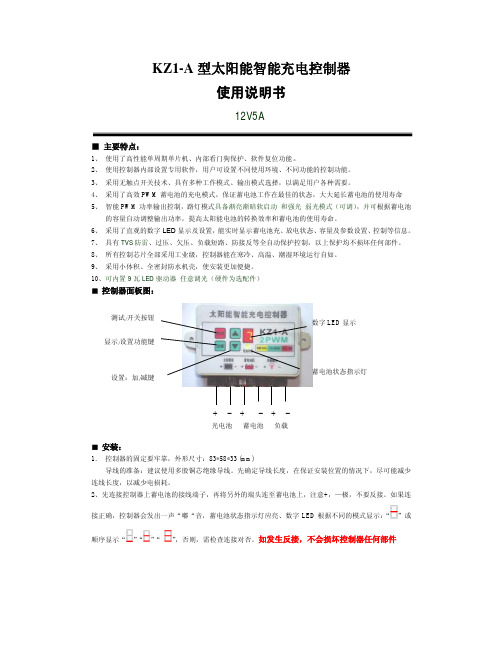
10、可内置9瓦LED 驱动器 任意调光(硬件为选配件) ■ 控制器面板图:■ 安装:1. 控制器的固定要牢靠,外形尺寸:83*58*33 (mm)导线的准备:建议使用多股铜芯绝缘导线。
先确定导线长度,在保证安装位置的情况下,尽可能减少连线长度,以减少电损耗。
2、先连接控制器上蓄电池的接线端子,再将另外的端头连至蓄电池上,注意+,—极,不要反接。
如果连接正确,控制器会发出一声“嘟“音,蓄电池状态指示灯应亮、数字LED 根据不同的模式显示:“”或顺序显示“”“”“”,否则,需检查连接对否。
如发生反接,不会损坏控制器任何部件蓄电池状态指示灯设置:加/减键数字LED 显示3、连接光电池导线,先连接控制器上光电池的接线端子,再将另外的端头连至光电池上,,注意+,—极,不要反接,如果有阳光,数字LED根据不同的模式顺序显示:“”“”“”或顺序显示“”“”“”。
- 1、下载文档前请自行甄别文档内容的完整性,平台不提供额外的编辑、内容补充、找答案等附加服务。
- 2、"仅部分预览"的文档,不可在线预览部分如存在完整性等问题,可反馈申请退款(可完整预览的文档不适用该条件!)。
- 3、如文档侵犯您的权益,请联系客服反馈,我们会尽快为您处理(人工客服工作时间:9:00-18:30)。
太阳能充电器使用说明书
1、
2、
3、
4、
5、
6、
7、
8、
9、
10
11
12
13
1.1 利用太阳能或交流电源可直接给外接电器使用及充电,或对本产品内的畜电池充电。
1.2 配有高亮照明,标准的USB端口输出,可供MP3、MP4、手机、PDA、数码相机等USB产品直接使用或充电。
1.3 本充电器的蓄电池充电时,具备稳压、恒流、过充电和过放电的保护功能。
1.4 配置充电状态指示及蓄电池电量检测功能。
二、特点:
2.1 轻便、环保,实用性强,尤其便于户外或野外应急供电与充电。
2.2 当手机没有电量的情况时,放在阳光的照射下,太阳能充电器所发出的电量可直接供手机通话使用。
2.3 3-5小时即可对市面上的手机充满电。
2.4 配有液晶显示屏,用电量检测按钮可查看充电状态和蓄电池电量。
三、技术规格:
3.1整机:
①产品尺寸:113X55X26.5mm。
②重量:约165g。
③输出功率:5W。
④工作参数:
A. 用太阳能对蓄电池充电,7-9小时可充满。
B. 用交流电源适配器对本机蓄电池充电,3小时可充满。
C. 蓄电池充满电量后可连续照明工作48小时。
D. 用太阳能直接对手机进行充电,3-5小时可充满。
E. 蓄电池满电时, 3-5小时可对手机充满电。
F. 交流电源适配器参数:AC100-240V,50-60Hz。
DC输出5.3V,500mA。
G. 内用蓄电池参数:3.7V,1200mAh安全环保锂离子蓄电池。
H. 太阳能光伏电池参数:DC6V,160mA。
四、使用说明:
4.1 蓄电池电量检测:按电量检测键,如图(1)所示,液晶显示屏会显示蓄电池电量。
4.2 照明功能:如图(2)所示,再将转换开关置于()。
4.3 用本充电器的蓄电池给外接电器供电使用或充电时:将适配头插入手机或其他电器接口,另一端插入本充电器USB插孔(如图5所示),再将转换开关置于()此图标。
4.4 用交流电源给蓄电池充电时:应先将交流电源插头插入(本说明书所设定),其电压允许范围内的交流电插座,另一端插入本充电器输入插孔,再将转换开关置,于()位置,如图(6)所示。
4.5 用太阳光给蓄电池充电时:把每片太阳能电池板拉开,放在阳光下直射,再将转换开关置于()
或()位置即可,如图(3)所示。
4.6 用太阳能直接给手机等外接电器供电使用或充电时:应先将适配头插入手机等电器插孔,另一端连接插入本充电器USB插口,再将转换开关置于(),如图(4)所示。
4.7 适配功能:如果选用的适配头无法适配连接您使用的电器时,请不要强行插入,而应选用合适的适配头。
4.8 本充电器内置自动保护系统:当外部电路短路时,本充电器会停止工作,此时可以用太阳光或交流电源适配器对其充电激活,即可继续工作。
五、注意事项
5.1 初次使用本充电器时,请在阳光直射下充电7-9小时,或用交流电源充电3小时。
5.2 请勿使用有腐蚀性溶液擦拭本充电器。
5.3 请勿重摔、重压,以免造成损坏。
5.4 请勿将本产品长期置于潮湿环境下,以免影响其寿命。
5.5 吸收阳光充电时,应适当调整其位置与角度,让光线全面照射太阳能电池板,便于快速充电。
5.6 使用本充电器对您的电器充电时,最好将您的电器置于关机或待机状态。
六、附件
各种电器适配头(选配)。
七、包装
7.1 包装:每套产品一个包装,外形尺寸118X60X44 mm
7.2 外箱尺寸: 每箱装20盒。
外形尺寸310X185X122 mm
八、本产品申请专利号:200720179160.2
本说明书如有任何变动恕不另行通知。
本厂对此说明书享有最终解释权。