艾默生无线仪表的介绍
艾默生智能无线技术

自组织网络
– 精确时间同步全网格架构 (TSMP) – IEEE 802.15.4 和扩频技术 (DSSS) – 全面的安全措施 – 通讯可靠,几乎适应所有的干扰环境,同其 它无线网络友好共存 – 自动重新组态,无需人工介入
Mesh网络
– 无线网格网络
– 动态不断扩展的网络架构 – 任意的两个设备均可以保持无线互联
控制室 工作
I/O
集线
工作 机柜设计 跳线和终端 接线图 电缆布置
接线盒
工作 JB 设计 跳线和终端 接线图 电缆布置
I/O列表和控制器 选型 电源、接地、保险 丝设计 I/O 设计 备件选型 机柜设计
穿线管和布 电缆 P&IDs 工艺描述 分包安装
WirelessHART HCF, FF 和 PNO IEC正式标准 宣布成立WCT WirelessHART IEC62591 wireless cooperation 开始销售 team WirelessHART 用户现场互操作性 第一版WirelessHART 测试成功(Siemens, 标准被批准 ABB, EMR, E&H, P&F, etc)
内容提要
艾默生无线产品的引入
– 用户面临的问题和困难 – WFN自组织无线网络
用户关心无线技术的问题
– – – – 无线技术标准 安全措施 电能 系统集成方案
无线产品简介
– 无线设备介绍 – HART无线适配器 – 无线控制
12
Emerson Confidential 27-Jun-01, Slide 12
WirelessHART - 与 HART相同的 “应用层"
艾默生无线现场链路快速入门指南说明书
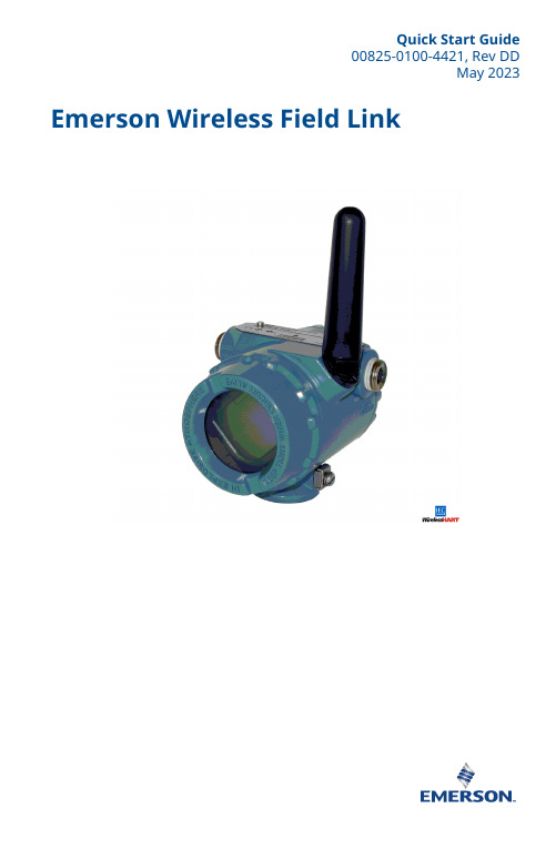
Quick Start Guide00825-0100-4421, Rev DDMay 2023 Emerson Wireless Field LinkQuick Start Guide May 2023This guide provides basic guidelines for the Emerson Wireless Field Link. It does not provide instructions for diagnostics, maintenance, service, or troubleshooting. This guide is alsoavailable electronically on .WARNINGFailure to follow these installation guidelines could result in death or serious injury.Ensure only qualified personnel perform the installation.Explosions could result in death or serious injury.Installation of the transmitters in a hazardous environment must be in accordance with the appropriate local, national, and international standards, codes, and practices. Kindly review the Product Certifications section for any restrictions associated with a safe installation.Electrical shock could cause death or serious injury.Avoid contact with the leads and terminals. High voltage that may be present on leads cancause electrical shock.This device complies with Part 15 of the FCC Rules. Operation is subject to the following conditions:This device may not cause harmful interference.This device must accept any interference received, including interference that may causeundesired operation.This device must be installed to ensure a minimum antenna separation distance of 8-in. (20 cm) from all persons.ContentsWireless considerations (3)Physical installation (6)Verify operation (8)Reference information (9)Declaration of Conformity (11)Product certifications (14)/Rosemount1 Wireless considerations1.1 Power up sequenceTo achieve a simpler and faster network installation, verify thefollowing before the power modules are installed in any wireless fielddevices:•Emerson Wireless Field Link is installed and functioning properly•Wireless I/O is installed and functioning properly•Beginning with the closest, wireless field devices are powered upin order of proximity to the Wireless Field Link1.2 Mounting locationMount the Wireless Field Link in a location that allows convenientaccess to the host system network (wireless I/O) as well as thewireless field device network.Find a location where the Wireless Field Link has optimal wirelessperformance. Ideally this will be 15 to 25 ft. (4,6 to 7,6 m) above theground or 6 ft. (2 m) above obstructions or major infrastructure.A Control roomB GroundC Field linkD Mast or pipeE InfrastructureMay 2023Quick Start Guide Quick Start Guide3Quick Start Guide May 2023 1.3 Antenna positionPosition the antenna vertically, either straight up or straight down.Verify a distance of at least 3 ft. (1 m) is maintained from anylarge structure, building, or conductive surface to allow for clearcommunication to other devices.Figure 1-2: Antenna Position1.4 Conduit plugReplace the temporary orange plugs with the included conduit plugsusing approved thread sealant.Figure 1-3: Conduit PlugsAAA Conduit plug/Rosemount1.5 Intended useThe Wireless Field Link must be used in conjunction with a networkmanager or network Gateway. The Wireless Field Link then functionsas a translator between the wired network and a wireless fieldnetwork.Figure 1-4: Example System ArchitectureABC DEFA Host systemB Control networkC Network managerD Field linkE Wireless field networkF Wireless field devicesMay 2023Quick Start Guide Quick Start Guide5Quick Start Guide May 2023 2 Physical installation2.1 Pipe mountingProcedure1.Insert larger U-bolt around 2-in. pipe/mast, through thesaddle, through the L-shaped bracket, and through the washerplate.e a 1/2-in. socket-head wrench to fasten the nuts to theU-bolt.3.Insert smaller U-bolt around base the Wireless Field Link andthrough the L-shaped bracket.e a 1/2-in. socket-head wrench to fasten the nuts to theU-bolt.Figure 2-1: Mounting2.2 Power and data wiringWARNINGThe 781 Wireless Field Link data communication terminals A (+) and B(-) must never be connected directly to a power supply. Doing so maydamage the device.After removing the terminal block cover, the communicationterminals (Data A and Data B) are on the left side of the terminalblock. Connecting these terminals to anything other than thecorresponding data terminals of the 1410S or 1410D Gateway maydamage the 781 Wireless Field Link.Procedure1.Remove housing cover labeled “Field Terminals.”/Rosemount2.Connect the positive power lead to the “+” power terminal and the negative power lead to the “–” terminal.3.Connect the Data + lead to the “A (+)” terminal and the Data –lead to the “B (–)” terminal.4.Plug and seal any unused conduit connections.5.Replace the housing cover.Figure 2-2: Emerson Wireless Field Link Terminal DiagramABCD2.3 GroundingGround the Wireless Field Link enclosure in accordance with national and local electrical codes. The most effective grounding method is a direct connection to earth ground with minimal impedance. Ground the Wireless Field Link by connecting the external ground lug to earth ground. The connection should be 1 Ω or less.May 2023Quick Start GuideQuick Start Guide 7Quick Start Guide May 2023 3 Verify operation3.1 Power-up sequenceUpon applying power to the Wireless Field link the LCD display meterwill activate and display a series of startup screen. The followingscreens are displayed during startup:1.Startup Screen 1 – All segments on2.Startup Screen 2 – Device identification3.Startup Screen 3 – Tag4.Startup Screen 4 – Status3.2 Normal operationAfter the initial startup screens are displayed, the Wireless Field Linkwill cycle through the following periodic screens:1.Electronics Temperature Screen2.Percent Range Screen3.Wired Interface Usage4.Radio Interface UsageThe Wireless Field Link continues to rotate through each periodicscreen through the course of normal operation. If any diagnosticor fault condition occurs, a corresponding diagnostics screen willappear./Rosemount4 Reference informationFigure 4-1: Emerson Wireless Field Link Terminal DiagramABCDNoteThe Emerson Wireless Field Link requires separate twisted shield pairs (four wires) for power and data.May 2023Quick Start GuideQuick Start Guide 9Quick Start Guide May 2023 Figure 4-2: Emerson Wireless Field Link Dimensional DrawingTable 4-1: Emerson Wireless Field Link Specificationsabove maximum ambient temperature./Rosemount5 Declaration of ConformityMay 2023Quick Start GuideQuick Start Guide 11Quick Start Guide May 2023/RosemountMay 2023Quick Start GuideQuick Start Guide13Quick Start Guide May 2023 6 Product certificationsRev 2.36.1 European Directive InformationA copy of the EU Declaration of Conformity can be found at theend of the Quick Start Guide. The most recent revision of the EUDeclaration of Conformity can be found at .6.2 Ordinary Location CertificationAs standard, the transmitter has been examined and tested todetermine that the design meets the basic electrical, mechanical,and fire protection requirements by a nationally recognized testlaboratory (NRTL) as accredited by the Federal Occupational Safetyand Health Administration (OSHA).6.3 Installing in North AmericaThe US National Electrical Code® (NEC) and the Canadian ElectricalCode (CEC) permit the use of Division marked equipment in Zonesand Zone marked equipment in Divisions. The markings must besuitable for the area classification, gas, and temperature class. Thisinformation is clearly defined in the respective codes.6.4 USAI5 USA Intrinsic SafetyCertificate80011697Markings Class I, II, III Division 1 Groups A, B, C, D, E, F, G T4; ClassI, II, III Division 2, Groups A, B, C, D, F, G T4 T4(-40 °C ≤ T a≤ +70 °C); Class I Zone 0, AEx ia IIC T4 Ga; Class I Zone 2,AEx ic IIC T4 Gc; Zone 21 AEx ia IIIC T90 °C Db; Zone 22AEx ic IIIC T90 °C DcStandards FM 3600:2011, FM 3610:2018, FM 3611:2018, ANSI/UL60079-0:2019, ANSI/UL 60079-11:2014Warnings/Conditions of Acceptability1.Installed as per. Control drawing 01410-1300 for Hazardousand Non-Hazardous areas.2.Must be installed with a Resistive Barrier./RosemountMay 2023Quick Start Guide3.The plastic enclosure may constitute a potential electrostaticignition risk and must not be rubbed or cleaned with a drycloth.4.The measured capacitance between the equipment enclosureand metallic conduit adapter is 21pF. This must be consideredonly when the Model 781S is integrated into a system wherethe process connection is not grounded.6.5 CanadaI1 Canada Intrinsic SafetyCertificate80011697Markings Class I, II, III Division 1 Groups A, B, C, D, E, F, G T4; ClassI, II, III Division 2, Groups A, B, C, D, F, G T4 T4(-40 °C ≤ T a≤ +70 °C); Ex ia IIC T4 Ga; Ex ic IIC T4 Gc; Ex ia IIIC T90 °CDb; Ex ic IIIC T90 °C DcStandards CAN/CSA C22.2 No 60079-0:2019, CAN/CSA C22.2 No.60079-11:2014, CSA C22.2 No.213 – 2017Warnings1.Installed as per. Control drawing 01410-1300 for Hazardousand Non-Hazardous areas.2.Must be installed with a Resistive Barrier.3.The plastic enclosure may constitute a potential electrostaticignition risk and must not be rubbed or cleaned with a drycloth.4.The measured capacitance between the equipment enclosureand metallic conduit adapter is 21pF. This must be consideredonly when the Model 781S is integrated into a system wherethe process connection is not grounded.6.6 EuropeI1 ATEX Intrinsic SafetyCertificate Baseefa11ATEX0059XStandards EN IEC 60079-0:2018, EN 60079-11: 2012Markings II 1 G Ex ia IIC T4 Ga, T4(–40 °C ≤ T a≤ +70 °C)Quick Start Guide May 2023Special Conditions for Safe Use (X)1.The plastic antenna may present a potential electrostaticignition hazard and must not be rubbed or cleaned with a drycloth.2.The Rosemount 781 enclosure is made of aluminum alloy andgiven a protective paint finish; however, care should be takento protect it from impact or abrasion if located in a zone 0environment.3.The apparatus is not capable of withstanding the 500 Visolation test required by EN 60079-11. This must be taken intoaccount when installing the apparatus.6.7 InternationalI7 IECEx Intrinsic SafetyCertificate IECEx BAS 11.0028XStandards IEC 60079-0: 2011, IEC 60079-11: 2011Markings Ex ia IIC T4 Ga, T4(–40 °C ≤ T a≤ +70 °C)Special Conditions for Safe Use (X)1.The plastic antenna may present a potential electrostaticignition hazard and must not be rubbed or cleaned with a drycloth./RosemountMay 2023Quick Start Guide2.The Rosemount 781 enclosure is made of aluminum alloy andgiven a protective paint finish; however, care should be takento protect it from impact or abrasion if located in a zone 0environment3.The apparatus is not capable of withstanding the 500 Visolation test required by EN 60079-11. This must be taken intoaccount when installing the apparatus.6.8 EAC – Belarus, Kazakhstan, RussiaIM (EAC) Intrinsic SafetyCertificate RU C-US.Gb05.B.00643Markings0Ex ia IIC T4 Ga XSpecial Conditions for Safe Use (X)1.See certificate for special conditions.6.9 JapanI4 CML Intrinsic SafetyCertificate CML20JPN2401XMarkings Ex ia IIC T4 Ga (-40 °C ≤ T a≤ +70 °C), Ex ic IIC T4 Gc (-40°C ≤ T a≤ +70 °C)Special Conditions for Safe Use (X)See certificate.6.10 BrazilI2 INMETRO Intrinsic Safety (Rev 1 Only)Certificate UL-BR 20.1568XQuick Start Guide17Quick Start Guide May 2023 Markings Ex ia IIC T4 Ga (-40 °C ≤ T a≤ +70 °C), Ex ic IIC T4 Gc (-40°C ≤ T a≤ +70 °C)Standards ABNT NBR IEC 60079-0:2013, ABNT NBR IEC60079-11:2013Special Conditions for Safe Use (X)See certificate.6.11 ChinaI3 NEPSI本质安全证书GYJ20.1394X(CCC 认证)所用标准GB3836.1 – 2010, GB3836.4 – 2010, GB3836.20-2010标志Ex ia IIC T4 Ga特殊使用条件(X)1.产品外壳含有轻金属,用于0区时需注意防止由于冲击或摩擦产生的点燃危险。
艾默生简介

艾默生过程控制有限公司(费希尔-罗斯蒙特)一. 简介:罗斯蒙特公司是世界上最大的自动化仪器仪表公司,以生产优质压力、温度、流量、液位测量仪表及其他各种自动化仪表而闻名于世, 连续数年在美国《CONTROL》杂志组织的年度评比和客户调查中以显著的优势位居第一。
1.压力变送器罗斯蒙特公司始终如一的承诺就是:连续改进,产品具有向前、向后的兼容性,这使罗斯蒙特1151型和3051型压力变送器一直处于世界领先的地位。
变送器的市场不断变化。
过去,技术进步常常需要几十年的时间,而现在只需几年-甚至更短时间就可以完成了。
在这种情况下,今天安装的变送器是否能支持明天仪表能力新的进步,则成为至关重要的问题。
罗斯蒙特的变送器完全兼容新技术,是工厂跨入下个世纪的最佳途径。
仅仅在近四年中,1151的性能指标即提高了250%,例如,量程比已由15:1提高为40:1。
迄今为止,1151型压力变送器的安装量已超过600万台,以其优异的性能、可靠性和稳定性赢得了用户的一致称赞。
3051系列压力变送器,树立了变送器性能的新标准。
优异的总体性能-综合了参考精度、温度影响和静压影响,而不仅仅以参考精度作为变送器性能的指标;优异的长期性能-五年稳定性,而不是6个月,12个月或24个月;优异的动态性能-比典型变送器响应快5-10倍,可更有效地跟踪和控制过程变化。
3051C型Coplanar共面平台设计,为过程连接提供了最大的灵活性。
3051现场总线压力变送器已成功地投入工业运行。
最新推出的3051S可变规模变送器,不仅是性能极其优异的超级压力、差压变送器,而且是流量计、液位计。
总体技术性能和可靠性是现在世界上最好的3051C系列变送器的2倍。
3051S为现场自动化行业提供了新的价值平台!精度0.065%经典型,0.04%超级型,量程比200:1;10年稳定性和12年的寿命保证期.2. 温度变送器、温度传感器:罗斯蒙特公司是以温度产品起家的,第一个产品的航空用的高精度温度传感器,迄今已有38年温度产品制造经验。
艾默生 Rosemount 848T 高密度温度变送器 说明书

产品说明书00813-0106-4697, Rev SC2024 年 01 月Rosemount™ 848T 高密度温度测量系列产品■适合高密度应用的创新温度测量技术,可节省安装和操作成本。
■支持 RTD、热电偶、欧姆、毫伏、0–10 V 和 4–20 mA 信号的独立可组态输入。
■外壳选项和本安设计允许其安装在任何工艺区域附近,包括危险区域。
■Wireless HART®功能把 Plantweb™的全部优点延伸到以前难以到达的地点。
■行业领先的测量验证诊断,可识别各种过程问题,包括传感器性能衰减、传感器接线、高振动(影响测量)和异常过程变化。
Rosemount 848T2024 年 01 月高密度温度测量通过无线实现创新无线温度测量解决方案内容高密度温度测量 (2)Rosemount 848T F OUNDATION™现场总线温度变送器 (6)Rosemount 848T F OUNDATION™现场总线规格 (11)产品认证 (17)Rosemount 848T F OUNDATION现场总线尺寸图 (18)Rosemount 848T 无线温度变送器 (26)Rosemount 848T Wireless 规格 (30)产品认证 (35)Rosemount 848T Wireless 尺寸图 (36)F OUNDATION™现场总线能够实现高效测量,同时降低接线成本■国际公认的数字网络 (IEC 61158) 支持在单条双绞线上连接最多16 台设备。
■通过使用功能块实现高级计算。
■提供每个测量点的连续测量状态。
■通过减少接线、端接和本安安全栅的所需数量降低成本。
了解罗斯蒙特温度测量 Complete Point Solutions™的优点■艾默生提供一系列 RTD 和热电偶,为温度检测领域带来了优异的耐用性和罗斯蒙特可靠性。
■范围广泛的热电偶套管产品满足各种过程应用的苛刻要求。
体验全球一致性以及由全球罗斯蒙特温度测量产品生产基地提供的本地支持■世界一流的制造水平确保世界各地每家工厂的产品一致性以及满足任何工程需求的能力。
艾默生智能无线现场链接00825-0106-4421 DC版2020年9月快速安装指南说明书

快速安装指南00825-0106-4421, D C版2020年9月艾默生™智能无线现场链接2020 年 9 月2快速安装指南本指南提供智能无线现场连接的基本安装说明,不提供诊断、维护、检修或故障排查的说明。
本指南的电子版本也可从 获得。
警告不遵守这些安装准则可能会导致严重的人身伤害甚至死亡。
⏹确保仅由取得相关资质的人员进行安装。
爆炸可能会导致死亡或严重伤害。
⏹在易爆环境中安装本变送器时,请务必遵守适用的当地、国家和国际标准、规范及规程。
请核对产品证书一节中是否有与安全安装相关的任何限制。
触电可能会导致死亡或严重伤害。
⏹应避免接触引线或接线端子。
导线上可能存在的高电压会造成电击。
本设备符合 FCC 规范的第 15 部分的规定。
设备操作应符合下列条件:⏹本设备不会导致有害干扰。
⏹本设备必须接受任何接收到的干扰,包括可能会导致非预定操作的干扰。
⏹安装本设备时,必须确保天线与所有人员间的最小间隔距离为 20 厘米 (8 英寸)。
目录无线设备安装注意事项 . . . . . . . . . . . . . . . . . . . . . . . . . . . . . . . . . . . . . . . . . . . . . . . . . . . . . . 3物理安装 . . . . . . . . . . . . . . . . . . . . . . . . . . . . . . . . . . . . . . . . . . . . . . . . . . . . . . . . . . . . . . . . . . . 5验证操作 . . . . . . . . . . . . . . . . . . . . . . . . . . . . . . . . . . . . . . . . . . . . . . . . . . . . . . . . . . . . . . . . . . . 7参考信息 . . . . . . . . . . . . . . . . . . . . . . . . . . . . . . . . . . . . . . . . . . . . . . . . . . . . . . . . . . . . . . . . . . . 8订购信息 . . . . . . . . . . . . . . . . . . . . . . . . . . . . . . . . . . . . . . . . . . . . . . . . . . . . . . . . . . . . . . . . . . 10产品认证 . . . . . . . . . . . . . . . . . . . . . . . . . . . . . . . . . . . . . . . . . . . . . . . . . . . . . . . . . . . . . . . . . . 11快速安装指南32020 年 9 月无线设备安装注意事项上电次序在任何无线现场设备中安装电源模块之前,应安装好智能无线现场链接和无线 I/O ,并确保它们能正常工作。
艾默生 Micro Motion G系列流量和密度仪表 说明书

产品样本00813-0106-4630, Rev AA2023 年 10 月Micro Motion(高准)G 系列流量和密度仪表™出色的可靠性和安全性■无磨损或需要更换的移动部件,将维护工作降到最少,保证了长期的可靠性■激光蚀刻标签,即使在具有挑战性的环境中也非常耐用■可清洁、自排空设计连接■全系列的高准变送器选项和通信协议■通过创新的 Wi-Fi、Bluetooth®、2 线环路供电和以太网供电解决方案降低布线的复杂性■包括 Smart Meter Verification 在内的高级诊断易于使用■超紧凑式轻质传感器设计确保安装灵活性■具有值得信赖的高准电子元件,易于安装、集成和远程监测■简化的传感器选项和预选解决方案,便于订购G 系列科里奥利质量流量计和密度仪表2023 年 10 月测量原理作为科里奥利效应的实际应用,科里奥利质量流量计的工作原理是使得有介质流经的流量管发生振动。
尽管振动并非完整的圆形,仍形成了旋转坐标系统,从而引发科里奥利效应。
传感器将检测并分析流量管频率,相位差和振幅的变化。
具体的检测方法会因流量计设计不同而不同,这些被观测到的变化代表了流体的质量流量和密度。
密度测量测量管以其固有频率振动。
管道内流体质量的变化将导致管道固有频率发生相应的变化。
通过管道的频率变化来计算密度。
温度测量温度作为测量变量,可用作输出量。
此外,温度还可在传感器内部使用,以补偿温度变化对杨氏弹性模量的影响。
质量和体积流量测量测量管在力的作用下发生摆动,从而产生正弦波。
流量为零时,两根管道同相地发生振动。
有流量时,科里奥利力促使管道发生扭曲,从而引发相偏移。
测量正弦波之间的时差,此时差与质量流量成正比。
体积流量通过质量流量和密度测量结果来计算得到。
请观看此视频,详细了解科里奥利流量计如何测量质量流量和密度(单击链接,选择View Videos(查看视频)):https:// /en-us/automation/measurement-instrumentation/flow-measurement/coriolis-flow-meters。
艾默生 Plantweb Insight 无线压力表应用程序产品说明书
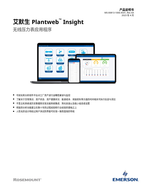
产品说明书MS-00813-1006-4541, Rev AA2023 年 4 月艾默生 Plantweb™ Insight无线压力表应用程序■可视化和分析软件平台对工厂资产进行战略性解读与监控■了解关于异常情况、资产状态、资产健康状况、能源成本、排放损失等方面的时间相关可执行信息与洞见■不靠主机系统或历史数据库实现无缝系统集成、简化安装以及极少组态或设置■预装的分析功能建立在数十年的过程经验和行业经验的基础之上■人性化的设计和经过用户测试的界面可实现一致而直观的导航功能和优点实时了解异常情况■资产监测应用程序套装,可利用数据分析和模型识别异常情况和故障。
■通过提醒和故障识别功能,在影响经济收益之前了解问题。
■直观且易于读取的视图突出显示高优先级的可执行信息。
安全可靠的轻量级软件包便于无缝集成到当前的基础架构■通过虚拟机轻松部署。
■随时从多种 Web 浏览器访问界面。
■人性化的设计便于快速、直观地启动和组态。
■与现有无线生态系统集成,以扩展功能并利用现有资产。
■不依靠 DCS、主机系统或历史数据库。
内容功能和优点 (2)用户界面 (4)无线压力表应用程序 (5)通讯规格 (6)订购信息 (7)技术规格 (9)艾默生 Plantweb Insight 2023 年 4 月/Rosemount2023 年 4 月艾默生 Plantweb Insight 通过完全可扩展的软件包和众多应用程序监测一种或数千种资产■应用程序基于关键资产,例如疏水器、泵、热交换器、泄压阀以及其他资产。
■从小处着手,或从单点监测所有资产。
■与其他商业系统(例如数据历史数据库)集成。
■可以部署在小型、大型或企业级运营中。
艾默生 Plantweb Insight 3用户界面PlantwebInsight 套件中的所有应用程序都采用相似的外观和风格,使用户获得一致的体验。
主要视图可分成三层。
仪表板仪表板页面是所监测资产类别的整体概览。
艾默生 采用 WirelessHART 协议的 Rosemount无线压力表 数据表

产品说明书00813-0106-4045, Rev EE2022 年 十一月采用Wireless HART®协议的 Rosemount™无线压力表艾默生提供的 Rosemount Wireless 压力表采用成熟的压力传感器技术,可提供准确、可靠的压力信息。
它具有高达 150 倍的过压保护和双层过程隔离特性,可以为用户提供更加安全的现场环境。
罗斯蒙特传感器技术通过更换传统压力表中阻碍报告或显示正确压力信息的机械部件,消除了许多仪表问题。
这款仪表采用 4.5 in. (114 mm) 大端面,便于观察现场。
它的安装后寿命最长可达 10 年,降低了维护成本,缩短了维护时间。
罗斯蒙特无线压力表2022 年 十一月产品优点符合传统仪表要求■量程 ±0.5% 的标称精度(符合 ASME B40.1 2A 级标准)■NPT、DIN、阀组、液位法兰和分体式密封件过程连接■表压、绝压、真空压、复合压和镜像测量类型■刻度范围为 15 inH2O (37.3 mbar) 至 10000 psi (689.5 bar)减少维护工作■成熟的罗斯蒙特压力传感器技术能够为您提供可靠读数,使用寿命长达 10 年。
■可以减少由振动、过压及其他环境因素引起的常见机械压力表故障。
■通过本地指示灯,您可以了解压力表是否正常运行。
提高人员安全■通过最大限度地减少操作员巡检,让人员远离危险区域。
■过压额定值范围为满量程的 1.5 倍至 150 倍,2 层过程隔离,让用户高枕无忧。
内容产品优点 (2)订购信息 (4)技术规格 (14)产品认证 (18)尺寸图 (22)2022 年 十一月罗斯蒙特无线压力表可以持续查看压力数据■凭借Wireless HART®技术获得更新速率为每分钟一次的精确读数。
■通过 4.5-in. (114 mm) 表盘,您可在本地查看压力读数。
使用资产位号随时获取信息新发运设备包含一个唯一的二维码资产位号,您可以通过它直接从设备访问序列化信息。
- 1、下载文档前请自行甄别文档内容的完整性,平台不提供额外的编辑、内容补充、找答案等附加服务。
- 2、"仅部分预览"的文档,不可在线预览部分如存在完整性等问题,可反馈申请退款(可完整预览的文档不适用该条件!)。
- 3、如文档侵犯您的权益,请联系客服反馈,我们会尽快为您处理(人工客服工作时间:9:00-18:30)。
无线仪表操作说明
LOGO
路径System settings→Protocols→Modbus下设置Baud Rat为9600,Unmapped Register Read Response?选择Zero Fill,Unmapped Register write Response?选 择IIIegal Data Address(其它参数均不做修改)
电池模块
LOGO
1.绿色电源模块,型号 701PGNKF:
绿色电源模块及无线装置包含一块 “D” 号基本锂 - 亚硫酰氯电池 (型号 701PGNKF )。每块电池含有大约 5.0 克锂。电压为3.9V。在正常条件下,只要电池和电池组保持 完整,电池材料就是自我包藏的,并且不会发生反应。应防止热损害、电气损害或机械损 害。应保护触点,防止过早放电。电池单元放电后,电池仍有危险。电源模块应存放在洁 净干燥的区域。为了使电源模块使用寿命达到最长,存放温度不应超过30 °C。
无线仪表操作说明
LOGO
在路径System settings→Protocols→Protocols And Ports中可选择、 设置通讯协议,选择会使用的通讯协议。点击Save Changes即可。
无线仪表操作说明
LOGO
在路径System settings→Protocols→Modbus下可设置选择设备寄存位置和设备 PV、QV、TV、SV、电池电压等。
I.S. Class 1 Div 2 Approvals
LOGO
罗斯蒙特 3051S无线压力变送器
建立在性能优良的3051S平台基础上
– 包括压力、差压液位、差压流量
大量丰富的 HART 数据和诊断信息
Smart Power™ 电池
– 5 年寿命
– 本质安全
CPS 供货
本地大液晶Leabharlann 示罗斯蒙特848T多点温度变送器
LOGO
罗斯蒙特248单点温度变送器
LOGO
248 无线温度变送器采用标准设计,拥有成熟的功能和规格,有助降低工厂成本, 提升测量可靠性。
经 IEC 认证的全兼容的248 无线方案无线无线248是通过HART提供丰富诊断数据 和可靠性能的智能无线温度解决方案。
1.接受各种传感器输入,此输入的灵活性可满足各种应用需求。 2.双室外壳高可靠性,可用于潮湿、腐蚀和 EMI/RFI 环境中。 3.环境温度补偿增强变送器性能。 4.无线输出的数据可靠性超过了 99%,可在需要时提供丰富的数据。
打开AMS Wireless Configurator选择Network Configuration,点击Add创 建一个新的网络
AMS Wireless Configurator组态软件的设置
LOGO
Select Network Component Type内有两种模式HART Modem是同过 第三方HART调制解调器对无线仪表进行组态,Wireless Network 是通 过读取网关数据对无线仪表进行组态,选择好组态方式点击Install进行 添加。
无线仪表操作说明
LOGO
在路径System settings→Gateway→Ethernet Communication下可更改 网关名称、IP地址、子网掩码,网关更改过网关名称、IP地址、子网掩码必须重 启才能生效。
无线仪表操作说明
LOGO
在路径System settings→Network→Network settings下可设置网关的 Network ID、Join KEY,需点击show join key才能显示Join KEY所设置的密 码。
无线仪表操作说明
LOGO
在路径System settings→Protocols→Modbus→Format Settings下的Value reported for error(floating pooint )可选择设备在故障情况下显示的值。
LOGO
AMS Wireless Configurator组态软件的设置
在可预测的安装条件下,规定电源模块使用寿命长达 10 年。 低电位警报 使维护工作安排更简便。 坚固的设计 允许在恶劣环境中使用。 锁扣式连 接方式便于进行更换,并可防止故障。
智能无线 THUM™ 适配器
LOGO
一、智能无线 THUM 适配器: 1.一种可在任何现有两线制或四线制设备上进行改装的设备 2.由无线电变送器、接收器、微处理器和天线组成 3.使您能够无线传输先前无法获取的 HART 测量和诊断信息
艾默生无线仪表
LOGO
智能 控制系统
智能 分析
智能 中断控制
智能 设备优化
智能无线
智能机器 健康状态
智能 测量 智能安全
1
艾默生WirelessHART系统构成示意图
LOGO
以上为现阶段艾默生WirelessHART系统构成示意图,无线现 场设备、带WirelessHART适配器的普通HART设备由智能无 线网关通过用户选用的通讯协议(Modbus、TCP/IP、OPC、 以太网等)将现场设备的信息传送到数据采集系统或控制系统。 部分HART设备在增加WirelessHART适配器后,一方面通过 智能无线网关以无线方式传送数据,另一方面又可保留原有的 HART总线方式传送数据。
AMS Wireless Configurator组态软件的设置
双击点击想要组态的仪表位号,进行组态(以无线压力变送器为例)
本(TCP/IPV4)属性。更改IP地址(I)为192.168.1.20(不能与网关的IP地址相 同),子网掩码(U)为255.255.255.0。如下图所示:
无线仪表操作说明
LOGO
1.2在IE浏览器输入192.168.1.10,进入网关,网关的账号为:admin,密码 为password(初始默认密码:default)。网关HOME为网关主界,界面中 ALL Devices为曾经连接过的设备数量,Live为当前连接的设备数量, Unreachable为当前未连接设备数量,Power module low为电池电量低的 设备数量,New栏内会显示最新连上设备,Changes栏内会显示更改过 数据的设备的位号、内容及修改时间。
AMS Wireless Configurator组态软件的设置
LOGO
通过Wireless Network 组态
点击下一步,在Smart wireless Gateway mane or IP Address中输入网关IP: 192.168.1.10点击Add添加,点击完成,网络组态完成。点击Close即可
4 级用户报警(HH、H、L 和 LL)
Alert “OFF”
Alert “ON”
Alert “OFF”
Units of measurement
Deadband Time
Alert Set Point
Assigned Variable
I.S. Class 1 Div 1 Approvals
LOGO
Intro Today!
罗斯蒙特1420无线网关
• 网络管理
– 简单强大安全网络 – 密钥轮换管理 – VPN
– 网络非常容易扩展
• 数据管理
– 大于99%的可靠性 – 趋势 – 与DCS通讯
– Modbus(TCP 和 RTU) – OPC – HTTP – 用户报警
• 设备管理
– 组态简单 – 设备诊断
缺点: 1.艾默生的无线仪表只能用他的软件。 2.采集数据的灵敏度不够高不能用在控制、联锁的仪表上。 3.抗干扰性差,受现场条件影响,通讯不稳定等。
现有的无线产品
LOGO
Collect
Route
Integrate & Validate
Measurement
In Plant
Pressure Flow +Discrete Level +Vibratio Temp. n
+Corrosio
1420 Wireless
Gateway
Remote
ROC Wireless
3051S n
Gateway for
Oil
648
&Gas
Control System, Historian
Seamless integration via
OPC, Ethernet, Modbus
无线仪表应用的场合
1.灌区 2.那种偏远的火炬点 3.旋转设备上 4.长输管线上
LOGO
无线仪表的优缺点
LOGO
优点: 1.能节省安装成本。 2.具有可靠性高, 自我管理,自我适应,安装简单,扩展灵活的特 点。 3.无需专业工具,同有线设备安装几乎一样,增加测点非常容易,移 动现有测点也非常容易。
无线仪表操作说明
LOGO
1.3 Devices为设备显示界面,可显示设备的Name 、Pv、Sv、Tv、Qv、 Last Update(最后一次更新时间),其中在Devices中可以选择设备显示个数。
无线仪表操作说明
LOGO
在Detailed Device Information中可以更改Tag Name、PV Units、Burst Rate(设备扫 描周期),点击 Edit HART Details,然后再Tag Name、PV Units、Burst Rate(设备扫描 周期)对应下方更改数据,最后在按Save HART Details完成数据更改(在此过程中可能 会有一段时间丢失数据),此外在View Additional status中还可以查看设备Neighboring Devices(连接到的其他设备)、Neighboring Devices Reliability(连接到的其他设备 的稳定性)、Path Stability(最优设备稳定性)、RSSI(最优设备信号强度),以此判断 设备的稳定性。(当RSSI小于-80设备有可能会掉线)