艾默生无线网关中文说明书(Gateway_CA)
艾默生无线现场链路快速入门指南说明书
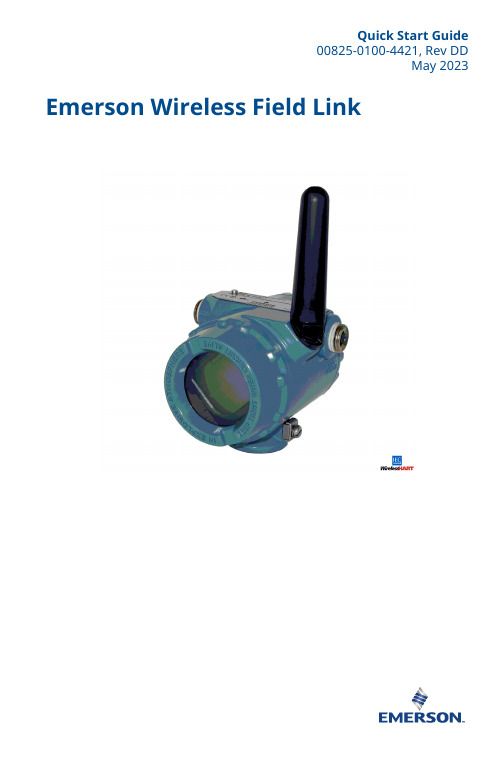
Quick Start Guide00825-0100-4421, Rev DDMay 2023 Emerson Wireless Field LinkQuick Start Guide May 2023This guide provides basic guidelines for the Emerson Wireless Field Link. It does not provide instructions for diagnostics, maintenance, service, or troubleshooting. This guide is alsoavailable electronically on .WARNINGFailure to follow these installation guidelines could result in death or serious injury.Ensure only qualified personnel perform the installation.Explosions could result in death or serious injury.Installation of the transmitters in a hazardous environment must be in accordance with the appropriate local, national, and international standards, codes, and practices. Kindly review the Product Certifications section for any restrictions associated with a safe installation.Electrical shock could cause death or serious injury.Avoid contact with the leads and terminals. High voltage that may be present on leads cancause electrical shock.This device complies with Part 15 of the FCC Rules. Operation is subject to the following conditions:This device may not cause harmful interference.This device must accept any interference received, including interference that may causeundesired operation.This device must be installed to ensure a minimum antenna separation distance of 8-in. (20 cm) from all persons.ContentsWireless considerations (3)Physical installation (6)Verify operation (8)Reference information (9)Declaration of Conformity (11)Product certifications (14)/Rosemount1 Wireless considerations1.1 Power up sequenceTo achieve a simpler and faster network installation, verify thefollowing before the power modules are installed in any wireless fielddevices:•Emerson Wireless Field Link is installed and functioning properly•Wireless I/O is installed and functioning properly•Beginning with the closest, wireless field devices are powered upin order of proximity to the Wireless Field Link1.2 Mounting locationMount the Wireless Field Link in a location that allows convenientaccess to the host system network (wireless I/O) as well as thewireless field device network.Find a location where the Wireless Field Link has optimal wirelessperformance. Ideally this will be 15 to 25 ft. (4,6 to 7,6 m) above theground or 6 ft. (2 m) above obstructions or major infrastructure.A Control roomB GroundC Field linkD Mast or pipeE InfrastructureMay 2023Quick Start Guide Quick Start Guide3Quick Start Guide May 2023 1.3 Antenna positionPosition the antenna vertically, either straight up or straight down.Verify a distance of at least 3 ft. (1 m) is maintained from anylarge structure, building, or conductive surface to allow for clearcommunication to other devices.Figure 1-2: Antenna Position1.4 Conduit plugReplace the temporary orange plugs with the included conduit plugsusing approved thread sealant.Figure 1-3: Conduit PlugsAAA Conduit plug/Rosemount1.5 Intended useThe Wireless Field Link must be used in conjunction with a networkmanager or network Gateway. The Wireless Field Link then functionsas a translator between the wired network and a wireless fieldnetwork.Figure 1-4: Example System ArchitectureABC DEFA Host systemB Control networkC Network managerD Field linkE Wireless field networkF Wireless field devicesMay 2023Quick Start Guide Quick Start Guide5Quick Start Guide May 2023 2 Physical installation2.1 Pipe mountingProcedure1.Insert larger U-bolt around 2-in. pipe/mast, through thesaddle, through the L-shaped bracket, and through the washerplate.e a 1/2-in. socket-head wrench to fasten the nuts to theU-bolt.3.Insert smaller U-bolt around base the Wireless Field Link andthrough the L-shaped bracket.e a 1/2-in. socket-head wrench to fasten the nuts to theU-bolt.Figure 2-1: Mounting2.2 Power and data wiringWARNINGThe 781 Wireless Field Link data communication terminals A (+) and B(-) must never be connected directly to a power supply. Doing so maydamage the device.After removing the terminal block cover, the communicationterminals (Data A and Data B) are on the left side of the terminalblock. Connecting these terminals to anything other than thecorresponding data terminals of the 1410S or 1410D Gateway maydamage the 781 Wireless Field Link.Procedure1.Remove housing cover labeled “Field Terminals.”/Rosemount2.Connect the positive power lead to the “+” power terminal and the negative power lead to the “–” terminal.3.Connect the Data + lead to the “A (+)” terminal and the Data –lead to the “B (–)” terminal.4.Plug and seal any unused conduit connections.5.Replace the housing cover.Figure 2-2: Emerson Wireless Field Link Terminal DiagramABCD2.3 GroundingGround the Wireless Field Link enclosure in accordance with national and local electrical codes. The most effective grounding method is a direct connection to earth ground with minimal impedance. Ground the Wireless Field Link by connecting the external ground lug to earth ground. The connection should be 1 Ω or less.May 2023Quick Start GuideQuick Start Guide 7Quick Start Guide May 2023 3 Verify operation3.1 Power-up sequenceUpon applying power to the Wireless Field link the LCD display meterwill activate and display a series of startup screen. The followingscreens are displayed during startup:1.Startup Screen 1 – All segments on2.Startup Screen 2 – Device identification3.Startup Screen 3 – Tag4.Startup Screen 4 – Status3.2 Normal operationAfter the initial startup screens are displayed, the Wireless Field Linkwill cycle through the following periodic screens:1.Electronics Temperature Screen2.Percent Range Screen3.Wired Interface Usage4.Radio Interface UsageThe Wireless Field Link continues to rotate through each periodicscreen through the course of normal operation. If any diagnosticor fault condition occurs, a corresponding diagnostics screen willappear./Rosemount4 Reference informationFigure 4-1: Emerson Wireless Field Link Terminal DiagramABCDNoteThe Emerson Wireless Field Link requires separate twisted shield pairs (four wires) for power and data.May 2023Quick Start GuideQuick Start Guide 9Quick Start Guide May 2023 Figure 4-2: Emerson Wireless Field Link Dimensional DrawingTable 4-1: Emerson Wireless Field Link Specificationsabove maximum ambient temperature./Rosemount5 Declaration of ConformityMay 2023Quick Start GuideQuick Start Guide 11Quick Start Guide May 2023/RosemountMay 2023Quick Start GuideQuick Start Guide13Quick Start Guide May 2023 6 Product certificationsRev 2.36.1 European Directive InformationA copy of the EU Declaration of Conformity can be found at theend of the Quick Start Guide. The most recent revision of the EUDeclaration of Conformity can be found at .6.2 Ordinary Location CertificationAs standard, the transmitter has been examined and tested todetermine that the design meets the basic electrical, mechanical,and fire protection requirements by a nationally recognized testlaboratory (NRTL) as accredited by the Federal Occupational Safetyand Health Administration (OSHA).6.3 Installing in North AmericaThe US National Electrical Code® (NEC) and the Canadian ElectricalCode (CEC) permit the use of Division marked equipment in Zonesand Zone marked equipment in Divisions. The markings must besuitable for the area classification, gas, and temperature class. Thisinformation is clearly defined in the respective codes.6.4 USAI5 USA Intrinsic SafetyCertificate80011697Markings Class I, II, III Division 1 Groups A, B, C, D, E, F, G T4; ClassI, II, III Division 2, Groups A, B, C, D, F, G T4 T4(-40 °C ≤ T a≤ +70 °C); Class I Zone 0, AEx ia IIC T4 Ga; Class I Zone 2,AEx ic IIC T4 Gc; Zone 21 AEx ia IIIC T90 °C Db; Zone 22AEx ic IIIC T90 °C DcStandards FM 3600:2011, FM 3610:2018, FM 3611:2018, ANSI/UL60079-0:2019, ANSI/UL 60079-11:2014Warnings/Conditions of Acceptability1.Installed as per. Control drawing 01410-1300 for Hazardousand Non-Hazardous areas.2.Must be installed with a Resistive Barrier./RosemountMay 2023Quick Start Guide3.The plastic enclosure may constitute a potential electrostaticignition risk and must not be rubbed or cleaned with a drycloth.4.The measured capacitance between the equipment enclosureand metallic conduit adapter is 21pF. This must be consideredonly when the Model 781S is integrated into a system wherethe process connection is not grounded.6.5 CanadaI1 Canada Intrinsic SafetyCertificate80011697Markings Class I, II, III Division 1 Groups A, B, C, D, E, F, G T4; ClassI, II, III Division 2, Groups A, B, C, D, F, G T4 T4(-40 °C ≤ T a≤ +70 °C); Ex ia IIC T4 Ga; Ex ic IIC T4 Gc; Ex ia IIIC T90 °CDb; Ex ic IIIC T90 °C DcStandards CAN/CSA C22.2 No 60079-0:2019, CAN/CSA C22.2 No.60079-11:2014, CSA C22.2 No.213 – 2017Warnings1.Installed as per. Control drawing 01410-1300 for Hazardousand Non-Hazardous areas.2.Must be installed with a Resistive Barrier.3.The plastic enclosure may constitute a potential electrostaticignition risk and must not be rubbed or cleaned with a drycloth.4.The measured capacitance between the equipment enclosureand metallic conduit adapter is 21pF. This must be consideredonly when the Model 781S is integrated into a system wherethe process connection is not grounded.6.6 EuropeI1 ATEX Intrinsic SafetyCertificate Baseefa11ATEX0059XStandards EN IEC 60079-0:2018, EN 60079-11: 2012Markings II 1 G Ex ia IIC T4 Ga, T4(–40 °C ≤ T a≤ +70 °C)Quick Start Guide May 2023Special Conditions for Safe Use (X)1.The plastic antenna may present a potential electrostaticignition hazard and must not be rubbed or cleaned with a drycloth.2.The Rosemount 781 enclosure is made of aluminum alloy andgiven a protective paint finish; however, care should be takento protect it from impact or abrasion if located in a zone 0environment.3.The apparatus is not capable of withstanding the 500 Visolation test required by EN 60079-11. This must be taken intoaccount when installing the apparatus.6.7 InternationalI7 IECEx Intrinsic SafetyCertificate IECEx BAS 11.0028XStandards IEC 60079-0: 2011, IEC 60079-11: 2011Markings Ex ia IIC T4 Ga, T4(–40 °C ≤ T a≤ +70 °C)Special Conditions for Safe Use (X)1.The plastic antenna may present a potential electrostaticignition hazard and must not be rubbed or cleaned with a drycloth./RosemountMay 2023Quick Start Guide2.The Rosemount 781 enclosure is made of aluminum alloy andgiven a protective paint finish; however, care should be takento protect it from impact or abrasion if located in a zone 0environment3.The apparatus is not capable of withstanding the 500 Visolation test required by EN 60079-11. This must be taken intoaccount when installing the apparatus.6.8 EAC – Belarus, Kazakhstan, RussiaIM (EAC) Intrinsic SafetyCertificate RU C-US.Gb05.B.00643Markings0Ex ia IIC T4 Ga XSpecial Conditions for Safe Use (X)1.See certificate for special conditions.6.9 JapanI4 CML Intrinsic SafetyCertificate CML20JPN2401XMarkings Ex ia IIC T4 Ga (-40 °C ≤ T a≤ +70 °C), Ex ic IIC T4 Gc (-40°C ≤ T a≤ +70 °C)Special Conditions for Safe Use (X)See certificate.6.10 BrazilI2 INMETRO Intrinsic Safety (Rev 1 Only)Certificate UL-BR 20.1568XQuick Start Guide17Quick Start Guide May 2023 Markings Ex ia IIC T4 Ga (-40 °C ≤ T a≤ +70 °C), Ex ic IIC T4 Gc (-40°C ≤ T a≤ +70 °C)Standards ABNT NBR IEC 60079-0:2013, ABNT NBR IEC60079-11:2013Special Conditions for Safe Use (X)See certificate.6.11 ChinaI3 NEPSI本质安全证书GYJ20.1394X(CCC 认证)所用标准GB3836.1 – 2010, GB3836.4 – 2010, GB3836.20-2010标志Ex ia IIC T4 Ga特殊使用条件(X)1.产品外壳含有轻金属,用于0区时需注意防止由于冲击或摩擦产生的点燃危险。
艾默生智能无线现场链接00825-0106-4421 DC版2020年9月快速安装指南说明书

快速安装指南00825-0106-4421, D C版2020年9月艾默生™智能无线现场链接2020 年 9 月2快速安装指南本指南提供智能无线现场连接的基本安装说明,不提供诊断、维护、检修或故障排查的说明。
本指南的电子版本也可从 获得。
警告不遵守这些安装准则可能会导致严重的人身伤害甚至死亡。
⏹确保仅由取得相关资质的人员进行安装。
爆炸可能会导致死亡或严重伤害。
⏹在易爆环境中安装本变送器时,请务必遵守适用的当地、国家和国际标准、规范及规程。
请核对产品证书一节中是否有与安全安装相关的任何限制。
触电可能会导致死亡或严重伤害。
⏹应避免接触引线或接线端子。
导线上可能存在的高电压会造成电击。
本设备符合 FCC 规范的第 15 部分的规定。
设备操作应符合下列条件:⏹本设备不会导致有害干扰。
⏹本设备必须接受任何接收到的干扰,包括可能会导致非预定操作的干扰。
⏹安装本设备时,必须确保天线与所有人员间的最小间隔距离为 20 厘米 (8 英寸)。
目录无线设备安装注意事项 . . . . . . . . . . . . . . . . . . . . . . . . . . . . . . . . . . . . . . . . . . . . . . . . . . . . . . 3物理安装 . . . . . . . . . . . . . . . . . . . . . . . . . . . . . . . . . . . . . . . . . . . . . . . . . . . . . . . . . . . . . . . . . . . 5验证操作 . . . . . . . . . . . . . . . . . . . . . . . . . . . . . . . . . . . . . . . . . . . . . . . . . . . . . . . . . . . . . . . . . . . 7参考信息 . . . . . . . . . . . . . . . . . . . . . . . . . . . . . . . . . . . . . . . . . . . . . . . . . . . . . . . . . . . . . . . . . . . 8订购信息 . . . . . . . . . . . . . . . . . . . . . . . . . . . . . . . . . . . . . . . . . . . . . . . . . . . . . . . . . . . . . . . . . . 10产品认证 . . . . . . . . . . . . . . . . . . . . . . . . . . . . . . . . . . . . . . . . . . . . . . . . . . . . . . . . . . . . . . . . . . 11快速安装指南32020 年 9 月无线设备安装注意事项上电次序在任何无线现场设备中安装电源模块之前,应安装好智能无线现场链接和无线 I/O ,并确保它们能正常工作。
艾默生-plantweb-insight-rosemount-快速安装指南-中文说明书

快速安装指南00825-0106-4541, Rev DE3 月年 2020 年月艾默生 Plantweb™ Insight快速安装指南 3 月年 2020 年月内容概述 (3)系统要求 (4)安装 (6)启动应用程序 (9)自定义系统设置 (10)应用程序安装 (13)应用程序配置 (14)/Rosemount3 月年 2020 年月快速安装指南1概述感谢您选择 PlantwebInsight。
本文档将引导您完成软件平台的初始设置。
要了解特定应用程序的更多详情和配置信息,请参阅《Plantweb Insight 参考手册》。
安装 Plantweb Insight 之前,确保您已设置并正确运行所需的虚拟化软件/管理程序。
本文档的系统要求部分列出了兼容的虚拟化软件/管理程序。
快速安装指南3快速安装指南 3 月年 2020 年月2系统要求Plantweb Insight 提供时是一套完全开发的虚拟机(例如 .ova 文件)。
用户将收到完整的虚拟机镜像,以便安装在用户提供的虚拟软件或管理程序内。
Plantweb Insight 虚拟机包含一个 web 服务器,任何 web 客户端都可以通过网络访问该服务器。
所有配置和虚拟化均通过 web 浏览器用户界面完成。
Plantweb Insight 可安装在网络服务器上或 PC/笔记本电脑上。
两种安装方案的要求和安装步骤相同。
网络连接可根据机构的政策设置。
任何相关的网关都必须能够在网络上访问。
开始之前,验证您的系统符合最低要求。
2.1主机操作系统虚拟化软件/管理程序•VMware Workstation Pro™ 10 或更高版本(您可在此处查看要求)•VMware vSphere® 5.5 或更高版本(您可在此处查看要求)或•如果您在使用其他的虚拟化软件 (Microsoft® Hyper-V®),请联系Rosemount™支持人员2.2访客操作系统•处理器 = 4•内存 = 至少 16 GB RAM•硬盘驱动器 = 100 GB 可用空间2.3应用浏览器(支持最新版本)•Chrome™浏览器•Microsoft Internet Explorer®/Rosemount3 月年 2020 年月快速安装指南2.4其他要求•安装时需要使用 DVD 驱动器•需要使用 DHCP 服务器分配有效的 IP 地址(连接到 Plantweb Insight Web 界面之后,即可配置静态 IP 地址)2.5网关兼容性Plantweb Insight 与固件版本为 4.7.68 或更高的 Emerson 无线 1410/1420网关兼容。
艾默生 Plantweb Insight 无线压力表应用程序产品说明书
产品说明书MS-00813-1006-4541, Rev AA2023 年 4 月艾默生 Plantweb™ Insight无线压力表应用程序■可视化和分析软件平台对工厂资产进行战略性解读与监控■了解关于异常情况、资产状态、资产健康状况、能源成本、排放损失等方面的时间相关可执行信息与洞见■不靠主机系统或历史数据库实现无缝系统集成、简化安装以及极少组态或设置■预装的分析功能建立在数十年的过程经验和行业经验的基础之上■人性化的设计和经过用户测试的界面可实现一致而直观的导航功能和优点实时了解异常情况■资产监测应用程序套装,可利用数据分析和模型识别异常情况和故障。
■通过提醒和故障识别功能,在影响经济收益之前了解问题。
■直观且易于读取的视图突出显示高优先级的可执行信息。
安全可靠的轻量级软件包便于无缝集成到当前的基础架构■通过虚拟机轻松部署。
■随时从多种 Web 浏览器访问界面。
■人性化的设计便于快速、直观地启动和组态。
■与现有无线生态系统集成,以扩展功能并利用现有资产。
■不依靠 DCS、主机系统或历史数据库。
内容功能和优点 (2)用户界面 (4)无线压力表应用程序 (5)通讯规格 (6)订购信息 (7)技术规格 (9)艾默生 Plantweb Insight 2023 年 4 月/Rosemount2023 年 4 月艾默生 Plantweb Insight 通过完全可扩展的软件包和众多应用程序监测一种或数千种资产■应用程序基于关键资产,例如疏水器、泵、热交换器、泄压阀以及其他资产。
■从小处着手,或从单点监测所有资产。
■与其他商业系统(例如数据历史数据库)集成。
■可以部署在小型、大型或企业级运营中。
艾默生 Plantweb Insight 3用户界面PlantwebInsight 套件中的所有应用程序都采用相似的外观和风格,使用户获得一致的体验。
主要视图可分成三层。
仪表板仪表板页面是所监测资产类别的整体概览。
爱默生智能无线网关-产品数据表说明书
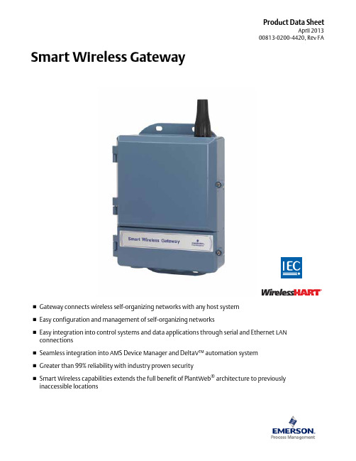
Product Data SheetApril 201300813-0200-4420, Rev FA⏹Gateway connects wireless self-organizing networks with any host system ⏹Easy configuration and management of self-organizing networks⏹Easy integration into control systems and data applications through serial and Ethernet LAN connections⏹Seamless integration into AMS Device Manager and DeltaV™ automation system ⏹Greater than 99% reliability with industry proven security⏹Smart Wireless capabilities extends the full benefit of PlantWeb ® architecture to previously inaccessible locationsSmart Wireless GatewaySmart Wireless Gateway April 2013Emerson Smart Wireless GatewayGain real-time process information with greater than 99% wireless data reliability⏹The Smart Wireless Gateway automatically manages wireless communications in constantly changing environments⏹Native integration with DeltaV and Ovation automation systems provides simple and fast commissioning for wireless field networks⏹Connect to data historians, legacy host systems, and other via a LAN applications through Ethernet, Modbus, Serial, OPC, EtherNet/IP, and HART outputsGuarantee system availability withredundant Smart Wireless Gateways⏹Never lose the wireless network with hot standby capabilityand automatic fault detection⏹Smart Wireless Gateways function as a single system,eliminating the need for duplicate host integration⏹One click configuration and plug-and-play architectureComplete wireless network configuration toolsprovided with each Gateway⏹The integrated web interface allows easy configuration of thewireless network and data integration without the need to installadditional software⏹Complimentary AMS Wireless Configurator software providesEmerson Device Dashboards to configure devices and viewdiagnostic dataDrag and Drop device provisioning enables asecure method to add new wireless devices tothe wireless field networkContentsEmerson’s Smart Wireless Solution .. . . . . . . . . page3IEC 62591 (WirelessHART®)... The Industry Standard page3Ordering Information . . . . . . . . . . . . . . . . . . . . . page4Accessories and Spare parts . . . . . . . . . . . . . . . . page5 Specifications . . . . . . . . . . . . . . . . . . . . . . . . . . . . page6 Product certifications . . . . . . . . . . . . . . . . . . . . . page8 Dimensional drawings . . . . . . . . . . . . . . . . . . . . . page9Smart Wireless Gateway April 2013Emerson’s Smart Wireless SolutionIEC 62591 (Wireless HART®)... The Industry StandardSelf-Organizing, Adaptive Mesh Routing⏹No wireless expertise required, network automatically finds the best communication paths⏹The self-organizing, self-healing network manages multiple communication paths for any given device. If an obstruction is introduced into the network, data will continue to flow because the device already has other established paths. The network will then lay in more communication paths as needed for that device.Reliable Wireless Architecture⏹Standard IEEE 802.15.4 radios⏹2.4 GHz ISM band sliced into 15 radio-channels⏹Time Synchronized Channel Hopping to avoid interference from other radios, WiFi, and EMC sources and increase reliability⏹Direct sequence spread spectrum (DSSS) technology delivers high reliability in challenging radio environment Emerson’s Smart WirelessSeamless Integration via a LAN to All Existing Host Systems ⏹Native integration into DeltaV and Ovation is transparent and seamless⏹Gateways interface with existing host systems via a LAN, using industry standard protocols including OPC, Modbus TCP/IP, Modbus RTU, and EtherNet/IPLayered Security Keeps Your Network Safe⏹Ensures that data transmissions are received only by the Smart Wireless Gateway⏹Network devices implement industry standard Encryption, Authentication, Verification, Anti-Jamming, and Key Management⏹Third party security verification including Achilles andFIPS197- User based login and enforced password strength. Password strength monitoring, user based log in, password reset requirements, automatic lockout, password expiration requirements. Based on guidelines from ISA99.03.03 standard approved level two. SmartPower™ Solutions⏹Optimized Emerson instrumentation, both hardware and software, to extend power module life⏹SmartPower technologies enable predictable power lifeSmart Wireless Gateway April 2013 Ordering InformationTable 1. Smart Wireless Gateway Ordering Information★ The Standard offering represents the most common options. The starred options (★) should be selected for best delivery.The Expanded offering is subject to additional delivery lead time.Model Product Description1420Smart Wireless GatewayPower InputStandard StandardA24 VDC Nominal (10.5-30 VDC)★Ethernet Communications - Physical ConnectionStandard Standard1(1)(2)Ethernet★2(3)(4)Dual Ethernet★Wireless Update Rate, Operating Frequency, and ProtocolStandard StandardA3User Configurable Update Rate, 2.4 GHz DSSS, Wireless HART★Serial Communication]Standard StandardN None★A(5)Modbus RTU via RS485★Ethernet Communication - Data ProtocolsStandard Standard2Webserver, Modbus TCP/IP, AMS Ready, HART-IP★4Webserver, Modbus TCP/IP, AMS Ready, HART-IP, OPC★5(6)DeltaV Ready★6(6)Ovation Ready ★8Webserver, EtherNet/IP, AMS Ready, HART-IP★9Webserver, EtherNet/IP, Modbus TCP/IP, AMS Ready, HART-IP★Options (Include with selected model number)Product CertificationsStandard StandardN5FM Division 2, Non-incendive★N6CSA Division 2, Non-incendive★N1ATEX Type n★ND ATEX Dust★N7IECEx Type n★NF IECEx Dust★KD FM & CSA Division 2, Non-incendive and ATEX Type n★N3China Type n★N4TIIS Type n★Redundancy OptionsStandard Standard RD(7)(8)(9)Gateway Redundancy★AdaptersStandard StandardJ1CM 20 Conduit Adapters★J2PG 13.5 Conduit Adapters★J33/4 NPT Conduit Adapters★Antenna Options(10)Standard Standard WL2Remote Antenna Kit, 50 ft. (15.2 m) cable, Lightning Arrestor★Smart Wireless GatewayApril 2013Accessories and Spare partsWL3Remote Antenna Kit, 20 ft. (6.1 m) and 30 ft. (9.1 m) cables, Lightning Arrestor ★WL4Remote Antenna Kit, 10 ft. (3.0 m) and 40 ft. (12.2 m) cables, Lightning Arrestor ★Expanded WN2(11)High-Gain, Remote Antenna Kit, 25 ft. (7.6m) cable, Lightning ArrestorTypical Model Number:1420A2A3 A 2 N5(1)Single active 10/100 baseT Ethernet port with RJ45 connector.(2)Additional ports disabled.(3)Dual active 10/100 baseT Ethernet ports with RJ45 connectors.(4)Multiple active ports have separate IP addresses, firewall isolation, and no packet forwarding.(5)Convertible to RS232 via adaptor, not included with Gateway.(6)Includes Webserver, Modbus TCP, AMS Ready, HART-IP, and OPC.(7)Requires the selection of Dual Ethernet option code 2.(8)Not available with DeltaV Ready option code 5.(9)Not available with EtherNet/IP option codes 8 and 9(10)The WL2, WL3, WL4, and WN2 options require minor assembly.(11)Not available in all countriesTable 1. Smart Wireless Gateway Ordering Information★ The Standard offering represents the most common options. The starred options (★) should be selected for best delivery.The Expanded offering is subject to additional delivery lead time. Table 2. AccessoriesItem DescriptionPart Number AMS® Wireless SNAP-ON™, 1 Gateway License 01420-1644-0001AMS Wireless SNAP-ON, 5 Gateway Licenses 01420-1644-0002AMS Wireless SNAP-ON, 10 Gateway Licenses 01420-1644-0003AMS Wireless SNAP-ON, 5-10 Upgrade Licenses 01420-1644-0004Serial Port HART Modem and Cables only 03095-5105-0001USB Port HART Modem and Cables only03095-5105-0002Table 3. Spare PartsItem DescriptionPart Number Spare Kit, WL2 Replacement (1), Remote Antenna, 50 ft. (15.2 m) Cable, and Lightning Arrestor01420-1615-0302Spare Kit, WL3 Replacement (1), Remote Antenna, 20/30 ft. (6.1/9.1 m) Cables, and Lightning Arrestor01420-1615-0303Spare Kit, WL4 Replacement (1), Remote Antenna, 10/40 ft. (3.0/12.2 m) Cables, and Lightning Arrestor 01420-1615-0304Spare Kit, WN2 Replacement (1), High Gain, Remote Antenna, 25 ft. (7.6 m) Cable, and Lightning Arrestor (2)01420-1615-0402(1)Can not upgrade from integral to remote antenna.(2)Not available in all countries.Smart Wireless GatewayApril 2013SpecificationsFunctional SpecificationsInput Power10.5 - 30 VDCCurrent DrawRadio Frequency Power Output from AntennaMaximum of 10 mW (10 dBm) EIRPMaximum of 40 mW (16 dBm) EIRP for WN2 High Gain optionEnvironmentalOperating Temperature Range: -40 to 158 °F (-40 to 70 °C)Operating Humidity Range: 10-90% relative humidityEMC PerformanceComplies with EN61326-1:2006.Antenna OptionsIntegrated Omnidirectional AntennaOptional remote mount Omnidirectional AntennaPhysical SpecificationsWeight10 lb (4.54 kg)Material of ConstructionHousingLow-copper aluminum, NEMA 4X PaintPolyurethaneCover GasketSilicone Rubber AntennaIntegrated Antenna: PBT/PC Remote Antenna: Fiber Glass CertificationsClass I Division 2 (U.S.)Equivalent WorldwideCommunication SpecificationsIsolated RS4852-wire communication link for Modbus RTU multidrop connectionsBaud rate: 57600, 38400, 19200, or 9600Protocol: Modbus RTUWiring: Single twisted shielded pair, 18 AWG. Wiring distance up to 4,000 ft. (1,524 m)Ethernet10/100base-TX Ethernet communication portProtocols: EtherNet/IP Modbus TCP, OPC, HART-IP, HTTPS (for Web Interface)Wiring: Cat5E shielded cable. Wiring distance 328 ft. (100 m).ModbusSupports Modbus RTU and Modbus TCP with 32-bit floating point values, integers, and scaled integers.Modbus Registers are user-specified.OPCOPC server supports OPC DA v2, v3EtherNet/IPSupports EtherNet/IP protocol with 32 bit Floating Point values and Integers.EtherNet/IP Assembly Input-Output instances are user configurable.EtherNet/IP specifications are managed and distributed by ODVA.Self-Organizing Network SpecificationsProtocolIEC 62591 (Wireless HART), 2.4 - 2.5 GHz DSSS.Maximum Network Size100 wireless devices @ 8 sec or higher.50 wireless devices @ 4 sec.25 wireless devices @ 2 sec.12 wireless devices @ 1 sec.Supported Device Update Rates1, 2, 4, 8, 16, 32 seconds or 1 - 60 minutesNetwork Size/Latency100 Devices: less than 10 sec.50 Devices: less than 5 sec.Data Reliability>99%C u r r e n t (m A )Operating Current Draw is based on 3.6 Watts average powerconsumption. Momentary startup Current Draw up to twice Operating Current Draw.Smart Wireless Gateway April 2013System Security SpecificationsEthernetSecure Sockets Layer (SSL)- enabled (default) TCP/IPcommunicationsSmart Wireless Gateway AccessRole-based Access Control (RBAC) including Administrator,Maintenance, Operator, and Executive. Administrator hascomplete control of the gateway and connections to hostsystems and the self-organizing network.Self-Organizing NetworkAES-128 Encrypted Wireless HART, including individual sessionkeys. Drag and Drop device provisioning, including unique joinkeys and white listing.Internal FirewallUser Configurable TCP ports for communications protocols,including Enable/Disable and user specified port numbers.Inspects both incoming and outgoing packets.Third Party CertificationWurldtech: Achilles Level 1 certified for network resiliency.National Institute of Standards and Technology (NIST):Advanced Encryption Standard (AES) Algorithm conforming toFederal Information Processing Standard Publication 197(FIPS-197)Smart Wireless Gateway April 2013 Product certificationsApproved Manufacturing LocationsRosemount Inc. – Chanhassen, Minnesota, USAEmerson Process Management GmbH & Co. - Karlstein, GermanyEmerson Process Management Asia Pacific Private Limited - SingaporeBeijing Rosemount Far East Instrument Co., Limited - Beijing, ChinaTelecommunication ComplianceAll wireless devices require certification to ensure that they adhere to regulations regarding the use of the RF spectrum. Nearly every country requires this type of product certification. Emerson is working with governmental agencies around the world to supply fully compliant products and remove the risk of violating country directives or laws governing wireless device usage.FCC and ICThis device complies with Part 15 of the FCC Rules. Operation is subject to the following conditions. This device may not cause harmful interference. This device must accept any interference received, including interference that may cause undesired operation. This device must be installed to ensure a minimum antenna separation distance of 20 cm from all persons. Ordinary Location Certification for FMAs standard, the Gateway has been examined and tested to determine that the design meets basic electrical, mechanical, and fire protection requirements by FM, a nationally recognized testing laboratory (NRTL) as accredited by the Federal Occupational Safety and Health Administration (OSHA).North American CertificationsN5FM Division 2, Non-IncendiveCertificate Number: 3028321Nonincendive for Class I, Division 2, Groups A, B, C, and D.Suitable for Class II, III, Division 1,Groups E, F, and G; Indoors/outdoor locations;Type 4XTemperature Code: T4 (-40 °C < T a < 60 °C)Canadian Standards Association (CSA)N6CSA Division 2, Non-IncendiveCertificate Number: 1849337Suitable for Class I, Division 2, Groups A, B, C, and D.Dust Ignition-proof for Class II, Groups E, F, and G;Suitable for Class III Hazardous Locations.;Install per Rosemount drawing 01420-1011.Temperature Code: T4 (-40 °C < T a < 60 °C)CSA Enclosure Type 4X European Union Directive InformationThe EC declaration of conformity for all applicable European directives for this product can be found on the Rosemount websiteat . A hard copy may be obtained by contacting your local sales representative.European CertificationN1ATEX Type nEx nA nL IIC T4 (-40 °C < T a< 60 °C)Special condition for safe use (X):The surface resistivity of the antenna is greater than onegigaohm. To avoid electrostatic charge build-up, it mustnot be rubbed or cleaned with solvents or a dry cloth.The Apparatus is not capable of withstanding the 500Vinsulation test required by Clause 9.4 of EN 60079-15:2005. This must be taken into account when installing the apparatus.ND ATEX DustCertificate Number: Baseefa 07ATEX0057Ex tD A 22 IP66 T135 (-40 °C < T a < 60 °C)Maximum working Voltage = 28 VN7IECEx Type nCertificate Number: IECEx BAS 07.0012XEx nA nL IIC T4 (-40 °C < T a < 60 °C)Maximum working voltage = 28 VSpecial condition for safe use (X):The surface resistivity of the antenna is greater than onegigaohm. To avoid electrostatic charge build-up, it mustnot be rubbed or cleaned with solvents or a dry cloth.The Apparatus is not capable of withstanding the 500 Vinsulation test required by Clause 9.4 of EN 60079-15:2005. This must be taken into account when installing the apparatus.NF IECEx DustCertification Number: IECEx BAS 07.0013Ex tD A22 IP66 T135 (-40 °C < T a < 60 °C)Maximum working voltage = 28 VCombinations of CertificationsKD Combination of N5, N6, and N1.Smart Wireless Gateway April 2013Dimensional drawingsFigure 1. Smart Wireless Gateway Dimensions are in inches (millimeters)Smart Wireless Gateway April 2013 Remote Antenna KitThe Remote Antenna kit includes sealant tape for remote antenna connection, as well as mounting brackets for the antenna, Lightning Arrestor, and the Smart Wireless Gateway.Lightning protection is included on all the options.*Note that the cables lengths on the remote antenna options WL3 and WL4 are interchangeable for installation convenience.Smart Wireless Gateway April 201311Standard Terms and Conditions of Sale can be found at \terms_of_sale The Emerson logo is a trade mark and service mark of Emerson Electric Co.Rosemount and the Rosemount logotype are registered trademarks of Rosemount Inc.PlantWeb is a registered trademark of one of the Emerson Process Management group of companies.HART and WirelessHART are registered trademarks of the HART Communication Foundation Modbus is a trademark of Modicon, Inc.All other marks are the property of their respective owners.© 2012 Rosemount Inc. All rights reserved.Emerson Process Management Rosemount Inc.8200 Market Boulevard Chanhassen, MN 55317 USA T (U.S.) 1-800-999-9307T (International) (952) 906-8888F (952) Emerson Process Management Blegistrasse 23P.O. Box 1046CH 6341 Baar Switzerland T +41 (0) 41 768 6111F +41 (0) 41 768 Emerson Process Management Asia Pacific Pte Ltd 1 Pandan Crescent Signapore 128461T +65 6777 8211F +65 6777 0947Service Support Hotline: +65 6770 8711Email:***************************.comSmart Wireless Gateway00813-0200-4420, Rev FAProduct Data Sheet April 2013Emerson Process Management Latin America 1300 Concord Terrace, Suite 400Sunrise Florida 33323 USA Tel + 1 954 846 5030。
艾莫迅wifi电缆手册说明书

AMSamotion帮助一百万家企业实现自动化智能制造WiFi无线PLC编程器使用手册(对应艾莫迅串口转TCP工具v6.0版本)[第一版]艾莫迅自动化科技(东莞)有限公司目录第一章WiFi电缆使用情景 (1)1-1.现场版WiFi电缆 (2)1-2.远程版WiFi电缆 (2)1-2-1.远程模式 (2)1-2-2.现场版AP模式 (3)1-2-3.现场版ST模式 (3)第二章艾莫迅串口转TCP工具应用 (4)2-1.软件的安装 (4)2-2.软件使用说明 (6)第三章指示灯及按键说明 (9)3-1.指示灯说明 (9)3-2.按键说明 (9)第四章WiFi电缆通讯步骤 (10)4-1.现场版WiFi电缆通讯 (10)4-2.远程版WiFi电缆通讯 (11)4-2-1.远程模式 (11)4-2-2.现场版AP模式 (15)4-2-3.现场版ST模式 (15)第五章通讯问题分析 (17)5-1.通用情况分析 (17)5-2.按通讯模式分析 (18)第六章应用拓展 (19)6-1.MODBUS开关量模块的无线控制 (19)6-2.组态王与PLC连接 (22)6-3.连接扩展 (24)6-4.定制开发 (24)附录 (25)第一章WiFi电缆使用情景通过WiFi电缆可对PLC/触摸屏等控制设备,以无线的方式现场短距离(空旷处理论30m)或远程,进行程序的上下载及监控,按不同功能分不同使用情景。
1-1.现场版WiFi电缆该电缆Model名称不带“-R”,WiFi名称数字部分不以0开头,上电PWR红灯常亮,仅此一种通讯模式,应用在现场范围30m内(理论值,受环境或干扰等因素可能降低)的电脑编程软件与PLC的通讯,电脑连接电缆的WiFi后无法上网1-2.远程版WiFi电缆Model名称带“-R”,WiFi名称数字部分以0开头,含有3种通讯模式:远程模式、现场版AP模式、现场版ST模式1-2-1.远程模式该模式为出厂通讯模式,当WiFi电缆和装有上位机的电脑均连外网时,即可在异地进行远程控制PLC。
Moxa OnCell G3470A-LTE Series 4G Ethernet IP 网关说明书

P/N: 1802034700012 *1802034700012*OnCell G3470A-LTE Series Quick Installation GuideMoxa OnCell SeriesVersion 2.2, January 2021Technical Support Contact Information/support2021 Moxa Inc. All rights reserved.OverviewThe OnCell G3470A-LTE is Moxa's 4G/Ethernet IP gateway that provides a higher cellular bandwidth and more reliable connection to your Ethernet network for cellular applications. With the integrated 4-port gigabit Ethernet switch and 4G LTE support, the OnCell G3470A-LTE offers a faster cellular connection with a lower total cost of ownership. To enhance reliability, a key for industrial users, the OnCell G3470A-LTE features isolation design for both power and antenna inputs. Coupled withhigh-level EMS and wide-temperature support, the OnCell G3470A-LTE provides the highest level of device stability in any rugged environment. In addition, with dual SIM and dual power-input features, the OnCellG3470A-LTE supports network redundancy to ensure an uninterrupted connectivity in your applications.Package ChecklistMoxa’s OnCell G3470A-LTE is shipped with the following items. If any of these items is missing or damaged, please contact your customer service representative for assistance.•OnCell G3470A-LTE• 1 GPS connector terminator• 2 2G/3G/4G omni-directional antennas, 2 dBi, SMA (male)• 5 plastic RJ45 protective caps for serial console and Ethernet ports •Quick installation guide (printed)•Warranty cardInstallation and ConfigurationBefore installing the OnCell G3470A-LTE, make sure that all items in the package checklist are in the box. In addition, you will need access to a notebook computer or PC equipped with an Ethernet port. The OnCellG3470A-LTE has a default IP address that you must use when connecting to the device for the first time.Step 1: Insert a SIM card and turn on the OnCell G3470A-LTE Insert one or two 2G/3G/4G SIM cards into the SIM slots located on the bottom of the OnCell G3470A-LTE. Then, turn on the OnCell G3470A-LTE by connecting a power terminal block to a DC power source (12 to 48 VDC).Step 2: Connect the OnCell G3470A-LTE to a notebook or PC Since the OnCell G3470A-LTE supports MDI/MDI-X auto-sensing, you can use either a straight-through cable or crossover cable to connect the OnCell G3470A-LTE to a computer. If the LED indicator on the OnCellG3470A-LTE’s LAN port lights up, it means a connection has been established.Step 3: Set up the computer’s IP addressSet an IP address on the same subnet as the OnCell G3470A-LTE. Since the OnCell G3470A-LTE’s default IP address is 192.168.127.254, and the subnet mask is 255.255.255.0, you should set the IP address of the computer to 192.168.127.xxx and subnet mask to 255.255.255.0.Step 4: Use the web-based manager to configure the OnCellG3470A-LTEOpen your computer’s web browser and type http://192.168.127.254 in the address field to access the homepage of the web-based management system. Before the homepage opens, you will need to enter the user name and password. For first-time configuration, enter the default user name and password and then click on the Login button: User name: adminPassword: moxaNOTE For the change to take effect, you must click Save Configuration to save the change, or Restart (clicking the Save and Restartbuttons will save all changes).Hardware Overview1. GPS antenna connector (femaleSMA)2. Terminal block (two digital inputand one digital relay) 3. Grounding screw (M5)4. Terminal block (PWR1 andPWR2)5. 2x2 MIMO antenna ports for LTE(female SMA)6. RS-232 serial console (RJ45)7. 10/100/1000 BaseT(X) Ethernetports (RJ45) 8. LED display9. DIN-rail mounting kit 10. Reset button11. Dual SIM – SIM1 12.Dual SIM – SIM2Device DimensionsDIN-Rail MountingDIN-Rail Kit Dimensions:Unit = mm (inch)The DIN-rail kit is attached to the back panel of the OnCell G3470A-LTE series. Mount the OnCell G3470A-LTE series on corrosion-free mounting rails that meet the EN 60715 standard.InstallationSTEP 1: Insert the upper lip ofthe DIN rail into the DIN-railmounting kit.STEP 2: Press the OnCellG3470A-LTE series towards theDIN rail until it snaps into place.RemovalSTEP 1: Pull down the latch onthe mounting kit using ascrewdriver.STEP 2: Slightly pull the OnCellG3470A-LTE forward.STEP 3: Lift up to remove theOnCell G3470A-LTE from theDIN railWall Mounting (optional)Wall-mount Kit Dimensions:Unit = mm (inch)For some applications, it may be more convenient to mount the OnCell G3470A-LTE to a wall, as illustrated below. STEP 1:Remove the aluminum DIN-rail attachment plate from the OnCellG3470A-LTE, and then attach the wall mount plates with M3 screws, as shown in the adjacent diagram.STEP 2:Mounting the OnCell G3470A-LTE to a wall requires 4 screws. Use the OnCell G3470A-LTE device, with wall mount plates attached as a guide, to mark the correct locations of the 4 screws. The heads of the screws should be less than 6.0 mm in diameter, and the shafts should be less than 3.5 mm in diameter, as shown in the figure at the right.NOTE Test the screw head and shank size by inserting the screw into one of the keyhole shaped apertures of the Wall Mounting Plates before it is screwed into the wall.STEP 3:Once the screws are fixed into the wall, insert the four screw heads through the large opening of the keyhole-shaped apertures, and then slide the OnCell G3470A-LTE downwards, as indicated in the accompanying diagram. Tighten the four screws for added stability.Wiring RequirementsYou should also pay attention to the following items:•Use separate paths to route wiring for power and devices. If power wiring and device wiring paths must cross, make sure the wires are perpendicular at the intersection point.NOTE: Do not run signal or communications wiring and power wiring in the same wire conduit. To avoid interference, wires with different signal characteristics should be routed separately.•You can use the type of signal transmitted through a wire to determine which wires should be kept separate. The rule of thumb is that wiring with similar electrical characteristics can be bundledtogether.•Keep input wiring and output wiring separate.•It is strongly advised that you label wiring to all devices in the system when necessary.Grounding the Moxa OnCell G3470A-LTEGrounding and wire routing help limit the effects of noise due to electromagnetic interference (EMI). Run the ground connection from the ground screw to the grounding surface prior to connecting devices.Wiring the Redundant Power InputsThe top two pairs of contacts of the 10-contact terminal block connector on the OnCell G3470A-LTE’s top panel are used for the OnCellG3470A-LTE’s two DC inputs. Top and front views of the terminal block connector are shown here.STEP 1: Insert the negative/positive DC wires Array into the V-/V+ terminals.STEP 2: To keep the DC wires from pulling loose,use a small flat-blade screwdriver to tighten thewire-clamp screws on the front of the terminalblock connector.STEP 3: Insert the plastic terminal blockconnector prongs into the terminal blockreceptor, which is located on the OnCellG3470A-LTE’s top panel.Wiring the Relay ContactThe OnCell G3470A-LTE has one relay output, which consists of the two contacts of the terminal block on the OnCell G3470A-LTE’s top panel. Refer to the Specification section for detailed electrical requirement. The relay contacts are used to indicate user-configured events. The two wires attached to the relay contacts form an open circuit when auser-configured event is triggered. If a user-configured event does not occur, the relay circuit will be closed.Wiring the Digital InputsThe OnCell G3470A-LTE has two sets of digital inputs—DI1 and DI2. Each DI comprises two contacts of the 6-pin terminal block connector on the OnCell G3470A-LTE’s top panel. Refer to the Specification section for detailed information on isolated digital input definition.Communication Connections10/100BaseT(X) Ethernet Port ConnectionThe 10/100BaseT(X) ports located on the OnCell G3470A-LTE’s front panel are used to connect to Ethernet-enabled devices.Below we show pinouts for both MDI (NIC-type) ports and MDI-X (HUB/Switch-type) ports. MDI Port Pinouts MDI-X Port Pinouts8-pin RJ45Pin Signal 1 Tx+ 2 Tx- 3 Rx+ 6Rx- Pin Signal 1 Rx+ 2 Rx- 3 Tx+ 6Tx-1000BaseT Ethernet Port Connection1000BaseT data is transmitted on differential TRD+/- signal pairs over copper wires.MDI/MDI-X Port PinoutsPin Signal 1 TRD(0)+ 2 TRD(0)- 3 TRD(1)+ 4 TRD(2)+ 5 TRD(2)- 6 TRD(1)- 7 TRD(3)+ 8TRD(3)-RS-232 ConnectionThe OnCell G3470A-LTE has one RS-232 (8-pin RJ45) console portlocated on the front panel. Use either an RJ45-to-DB9 or RJ45-to-DB25 cable to connect the Moxa OnCell G3470A-LTE’s console port to your PC’s COM port. You may then use a console terminal program to access the OnCell G3470A-LTE for console configuration. Console Pinouts for 10-pin or 8-pin RJ45 10-PinDescription8-Pin 1 – 2 DSR 1 3 RTS 2 4 GND 3 5 TxD 4 6 RxD 5 7 DCD 6 8 CTS 7 9 DTR 8 10–NOTE The pin numbers for both 8-pin and 10-pin RJ45 connectors (and ports) are typically not labeled on the connector (or port). Referto the Pinout diagram above to see how RJ45 pins are numbered.LED IndicatorsThe front panel of the Moxa OnCell G3470A-LTE contains several LED indicators. The function of each LED is described in the table below. LED Color State DescriptionPWR1 Green On Power is being supplied from power input 1. PWR2 Green On Power is being supplied from power input 2.READY Green OnSystem startup is complete and the systemis operating.BlinkingDevice has been located by the OnCellSearch Utility.Off Power is off, or the system is booting up.FAULT Red OnSystem configuration error or a relay eventhas occurred.Blinking IP address conflict.Off Power is off, or there is no error condition.CELLULARSIGNAL (3 LEDs) Green OnNumber of LEDs to indicate cellular signallevel when registered to a base station.Signal LED 1: 0 < RSSI ≤ 12Signal LED 2: 12 < RSSI ≤ 20Signal LED 3: 20 < RSSI ≤ 31SIM1 Amber On/Off SIM 1 is active or inactive.Blinking SIM 1 is not inserted or PIN code is incorrect.SIM2 Amber On/Off SIM 2 is active or inactive.Blinking SIM 2 is not inserted or PIN code is incorrect.2G Amber On Registered to a base station with cellular connection in GPRS or EDGE mode.3G Amber On Registered to a base station with cellular connection in UMTS or HSPA mode.4G Amber On Registered to a base station with cellular connection in LTE mode.GPS Green On GPS has been located.BlinkingLocating GPS or less than four satellites havebeen located.Off GPS has not been located.1000M Green On 1000Mbps link is active.Blinking Data is being transmitted at 1000Mbps. Off 1000Mbps link is inactive.10/100M Amber On 10/100Mbps link is active.Blinking Data is being transmitted at 10/100Mbps. Off 10/100Mbps link is inactive.SpecificationsCellular SpecificationStandards GSM/GPRS/EDGE/UMTS/HSPA/LTEBand Options OnCell G3470A-LTE-EU: B1 (2100 MHz)/B3 (1800MHz)/B7 (2600 MHz)/B8 (900 MHz)/B20 (800 MHz)OnCell G3470A-LTE-US: B2 (1900 MHz)/B4(AWS)/B5 (850 MHz)/B13 (700 MHz)/B17 (700MHz)/B25 (1900 MHz)OnCell G3470A-LTE-EU: UMTS/HSPA2100/1900/850/800/900 MHzOnCell G3470A-LTE-US: UMTS/HSPA2100/1900/AWS/850/900 MHzQuad-band GSM/GPRS/EDGE 850/900/1800/1900MHzLTE Data Rate Category 3Downlink: 100 Mbps (20 MHz bandwidth), 50 Mbps(10 MHz bandwidth)Uplink: 50 Mbps (20 MHz bandwidth), 25 Mbps (10MHz bandwidth)HSPA Data Rate Downlink: Up to 42 Mbps (category 24)Uplink: Up to 5.76 Mbps (category 6)GPRS Data Rate Downlink/Uplink: 236 kbpsInterfaceCellular Antenna Connectors 2 SMA (female), MIMO for LTE, antenna diversity for WCDMASIM Slots Dual SIM card supportGNSS 1 SMA (female), GPS: 1575.42 MHz, GLONASS:1602 MHzEthernet 4, 10/100/1000 Mbps auto negotiation speed, F/Hduplex mode and auto MDI/MDI-X connection(RJ45-type)Serial Console Port 1, RS-232 (RJ45-type)LED Indicators PWR1, PWR2, READY, FAULT, CELLULAR SIGNAL,SIM1, SIM2, 2G, 3G, 4G, GPSAlarm Contact 1 relay output with current carrying capacity of 1 A@ 24 VDCDigital Inputs 2 electrically isolated inputs+13 to +30 V for state “1”+3 to -30 V for state “0”Max. input current: 8 mAGround Screw M5Reset Button Power Reset/Factory Default ResetSoftware SpecificationNetwork Protocol ICMP, TCP/IP, UDP, DHCP, Telnet, DNS, SNMP,HTTP, HTTPS, SMTP, SNTP, ARPRouting/Firewall NAT, Port Forwarding, IP/MAC/Port FilteringVPN Max. Tunnel Number: 5 (Responder/Initiator)IPSec (DES, 3DES, AES, MD5, SHA-1, DH2, DH5),PSK/X.509/RSAManagement Options Remote SMS Control, SNMPv1/v2c/v3, Web/Telnet/Serial ConsoleOthers DDNSSoftware Specification (Moxa Proprietary)GuaranLink 3-tier heart-beat for reliable and persistent cellularconnectivityOnCell Central Management Large scale centralized device management over private cellular IP addressesSearch Utility Simple device configuration and managementutilityPhysical CharacteristicsHousing Metal casing for high EMC-level, providing IP30protectionMounting DIN-rail (default) or wall-mount (optional) Weight 1300 gDimension 67 x 90.5 x 124 mm (2.6 x 3.52 x 4.83 inch) Installation DIN-Rail mounting, wall mounting (with optionalkit)Environmental LimitsOperating Temperature Standard Models: -30 to 55°C (-22 to 131°F) Wide Temp. Models: -30 to 70°C (-22 to 158°F) Storage Temperature-40 to 75°C (-40 to 167°F)Ambient Relative Humidity5 to 95% (30°C, non-condensing)Power RequirementsInput Voltage 12 to 48 VDC, redundant dual DC power inputs Connector 4-pin removeable terminal blockPower Consumption 9.6 W (12 V/0.78 A to 48 V/0.2 A)Reverse Polarity ProtectionPresentStandards and CertificationsSafety OnCell G3470A-LTE-US: UL 60950-1EMI OnCell G3470A-LTE-US: FCC Part 15 Subpart B EMS OnCell G3470A-LTE-EU: EN 61000-6-2/-4 Radio OnCell G3470A-LTE-US: FCC ID N7NMC7355OnCell G3470A-LTE-EU: EN 301 489-1, EN 301489-7, EN 301 511/4ReliabilityMTBF 327326 hoursWarrantyWarranty Period 5 yearsDetails See /support/warranty.aspx。
艾默生UPS用户手册

警告
大对地漏电流:在接入输入电源前(包括交流市电和电池),请务必可靠接地。 设备的接地必须符合当地电气规程。
UPS 系统前级配电保护设备的选择必须符合当地电气规程。
警告
警告 UPS 内部保险损坏,更换时必须使用相同电气参数的保险,并由专业人员操作。
小心
本设备安装有射频干扰(RFI)滤波器。 对地漏电流在 3.5 mA~1000mA 之间。 在选择瞬变漏电流断路器(RCCB)或其它漏电检测仪器(RCD)时应考虑设备启动时可能出现的瞬态和稳态对地漏电流。 必须选择对单向直流脉冲(A 级)和瞬态电流脉冲不敏感的 RCCB。 请注意负载的对地漏电流也将流过 RCCB 或 RCD。
型号 UF-BCB500/0500-03、UF-BCB300/0500-03 TMP12Z UF-SNMP114 UF-MODBUS110 UF-DRY210 UF-DRYCONTACTOR UF-BATTLEAK
UF-DRY110 SPD24Z-SPD-24
-
安全事项
遵守及标准
本设备符合以下 UPS 参考标准: z IEC60950-1,IEC62040-1-1 使用操作区一般安全要求 z IEC/EN62040-2 EMC 要求 z IEC62040-3 性能要求和测试方法
1.1 特点.........................................................................................................................................................................................1 1.2 设计思想.................................................................................................................................................................................1
- 1、下载文档前请自行甄别文档内容的完整性,平台不提供额外的编辑、内容补充、找答案等附加服务。
- 2、"仅部分预览"的文档,不可在线预览部分如存在完整性等问题,可反馈申请退款(可完整预览的文档不适用该条件!)。
- 3、如文档侵犯您的权益,请联系客服反馈,我们会尽快为您处理(人工客服工作时间:9:00-18:30)。
TOC-1
Smart Wireless Gateway
Reference Manual
00809-0200-4420, Rev CA August 2010
APPENDIX A Product Specifications
APPENDIX B Product Certifications
APPENDIX C Delta V Ready
PlantWeb is a registered trademark of one of the Emerson Process Management group of companies. Modbus is a registered trademark of Schneider Automation, Inc. All other marks are the property of their respective owners.
SECTION 3 Mounting and Connection
SECTION 4 Software Setup
SECTION 5 Host Integration
SECTION 6 Troubleshooting SECTION 7 Glossary
Safety Messages . . . . . . . . . . . . . . . . . . . . . . . . . . . . . . . . . . . . . . . . 1-1 Introduction . . . . . . . . . . . . . . . . . . . . . . . . . . . . . . . . . . . . . . . . . . . . . 1-1 Manual . . . . . . . . . . . . . . . . . . . . . . . . . . . . . . . . . . . . . . . . . . . . . . . . 1-2 Service Support . . . . . . . . . . . . . . . . . . . . . . . . . . . . . . . . . . . . . . . . . 1-3 Return of Materials . . . . . . . . . . . . . . . . . . . . . . . . . . . . . . . . . . . . . . . 1-3 Product Recycling/Disposal . . . . . . . . . . . . . . . . . . . . . . . . . . . . . . . . 1-3
Overview. . . . . . . . . . . . . . . . . . . . . . . . . . . . . . . . . . . . . . . . . . . . . . . 5-1 Network Architecture . . . . . . . . . . . . . . . . . . . . . . . . . . . . . . . . . . . . . 5-1 Internal Firewall . . . . . . . . . . . . . . . . . . . . . . . . . . . . . . . . . . . . . . . . . 5-3 Modbus . . . . . . . . . . . . . . . . . . . . . . . . . . . . . . . . . . . . . . . . . . . . . . . . 5-4
NOTICE
Read this manual before working with the product. For personal and system safety, and for optimum product performance, make sure you thoroughly understand the contents before installing, using, or maintaining this product. Within the United States, Emerson Process Management has two toll-free assistance numbers: Global Service Center Software and Integration Support 1-800-833-8314 (United States) +63-2-702-1111 (International) Customer Central Technical support, quoting, and order-related questions. 1-800-999-9307 (7:00 am to 7:00 pm CST) North American Response Center Equipment service needs. 1-800-654-7768 (24 hours—includes Canada) Outside of the United States, contact your local Emerson Process Management representative.
Overview. . . . . . . . . . . . . . . . . . . . . . . . . . . . . . . . . . . . . . . . . . . . . . . 4-1 System Requirements . . . . . . . . . . . . . . . . . . . . . . . . . . . . . . . . . . . . 4-1 Software Installation . . . . . . . . . . . . . . . . . . . . . . . . . . . . . . . . . . . . . . 4-2 Security Setup Utility. . . . . . . . . . . . . . . . . . . . . . . . . . . . . . . . . . . . . . 4-2 AMS Wireless Configurator . . . . . . . . . . . . . . . . . . . . . . . . . . . . . . . . 4-4 Licensing and Credits . . . . . . . . . . . . . . . . . . . . . . . . . . . . . . . . . . . . . 4-6
Reference Manual
00809-0200-4420, Rev CA August 2010
Smart Wireless Gateway
Table oLeabharlann ContentsSECTION 1 Overview
SECTION 2 Initial Connection
Functional Specifications . . . . . . . . . . . . . . . . . . . . . . . . . . . . . . . . . . A-1 Physical Specifications . . . . . . . . . . . . . . . . . . . . . . . . . . . . . . . . . . . . A-1 Communication Specifications . . . . . . . . . . . . . . . . . . . . . . . . . . . . . . A-2 Self-Organizing Network Specifications . . . . . . . . . . . . . . . . . . . . . . . A-2 System Security Specifications. . . . . . . . . . . . . . . . . . . . . . . . . . . . . . A-3 Dimensional Drawings . . . . . . . . . . . . . . . . . . . . . . . . . . . . . . . . . . . . A-4 Ordering Information. . . . . . . . . . . . . . . . . . . . . . . . . . . . . . . . . . . . . . A-6 Accessories and Spare Parts . . . . . . . . . . . . . . . . . . . . . . . . . . . . . . . A-7
Reference Manual
00809-0200-4420, Rev CA August 2010
Smart Wireless Gateway