GM 1927-04 APQP Manual
GP-12
早期生产控制 GP - 12注意:GP-12“早期生产控制”(GM-1920)已作为通用公司PPAP程序的特别部分。
具体请参考全球供方质量手册(GM1927)之APQP14。
1.0范围:GP-12适用于生产前、生产中、服务以及一些零件的附加要求,其中包括:●对PPAP的要求●当作GM的要求为客户提供方便2.0定义与目的:GP-12要求有一个试生产控制计划,该计划对供方量产控制计划具有促进作用,可以增加其信任度以确保所有对GM发运的产品都能满足GM的要求。
同时,试生产控制计划将用于验证量产控制计划。
并且试生产控制计划必须考虑所有已知的零件严重问题以及PPAP中所识别的潜在问题。
GP-12的目的:●验证供方的量产控制计划。
●在关键时期保证在装配、生产线和零件存放仓库无不合格品。
●在开始生产、加快生产时,生产过程更改,或者三个月(或者更长)未进行生产后,供方对过程控制进行验证,且必须文件化。
●确保任何可能发生的质量问题能在供方很快得到识别与纠正。
●引起供方最高管理者的关注。
3.0供方责任:供方必须确保:A.验证过程:验证过程需包括以下几点:1.指定责任人以确保验证过程得以执行。
2.由客户规定开始执行GP-12的日期,结束标准以及结束日期。
3.GP-12控制区必须是一个单独区域,与一般生产过程分开,并且为最后一道工序。
另外,可以在每道工序后增加控制以使效果更佳,但是,必须得到客户或供方质量工程师(SQE)的批准。
4.GP-12控制区的附加检验、测试和尺寸检测的确定是以产品关键特性、零件质量特性、高风险系数和/或产品开发过程中所产生的问题为基础。
5.对在GP-12控制区进行标准作业的相关人员实施培训。
6.针对每个问题点必须制定一个反应计划。
7.各级管理人员(包括现场领导)需对GP-12进行过程审核以确保与试生产控制计划相符合。
8.过程验证必须包括分承包商(即二级供应商)。
B.计划实施:试生产控制计划的实施包括附加控制、检验、审核和测试,将促进量产控制计划以确保加工过程的一致性与可能性。
GM_1927-01_Project_Plan
Initial Control Plan Review
Control Plan Follow Up
GP12 & Production Control Plans
GP12 & Production Control Plans Updates GP12 Audit GM1927-33 (Compliance) Dimensional Report GM1927-32 GM1411 (if not full)
QSB or Greenfield Facility implementation Follow Up
QSB Audit GM1927-30 (Compliance) or Greenfield Assessment Checklist GM1927-31 Flow Chart Flow Chart Updates
7 Flow Chart 8 DFMEA
Flow Chart Follow Up
Initial -TR
Initial DFMEA Review
KCDS GMW15049 Workshop GD&T Workshop
DFMEA Follow Up
DRBFM for any design change
DFMEA Update
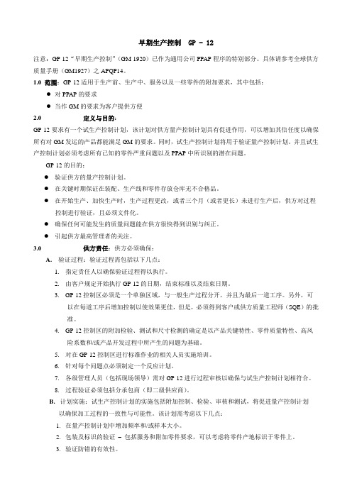
Global APQP Project Plan
GM GVDP 5.0 33/20 Global APQP Tasks -165 Commodity Key 1 Stakeholders Mtg 2 Technical Reviews 3 Supplier Eligibility
Pre-Sourcing Pre-Sourcing Pre-Sourcing Tiered Supplier APQP Assessment GM1927-7 CVER P Release -110 SVER P Release -98 IVER P Release -83
APQP GP-12早期生产遏制程序
SUPPLIER RESPONSIBILITY: The supplier shall:供应商职责:供应商必须
•在重要时期防止我们的装配和制造中心及服务件仓库出现质量问 题
•Document the supplier‘s efforts to verify control of its processes during start-up, acceleration, after revisions to the manufacturing process, or when manufacturing runs are separated by 3 months or more记 录 供 应 商 在 开 始 生 产 、 加 速 生 产过 程 、生产过程 变更后或生产停产三个月或以上时 , 为 控 制 其 过程 所 做 的努 力
1 Increased frequency/sample size as stated in the Production Control Plan. 1在产品控制计划中增加的频次和样品容量
2 Verification of packaging and label requirements – including service and accessory part requirements, which may include country of origin labels on parts. 2确认包装和标签的要求包括服务件和附件的要求,可能包括产品原产国标签 3 Verification of the effectiveness of error proofing. 确认防错的有效性
APQPGateReview
5
GM Global APQP 理解
▶Global APQP 17 Task
Task 1: 产品定点策略会 Task 2: 技术评 Task 3:APQP风险评估与定点 Task 4: 供应商项目评审(GR) Task 5:进度表/问题清单 Task 6:QSB Task 7:过程流程图 Task 8: DFMEA Task 9:设计评审(D/R) Task 10:量具、工装与设备评审 Task 11: Gage Development Process Task 12: PFMEA Task 13: Control Plan Task 14: GP-12 Task 15: PPAP Task 16: Run @ Rate Task 17:经验教训
Run@Rate (最终期限 -1)
阶段评审 关 键 交付物
APQP 供应商状态工作表GM1927-34(SGM) 启动会议检查清单 GM1927-14(SGM)
分供方状态更新 GM1927-25
验证计划 - A/D/V P&R GM1829
4
阶段评审交付物 (必须评估信息有效性 )
售后数据/下降计划 GM和供应商项目联系 清单GM1927-17(SGM) 分供方管理计划草案
好 的 开 始 是 成 功 的 一 半, 从 一 开 始 做 好 正 确 的 事 情 …
3
GM Global APQP 理解
全球APQP项目计划(整车项目)
= Repeat previous activity
GM GVDP 5.0 33/20 全球APQP任务
概 念 整车 工程释放 (CVER) 产 品 释放
▶ Production Control Plan
GM 1927-16b Aluminum Extrusion Process Audit 中英文
19
20
21
22
3 of 9
Raw Materials(原材料)
2 of 9
GM Process Audit
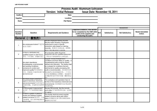
Process Audit: Aluminum Extrusion Version: Initial Release Issue Date: November 18, 2011
Auditor: Supplier: Duns: Date: Location: Part Name:
18 Is the die condition verified after or before each production run ? 是否模具的状态被证实的在批产 前或后? Is material (billets) certified?是否 材料(坯料)被证实的? Is the billet hold time controlled and recorded (prior to extrusion process) ?是否对坯料保存时间 控制及记录(挤出工序前)? Is the billet temp controlled and recorded (prior to extrusion) ?是 否对坯料温度控制与记录(挤出 工序前)? Is the extrusion die identified?是 否挤压模具可被识别的? Review die PM, inspection records (die or product) 审查模具生产管理,检验记录 (模具或产品)。 Review chemistry, dia & length。审查化 学过程,直径和长度。 Verify specified max & min time in the preheat oven. How is it controlled ?核查 特定的最大与最小的烤箱预热时间。是 如何控制的? Verify specified max & min temp. How is it controlled ?核查特定的最大和最小温度 值,是如何控制的? Review the die number, revision #, process sheet。核查模具编号、版本、 流程卡。
APQP培训资料完整版ppt经典培训教材

N/A
正式物流订单
Salable不可销售车(中批量)
MVBS
Manufacturing Validation Build Salable可销 PPAP或者 正式物流订单
售车(大批量)
TWO
PPQP: Pre-Production Part Quality Process 試制零件質量控制流程
正式生产场地 正式生产场地
3
1.1什么是APQP 方法??
先期的产品质量计划 (APQP: Advanced Product Quality Plan)是一个结构性的方法,用来确定和制定确保某产品使顾客 满意所需的步骤。这是一套从产品概念至产品寿命终止,通过 产品质量先期计划和控制计划以制定各阶段作业方式与质量活 动,以确保产品在开发原形样品(Prototype)、试生产 (Prelaunch)及量产 (Mass Production)等阶段的管理活动有效运作 ,并识别此过程中的所有变异及减少变异的方法。
目的: 帮助我们早期发现问题,避免不合格的发生或顾客抱怨 的发生。
4
1.2为什么需要APQP??
它指导按时间进度(milestone)有条不紊地进行产品和过 程的开发,它是产品质量的诞生过程,促进对问题的早期识 别,并体现以预防为主的特征。
建立一套完善的适用于每个项目的设计开发体系,使公司 产品开发充分满足顾客的要求从而提高公司的利润。
6
7
QPNI
VFF
EM交付
8
QPNI
PVS 2 TP
9
QPNI
OS 2 TP
10
APQP
造车节 点
节点描述
文件 订单方式
造车区域
IV OTS MC1
GM-1925
ForewordThe GM Fixture Standards for Suppliers of Production Material was developed to establish common GM supplier PPAP checking fixture standards worldwide. Previously, fixture standards existed at the divisional or unit level only.In 1996, a development team was formed which included representatives from GM Truck, Mid/Lux, and the Small Car Group. In addition, the development process included collaboration with Saturn, GM Powertrain, and GM Canada Group.Table of ContentsSubject Page Revision Information 3 I. Preface 4 II. Part Supplier Responsibilities 5 III. Design Concept 6 IV. Concept Approval 7 V. Design Requirements 7 VI. Build Requirements 10 VII. Certification Requirements 12 VIII. Gage Repeatability and Reproducibility 13 RequirementsIX. Maintenance Requirements 14 X. Glossary 15 XI. Appendix A 16 XII. Appendix B 17Revision InformationVersion Date Section Item1.0 12/97 Release Revisions, if any to this document will be documented on this page as shown. This listwill be extended as new revisions are made, retaining the old entries for documentation purposes. The versions will sequence 1.0, 2.0, 3.0, etc. for revisions. The section and item changed can be referenced to quickly locate any changes made from version toversion.This manual supersedes the following documents:∙Truck & Bus Checking Fixture/Gage Standards (T&B 391), December, 1989.∙MID/LUX Part Fixturing Design/Build Standards, April, 1996.GM Fixture StandardsI. PrefaceA. IntroductionIn accordance with The Automotive Industry Action Group (AIAG), TheAdvanced Product Quality Planning (APQP) Manual, and The ProductionPart Approval Process (PPAP), part suppliers will obtain fixtures, if andwhen required, to monitor their product as part of their quality plan.Production part suppliers shall utilize this manual in addition to their ownstandards and requirements when quoting, designing, and buildingfixtures for General Motors purchased parts.The GM Supplier Quality Engineer (SQE) may modify the standards to thegaging situation, if the engineer deems necessary, and then only withsupporting documentation.B. ScopeThe GM Fixture Standards summarize the minimum requirements thatapply to all GM supplier PPAP checking fixtures worldwide.Although this manual exists to provide a uniform process for theprocurement of PPAP checking fixtures, suppliers are encouraged toincorporate these standards into their in-process or sub-assembly gaging.In addition to these standards, the following manuals can be utilized forreference, where applicable:The GM P.E.D.-114 Checking Fixture/Gage Standards ManualThe manual provides standards for sheet metal body componentsand assembly fixtures.The NAO Fixture Standards for Suppliers of Pre-Production Material(Ref. NAO #0042)The manual provides body-in-white sheet metal part suppliers andmajor plastic part suppliers with guidelines for designing, building,and evaluating prototype inspection fixtures.II. Part Supplier ResponsibilitiesA. When fixtures are required, the part supplier is directly responsible for allelements of the fixture procurement process. In addition, the part suppliershall document all relevant activity. Due to the varying complexity ofcomponent parts covered under this document, the supplier must contactthe procuring unit to determine the appropriate extent of the GM SQE’sinvolvement.B. The Supplier shall ensure that the following apply to all fixtures:1. Are procured in a timely manner to meet program timing objectives,including GP-11 where applicable.2. Agree with functional part usage.3. Comply with part Geometric Dimensioning and Tolerancing (GD&T)by honoring the datum scheme.4. Include the measurement of Key Product Characteristics (KPC’s)where applicable.5. Include, when required, variable data collection devices that arecapable of satisfying the AIAG Measurement Systems Analysis(MSA) requirements.6. Include the ability to discriminate part variation from nominal.C. In accordance with QS-9000 Element 4.11, the supplier shall establishand maintain documented procedures for measuring equipment control.This documentation should include:1. A dimensional inspection report. The use of a CoordinateMeasuring Machine (CMM) is preferred.2. Documentation of engineering changes.3. A Gage Repeatability and Reproducibility study.4. A fixture design print.The supplier shall maintain the change columns of both the fixture designand the fixture. The change column shall reflect the latest productiondesign level whether the fixture has been affected or not (see Section VI,Item P).The supplier is expected to resolve design problems in a timely manner.The design and construction source is responsible for immediatenotification that a problem exists. Any revision that changes the originalfixture cost must be approved by GM Purchasing.III. Design ConceptA. Prior to starting a fixture design, a preliminary design concept meetingshould be held. Core members expected to participate include thefollowing: the supplier fixture engineer, the fixture design/constructionsource representative, and the GM SQE. Other members may include:the GM Release Engineer, the Dimensional Engineering Engineer, amanufacturing plant representative, and the GM Purchasingrepresentative.B. The design concept shall consist of a sketch and a written description ofthe fixture with sufficient detail in order that the fixture design process canproceed. The design concept should not be as detailed as a completedesign, but it should include the following information:1. The part position in relationship to the fixture base. Body positionis preferred, however, other orientations may be appropriate tomaximize part/gage usage (e.g. first-use position). 90 degreeincrements should be used when deviating from body position.2. A datum scheme consistent with the specified GeometricDimensioning and Tolerancing.3. Details and devices for supporting the part.4. Proposed clamping techniques.5. Details and devices for inspection of features such as:* Key Product Characteristics* Feature lines* Functional holes* Historic areas of high process variability6. Acceptable construction materials based on fixture usage andenvironment to ensure functionality, repeatability, andreproducibility throughout the length of the part program.7. Mating or adjacent part representations or features whereapplicable.C. Operator ergonomics, part loading and unloading, and accessibility forCMM inspection and Statistical Process Control (SPC) data collectionshould be considered in the Design Concept. Operator usage should alsobe considered when fixtures are required on vehicle programs that areglobal in scope (Language for region of use).D. The X,Y,Z location(s) on product features where SPC data will becollected to monitor KPC’s shall be reviewed and approved by the GMSQE. Whenever possible, KPC’s on mating parts should be coordinatedtogether to obtain a one-to-one relationship in data results.IV. Concept ApprovalIf Concept Approval is required by the procuring division, the part supplier shallobtain Concept Approval by the GM SQE prior to initiating the fixture designprocess (see Section II, Item A).Any change which may occur during the fixture procurement process that hassignificant impact on the original concept should be reviewed with the GM SQE. V. Design RequirementsA. The Design source shall refer to the concept sketch and the writtendescription as the controlling expression of the design.B. All drawings should be full-size, and accurately represent the dimensionsshown. In addition:1. Details shall be complete in all views and must be dimensioned tomachined surfaces and/or body and/or work lines.2. All section views shall be referenced by section and sheet numbercorresponding to the call-out on the gage design drawing. (i.e.,SEC C-C or 100.0; Sheet 1).3. Drawings should include a representation of the part (phantom)shown in its gaging position. Line weight must be sufficient forreproduction.4. The stock list shall include all stock sizes, and must identifystandard items by supplier name and full catalog number.5. Fixture design details should be drawn separately from the fixtureassembly only when needed for build clarification.6. All dimensions should be in metric, however, the stock list maycontain items in standard English dimensions.7. Stock items (i.e., angle brackets, risers, hinge drops, slides, screws,dowels, etc.) should consist of standard commercially availablematerials whenever possible.8. Fixture designs may be generated utilizing either Computer AidedDesign software or manually drawn on 1.5 Mylar film.C. The environment in which the gage is to be used should be consideredwhen choosing the material, slides, pins, clamps, etc. to ensure that theyremain functional throughout the product program.D. The datum scheme shall be applied to the fixture design drawing and thegage. The general concept is to locate the part in three dimensions byuse of datum locators referred to as “primary,” “secondary,” and “tertiary”datums.E. Datum Hole Locator(s):1. Gage pins that are not used as datum locators shall not restrict partmovement in any direction not specified as a datum. This situationmay be addressed by utilizing a sliding or movable detail allowingmovement in the non-datum direction. The slide, however, shouldbe a precision slide in that it must not affect the specified locationtolerance for the datum locator.2. For attribute gaging to take full advantage of allowable tolerances,the part should be checked in the gage with datum locators madeat Maximum Material Condition (MMC). This pin may be attachedto a slide or movable detail to allow free movement in the non-datum direction.3. For variable gaging all datum locators are Regardless of FeatureSize (RFS), and shall be used to positively locate the part in thedatum direction specified. One way to accomplish this is to use aspring-loaded tapered pin. This pin may be attached to a slide ormovable detail to allow free movement in the non-datum direction.F. Datums that are positioned directly adjacent to a spotweld, seam weld orparting line shall be brought to the attention of the GM SQE. If the datumcannot be re-located, clearance shall be provided on the fixture detail tofacilitate gage R & R.G. Normal build practice notes, (i.e., dimensions for cable attachments orscrews and dowels) are not necessary on the fixture design.H. All details utilized for part inspection including check pin sizes shall beidentified on the gage design. In addition, all removable andinterchangeable details shall be identified including their associatedfunction. The use of color coding details has proven to be an effectivetechnique in communicating the use of multiple model applications on the same gage or fixture ( i.e., Buick, Chev.,Vectra, Omega, etc.).Interchangeable details require the following:1. Hardened steel bushings for locator pins.2. Permanently attached hand knobs.I. Cut lines (i.e. body grid lines) in bases larger than 48” should beconsidered when utilizing height gages for part evaluation.J. To ensure consistent dimensional checking from construction to certification, the design should include documented start points for basealignment on a coordinate measuring device. These points can be tooling balls, pins, blocks, or some other clearly identified zones on the base.K. The gage design shall be such that no detail overhangs the gage base when the detail is in any position.L. Showing redundant or right to left symmetry is not necessary on fixture designs. Wherever practical include only unique, one sided detailinformation with a “Symmetrical About C/L Except as Shown” note.M. All part information including math data used in the design and required for fixture construction must be identified on the fixture design.N. All changes to the fixture design shall be alpha-numerically indicated in a change notice block affixed to the upper right hand corner of sheet oneand ballooned throughout the design where applicable. A brief changedescription referencing the appropriate Engineering Work Order (EWO) or applicable engineering change number should be identified with eachchange event.O. Operator instructions and/or a sequence of operations on the use of the fixture shall be shown on the completed design. The use of multilingualoperator instructions should be considered where applicable.P. The production part supplier shall review the finished design with the design source and provide the fixture/gage design to the GM SQE whenrequested. The use of the Checking Fixture Design Check List isrecommended (ref. Appendix A).VI. Build RequirementsA. The construction source shall treat the design as the controllingexpression of gage construction.B. Whenever possible, all fixtures should be built to math data. Part designdrawing information should be utilized when math data is not available.1. Die models, die model dupes, cutter tapes, etc. if available areconstruction aids only.2. Surfaces of gages taken from any die models, die model dupes,etc. are to be completely checked and certified to engineering dataper above specifications.C. All datums, inspection details, clamps, and interchangeable details shallbe identified on the fixture in a visible location as shown on the design.D. For attribute checking details, the use of scribe lines, part outlines, andtrim lines are an acceptable method for part evaluation. An additionalalternative is to scribe a “Max/Min” line, capturing the theoretical nominaltrim line.E. For variable data collection devices, a standard zero block, with bushing,is to be mounted to the fixture base. The set-up dimension should be anominal value, i.e., 50.00 mm.F. Operator instructions and/or a sequence of operations on the use of thefixture shall be securely affixed to the gage. The use of multilingualoperator instructions should be considered where applicable.These must be the same instructions as shown on the fixture design(see Section V, item O).G. The use of eye-bolts for fixtures over 50 pounds is recommended.H. All weldments shall be stress relieved, unless prior approval is obtained bythe GM SQE.I. All loose and interchangeable details such as hand knobs and check pinsshall be permanently attached to the fixture. The use of self storing(restrained) devices or recoil type cables are recommended.J. The use of shims or shim stock is not an acceptable practice in the construction of GM checking fixtures.K. When templates are utilized, ¼” aluminum stock is an acceptable choice for template construction.L. All non-check fixture surfaces shall be painted medium blue.M. Any steel non-check details susceptible to oxidation should be coated in such a manner as to provide long term protection based on usage,environment, etc. Wipe-on solutions that are removed by normal handling of the details are not recommended.N. All check pins shall be manufactured from an acceptable material and hardness to ensure durability and functionality throughout the life of thepart program.O. Fixture Construction Tolerances1. All fixture details including fixture bases, datums, and inspectiondetails shall be accurately manufactured in order to ensure theaccuracy required for product inspection.2. General guidelines are as follows:a. All datums used to position the part in the gage are to belocated in the gage within +/- 0.10 mm.b. All fixture details such as check pins and bushings, detailsused for electronic measuring devices, etc. which check partfeatures are to be located within +/- 0.15 mm.c. Surface contour features for in-line/feeler checks are to bewithin +/- 0.15 mm.d. Trim line features for in-line/feeler checks are to be within+/- 0.20 mm.e. Templates are to be within +/- 0.25 mm.f. Sight checks are to be within +/- 0.50 mm.3. When certain part features drive deviations from the abovespecifications, the 1/10th rule can be utilized for fixture tolerancing.Ten percent of the tolerance specification indicated on the partdrawing for the particular part feature can be used for buildtolerances.P. A metal identification tag shall be affixed to each fixture with the following information at a minimum and updated as required:∙Part name(s).∙Less finish part number(s).∙Engineering change level.∙Product line, year, and usage.∙Build source name.∙“Property of General Motors.”If the fixture is utilized to inspect additional parts or assemblies, aseparate tag containing the drawing numbers, engineering levels, anddates may be required.Q. The production part supplier shall review the finished fixture with theconstruction source. The use of the Checking Fixture Build Check List isrecommended (Appendix B).VII. Certification RequirementsA. Prior to part supplier approval, the construction source shall inspect andcertify in writing the completed fixture.B. The certification must include at a minimum the following: datums, andfunctional gage features such as data collection devices, flush checks,nets, gage pins, pin locations, mating part representations constructionballs, etc.)C. The construction source shall develop an easily comprehensible X Y Ztype check sheet and/or coordinate print-out from a coordinate measuringmachine. The check sheet should be sufficiently documented to easilyrelate the check points back to the part drawing. An example is providedbelow:X Master X Check X Diff. Y Master Y Check Y Diff. Z Master Z Check Z Diff. Vec.Diff. Type Datum A23900.000 3899.942 -0.058 500.000 500.086 0.086 1592.500 1592.500 -0.000 0.1033 SurfRd Det #5 3MM Flr. Const.3910.000 3909.998 -0.002 -207.700 -207.812 -0.112 1605.000 1605.000 -0.000 -0.1119 SurfRdD. In addition to the certification provided by the construction source, anindependent third party audit should be considered at the discretion ofeither the part supplier or the GM SQE. The purpose of the certification isto have a third party verify dimensionally the master coordinates andpoints checked and documented by the build source.E. To ensure consistency in base alignment, the certification source shoulduse the same start points as the construction source, and not just arbitrarypoints.F. A copy of the certification is to be provided to the part supplier/ GM SQEwhen requested.G. When a fixture is inspected and found to be dimensionally incorrect orspecifications are not met, the part supplier is directly responsible toidentify the root cause and implement corrective action.VIII. Gage Repeatability and Reproducibility RequirementsA. The Gage Repeatability and Reproducibility process evaluates whetherthe fixture will function as a sufficient measurement device.B. The AIAG MSA Manual contains the recommended format for conductingthe Gage R & R Study. (see AIAG MSA Manual, Chapter II, Section 4)C. The initial functionality and repeatability tryout identifies obvious problemswith the measurement system and verifies design intent regarding gagefunctionality. The Range Method is a gage study which will provide aquick approximation of measurement variability. This method however,will not delineate variability into repeatability and reproducibility.For initial evaluation of datum scheme repeatability;1. Points selected for the Gage R & R study should be sufficient inquantity to evaluate each of the three (3) planes. The points on thepart should be selected in such a manner that they are farthestaway from the datum(s).2. Additional points may be required depending on the part size, andthe part flexibility.D. The Average and Range method is a mathematical method which willdetermine both repeatability and reproducibility for a measurement system.This method is required for PPAP.Guidelines for acceptance of an Average and Range Gage R & R studyare:1. Under 10% error gage system acceptable2. 10% to 30% error may be acceptable based on the importance ofthe application, gage cost, cost of repairs, etc.3. Over 30% error gage system needs improvement. Make everyeffort to identify the problems and have themcorrected.If there is any question whether the percentage of gage error listed in item2 above requires improvement, contact the procuring division SQE (seeSection II, Item A).E. Each Key Product Characteristic that utilizes variable data collectionrequires independent R & R evaluation.F. A Gage R & R study should be performed after any modifications aremade to the fixture which might affect the repeatability and reproducibilityperformance. (See Section IX, item B)IX. Maintenance RequirementsA. In accordance with QS-9000 Element 4.11, the part supplier must performregularly scheduled fixture maintenance (based on usage) to retain themeasurement capability of the fixture throughout the entire part program.B. The part supplier must continually update fixtures to the latest engineeringlevel, whether the ongoing changes affect the fixture or not. When anengineering change does affect fixtures, the gage must be modified, re-certified, and a Gage R & R study must be performed. This applies to anyengineering change which may take place throughout the entire length ofthe part program.X. GlossaryBody Position:The positioning of the part in the gage in the identical orientation the part willhave in the final assembled vehicle.Design Concept:The first level of development in the gage design process. The purpose of thedesign concept is to establish and document the requirements of the gage. Thiswill ensure the gage designed includes all the requirements of the part supplierand GM.First-Use Position:The positioning of the part in the gage in the identical orientation the part willinitially have in the assembly tooling as it is first assembled. An example of first-use position is a door ring which may be laying on its side as brackets arewelded to it in the assembly process.Gage Certification:The dimensional verification that the gage details (i.e. datums, SPC details, etc.)have been manufactured to facilitate accurate part measurement.Gage Design:The final construction drawings that will enable the gage builder to construct thegage intended for the part supplier.Gage Repeatability and Reproducibility:A measurement system analysis of the gage. The analysis is described in theAIAG Measurement Systems Analysis Manual.Key Control Characteristics (KCC’s):Process parameters for which variation must be controlled around some targetvalue to ensure that a Key Product Characteristic (KPC) is properly maintainedat its target value. Variation in KCC’s will cause variation in the correspondingKPC’s.Key Product Characteristics (KPC’s):Product characteristics for which reasonably anticipated variation couldsignificantly affect the product’s safety or compliance with governmentalstandards or regulations, or is likely to significantly affect customer satisfactionwith a product.X,Y,Z Check Sheet:A table which is used to document the dimensional inspection of a gage. Itconsists of columns representing the original design dimensioned coordinates,the coordinates of the actual built gage, and the deviation between the designdimensions and the actual dimensions.Appendix A Checking Fixture Design Check ListAppendix B Checking Fixture Build Check List。
APQP五大手册 (3)
APQP階段1:計畫和確定專案 PLAN AND DEFINE PROGRAM
產品/過程指標 關鍵術語和基本概念 • 何為指標 -- 用於識別可供比較的標準的系統性方法,提出 可測量的性能目標 -- 包括世界水準或最優水準的識別 • 一種能成功地實施下列活動的方法 -- 識別合適的基準 -- 瞭解你目前狀況和基準之間產生差距的原因 -- 制定一縮小差距,符合基準或超過基準的計畫
產品與過程確認
PRODUCT AND PRCESS VALIDATION
生產
PRODUCTION
回饋、評定和糾正措施 FEEDBACK ASSESSMENT AND CORRECTIVE ACTION
計畫和確定專案
PLAN AND DEFINE PROGRAM
APQP階段1:計畫和確定專案 PLAN AND DEFINE PROGRAM
潛在需求和/約束 過程特性
設計特性
過程流程
測量系統分析
特性矩陣
DFMEA PFMEA
控制計畫
過程能力
SPC
過程指導書
APQP 階段
• • • • • 階段1 階段2 階段3 階段4 階段5 計畫和確定專案 產品設計和開發驗證 過程設計和開發驗證 產品和過程確認 回饋、評定和糾正措施
產品品質計畫責任矩陣
PDCA 所用工具和技術
理論基礎
• • • • • • • • • 組織多功能小組 定義範圍 Team-to-Team 資訊溝通 培訓 同步工程 控制計畫階段 樣件 試生產 生產
小組組成
多功能小組 • 工程(典型的領導者) • 質保 • 采購 • 工程製造 • 原料控制 • 銷售/行銷 資源 可能包括顧客和供應商的參與
GM 1927-14(SGM) Kick-Off Mtg Checklist 090323
Prior to the Kick Off Meeting supplier should ensure full understanding of the APQP Project Plan (SGM1927-1) and all related procedures. Any issue requiring clarification needs to be addressed to SGM SQE.在启动会议之前,供应商应理解APQP项目策划(SGM1927-1)及所有相关流程。
任何需了解的问题都应咨询SGM SQE.Section 1. Customer Requirements - All unresolved items must be added to Open Issues List 第一部分.顾客要求-所有未解决事项都应列入问题清单1.Does the supplier have and understand the latest information about program timing (e.g. Design release, Tooling Order,Prototype, Matching, PPV, MVBns, MVBs, SORP)? Is the supplier familiar with the quality requirements by build level?供应商是否有并理解项目进度的最新信息(如:设计释放,模具订单,样件,匹配,PPV, MVBns, MVBs, SORP)?供应商是否了解造车阶段时的质量要求?Yes 是No否Explain:解释2.Does the supplier have a clear understanding which SGM receiving plant(s) he will supply? Are there any requirements forsupplier support at a SGM location other than the receiving location? E.g. remote Pilot Line.供应商明确了解将供货的SGM接收工厂吗?是否要求供应商支持除SGM接收工厂外的其他地点?如远处的试装线。
GP-12程序
GLOBAL SUPPLIER QUALITYGlobal GP-12 Early Production Containment全球供应商质量GP-12早期生产遏制November 2006 Published by Goblal Purchasing and Supply Chain page 1 of 2 GM1920NOTE: GP-12 “Early Production Containment” (GM-1920) has been incorporated into the General Motors SpecificSection of the “Production Part Approval Process” procedure. Refere nce the Global Supplier Quality Manual(GM1927) – APQP Task 14.注:GP-12早期生产遏制已经合并到PPAP程序当中,并作为PPAP程序的特别组成部分。
1.0 SCOPE: GP-12 is to be used for all pre-production, production, service and accessory part requirements that;• Require Production Part Approval Process (PPAP)• Represent significant risk to the customer facility as mandated by GMGP-12将用于整个产品试制过程,生产过程,服务件和配件生产过程:。
需要PPAP过程。
通用强制要求的对顾客产生重大风险的产品。
2.0 DEFINITION AND PURPOSE:定义和目的GP-12 Early Production Containment requires a Pre-Launch Control Plan that is a significant enhancement to the supplier'sGP-12早期遏制需要一个试生产控制计划,该计划是供应商生产控制计划的重要辅助文件,能够提升生产控制计划的可信度,确保发给客户的产品是合格产品。
- 1、下载文档前请自行甄别文档内容的完整性,平台不提供额外的编辑、内容补充、找答案等附加服务。
- 2、"仅部分预览"的文档,不可在线预览部分如存在完整性等问题,可反馈申请退款(可完整预览的文档不适用该条件!)。
- 3、如文档侵犯您的权益,请联系客服反馈,我们会尽快为您处理(人工客服工作时间:9:00-18:30)。
GM Advance Product Quality Planning Manual GM 1927-04 Advance Product Quality Planning Manual May 2011 Page ii
Table of Contents GM ADVANCE PRODUCT QUALITY PLANNING ................................................................................................................................... 1 WORK INSTRUCTIONS ......................................................................................................................................................................................... 2 VALVE A ........................................................................................................................................................................................................................ 3 GENERAL REQUIREMENTS ....................................................................................................................................................................................... 3 DESIGN REVIEW ......................................................................................................................................................................................................... 3 COMMERCIAL ISSUES................................................................................................................................................................................................. 4 PLANT LAYOUT AND PROCESS FLOW.................................................................................................................................................................... 4 DFMEA ....................................................................................................................................................................................................................... 4 LESSONS LEARNED AND WARRANTY.................................................................................................................................................................... 5 GAGE AND TOOLING EQUIPMENT REVIEW .......................................................................................................................................................... 7 VALIDATION AND ADVP & R ................................................................................................................................................................................ 8 PFMEA AND ERROR PROOFING............................................................................................................................................................................. 8 PROCESS CONTROL PLAN ........................................................................................................................................................................................ 8 DIMENSIONAL PLAN ................................................................................................................................................................................................. 9 MATERIALS/DCS FILE LOGS ................................................................................................................................................................................10 DESIGN APPEARANCE QUALITY...........................................................................................................................................................................10 CONTAINERIZATION ...............................................................................................................................................................................................10 TIERED SUPPLYBASE ................................................................................................................................................................................................11 PPAP..........................................................................................................................................................................................................................11 R@R ............................................................................................................................................................................................................................12 GP-12 .........................................................................................................................................................................................................................12 QSB.............................................................................................................................................................................................................................12