CTS使用说明书
CTS 6441-174A Compact Guide Rod Cylinder说明书
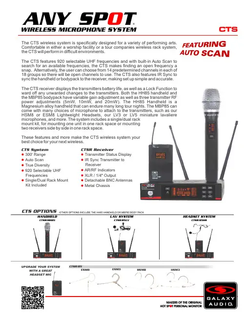
ROD
SHARP EDGE OF
A
RETAINING RING FACES
ROD SEAL
OUTWARD AS SHOWN (NOTE ORIENTATION)
BODY
SECTION A-A
FIGURE 2
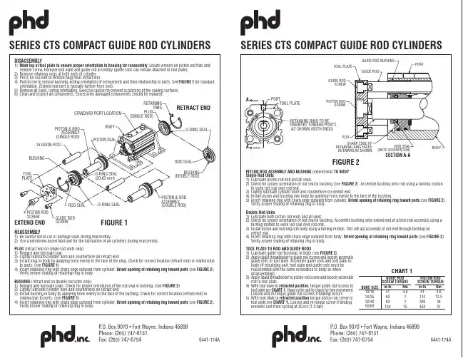
PISTON ROD ASSEMBLY AND BUSHING (extend end) TO BODY Single Rod Units 1) Lubricate piston rod end and all seals. 2) Check for proper orientation of rod seal in bushing (see FIGURE 2). Assemble bushing onto rod using a turning motion
TOOL PLATE
GUIDE ROD SCREW
GUIDE ROD BUSHING GUIDE ROD
PORT
A
PORT
TOOL PLATE
CTS免疫细胞SR产品说明书

Comparable expansion and transduction of CART-19 cells in human AB serum and CTS Immune Cell SR
Cded in CTS OpTmizer supplemented with human serum or CTS Immune Cell SR show similar growth kinetics and total fold expansion after two weeks in culture. Left panel: Growth kinetics from 1 representative donor. Right panel: Fold expansion of total T cells at the end of culture (day 12). Bars represent averages of 4 normal donors.
CTS Immune Cell SR supports T cell lentiviral vector transduction when compared to human sera.
CART-19 cells grown in CTS OpTmizer with CTS Immune Cell SR supplementation showed similar potency and efficacy as control CART-19 grown in CTS OpTmizer with human serum as measured by tumor burden bioluminescence (top) and animal survival (bottom panel).
CTS无线系统产品说明书
CTSThe CTS wireless system is specifically designed for a variety of performing arts. Comfortable in either a worship facility or a tour companies wireless rack system, the CTS will perform in difficult environments.The CTS features 920 selectable UHF frequencies and with built-in Auto Scan to search for an available frequencies, the CTS makes finding an open frequency a snap. Alternatively, the user can choose from 14 predetermined channels in each of 18 groups so there will be open channels to use. The CTS also features IR Sync to sync the handheld or bodypack to the receiver, making set up simple and accurate.The CTS receiver displays the transmitters battery life, as well as a Lock Function to ward off any unwanted changes to the transmitters. Both the HH85 handheld and the MBP85 bodypack have variable gain adjustment as well as three transmitter RF power adjustments (5mW, 10mW, and 20mW). The HH85 Handheld is a Magnesium alloy handheld that can endure many long tour nights. The MBP85 can come with many choices of microphone to attach to the transmitters, such as our HSM8 or ESM8 Lightweight Headsets, our LV3 or LV5 miniature lavaliere microphones, and more. The system includes a single/dual rack mount kit, for mounting one unit in one rack space or mounting two receivers side by side in one rack space.These features and more make the CTS wireless system your best choice for your next wireless.CTSR/85ESM8HSM3HSM8ESM3CTS OPTIONS-OTHER OPTIONS INCLUDE THE HH85 HANDHELD OR MBP85 BODY PACKI RS Y NCCTS System 300Range ●' Auto Scan ● True Diversity● 920 Selectable UHF ● FrequenciesSingle/Dual Rack Mount ● Kit IncludedCTSR ReceiverTransmitter Status Display ● IR Sync Transmitter to ● ReceiverAR/RF Indicators ● XLR / 1/4 Output●" Detachable BNC Antennas ● Metal Chassis●LAV SYSTEMCTSR/85LVHEADSET SYSTEMCTSR/85HSHANDHELDCTSR/HH85WIRELESS MICROPHONE SYSTEM®ANY SP TO UPGRADE YOUR SYSTEMWITH A GREAT HEADSET MICSpecifications subject to change without notice.V20190422601 E. Pawnee Wichita, KS 67211 316. 263.2852 FAX 316.263.0642 Distributed in Canada by Audio Distributors International (ADI ) 1275 Newton, unit 6 Boucherville, QC J4B 5H2 Canada450.449.8177 FAX 450.449.8180CTSSpecifications:CTS SystemAvailable Frequencies: 920Transmitter Output Level: 5 mW, 10 mW, 20 mW Band: UHF FrequencyOperating Range: Under Typical Conditions 300' (92 m), actual range depends on RF signal absorption, reflection, and inference. Audio Frequency Response: (+/-3dB) 60Hz - 16KHzTotal Harmonic Distortion: (+/-30kHz deviation, 1kHz tone): <1%Dynamic Range: >90dB A-weightedOperating Temperature Range: 14°F to 122°F (-10°C to +50°C),battery characteristics may limit this rangeIncluded Accessories: Single/Dual Rack Kit, Antenna Plugs x2,Power Supply, Antennas x2, 1/4" to 1/4" Audio Cable x1, Quick Start Guide Receiver (CTSR)Audio Output Level (+/-30kHz deviation, 1kHz tone): XLRConnector (into 600 Ohm load), 1/4" Connector (into 3k Ohm load)Output Connections: 1 Male XLR Balanced, 1/4" UnbalancedOutput Impedance: XLR connector 200 Ohms, 1/4" connector 1k Ohms XLR Output: Impedance balanced Pin 1: Ground (cable shield)Pin 2: Audio +Pin 3: No Audio -Sensitivity: -102dBm Image Rejection: >90dBCasing: Metal Chassis EIA STANDARD 1/2 UDimensions: 1.7" x 8.3" x 6.3" (45 x 212 x 160mm) (HxWxD)Weight: 31.7 oz (900 g)Power Requirements: 12Vdc at 500 mA,supplied by external power supplyDynamic Cardioid Handheld Transmitter (HH85)Max Audio Input Level: -4.44dBv (-3 gain)Gain Adjust: software control -3dB to +9dB in 3dB steps RF Output: 5 mW, 10 mW, 20 mW Frequency Response: 60Hz - 15kHzDimensions: 9.68" x 2.08" (246 x 53mm)(LxDia.)Weight: 8.8 oz (250 g) (without batteries)Power Requirements: 2 “AA” Batteries, alkaline or rechargeable Battery Life: About 12 hours (alkaline)Body Pack Transmitter (MBP85)Max Audio Input Level: -6dBV (-3 gain)Gain Adjust: -3dB, 0dB, +3dB, +6dB, +9dB RF Output: 5 mW, 10 mW, 20 mW Input Impedance: 470k OhmsDimensions: 2.51" x 3.85" x 0.90" (64 x 98 x 23 mm)(HxWxD)Weight: 3.17 oz (90 g) (without batteries)Power Requirements: 2 “AA” Batteries, alkaline or rechargeable Battery Life: About 12 hours (alkaline)WIRELESS MICROPHONE SYSTEM®ANY SP TO CTSR ReceiverBACK VIEWTOP VIEWMBP85HH85。
CTS-3000说明书
3.2.10.2 定量线………………………………………………………………………21
3.2.10.3 评定线………………………………………………………………………21
3.2.10.4 增益校正…………………………………………………………………22
3.2.11 存储 主菜单……………………………………………………………22
3.2.13 输出 主菜单………………………………………………………………23
3.2.13.1 亮度……………………………………………………………………23
3.2.13.2 报警器……………………………………………………………………23
3.2.13.3 打印机……………………………………………………………………23
3.3.4 屏幕打印/记录键 …………………………………………………………27
3.3.5 回波显示缩放键 ……………………………………………………………27
第4章 检测应用
4.1 仪器的校准方法和步骤……………………………………………………………28 4.1.1 探头参数设置……………………………………………………………………28 4.1.2 工件参数设置……………………………………………………………………29
3.3 其它专用功能键的操作……………………………………………………………26
3.3.1 增益量减少键 / 增益量增加键………………………………………………26
3.3.2 增益步进调节键
…………………………………………………………26
3.3.3 显示冻结键 *…………………………………………………………………27
3.2.11.1 存储号……………………………………………………………………22
Spears EverTUFF CTS CPVC 热水和冷水管道系统说明书
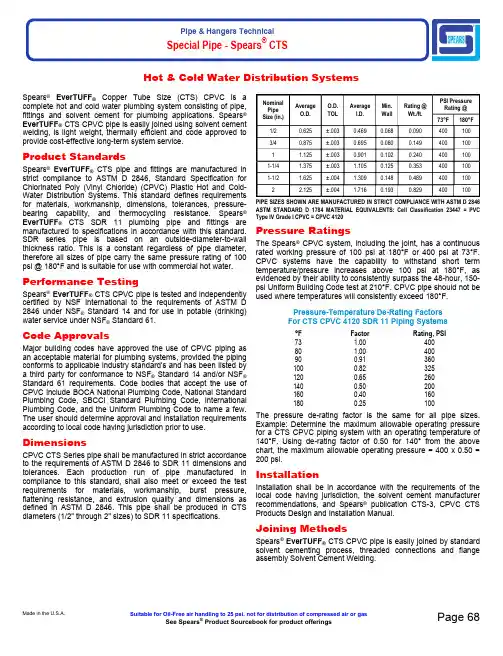
Special Pipe - Spears® CTSSpears®EverTUFF® Copper Tube Size (CTS) CPVC is a complete hot and cold water plumbing system consisting of pipe, fittings and solvent cement for plumbing applications. Spears®EverTUFF® CTS CPVC pipe is easily joined using solvent cement welding, is light weight, thermally efficient and code approved to provide cost-effective long-term system service.Product StandardsSpears®EverTUFF® CTS pipe and fittings are manufactured in strict compliance to ASTM D 2846, Standard Specification for Chlorinated Poly (Vinyl Chloride) (CPVC) Plastic Hot and Cold-Water Distribution Systems. This standard defines requirements for materials, workmanship, dimensions, tolerances, pressure-bearing capability, and thermocycling resistance. Spears®EverTUFF® CTS SDR 11 plumbing pipe and fittings are manufactured to specifications in accordance with this standard. SDR series pipe is based on an outside-diameter-to-wall thickness ratio. This is a constant regardless of pipe diameter, therefore all sizes of pipe carry the same pressure rating of 100 psi @ 180°F and is suitable for use with commercial hot water. Performance TestingSpears®EverTUFF® CTS CPVC pipe is tested and independently certified by NSF International to the requirements of ASTM D 2846 under NSF® Standard 14 and for use in potable (drinking) water service under NSF® Standard 61.Code ApprovalsMajor building codes have approved the use of CPVC piping as an acceptable material for plumbing systems, provided the piping conforms to applicable industry standard's and has been listed by a third party for conformance to NSF® Standard 14 and/or NSF®Standard 61 requirements. Code bodies that accept the use of CPVC include BOCA National Plumbing Code, National Standard Plumbing Code, SBCCI Standard Plumbing Code, International Plumbing Code, and the Uniform Plumbing Code to name a few. The user should determine approval and installation requirements according to local code having jurisdiction prior to use. DimensionsCPVC CTS Series pipe shall be manufactured in strict accordance to the requirements of ASTM D 2846 to SDR 11 dimensions and tolerances. Each production run of pipe manufactured in compliance to this standard, shall also meet or exceed the test requirements for materials, workmanship, burst pressure, flattening resistance, and extrusion quality and dimensions as defined in ASTM D 2846. This pipe shall be produced in CTS diameters (1/2" through 2" sizes) to SDR 11 specifications.NominalPipeSize (in.)AverageO.D.O.D.TOLAverageI.D.Min.WallRating @Wt./ft.PSI PressureRating @73°F180°F 1/20.625±.0030.4690.0680.0904001003/40.875±.0030.6950.0800.1494001001 1.125±.0030.9010.1020.2404001001-1/4 1.375±.003 1.1050.1250.3534001001-1/2 1.625±.004 1.3090.1480.4894001002 2.125±.004 1.7160.1930.829400100 PIPE SIZES SHOWN ARE MANUFACTURED IN STRICT COMPLIANCE WITH ASTM D 2846 ASTM STANDARD D 1784 MATERIAL EQUIVALENTS: Cell Classification 23447 = PVC Type IV Grade I CPVC = CPVC 4120Pressure RatingsThe Spears® CPVC system, including the joint, has a continuous rated working pressure of 100 psi at 180°F or 400 psi at 73°F. CPVC systems have the capability to withstand short term temperature/pressure increases above 100 psi at 180°F, as evidenced by their ability to consistently surpass the 48-hour, 150-psi Uniform Building Code test at 210°F. CPVC pipe should not be used where temperatures will consistently exceed 180°F.Pressure-Temperature De-Rating FactorsFor CTS CPVC 4120 SDR 11 Piping Systems°F Factor Rating, PSI73 1.0040080 1.00400900.913601000.823251200.652601400.502001600.401601800.25100The pressure de-rating factor is the same for all pipe sizes. Example: Determine the maximum allowable operating pressure for a CTS CPVC piping system with an operating temperature of 140°F. Using de-rating factor of 0.50 for 140° from the above chart, the maximum allowable operating pressure = 400 x 0.50 = 200 psi.InstallationInstallation shall be in accordance with the requirements of the local code having jurisdiction, the solvent cement manufacturer recommendations, and Spears® publication CTS-3, CPVC CTS Products Design and Installation Manual.Joining MethodsSpears®EverTUFF® CTS CPVC pipe is easily joined by standard solvent cementing process, threaded connections and flange assembly Solvent Cement Welding.Made in the U.S.A.Suitable for Oil-Free air handling to 25 psi, not for distribution of compressed air or gasSee Spears® Product Sourcebook for product offerings Page 68Hot & Cold Water Distribution SystemsSpecial Pipe - Spears® CTSSolvent Cement WeldingThis is the most common joining method used with CTS CPVC. See Installationsection for industrial pressure pipe for basic solvent cementing guidelines.CTS Solvent Cement SelectionCodes require use of solvent cement conforming ASTM F 493 and designatedspecifically for use with CTS CPVC products in accordance with ASTM D 2846.Spears®EverTUFF® CTS-5 CTS CPVC "One-step" (primerless) cements maybe used without primer if codes permit, or may be used with a primer whererequired by code. - Always CHECK LOCAL CODES.Set and Cure TimesPipe and fitting joint assembly must be allowed to set without any stress on thejoint for one to five minutes depending on the pipe size and temperature.Following the initial set period, the assembly can be handled carefully.FOLLOW THE CEMENT MANUFACTURER'S RECOMMENDED CURE TIMESPRIOR TO PRESSURE TESTING. - FAILURE TO DO SO WILL RESULT INJOINT FAILURE.Minimum Cure Time Prior to Testing at 150 psi with ColdWater (based on use of one-step CPVC cement or two-stepcement systems)Pipe Size (in.)Ambient Temperature During Cure Time>60°F40°F - 60°F<40°F3/8 1 hr 2 hrs 4 hrs1/2 1 hr 2 hrs 4 hrs3/4 1 hr 2 hrs 4 hrs1 1 hr2 hrs 4 hrs1-1/4 2 hrs 4 hrs8 hrs1-1/2 2 hrs 4 hrs8 hrs2 2 hrs 4 hrs8 hrs •NOTE Wait 24 hours prior to putting system into hot water service when installed at cure temperatures above 60°F; wait 48 hours prior to putting system into hot water service when installed at cure temperatures below 40°F Solvent Cement Joining.Wall PenetrationBuilding codes require that a fire-rated wall or floor must be sealed back to its original integrity when penetrated. Several sealants and materials are suitable for use with Spears®EverTUFF® CTS CPVC pipe to construct an appropriate UL Classified fire-rated penetration system. When installed properly, these systems will provide a two-hour fire rating. Consult local building code requirements.•NOTE Caution: Certain fire-stopping sealants and components contain stress cracking agents and other chemicals which may cause damage to CPVC piping; contact the appropriate manufacturer for compatibility with CPVC prior to use.•NOTE When installing CPVC in areas where the system must be drained to protect it from freezing, the lines must be sloped to drain.Underslab InstallationsSpears®EverTUFF® CTS CPVC products are approved for underslab installations (with joints) in all model-plumbing codes. When performing underslab installations, it is important to support the tube evenly on a smooth surface. The bedding and backfill should be sand or clean soil that is free from sharp rocks and other debris that could damage the pipe.Underslab installations that contain joints must be pressure tested before pouring the slab. NOTE: IAPMO IS 2098, "Installation Standard for CPVC Solvent Cemented Hot and Cold Water Distribution Systems," requires a test at 150 psi for 2 hours. The pipe should be sleeved where it penetrates the slab, along with construction joints within the slab. Spears®EverTUFF® CTS pipe is also manufactured in coils for underslab installations to eliminate joints. When turning coiled pipe up through a slab, into walls, etc., make sure the pipe does not kink. Sections of pipe that contain kinks must be cut out and replaced. Freeze Protection/Sunlight ExposureCPVC piping must be protected from freezing in all installation locations. Attention shall be paid to local insulating techniques and codes that require a particular method. Use only methods and materials suitable for use with CPVC piping. Where freezing is not an issue, CPVC shall not be installed so as to be subject to direct sunlight after installation and not installed on the surface of a building, unless protected by a covering or a chemically compatible paint, such as water based Latex.Hose Bibb InstallationHose bibbs are to be connected only to metal system components which are adequately anchored to the building structure. CPVC plastic systems must terminate in the wall.Water Heater ConnectionsBefore attempting to use Spears®EverTUFF® CTS CPVC in water heater connections, determine if local plumbing codes contain detailed requirements for connections to gas or electric storage-type heaters.DO NOT use Spears®EverTUFF® CTS CPVC products with commercial-type, non-storage water heaters.For areas where local plumbing codes do not have requirements, the following information can be used as a guide for water heater connections:• On electric water heaters, CPVC can be joined directly to the heater, using metal-to-CPVC transition fittings.• On high-efficiency gas water heaters that use plastic vent piping, CPVC can be joined directly to the heater in the same way as an electric water-heater connection.• On all other gas water heaters, there should be at least 6" of clearance between the exhaust flue and any CPVC tubing. A minimum of 6" metallic pipe should connect directly to the heater so that the CPVC tubing cannot be damaged by the buildup of excessive, radiant heat from the flue.• A temperature/pressure relief valve should be installed so that the sensing element contacts the water at the top of the heater.Page 69Suitable for Oil-Free air handling to 25 psi, not for distribution of compressed air or gas Spears® Manufacturing CompanySee Spears® Product Sourcebook for product offeringsSpecial Pipe - Spears ®CTS• Spears ®EverTUFF ® CTS CPVC products are approved by all model codes for use as relief-valve drain lines. A metal-to-CPVC transition fitting should be used to connect the tubing to the relief valve, with the tubing continued to the outlet. Both horizontal and vertical pressure relief drain should be supported every 3 feet. For horizontal runs, slope the tubing toward the outlet. Pipe must discharge to the atmosphere at an approved location.• Instantaneous water heaters (i.e., under sink units) require at least 6" of metallic pipe connected to heater inlet and no CVPC installed downstream.TRANSITION JOINTS AND FITTINGSSpears ®EverTUFF ® CTS CPVC pipe can be connected to copper, brass, valves, and other materials using a variety of transition fittings including unions, compression fittings, specially reinforced male and female adapters, flanged joints, grooved joints and other readily available transition fittings.Do not thread CPVC pipe and do not use regular CPVC female threaded fittings. Regular CPVC male threaded fittings shall only be used on cold waterapplications. Special reinforced male adapters, female adapters and otherfittings with brass threads are recommended for hot water applications andthreaded transitions to metal pipe. All approved threaded CPVC joints must beaccessible. (See also Water Heater Connections section for additional installation details).Standard compression fittings with brass ferrules can be used; however, PTFE tape must be applied over the brass ferrule to compensate for the dissimilarthermal expansion rates between the brass and CPVC. Caution must beexercised to prevent over tightening of compression fittings. Use extreme care when soldering any metal system to prevent flame contact with or heat distortion in CPVC pipe and fittings.Assembling Threaded Connections Threaded connections require the application of a thread sealant that is compatible with CPVC material. Spears ® recommends the use of Spears ®BLUE 75™ Thread Sealant. Apply sealant to the male threads only. Make sure all threads are covered. DO NOT clog the waterway with excess sealant. If PTFE tape is used, Spears ® recommends a thickness of at least .0035" that meets or exceeds military specification, MIL-T-27730A. DO NOT use a combination of tape and thread sealant on the same joint. Apply PTFE tape in the direction of the threads by starting with the first full thread and continuing over the entire thread length. Make sure all threads are covered. Generally, 2 - 3 wraps are sufficient to produce a watertight connection.DO NOT over-torque any threaded connections. Generally, one to two turns beyond finger-tight are required for a threaded connection. Factory testing hasindicated that 10 - 25 ft-lbs of torque is adequate to obtain a leak-free seal.Spears ® recommends the use of a strap wrench when installing threadedconnections.Hanger/Support SpacingSpears ®EverTUFF ® CTS CPVC pipe is rigid, it requires fewer supports than flexible, plastic systems. Vertical runs should be supported at each level so that the weight of the run is not placed on a fitting or a joint. Horizontal runs require support every 3 feet for 1/2" - 1" diameter pipe and every 4 feet for 1-1/4" and larger diameters. Support spacing should be in accordance with applicable local codes. Horizontal runs must be braced so that the stress loads (caused by bending or snaking) will not be placed on a fitting or a joint. Hanger support spacing information is shown in Table A.Spears ® recommends that hangers, designed for supporting CPVC, be used tosupport CPVC piping. However, some hangers, designed for steel pipe, may be used if their suitability is clearly established. These hangers must be selected toaccommodate the specific pipe size. In addition, they cannot contain rough orsharp edges that contact the pipe, and they must not bind the pipe from axial movement that is caused by expansion and contraction.Pipe Size (in.)Maximum Hanger Support Spacing 3/8 3 ft 1/2 3 ft 3/4 3 ft13 ft 1-1/4 4 ft 1-1/2 4 ft 24 ft Thermal Expansion All piping systems expand and contract with changes in temperature. This issue must be addressed with appropriate system design to prevent damage to thesystem. Spears ®EverTUFF ® CTS CPVC pipe will expand or contract approximately 3.8 inches per 100 feet of pipe with every 100°F of temperaturerise or fall. The effects of expansion/contraction are usually absorbed by the system at changes of direction in the piping. In other words, long, straight runs of piping are more susceptible to experiencing measurable movement with changes in temperature. As with other piping materials, the installation of an expansion loop or offset is required on long, straight runs which will allow the piping system to absorb the forces generated by expansion/contraction without damage. The rate of expansion does not vary with pipe size. The effects of expansion/contraction are more pronounced on hot water lines. See Thermal Expansion & Contraction section under Engineering and Design Data for Industrial Piping in this manual for information on calculating movement andexpansion loops.System TestingOnce the system has been installed and allowed to cure properly, the systemshall be tested in accordance with applicable code requirements. When testingwith water (hydrostatic testing), the system must be slowly filled with water andthe air bled from the highest and furthest points in the system before test pressure is applied. Air must be removed from piping systems to prevent it from being locked in the system when pressure is applied. Failure to do so could beharmful to job site personnel should a failure occur. If a leak is found, the affected product must be cut out and discarded. A new section can be installedusing couplings or other approved means.Made in the U.S.A.Suitable for Oil-Free air handling to 25 psi, not for distribution of compressed air or gasSee Spears ® Product Sourcebook for product offeringsPage 70。
HDMI CTS Sink Test Library 使用手册说明书

P A D -T -M :3574.3259.02/01.00/C I /1/E NHDMI CTS Sink Test Library ManualM a n u a lB r o a d c a s t a n d M e d i a2115.7916.02–03The manual describes the content of the HDMI CTS sink test library(2115.7900.00).The library is part of: R&S®VT-B23622115.7700.06R&S®VT-B23632115.7716.06©2016Rohde&Schwarz GmbH&Co.KGMuehldorfstr.15,81671Munich,GermanyPhone:+49894129-0Fax:+4989412912164E-mail:**********************Internet:Subject to change–Data without tolerance limits is not binding.R&S®is a registered trademark of Rohde&Schwarz GmbH&Co.KG.Trade names are trademarks of the owners.The following abbreviations are used throughout this manual:R&S®XYZ123is abbreviated as R&S XYZ123HDMI CTS Sink Test Library ContentsContents1Getting Started (4)1.1Contents of the Disk (4)1.2Version History (4)1.3System Requirements (4)1.4Installation Instructions (5)2Using the Library (5)HDMI CTS Sink Test Library Getting Started1Getting StartedThis disk contains HDMI signal files that are used in the HDMI generator application ofthe instrument.1.1Contents of the Disk● This document● Install.bat● HDMI.exe● 7z archive files1.2Version HistoryFor information on the current firmware version refer to the release notes of theinstrument.1.2.1Version1.20Updated HDR test pattern with new video content.Updated3D test pattern with3D picture content.1.2.2Version1.10New HDR test pattern.Updated test pattern for21:9testing:circle element added to determine the correctaspect ratio.1.2.3Version1.00Initial release.1.3System RequirementsThe Rohde&Schwarz Web Configurator shows you the required hardware andsoftware options.It is provided in the Internet:On the Rohde&Schwarz Home Page(),go to the instrument-specific site and configure yourproduct.If you need any further information,refer to the help of the Rohde&SchwarzWeb Configurator.HDMI CTS Sink Test Library Using the Library1.4Installation InstructionsTo install the HDMI CTS sink test library on the instrument,the following procedure isrecommended:1.Copy the complete content of the disk to a USB flash memory.2.Connect the USB flash memory to the instrument.3.Open the file explorer and navigate to the folder on the USB flash memory thatcontains the copied disk content.4.Execute the Install.bat file and wait for the installation routine to complete thesetup.2Using the LibraryThe content of the library is integrated in the CTS test cases of the HDMI generatorapplication.For further details refer to the user manual of the instrument.。
cts i28说明书
cts i28说明书
1、按菜单,进入主菜单键,选择“程序设置”。
2、再点击“程序设计”,按照菜单,设置相应参数即可。
3、选择测试类型:如果判断标准以压降为单位,“压力衰减-p”这种模式;如果判断标准以另一个为单位,选“压力衰减-泄漏标准”这种模式。
4、设置测试时间:把测试产品相应的时间输入即可。
5、设置测试压力类型:输入“测试产品的压力即可”,最大、最小压力比目标压力大或小相对应设置。
6、设置产品的标准:产品漏多少的参数在此设置,主要设置压损高限,举例:标准是50pa,就压损高限50pa,压损低限-50pa。
CTS 1010S钢轨焊缝超声探伤仪 使用说明书
CTS 1010S钢轨焊缝超声探伤仪使用说明书cts-1010s钢轨焊缝超声探伤仪-使用说明书Cts-1010s钢轨焊接超声探伤仪亲爱的用户:您们好!非常感谢您购买广东汕头超声波电子有限公司超声波仪器分公司的产品,这使我们有机会为您提供服务。
我们将尽最大努力满足您的要求,让您享受超声波仪器分公司产品的卓越性能和质量。
在使用产品之前,请务必仔细阅读本说明书,以便能够正确地进行操作,让您使得顺手,用得顺心。
同时通过手册中的联系方式,可以享受到我们随时准备为您提供的服务。
通过附录,您还可以了解到更多的关于仪器使用方面的知识,有利于更恰当地使用本产品。
我们希望这本“用户手册”能成为我们产品使用过程中的好帮手。
再次感谢您使用我们的产品,希望有更多的机会为您服务!目录1一般安全概述42仪表简介52.1功能和特点52.2主要性能参数62.3仪表板和主要部件说明72.4关键说明82.4.1关键符号和相应含义82.4.2通用旋钮功能92.5仪表菜单流程和说明92.5.1显示屏显示区划分92.5.2菜单列表和说明102.5.3全屏参数的使用143仪器的基本调整和应用163.1仪器的启动、关闭和充电163.1.1启动-关闭。
163.2 163.1.3充电163.2仪器校准173.3如何检测183.4检测过程中一些辅助功能的使用193.4.1自动增益193.4.2波形扩展193.4.3峰值搜索193.4.4报警彩色显示功能13.4.5打开和退出DAC曲线功能203.4.6打开和退出包络功能203.4.7波形比较213.5数据存储和调用213.5.1存储缺陷波形213.5.2使用通道224使用仪器的高级功能224.1连续存储(视频记录功能)224.1.1基本记录和回放224.1.2标记和更改检测位置记录期间234.1.3灵敏度和门调整记录期间234.2测试报告244.3dac曲线制作和删除244.3.1 DAC曲线制作254.3.2dac曲线校正264.3.3单探头DAC曲线报警和存储264.4汉字输入264.4.1拼音输入法274.4.2其他输入274.5数据处理274.6自动校准仪性能284.7校准探头频率295仪器维护和维修295.1锂电池维护295.2仪器维护和维修23025.2.1仪器维护295.2.2仪器维护296服务和技术支持30附录a方波应用31附录B 软件升级方法32附录C连续数据记录操作指南33附录D回放管理软件指南36附录E焊缝GPS位置信息建立指南383。
CTS-22超声波探伤仪使用说明书
CTS-22A/B 超声探伤仪使用说明书1. 概述CTS-22A/B型超声探伤仪系携带式A型脉冲反射式超声探伤仪器,可用交流或电池供电工作。
本仪器采用高性能器件,SMT(即贴片技术)安装和高亮度内刻度示波管,具有工作频率范围宽、探伤灵敏度高、稳定性好、故障率低、显示波形清晰和小型、省电、方便等特点。
仪器可用于金属和部分非金属材料的超声无损检测,尤其适用于流动性大的野外或高架空探伤作业。
2. 主要技术性能2.1工作频率范围接收放大器频带宽度0.5~10MHz。
2.2工作方式单探头发射接收或双探头分别发射接收。
2.3衰减器衰减器总衰减量80dB(20dB×2、2dB×20);<增益>电位器连续调节量0~6dB;衰减器衰减误差:每2dB不大于±0.1dB。
2.4放大线性2~5MHz 1级(JIS Z 2344)。
2.5 抑制电平<抑制>电位器调节范围:垂直刻度的0~80%。
2.6 发射脉冲幅度阻尼电阻50Ω时,约500Vp 。
2.7 发射脉冲重复频率分500、250、125、62.5Hz 四档,与<探测范围>粗调开关同轴调节。
2.8 探测范围10~5000mm(钢纵波);<探测范围>粗调开关分10、50、250mm 及1m(钢纵波)四档,微调由多圈电位器控制。
2.9 时间轴线性不大于1%(JIS Z 2344)。
2.10 脉冲移位距离不小于400mm(钢纵波),由多圈电位器控制。
2.11 配用探头可配用汕头超声仪器研究所生产的普通和窄脉冲系列探头中标称频率为0.5~10MHz 的各种探头。
2.12 探伤灵敏度余量配用2.5Z20N 直探头,JIS-STB-G V15-2试块平底孔反射波高为垂直刻度50%时的灵敏度余量为46dB 以上。
2.13 远距离分辨力2MHz 以上A 级(JIS Z 2344)。
2.14 适用电源AC :220V %,50~60Hz(电源电压可按用户要求改为100V 或1020+-110V);DC :12.5±2V(镍氢电池1.25V×10)。
汕头超声波仪器CTS 4020使用说明书.
电池类型锂电池(7.2V、7.2Ah
工作时间h使用7.2Ah锂电池
≥6 (与背景光亮度有关
工作电压V 6 ~ 9 DC (外部电源,6.0 ~ 8.4 (电池。工作温度℃–10 ~ 50
重量kg约1.94(不含电池
尺寸mm260 ×180 ×95 (宽×高×深
注:不同型号仪器在功能或指标上的差别,见表1。
闸门:控制a、b闸门所必需的功能,以及跟踪闸门设定。
DAC :制作DAC曲线、TCG曲线,以及用DAC、TCG曲线对缺陷回波进行评价的各项功能。
存储:用于存入、调出和删除数据集,以及数据集的其他管理。
预置:配置仪器的其它设定,包括时钟、打印、显示颜色等。
根据需要进行相应的选择,当某一个主菜单被选择时,屏幕右方将显示与该主菜单相关的子菜单内容,详见3.1菜单目录。
DAC+6.0dB
DAC修正
off
a闸门起位*
35.0mm
定量线
DAC+0.0dB
增益校正
0.0dB DAC帮助
评定线
DAC-6.0dB
曲线选择
评定线
∨ ∨
存储存储号
1
∧ ∧
调出ห้องสมุดไป่ตู้
off
测试信息
off
删除所有
off
存入
off
预览
off
转存U盘
off
删除
off
off
转存选项
当前
∨ ∨
预置区域
3区
∧ ∧ ∧
工作频率
1~4MHz
增益微调
双探头
off
检波方式
双向
自动增益
off
- 1、下载文档前请自行甄别文档内容的完整性,平台不提供额外的编辑、内容补充、找答案等附加服务。
- 2、"仅部分预览"的文档,不可在线预览部分如存在完整性等问题,可反馈申请退款(可完整预览的文档不适用该条件!)。
- 3、如文档侵犯您的权益,请联系客服反馈,我们会尽快为您处理(人工客服工作时间:9:00-18:30)。
目 录1. 功能简介 (1)2. 硬件认识与配置 (1)2.1 电池仓 (1)2.2 CTS电池接口介绍 (2)2.3 电池正负极及SC、SD引脚的判断 (3)2.4 电池与CTS的连接 (3)2.5 CTS箱号及GGS-ID (4)2.6通讯口介绍 (5)3. 联机设置 (6)3.1 COM口的设置 (6)4. CTS与GGS指示信号的识别 (7)4.2 信号识别 (7)5. 软件介绍与基本操作 (8)5.1 各快捷功能介绍 (8)5.2 工作模式及各参数、条件介绍 (8)5.2.1 静置 ST (8)5.2.2 恒流充电 (8)5.2.3 恒压充电 (9)5.2.4 恒流放电DC (9)5.2.5 恒功率放电CP: (9)5.2.6 COMMAND (9)5.2.7 跳转(GOTO) (9)5.2.8 停止 (9)5.3 正常判断条件(To Next Step) (10)5.3.1 结束时间 (10)5.3.2 结束电压 (10)5.3.3 结束电流 (10)5.3.4 结束容量 (10)5.3.5 RSOC (10)5.3.6 -△V: (10)5.4 例外限制条件(Stop) (11)5.4.1 电流台阶 (11)5.4.2 最小容量 (11)5.4.3 最大容量 (12)5.4.4 △DCR (12)5.5 安全保护 (12)5.5.1 电压设置 (12)5.5.2 电流范围± (12)5.6 数据记录条件 (13)5.7 启动电池进行充放电 (13)5.7.1 修改CTS箱号及GGS—ID (13)5.7.2 联机 (13)5.7.3启动电池 (14)5.8 制程(tpl)文件的保存 (16)5.9 更改通道工作模式 (18)5.10 启动后通道的版面信息 (18)6. 数据查看及图形分析 (19)6.1 图形数据的打开 (19)6.2 图形数据的查看技巧 (20)6.2.1 数据折叠 (20)6.2.2 时间单位设置 (20)6.2.4 查看测试日志 (22)6.2.5 数据另存为 (22)6.2.6 生成EXCEL文件格式文件 (23)6.2.7 图形查看与设置 (23)6.2.8 输出图形文件 (24)6.2.9 图形分析 (24)7. GGS的认识与使用 (26)7.1 联机 (26)7.2 读取电池的Gas Gauge数据 (27)7.3 电池信息比对 (27)CTS 使用说明书1. 功能简介主要应用于电池包生产中的寿命老化测试(Circle Life Testing),和智能电池数据训练(Circle Learning)以及质量控制。
2. 硬件认识与配置本公司生产的充放电机台硬件部分为模块化设计,每8个独立信道为一个模块。
一般每台机柜由40个独立通道构成,实物如图2-1所示。
图2-1 电池测试系统 CTS2.1 电池仓由图可知,每台机柜由5台相互独立工作的CTS和对应的电池仓组成。
电池仓的构成如图2-2所示。
图2-2 电池仓构成我们的电池仓由2mm厚的钢板组成,在整个系统中既起到了方便测试又具有保证测试安全的双重功效。
与此同时我们在电池仓内铺设有由阻燃抗静电PVC 材料制作的塑料托盘如图2-3所示。
塑料托盘上还铺设了一层由硅胶制成的天然无污染的防滑垫如图2-4所示,它能很好的保证我们的电池在电池仓在开关的过程中,不至与连接器脱落。
图2-3 黑色阻燃抗静电塑料托盘 图2-4 硅胶防滑垫2.2 CTS电池接口介绍与智能电池连接的接口如图2-5所示。
各管脚从左至右分别为:V+、I+、I+、C、D、I-、I-、V-。
在实际使用当中我们需要将V+、I+,I-、V-分别短接起来并对应连接到到电池的正和负。
C、D分别代表SMbus的SMC和SMD。
在与电池连接时对应连接到电池的SC、SD端。
图2-5 设备接口定义2.3 电池正负极及SC、SD引脚的判断首先我们可以通过万用表很方便的测试出电池的正负极,然后将数字万用表调到二极管档,将红表笔接到电池的负极并用黑表笔去接电池的其它引脚(一般电池的引脚个数都会大于4个)当万用表有零点几伏的管压降时即为电池的SC 和SD引脚。
根据智能电池制作时默认将SC引脚靠近电池正极,而将SD引脚靠近电源负极。
这样我们就可以通过这个默认制作规定将SC和SD引脚区分开来。
2.4 电池与CTS的连接在介绍CTS电池接口的时候,我们提到将电池接到CTS设备时需要将CTS 端口的V+、I+,I-、V-分别短接起来。
而我们的设备为了在出厂前更好的对其进行调试我们没有将其短接。
为了解决这个问题,我们需要在外部将它们短接起来。
此处我们采用在连接电池和CTS的导线上将其短接起来的办法。
我们将用于连接电池与CTS得导线制作成如图2-6所示。
图2-6特制连接电池的导线 图2-7 通用连接器在将电池与导线相连接时,需要使用由瑞能公司提供的如图2-7所示的专用连接器。
该连接器具有很强的通用性。
连接器与电池的连接如图2-8所示。
在将电池与连接器相连时,一定要注意将电池的正极负、极连SC、SD四个引脚依次与CTS设备对接起来。
这对保证充放电及智能电池与设备的正常通讯起着至关重要的作用。
我们的设备提供电池反接保护和反接提醒功能。
当电池接反时,设备的通道LED将出现闪烁。
如图2-9所示为电池与CTS设备完整连接图。
图2-8 连接器与电池的连接图图2-9 电池与设备的连接2.5 CTS箱号及GGS-ID在我们的设备中,不同的CTS机台及GGS都有各不相同的箱号。
不同的箱号在多台设备通信中起着十分重要的作用。
如图2-8所示即为显示CTS箱号及GGS-ID的数码管。
图2-8 CTS箱号及GGS-ID2.6通讯口介绍我们的设备采用R/S 232模式,通讯线路在机台的背面,如图2-9所示。
如图我们可以看到我们的设备含有两个串行通讯口——CTS通讯口和GGS通讯口(不含GGS的设备没有GGS通信口)。
图2-9 设备通讯口值得注意的是我们的设备如果是单台的它就不带CM功能,若多台连接使用则必须使用带CM功能的通讯口。
实际使用中,不带CM功能的设备可以直接与计算机相连。
而带CM功能的设备不能直接与计算机相连否则会损坏计算机的串口。
它们之间的连接需要由瑞能公司提供的如图2-10所示的隔离盒实现。
通过隔离盒连接到计算机上还能够系统通信的抗干扰能力。
整个通信连接线路如图2-11所示。
图2-10 隔离盒图2-11 通信线路连接图3. 联机设置对于我们公司生产的CTS设备,每台计算机能够有效控制480个测试通道,增配多串口卡,可以实现多进程控制。
多串口多个程序进程控制时,必须注意以下事项:a.需要更改每个软件的名称,以免注册表重迭。
b.同一台计算机控制的CTS不能有相同的箱号box ID,以免停电恢复时造成数据出错。
3.1 COM口的设置初次使用软件时需要对软件通讯COM端口进行设置。
对COM口的更改受管理权限的控制。
如图3-1我们首先打开我们的CTS软件,选择“管理”菜单下的“管理登陆”命令,进入如图3-2所示“Login”对话框。
输入密码后即可完成管理登陆。
管理密码默认为admin,用户可以根据需要作出相应的修改。
图3-1 选择管理登陆命令图3-2 Login 对话框管理登陆后,我们选择CTS软件“选项”菜单下的“优化自动联机”命令,打开如图3-3所示“优化自动联机”对话框。
在箱号命令栏中,“从”下拉菜单中选择从001,“到”下拉菜单中选择我们计算机连接的设备的最大箱号。
在串行口命令栏中,“从”下拉菜单中选择从COM1,“到”下拉菜单中选择我们计算机连接设备时的最大串口号。
实际使用中我们可以将范围设置得比我们的使用范围略大一些。
图3-3优化自动联机对话框4. CTS与GGS指示信号的识别4.1 CTS信号的识别上电后,CTS设备有一个自检的过程,接口处的LED将从通道1至通道8依 次点亮,最后全部熄灭。
在智能电池进行充放电的过程中,如若发现接口处的LED出现闪烁的情况,则说明电池在充放电的过程中出现了异常。
出现异常的原因以及清除闪烁的方法将在后面的内容进行讲解。
4.2 信号识别当智能电池正确接入CTS设备时,如图4-1所示通道指示灯亮。
它表示智能电池与设备间能够正常通信。
图4-1 通信正常指示灯5. 软件介绍与基本操作5.1 各快捷功能介绍打开软件后,我们可以看见在左侧有一个快捷功能工具栏,如图5-1所示。
图5-1 快捷功能工具栏从左至右它们的含义分别是:1.打开当前数据文件夹,可查询当前测试数据。
2.编辑测试制程,用于编辑充放电的流程及参数的设定。
3.查看窗口,显示每个通道当前工作状态。
4.Flash LED:用于准确定位查询通道。
5.Clear LED:清除所有通道报警闪烁中的LED。
6.查询软件连接状况。
7.更改数据存放路径。
5.2 工作模式及各参数、条件介绍在本设备下,智能电池进行老化和智能数据学习时,可以有多种工作模式。
现将各工作模式及其参数1、参数2的设置介绍如下:5.2.1 静置ST电流回路处于切断状态,但不停地电压信息的采集。
主要要设置的参数为静置时间(结束时间)。
5.2.2 恒流充电参数1设置恒流充电电流大小,一般为电池设计容量的一半。
参数2设置为恒压充电电压大小,一般设置为电池的满充电压。
例如3串锂电池设置为12.6V,4串设置为16.8V。
注:我们的设备在进行充电的过程中分为CC(恒流)和CV(恒压)两个过程。
在充电伊始保持充电电流为参数1设定的恒定值,当电池电压达到参数2设置的电压值时,保持电压值不变而电流值不断地减小,形成一个涓流充电的过程。
整个过程中CC占据大约70%的时间,CV的过程大约为30%的时间。
5.2.3 恒压充电参数1与参数2的设定与恒流充电的一致。
在我们的软件当中,恒压与恒流充电执行的过程完全相同,用户只用选择其中的一种即可。
5.2.4 恒流放电DC恒流放电时,我们只需要且只能设置参数1。
我们设置参数1为用户需要的放电电流大小,一般为电池设计容量的一半。
5.2.5 恒功率放电CP:恒定功率放电模式。
采用硬件乘法器的恒功率算法。
参数1设置为放电功率。
5.2.6 COMMAND命令加载模式,用于智能电池充放电前或充放电结束后为电池加载命令或写入数据。
5.2.7 跳转(GOTO)设置参数1为要跳转到制程的第几步。
结束时间设置跳转的次数。
跳转的设置一般用在对智能电池反复充放电进行老化学习的制程中。
5.2.8 停止通道彻底进入停止状态,智能电池的回路从充放电机完全断开。
此工作模式下用户不需要设置任何参数。
5.3 正常判断条件(To Next Step)5.3.1 结束时间限制对电池的充放电时间。
5.3.2 结束电压限制充放电结束电压(实际使用中我们一般用来设置放电结束电压)。