感应电热水龙头说明书英文版范例
英文说明书范文
英文说明书范文Thank you for purchasing our product. Please read the following instructions carefully to ensure proper use and maintenance.1. Installation- Carefully unpack the product and remove any packaging materials.- Place the product on a stable and level surface.- Connect the power supply according to the provided instructions.2. Operation- Use the power button to turn on the product and adjust settings as needed.- Follow the user manual for specific operation instructions.- Do not operate the product with wet hands or in wet conditions.3. Maintenance- Regularly clean the product with a soft, dry cloth.- Avoid using harsh chemicals or abrasives when cleaning.- Keep the product away from direct sunlight and extreme temperatures.4. Troubleshooting- Refer to the troubleshooting section of the user manual for common issues and solutions.- Do not attempt to repair the product yourself. Contacta qualified technician for assistance.5. Safety Precautions- Always follow the manufacturer's guidelines for safe use of the product.- Keep the product away from children and pets.- Unplug the product during periods of non-use or before performing any maintenance.6. Warranty- This product is covered by a limited warranty. Please refer to the warranty card for details on coverage and claims procedures.We hope you enjoy using our product. If you have any questions or concerns, please contact our customer service team for assistance. Thank you for choosing our product.。
说明书(英文版)

说明书(英文版)Product ManualIntroduction:This product manual provides detailed instructions and guidelines for effective usage of the product. It aims to help users understand the features, functions, and proper handling of the product. Please read the manual carefully before using the product to ensure optimal performance and to prevent any potential risks.1. Product Overview:1.1 Description:The product is a high-quality electronic device designed to simplify daily tasks. It offers a wide range of features, including but not limited to [list key features]. With its user-friendly interface and intuitive controls, it enhances user experience and productivity.1.2 Package Contents:- [List all included items]- [Provide detailed description for each item]2. Safety Instructions:2.1 General Safety Precautions:- Before using the product, carefully read all safety instructions provided in this manual.- Keep the product away from water, fire, and extreme temperatures.- Do not disassemble or attempt to repair the product yourself.2.2 Electrical Safety:- Only use the provided power cord and adapter. Do not use damaged cords or adapters.- Plug the power cord into a grounded outlet to prevent electrical shock.- Unplug the product during thunderstorms or if it will not be used for an extended period.2.3 User Safety:- Follow the recommended weight and size limits when operating or carrying the product.- Do not expose the product to excessive force or impact.3. Product Setup and Configuration:3.1 Installation:- Choose a suitable location for the product, free from obstacles or potential hazards.- Connect the necessary cables as indicated in the manual.- Power on the device and follow the on-screen setup instructions.3.2 Initial Configuration:- Customize the product settings as per your preference.- Calibrate the device if necessary.- Set up user accounts and passwords, if applicable.4. Operating Instructions:4.1 Basic Functions:- Familiarize yourself with the product's basic functions, such as power on/off, volume control, and screen navigation.- Learn how to switch between different modes or applications.4.2 Advanced Features:- Explore the advanced features of the product, such as [list key advanced features].- Follow the provided instructions to utilize these features effectively.5. Maintenance and Care:5.1 Cleaning:- Before cleaning the product, ensure it is turned off and unplugged.- Use a soft, lint-free cloth to gently wipe the product's surface.- Do not use liquid cleaners or abrasive materials that may damage the device.5.2 Battery:- Follow the recommended charging procedures and use only compatible chargers.- Avoid exposing the battery to extreme temperatures.- Dispose of the battery responsibly according to local regulations.6. Troubleshooting:If you encounter any issues while using the product, consult the troubleshooting section of this manual. It provides solutions to common problems and answers to frequently asked questions. If the issue persists, contact our customer support for further assistance.7. Warranty and Support:The product comes with a limited warranty against manufacturing defects. Refer to the warranty card or our website for detailed warranty terms and conditions. For any inquiries or product support, please reach out to our customer service team via the provided contact information.Conclusion:This manual serves as a comprehensive guide for users of the product. By following the instructions and guidelines provided, users can optimize their experience and ensure the safe and effective usage of the product. For any updates or additional information, please visit our website.Note: This is a sample product manual, and the content provided is fictional. Please refer to the actual product manual for accurate instructions and guidelines.。
AQUAMAX FULL PRO FLEX X JET 9.5KW AQUAMAX TOP SMAR

These instructions contain all the necessary fitting and operating instructions for your electric shower.Care taken during the installation will provide a long, trouble free life from your shower.INSTRUCTION GUIDE AND USER MANUALINSTANTANEOUS ELECTRIC WATER HEATER - MANUALAQUAMAX FULL PRO FLEXX JET 9.5KWAQUAMAX TOP SMART 9.5 KWAQUAMAX FULL PRO FLEX SMART 9.5KWAQUAMAX PRO X JET 9.5 KWByAQUABELLA SHOWER CO.,LTD.PLEASE READ THIS IMPORTANT SAFETY INFORMATIONIMPORTANTGENERAL ADVICE TO SHOWER UNIT USERSGENERAL LAYOUT OF A SHOWER INSTALLATIONRECOMMENDED INSTALLATION DIMENSIONS FOR ALL MODELS AQUAMAX FULL PRO FLEX , AQUAMAX TOP AND AQUAMAX PRONo. 1A 1B 2 3 3A 3B 4 5 6 7 8 9A 9B 10A 10B 10C 10D 10E 10F 11 12 13 14 15 16 17 18 19AQUAS CODEAS02001CPAS02086CPAS06003AS07018CPAS07008CPAS07009CPAS10001CPAS05012CP6AS05015CPAS09002CPAS06040CPAS03076CPAS03146CPAS50001WHAS50001GBAS50001FCAS50002WHAS50002GBAS50002FCAS50003AS50004AS50005AS50006AS50007AS50008AS50009AS50010AS50011 DESCRIPTIONOVERHEAD - SMART 200 - NO AIR CHROMEOVERHEAD X JET 200 CHROME2.5mm SEALING WASHER FOR SHOWER HOSE - PACK 5TOP CONNECTER FOR SHOWER ARMNON ROTATION SHOWER ARM AND HEATER CONNECTOR FOR AQ5517 / AQ5611NON ROTATION SHOWER ARM AND HEATER CONNECTOR FOR AQ5518 / AQ5612FREE FIX WALL BRACKET SET CW FIXINGSWALL BRACKET PACK FOR SLIDE BAR X 2 ( FREE FIX ) CHROMESHOWER TUBE 600 X 25MM WITH END CAPS CHROMEFRONT LOADING SLIDER MECHANISM CHROMESMOOTH 1.5M PVC SHINY HOSE WITH ABS CONICAL NUTS CHROMEHAND SHOWER BELLA 3F - NO AIR CHROMEHAND SHOWER X JET 1F CHROMEHEATER COVER COMPLETE 1 HANDLE WHITEHEATER COVER COMPLETE 1 HANDLE GLOSS BLACKHEATER COVER COMPLETE 1 HANDLE FULL CHROMEHEATER COVER COMPLETE 1 HANDLE WHITEHEATER COVER COMPLETE 1 HANDLE GLOSS BLACKHEATER COVER COMPLETE 1 HANDLE FULL CHROMESCREW FIXATION PACK FOR HEATERTHERMAL CUT OFF DEVICEDIVERTOR VALVE ASSEMBLY FOR AQ5517 AND AQ5518ELECTRICAL TERMINAL BLOCKPOWER SWITCH ASSEMBLYGRILLON HEATER TANK ASSEMBLYVOLUME CONTROL VALVE ASSEMBLY COMPLETEPRESSURE RELIEF VALVE TUBEFILTERSPARE PART DETAILS FOR AQUAMAX WATER HEATERSAQUAMAX FULL PRO FLEX 9.5 KW MANUAL WATER HEATERS1B3B23A111A4429A1112111618171010141315555114444228666755555239B1010111A443A211121116181714151144442231B3B2119A1112111618171010141315555112286667555559BAQUAMAX FULL PRO FLEX AND AQUAMAX TOPASSEMBLY OF UPPER SHOWERING COMPONENTSASSEMBLY OF UPPER SHOWERING COMPONENTS AQUAMAX FULL PRO FLEX AND AQUAMAX PROELECTRICAL CONNECTIONSELECTRICAL WIRINGFITTING THE BACK COVER INTO POSITIONDIVERTOR HANDLE ( UPPER HANDLE )VOLUME CONTROL HANDLE ( LOWER HANDLE )Make sure that the Divertor spindle and the raised button on the divertor handle are in the 12 O'clock position before fitting the cover.Turn the stabilizer valve spindle and volume handle fully clockwise until resistance is felt.F it cover into position and re-fit cover fixation screws.S tabilizer valveWhen fitting the cover, it is important to align the divertor spindle andvolume control spindle inside the heater.COMMISSIONING THE SHOWER HEATER2. Turn on the waterand electricity,Push the on/off button,if there is any leakageinside the heater or1. Before installation,handle clockwise untilresistance is felt.Connect the waterand electricity supply.IMPORTANT NOTE FOR THE INSTALLERWARNING ....failure to remove that part after commissioningwill result in NO hot water reaching the shower.OPERATING THE SHOWER1.Switch on electrical supply - pull cord or wall mounted switch.2.Press the ON / Off Button to start the flow of water.3.Turn the divertor handleto select the showeringfunction you requireLeft for Hand-shower& Right for Overhead.4.When turning the VolumeControl Handle, this willchange the outputtemperature of the water.5.In the winter months,the heater should be operatedat full power ( 9.5 KW )to ensure an adequate amountof hot waterIn the summer months,the ECO button can be activatedwhich will reduce the KW outputdown to 5.0 KW.6.T o turn off the shower unit,press the ON / OFF button.IMPORTANT NOTESThe Higher the flow the temperature will decrease.The Lower the flow the temperature will increase.It is recommended that you start the shower with the volume handle in the fullyanti clockwise / cold position as this will provide maximum flowIf a higher outlet temperature is required, Rotate the volume handle in a clockwise direction.HAND-SHOWER ON / OFF BUTTONMAINTENANCE – CLEANING THE FILTERSTEP 1Remove front cover assembly, loosen these two screws, the decor cover can be removed.STEP 2Use flat-head screw driver to remove filter, clean it, and refit.STEP 3Clean the filter and refit.FIL TER2. If scale deposits are stubborn,Soak the shower-head or hand-showerin a proprietary Limescale remover andrinse thoroughly before use.Your AQUAS Branded heaters are supplied by Aquabella Shower Co.,Ltd. in Thailand.For information or service assistance , please contact the installer or the localUK distributor from where the heater was purchased.Ai00511. To break away scale deposite on a dailybasis simply rub your thumb over the surfacewhilst the shower is running.SHOWERHEAD CLEANING INSTRUCTIONS。
sloan 奥普帝玛 系列 ON-Q 感应水龙头 说明书
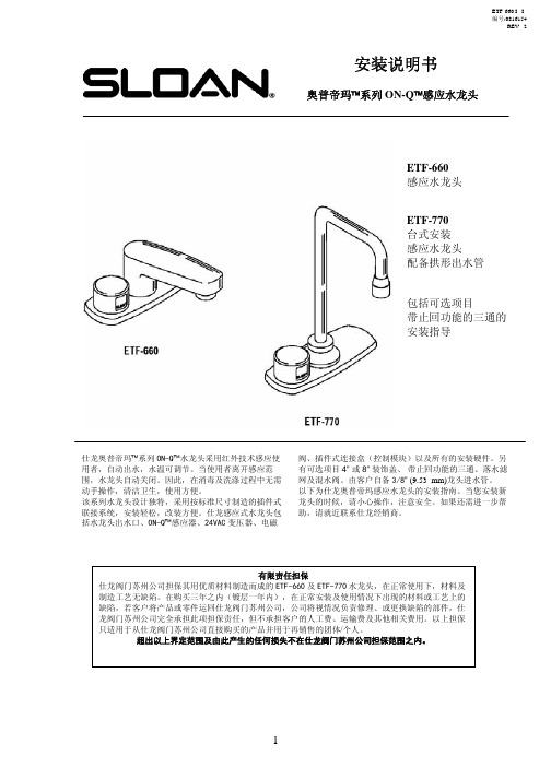
ETF-660 I . I .编号:0816154REV . 2安装说明书奥普帝玛™系列ON-Q ™感应水龙头ETF-660 感应水龙头ETF-770 台式安装 感应水龙头配备拱形出水管包括可选项目带止回功能的三通的 安装指导阀、插件式连接盒(控制模块)以及所有的安装硬件。
另有可选项目4” 或8” 装饰盖、 带止回功能的三通、落水滤网及混水阀。
由客户自备3/8” (9.53 mm)龙头进水管。
以下为仕龙奥普帝玛感应水龙头的安装指南。
当您安装新龙头的时候,请小心操作,注意安全。
如果还需进一步帮助,请就近联系仕龙经销商。
仕龙奥普帝玛™系列ON-Q ™水龙头采用红外技术感应使用者,自动出水,水温可调节。
当使用者离开感应范围,水龙头自动关闭。
因此,在消毒及洗涤过程中无需动手操作,清洁卫生,使用方便。
该系列水龙头设计独特,采用按标准尺寸制造的插件式联接系统,安装轻松,改装方便。
仕龙感应式水龙头包括水龙头出水口、ON-Q ™感应器、24VAC 变压器、电磁龙头示意图——图1ETF-660/770龙头在冷/热水供水情况下 最大流水量ETF-660/770—0.5加仑/分钟 (1.9升/分钟) ETF-660/770-B —2.0加仑/分钟 (7.6升/分钟)ETF-660/770-C —2.0加仑/分钟 (7.6升/分钟)—层流出水口ETF-660/770龙头在单冷水供水情况下 最大流水量ETF-660/770—0.5加仑/分钟 (1.9升/分钟) ETF-660/770-B —2.0加仑/分钟 (7.6升/分钟)ETF-660/770-C —2.0加仑/分钟 (7.6升/分钟)—层流出水口安装前:安装仕龙奥普帝玛系列水龙头之前,首先安装以下所列部件,如图1所示。
•使用插入式变压器——安装电源插座。
EL-233(24VAC,35VA)变压器接入120V ,2amp 交流电。
•使用盒式变压器——在安装处合理布线。
电热水龙头产品说明书
电水龙头产品说明书
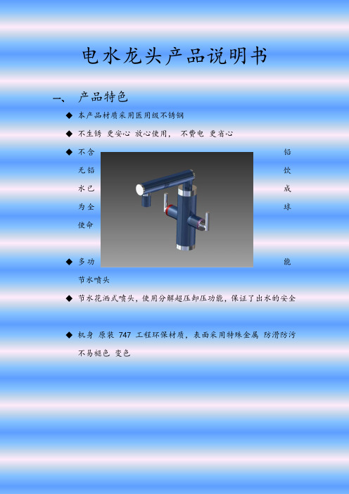
一、产品特色
◆本产品材质采用医用级不锈钢
◆不生锈更安心放心使用,不费电更省心
◆不含铅
无铅饮
水已成
为全球
使命
◆多功能
节水喷头
◆节水花洒式喷头,使用分解超压卸压功能,保证了出水的安全
◆机身原装747工程环保材质,表面采用特殊金属防滑防污
不易褪色变色
二、产品优势
◆耐高温、耐磨损、抗老化、寿命长、可经受破坏30万次,依
然开关自如可以用28年以上
◆747
工程
环保
材质,
表面
采用
特殊
金属防滑防污不易褪色变色不生锈更安心放心使用,不
费电更省心
◆不含铅无铅饮水已成为全球使命
三、装配示意图
四、售后服务
全国联保,2年保修,7天包退,30天包换。
服务热线7492541。
RU感应龙头使用说明

感应龙头产品说明书一、产品应用和功能特点具有红外自动感应功能的龙头,自动出水,可调节水温,当使用者离开感应范围,龙头自动关闭。
因此,在消毒及洗涤过程中,无需动手操作,清洁卫生,使用方便,适用于学校,宾馆酒店、写字楼、医院、商场、食品加工企业、旅游场所、需净化作业的场所等等二、技术参数三、安装方法:安装方法:1、进水口要求“左热、右冷”。
2、安装前先开启水源,务必将管道内之杂质、砂粒等清除干净,再关闭水源。
3、取出角阀并套入装饰盖,将角阀螺纹缠上生料带,拧入进水管接口,再将装饰盖旋紧并贴紧墙面。
4、将固定螺栓和两根编织软管旋入龙头体底部相应的孔中,龙头底部装入橡胶垫,再穿过台面(台盆)安装孔,将龙头体底部紧贴安装孔面,依序从台面(台盆)下方装入橡胶垫片及固定片,用固定螺帽锁紧。
5、将两根编织软管分别与角阀连接(注意:按“左热、右冷”连接)。
6、将电源盒按在台盆下方的墙面上,定好高度和位置,以¢7钻头在两圆孔内先引孔,再钻孔,深度约27mm ,用膨胀;螺钉将电源盒定于墙上。
7、打开电源盒盖子,将电线插入线路板电源插头中,再将电池正负极对准,按入电源盒,合上盖子,用自攻螺丝锁紧。
四、操作说明:开启关闭:把手放在感应区,龙头出水,移开手,龙头关闭。
冷热温度调整:将右边的手柄顺时针转动,冷水流出;手柄逆时针转动,热水流出。
感应距离调整:取出电池,等几秒钟后再装上电池,当红灯在闪的时候,把双手置于感应器正前方小于5厘米处,当红灯开的时候,把手移至你所希望的距离,当红灯关的时候,距离被储存了,就可以拿开手了。
注意:当换电池时,避免把任何物体放在小于5cm处。
五、维修及保养1.请定期将起泡器卸下加以清洗,以防止异物阻塞出水口影响出水状况。
2.处理龙头表面及感应探头表面的污垢时,请以海绵或软质的抹布,沾水加上中性清洁剂轻轻擦拭,即可保持产品亮丽光泽。
3.定期拆卸清洗进水角阀中的滤网,避免异物阻塞,影响出水状况。
六、注意事项1.请勿于阳光直接照射或强烈灯光照射处安装此电子感应器,以免造成感应器性能下降。
- 1、下载文档前请自行甄别文档内容的完整性,平台不提供额外的编辑、内容补充、找答案等附加服务。
- 2、"仅部分预览"的文档,不可在线预览部分如存在完整性等问题,可反馈申请退款(可完整预览的文档不适用该条件!)。
- 3、如文档侵犯您的权益,请联系客服反馈,我们会尽快为您处理(人工客服工作时间:9:00-18:30)。
Code No. 0816490Rev. 4 (12/10)INSTALLATION INSTRUCTIONS FOR ELECTRONIC SENSOR ACTIVATED LAVATORY FAUCETSLIMITED WARRANTYSloan Valve Company warrants its Optima EAF-275, EAF-250, EAF-225 and EAF-200 Series Electronic Hand Washing Faucets to be made of first class materials, free from defects of material or workmanship under normal use and to perform the service for which they are intended in a thoroughly reliable and efficient manner when properly installed and serviced, for a period of three years from date of purchase. During this period, Sloan Valve Company will, at its option, repair or replace any part or parts which prove to be thus defective if returned to Sloan Valve Company, at customer’s cost, and this shall be the sole remedy available under this warranty. No claims will be allowed for labor, transportation or other incidental costs.This warranty extends only to persons or organizations who purchase Sloan Valve Company’s products directly from Sloan Valve Company for purpose of resale. This warranty does not cover the life of the battery.THERE ARE NO WARRANTIES WHICH EXTEND BEYOND THE DESCRIPTION ON THE FACE HEREOF. IN NO EVENT IS SLOAN VALVE COMPANY RESPONSIBLE FOR ANY CONSEQUENTIAL DAMAGES OF ANY MEASURE WHATSOEVER.FAUCET ROUGH-IN-ISM-IC -Click Feature (All Series)-DPU -P Plug-in Transformer/Adapter (EAF-200 Series)-LTLess Transformer/Adapter (EAF-200 Series)MODELS EAF-200/250/275 ‡2.2 gpm (8.3 Lpm) Max. Flow ‡Faucets with Single Line Water SupplyEAF-250 SeriesBattery Powered, Sensor Activated Lavatory FaucetsEAF-200 SeriesAdapter Powered, Sensor Activated Lavatory Faucets®EAF-275 SeriesSolar Powered with Battery Backup Sensor Activated Lavatory FaucetsEAF-225 SeriesAdapter Powered, Sensor Activated Lavatory Faucets with TemperatureIndicating Illumination(Models shown with ISM Integral Spout Mixer)• 13 mm open end wrench or nut driver for faucet retainer nut• 3/4” open end wrench for female end of flex hosePrior to installing the Sloan Optima EAF-275/EAF-250/EAF-200/EAF-225 Series Faucets,install the items listed below. Also, refer to rough-in illustrations.•Lavatory/sink •Drain line•Hot and cold water supply lines or pre-tempered water supply line Important:•ALL PLUMBING SHOULD BE INSTALLED IN ACCORDANCE WITH APPLICABLE CODES AND REGULATIONS.•FLUSH ALL WATER LINES PRIOR TO MAKING CONNECTIONS.•KEEP THREAD SEALANT OUT OF YOUR WATERWAY TO PREVENT COMPONENT PART DAMAGE! DO NOT USE ANY SEALANT ON COMPRESSION FITTINGS.Trim PlatesWhen the EAF Faucet is installed on a sink that has three (3) hole punchings, a Trim Plate should be used. Trim Plates must be specified and ordered separately.ETF-312-A Trim Plate for 4” (102 mm) Centerset Sink ETF-510-A Trim Plate for 8” (203 mm) Centerset SinkCENTER HOLE IN DECK OR LAVATORYSENSOR LABEL23Setting Brightness of IlluminationRemove cover.Press button for approximately 5 seconds.FACTORY SETTING IS APPROPRIATE FOR THE MAJORITY OF APPLICATIONS AND SHOULD NOT REQUIRE RESETTING UNLESS UNDER EXTREME SITUATIONS.6DO NOT USE abrasive or chemical cleaners (including chlorine bleach) to clean Faucets that may dull the luster and attack the chrome or special decorative finishes. Use ONLY mild soap and water, then wipe dry with clean cloth or towel.While cleaning the bathroom tile, protect the Faucet from any splattering of cleaner. Acids and cleaning fluids willdiscolor or remove chrome plating.HOT LIMIT STOP ADJUSTMENT7... 2 xThis feature will operate the faucet every 12 or 24 hours since last use, if not used to prevent stagnant water conditions.Default purge duration is two minutes.Consult factory regarding other timing options.2A 2B 2C Item #Part #Description1EAF-14-A Faucet Sensor Assembly (EAF-275 only)EAF-19-A Faucet Sensor Assembly (EAF-200 and EAF-225 only)EAF-21-A Faucet Sensor Assembly (EAF-250 only)EAF-16-A Faucet Sensor Assembly with i.q.-Click (EAF-275 only)EAF-18-A Faucet Sensor Assembly with i.q.-Click (EAF-200 and EAF-225 only)EAF-20-A Faucet Sensor Assembly with i.q.-Click (EAF-250 only)2A EAF-1006Cap with Solar Cell Assembly (EAF-275 only)2B EAF-27Cap (EAF-250 and EAF-200 only)2C —Cap (EAF-225)3A EAF-150.5 gpm (1.9 Lpm) VR Pressure Compensating Spray Head 3B EAF-22 1.5 gpm (5.6 Lpm) Pressure Compensating Aerated Stream 3C EAF-10 2.2 gpm (8.3 Lpm) Aerator Spray Head3D EAF-13 2.2 gpm (8.3 Lpm) Laminar Flow Spray Head 4EAF-1003Battery Replacement Kit 5EAF-1Faucet Mounting Kit 6EAF-9Strainer (Filter)7A EAF-1004Mixer Handle Assembly and Cartridge 7B EAF-1005Handle Repair Kit 8EAF-1007Handle Cap9EAF-100813” (330 mm) Flexible Supply Hose 10EAF-44Power Splitter†11EAF-24-A 11-13/16” (300 mm) Extension Cable EAF-25-A 47-1/4” (1200 mm) Extension Cable EAF-17-A 126” (3200 mm) Extension Cable 12ETF-312-A Trim Plate for 4” Centerset Sink 13ETF-510-A Trim Plate for 8” Centerset Sink14EAF-11Plug-in Adapter (Models EAF-200/225)15EAF-2Solenoid† EAF-44 replaces the separate EAF-23-A Splitter Cable and EAF-28 Capacitor,which is sold separately.3A 3B 3C 3D7A7B415139126814The information contained in this document is subject to change without notice.SLOAN VALVE COMPANY • 10500 SEYMOUR AVENUE • FRANKLIN PARK, IL 60131Phone: 1-800-982-5839 or 1-847-671-4300 • Fax: 1-800-447-8329 or 1-847-671-4380 • Copyright © 2010 SLOAN VALVE COMPANYCode No: 0816490 –Rev. 4 (12/10)1110151.Problem:Faucet does not function.Cause:Adhesive packaging label affixed over sensor eye.Solution:Remove adhesive label from sensor eye.Cause:"Permanent Off" activated.Solution:Press button on faucet throat one time.2.Problem:Faucet delivers water in an uncontrolled manner.Cause:Faucet is defective.Solution:Contact the Sloan Valve Company Installation Engineering Department (see below).3.Problem:Faucet does not deliver any water when Sensor is activated.Indicator:Solenoid valve produces an audible “CLICK.”Cause:Water supply stop(s) closed.Solution:Open water supply stop(s).Cause:Water supply stop strainer(s) clogged.Solution:Remove, clean, and reinstall water supply stop strainer(s).Replace strainer(s) if required.Indicator:Solenoid valve DOES NOT produce an audible “CLICK.”Cause:Battery low (battery operated models).Solution:Replace battery (refer to Battery Replacement on Page 3).Cause:Power failure (EAF-200 Models).Solution:Check power supply.4.Problem:Faucet delivers only a slow flow or dribble when Sensor is activated.Cause:Water supply stop(s) are partially closed.Solution:Completely open water supply stop(s).Cause:Water supply stop strainer(s) clogged.Solution:Remove, clean, and reinstall water supply stop strainer(s).Replace strainer(s) if required.4.Problem:Faucet delivers only a slow flow or dribble when Sensor is activated.Cause:Aerator is clogged.Solution:Remove, clean, and reinstall Aerator. Replace Aerator if required.Cause:Faucet is defective.Solution:Contact the Sloan Valve Company Installation Engineering Department (see below).5.Problem:Faucet does not stop delivering water or continues to drip after user is no longer detected.Cause:Valve is defective.Solution:Contact the Sloan Valve Company Installation Engineering Department (see below).6.Problem:LED indicator blinks when faucet is in use.Cause:Battery low (battery operated models).Solution:Replace battery (refer to Battery Replacement on Page 3).7.Problem:The water temperature is too hot or too cold on a faucet connected to hot and cold supply lines.Cause:Supply Stops are not adjusted properly.Solution:Adjust Supply Stops.Cause:For models with integral mixing valve — Mixing valve is set improperly for the water temperature desired.Solution:Rotate mixing valve handle clockwise to decrease water temperature or counterclockwise to increase water temperature.When assistance is required, please contact Sloan Valve Company InstallationEngineering Department at:1-888-SLOAN-14 (1-888-756-2614)。