EK变频器手册
科肯H100A系列用户手册中文版
简介感谢您购买广州科肯电气有限公司生产的H100A 系列简易型变频器!H100A 实现了高转矩、高精度、宽调速驱动,满足通用变频器高性能化的趋势;具有超出同类产品的防跳闸性能和适应恶劣电网、温度、湿度和粉尘能力,极大提高产品可靠性。
灵活的输入输出端子、停电和停机参数存储选择、频率给定通道、主辅给定控制等,满足各种复杂高精度传动的要求,同时为设备制造业客户提供高集成度的一体化解决方案,对降低系统成本,提高系统可靠性具有极大价值。
本手册提供用户选型、安装配线、面板操作、参数设定、故障诊断等事项。
为确保能正确安装及操作H100A 系列变频器,请在装机之前,详细阅读本使用手册,并请妥善保存及交给本产品的使用者。
产品到货后在开箱时,请认真确认以下项目:1)本机铭牌的型号是否与您的订货一致。
箱内含您订购的机器、产品合格证、用户操作手册。
2)产品在运输过程中是否有破损现象;若发现有遗漏或损坏,请速与本公司或您的供货商联系解决。
由于致力于变频器的不断改善,因此本公司所提供的资料如有变更,恕不另行通知。
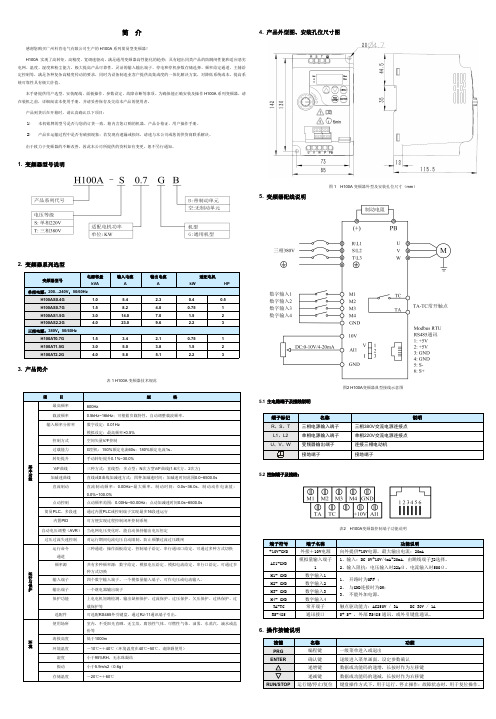
1.变频器型号说明2.变频器系列选型3.产品简介表1H100A 变频器技术规范4.产品外型图、安装孔位尺寸图图1H100A 变频器外型及安装孔位尺寸(mm )5.变频器配线说明图2H100A 变频器典型接线示意图5.1主电路端子及接线说明5.2控制端子及接线:表2H100A 变频器控制端子功能说明6.操作按键说明功能表中符号说明如下:“☆”:表示该参数的设定值在变频器处于停机、运行状态中,均可更改;“★”:表示该参数的设定值在变频器处于运行状态时,不可更改;“●”:表示该参数的数值是实际检测记录值,不能更改;。
欧科变频器说明书文档

欧科变频器说明书文档(总8
页)
-CAL-FENGHAI.-(YICAI)-Company One1
-CAL-本页仅作为文档封面,使用请直接删除
欧科变频器的P01基本功能组,主要有以下功能:控制模式;运行指令信道;编码器及端子递增+/递减-设定;频率指令选择;转矩设定方式选择;键盘设定转矩;上限频率设定源选择;最大输出频率;运行频率上限;运行频率下限;键盘设定频率;加速时间1;减速时间1;运行方向选择;载波频率设定;功能参数恢复;AVR功能选择
P01组基本功能组
启动运行方式;启动开始频率;启动频率保持时间;启动前制动电流;启动前制动时间;停机方式选择;停机制动开始频率;停机制动等待时间;停机直流制动电流;停机直流制动时间;正反转死区时间;上电端子运行保护选择;预留
欧科变频器P02启停控制组主要具有以下功能:启动运行方式;启动开始频率;启动频率保持时间;启动前制动电流;启动前制动时间;停机方式选择;停机制动开始频率;停机制动等待时间;停机直流制动电流;停机直流制动时间;正反转死区时间;上电端子运行保护选择;预留
P02组启停控制组。
科力尔变频器说明书

科力尔变频器说明书第一章概述1.1产品概述科力尔变频器是一种电力调速设备,通过改变电机输入电压和频率,实现电机转速的调整,从而实现功率输出的调节。
科力尔变频器具有体积小、重量轻、效率高、控制精度高等优点,广泛应用于机械设备、通风设备、水泵设备等领域。
1.2使用范围1.3技术参数-输入电压:AC220V/380V/440V-频率范围:50Hz/60Hz-输出电压:0-100%可调-功率范围:0.4kW-315kW-控制方式:V/F控制,矢量控制-控制精度:±0.5%-负载类型:恒转矩负载、恒功率负载、恒电流负载第二章使用前准备2.1安装前准备在安装科力尔变频器前,请确保以下准备工作已完成:-确保供电电压和频率与变频器参数符合-安装变频器的位置应通风良好,避免高温和潮湿环境-确保电机与变频器的电缆连接正确并牢固-安装过程中,应按照变频器安装手册操作,避免损坏设备2.2接线前准备在接线前,请确保以下准备工作已完成:-根据电机和变频器的额定电压和功率,选择合适的电缆和接线端子-确保电缆与接线端子之间的连接牢固可靠-避免电缆过长,造成电压损失和干扰-检查接线端子是否正确固定,避免松动引起故障第三章使用说明3.1启动与停止-启动变频器时,请先打开供电开关,然后按下启动按钮-停止变频器时,请按下停止按钮,然后关闭供电开关3.2电机调速-以V/F控制方式为例,通过调节变频器的输出电压和频率,实现电机转速的调整-可通过面板上的旋钮、按键、数字输入等方式进行设置-也可以通过远程控制面板或上位机软件进行参数设置和调整3.3故障排除变频器使用过程中可能出现的故障包括过载、短路、过热等。
当出现故障时,应按照以下步骤进行排除:-关闭变频器的供电开关-检查电机和变频器的连接情况,是否有异常现象-检查变频器的参数设置,是否合理第四章维护与保养4.1清洁与防尘定期清洁变频器表面,避免灰尘和杂质进入设备内部,影响散热和正常运行。
英飞克E3系列变频器说明书-Ver2.04

E
标注为AI1、AI2) CCI(AI1)
J4
Rs485
GND
通讯
61
(MINI机型通讯接口为专用网口)
1 +15V 2 GND 3 RS485+ 4 RS4855-6 NC
-11-
R(L1) S T(L2) E U V W P+ PB
E
PB
MINI机型为B1、B2
NC TA1 TB1 TC1 TA2 TB2 TC2
………………………………………………………………… 83 ………………………………………………………… 84
………………………………………………………………… 87 …………………………………………………… 87
………………………………………………………………… 92 ……………………………………………………… 92 …………………………………………… 93
-12-
NC NC
X6
NC
备注:MINI机型不提供X6、X7端子。 备注:MINI机型AI1为CCI,AI2为VCI。 备注:MINI机型只提供一路模拟输出。
-13-
备注:MINI机型只提供一路继电器输出。 备注:(MINI机型通讯口 采用专用网线接口)
不可将交流输入电源接到变频器输出端子U、V、W。 在变频器U、V、W输出端不可以加装进相电容或阻容吸收装置。
E3-0030P/0030A-T4
E3-0037P/0037A-T4 E3-0045P/0045A-T4 E3-0055P/0055A-T4
E3-0075A-T4
E3-0075P-T4
E3-0090A-T4
E3-0090P-T4
E3-0110A-T4
e-key 300系列手册 使用说明书
EKS Profinet on Siemens S7-300 – reading in EKS Electronic-KeysContentsComponents/modules used (2)EUCHNER (2)Others (2)Functional description (2)General (2)Example of an Electronic-Key structure (2)Setting the EKS Electronic-Key adapter (3)Profinet addressing (3)Write-protection setting (3)Configuration in the control system (4)Hardware (4)Programming in the control system (6)Global data blocks (6)STL program for retrieving the Electronic-Key content (7)Important note – please observe carefully! (10)Components/modules usedEUCHNERDescription Order no./item designationEKS Profinet 106305 / EKS-A-IIX-G01-ST02/03EKS Electronic-Key 077859 / EKS-A-K1RDWT32-EU084735 / EKS-A-K1BKWT32-EU091045 / EKS-A-K1BLWT32-EU094839 / EKS-A-K1GNWT32-EU094840 / EKS-A-K1YEWT32-EUTip: More information and downloads about the aforementioned EUCHNER products can be found at www.EUCHNER.de. Simply enter the order number in the search box.OthersDescription ItemS7-300, CPU 315F-2 PN/DP 6ES7315-2FJ14-0AB0Functional descriptionGeneralThe EKS is connected to a Siemens S7-300 PLC via the Profinet. All data corresponding to the data structure below should be read out.Example of an Electronic-Key structureThe data on the Electronic-Key are structured as follows:Byte no. Description Type Length Explanation103 – 104 KEYCRC CRC 2 bytes Checksum over a certain part of the Electronic-Key as copy protection.Refer to the EKM manual for details about the CRC.105 – 112Expiry date Date 8 bytes Electronic-Key expiry date.113 – 114 Authorization level Word 2 bytes Authorization level for access to the machine.115 Department Byte 1 byte Number describing a limited quantity of machines or installations.116 – 123 KeyID KeyID 8 bytes The KeyID is a number that is permanently pre-programmed on theElectronic-Key by EUCHNER. This number is different for each Electron-ic-Key. This number can be used to identify workers.The structure corresponds to application example AP000169-2…Setting the EKS Electronic-Key adapterProfinet addressingThe device is to receive the address via the Siemens configuration software Simatic Manager. Accordingly, all switches are set to OFF on DIP switch S2.Figure 1The device is to receive the DCP name via the Siemens configuration software Simatic Manager. Accordingly, all switches are set to OFF on DIP switch S3.Figure 2Write-protection settingThe device is configured only for reading. Correspondingly, DIP switch S1.1 is set to ON.Figure 3Configuration in the control systemHardwareSimatic Manager version 5.5+SP1 is used for configuration. To perform parameter assignment for the EKS on Profinet drag the object “EKS-A-IIX-G01-ST02/03” to the Profinet. The address range can remain set at 256 to 383.When a new Electronic-Key is inserted, the data are always read automatically from byte 0. As the user data are at the end of the Electronic-Key instead of at the beginning in this example, the actual user data are restricted. Nevertheless, a 128-byte range always must be provided in the input.Figure 4Set the DCP name and the device number in the properties of the EKS Profinet. The default name “EKS-PN” and the device number 1 are used in this example.Figure 5An update time of longer than 128 ms must be set in the object properties on the “IO Cycle” tab in the “Interface” slot of the EKS Profinet.Figure 6The alarm settings will not be addressed in this example.Under the object properties on the “Parameters” tab in the “Read: 128 bytes” slot, it is set that the user data are to be retrieved with a length of 21 bytes from start address 103. The 21 bytes consist of the user data with a length of 13 bytes and the KeyID with a length of 8 bytes. They are therefore retrieved together and stored from data byte 1 in the input range. The status word of the EKS Profinet is located in data byte 0 of the input range.Figure 7Programming in the control systemGlobal data blocksA data block is created for saving the received data for the EKS.The data are created in a structured manner in the data block for reading, with all data items longer than one byte being created as individual bytes to circumvent the even-numbered alignment in the control system. The data block must be the same length as the input range of the EKS, otherwise the system function for reading will not work.DB1, ReadBufferEKSFigure 8DB10, instance module for FB1As the function module FB1 operates with static variables, a DB must be used as an instance module. In the example, DB10 is created for this purpose.STL program for retrieving the Electronic-Key contentThe reading program is programmed in FB1 in this example. The program reads only when an Electronic-Key is inserted and new data are ready. An Electronic-Key that has been read in once will not be read in again. The data from byte 103 (KeyCRC), including the KeyID, are read and are provided in data block DB1 from byte 1 for further processing. 21 bytes of user data in total are re-trieved from the EKS Electronic-Key.The status bye of EKS is saved in byte 0 DB1.Description of the interfaceInput dataNone.Output dataError message, new Electronic-Key and status of the DP slave.Input/output dataNone.Static dataThe KeyRead marker is created statically. This marker identifies whether an Electronic-Key has already been completely read one time. Data are retrieved only if the marker is not set. The marker is reset whenever there is no longer an Electronic-Key in the EKS. Temporary dataNone.Changed registersA1, A2, SWUnchanged registersAR1, AR2, DBR1, DBR2System functions usedSFC14, DPRD_DAT – read standard DP slaves/PROFINET IO devicesGlobal dataData block DB1 with a minimum size of 128 bytes is assumed.The content of data block DB1 is completely overwritten.Symbol tableFigure 10STL program in FB1- ReadEKS//Retrieval of data from the EKS Electronic-Key// Check of whether an Electronic-Key was inserted, and data retrieval only if this is the caseU "EKSIn" // Check whether an Electronic-Key is insertedSPB MKEY // If inserted, check whether data have already been retrieved R #KeyRead // Mark that a new Electronic-Key can now comeSPA MRET// Electronic-Key is inserted// Check whether the Electronic-Key is newMKEY: U #KeyRead // If KeyRead is set, this Electronic-Key has already been read SPBN MRD // Retrieve data only from new Electronic-Key// No new Electronic-Key inserted, no errorMRET: R #Error // Feedback, no errorR #NewKey // Feedback, no Electronic-KeyBEFigure 11a// Reading of data from EKS into DB1MRD: CALL "DPRD_DAT" // Call of SFC 14 DPRD_DATLADDR :=W#16#100 // Address of the EKS memory rangeRET_VAL:=MW1 // FeedbackRECORD :=P#DB1.DBX0.0 BYTE 128 // Start address of the DB for reception, length must be 32// Check whether an error occurredL MW 1L 0 // Only return value 0 is OK==ISPBN MERR // If a value <> 0 was returned in marker word 1: error// Electronic-Key read completely, the data are now in DB1S #KeyRead // Note that reading was complete with this counter valueS #NewKey // Report back that a new Electronic-Key was read completelyR #Error // No errorsBEFigure 11b// Error processingMERR: L MW 1 // DP status as feedback in case of errorT #DPStatusS #Error // Return value = 1, error occurredR #NewKeyBEFigure 11cFB1 call//Retrieval of data from the EKS Electronic-KeyCALL "Read EKS" , "Data FB1"Error :=M0.0 // Return value for errorNewKey :=M0.1 // Return value, whether new Electronic-Key DPStatus:=#Status // Status of the DP slaveU M 0.0 // Check whether error occurredSPB MERR // If values = 1, jump to error routine Figure 12Important note – please observe carefully!This document is intended for a design engineer who possesses the requisite knowledge in safety engineering and knows the ap-plicable standards, e.g. through training for qualification as a safety engineer. Only with the appropriate qualification is it possible to integrate the introduced example into a complete safety chain.The example represents only part of a complete safety chain and does not fulfill any safety function on its own. In order to fulfill a safety function, the energy switch-off function for the hazard location and the software within the safety evaluation must also be considered, for example.The introduced applications are only examples for solving certain safety tasks for protecting safety doors. The examples cannot be comprehensive due to the application-dependent and individual protection goals within a machine/installation.If questions concerning this example remain open, please contact us directly.In accordance with Machinery Directive 2006/42/EC, the design engineer of a machine or installation is obligated to perform a risk assessment and take measures to reduce the risk. When doing this, the engineer must comply with the applicable national and international standards. Standards generally represent the current state of the art. Therefore, the design engineer should continu-ously inform himself about changes in the standards and adapt his considerations to them. Relevant standards include EN ISO 13849 and EN 62061. This application must be regarded only as assistance for the considerations about safety measures.The design engineer of a machine/installation is obligated to assess the safety technology itself. The examples must not be used for assessment, because only a small excerpt of a complete safety function was considered in terms of safety engineering here. In order to be able to use the safety switch applications correctly on safety doors, it is indispensable to observe the standards EN ISO 13849-1, EN ISO 14119 and all relevant C-standards for the respective machine type. Under no circumstances does this doc-ument replace the engineer’s own risk assessment, and it cannot serve as the basis for a fault assessment.Particularly in case of fault exclusion, it must be noted that this can be performed only by the design engineer of a machine or installation and requires a reason. General fault exclusion is not possible. More information about fault exclusion can be found in EN ISO 13849-2.Changes to products or within assemblies from third-party suppliers used in this example can lead to the function no longer being ensured or the safety assessment having to be adapted. In any event, the information in the operating instructions on the part of EUCHNER, as well as on the part of third-party suppliers, must be used as the basis before this application is integrated into an overall safety function. If contradictions should arise between the operating instructions and this document, please contact us directly.Use of brand names and company namesAll brand names and company names stated are the property of the related manufacturer. They are used only for the clear identifi-cation of compatible peripheral devices and operating environments in relation to our products.EUCHNER GmbH + Co. KG · Kohlhammerstraße 16 · 70771 Leinfelden-EchterdingenTelephone:+497117597-0·Fax:+497117597-303·***************·www.euchner.de。
艾瑞克变频器说明书

艾瑞克電機(深圳)有限公司EI-700 MODBUS PROTOCOL目錄1. 通信之相關參數---------------------------------------------------11.1傳送ERROR時的處理-------------------------------------------22. 傳送順序------------------------------------------------------------3 2.1訊息的組成----------------------------------------------------------3 2.2 SLA VE的應答----------------------------------------------------4-52.3信號傳送所需的時間----------------------------------------------63. MESSAGE FORMAT---------------------------------------------7 3.1保持暫存的內容讀出----------------------------------------------7 3.2向複數保持暫存器輸入-------------------------------------------8 3.3 ENTER指令--------------------------------------------------------9 3.4常數輸入之順序---------------------------------------------------10 3.5 Loop Back Test〔08H〕------------------------------------------113.6 CRC-16的計算----------------------------------------------------12-134 保持暫存器編號一覽表------------------------------------------14-231.通信之相關參數Master通信之前,EI-700之通信相關參數必須先設定,特別是F5-01~F5-05在與Master 第一次通信前必須先設定。
emerson EV-ECD03-4T0110变频器说明书
Emerson EV-ECD03-4T0110变频器说明书产品参数:名称:Emerson EV-ECD03-4T0110变频器品牌:Emerson/艾默生型号:EV-ECD03-4T0110额定电压:380V~440V频率:50Hz/60HzEmerson EV-ECD03-4T0110变频器安装说明:1、变频器应安装在室内、通风良好的场所,一般应垂直安装。
2、选择安装环境时,应注意以下事项:环境温度要求在-10℃~40℃的范围内,如温度超过40℃时,需采取散热措施或者降额使用;湿度要求低于95%,无水珠凝结;安装在振动小于5.9米/秒的场所;避免安装在阳光直射的场所;避免安装在多尘埃、金属粉末的场所;严禁安装在有腐蚀性、爆炸性气体场所;3、安装间隔及距离要求,当两台变频器采用上下安装时,中间应用导流隔板。
Emerson EV-ECD03-4T0110变频器运行方式:Emerson EV-ECD03-4T0110变频器运行方式分为五种,按优先级依次为:点动运行>闭环运行>PLC运行>多段速度运行>普通运行。
1、点动运行:变频器在停机状态,接到点动运行命令后,按点动频率运行。
2、闭环运行:闭环选择功能有效,变频器将选择闭环运行方式,即按照给定和反馈量进行PI调节。
通过多功能端子可将闭环运行方式失效,切换为较低级别的运行方式。
3、PLC运行:PLC功能有效,变频器将选择PLC运行方式,变频器按照预先设定的运行方式运行。
通过多功能端子将PLC运行方式失效。
4、多段速度运行:通过多功能端子的非零组合,选择多段频率1~7进行多段速运行。
5、普通运行:简单的开环运行方式。
EK变频器手册
使用本章节说明驱动器到货时以及安装时的确认事项。
■IMS-GL3的介绍..........................................................................................1-1■产品到货时的确认.......................................................................................1-2■外型尺寸安装尺寸.....................................................................................1-4■安装场所的确认和管理...............................................................................1-5■安装方向和空间...........................................................................................1-6■IMS-GL3的介绍IMS-GL3的机种IMS-GL3系列驱动器电源等级为400V 级。
适用电机容量为5.5~45KW (共9机种)。
表1.1 400V 级机种容量的规格型号IMS-GL3-□ 45P547P54011401540184022403040374045驱动器容量代码 45P547P540114015401840224030 4037 4045最大适用电机功率(KW) 5.5 7.5 11 15 18.522 30 37 45 输出功率(KVA) 11 16 21 26 32 40 50 61 74 额定输出电流(A) 15 21 27 34 42 52 658097(W) 800100015002000400060009600 12800 16000制动电阻的选择 10075 50 40 32 20 1613.6 11 最小适配电阻值 (Ω)39 39 26 26 20 20 13 1010 断路器的选择(A) 20 30 50 60 75 100100 100150 接触器的选择(A) 20 20 30 50 50 50 80 80 100 (A) 15 20 30 50 60 80 100120160 滤波器的选择(mH) 1.42 1.060.70.420.360.260.24 0.180.16■产品到货时的确认铭牌说明在驱动器侧面贴有铭牌,记载了驱动器的型号,输入输出参数、机身编号等。
科尼变频器中英文手册
HU4.07.0067 En Cn Owner’s Manual
Page 2 / (52)
用户手册
CONTENTS 目录
1 GENERAL 总则 ...................................................................................................................... 3
2. Verify all of the connections are in accordance to the drawings. 确认所有的连接跟图纸是一致.
3. Verify the motor supply is connected correctly, faulty connection will destroy the inverter. 确认马达的动力线连接正确.错误的连接会损坏变频器.
8. Do not touch the components on the circuit boards. Static voltage discharge may cause damage or destroy the IC-circuits. 不要用手接触电路板的元器件.系统的固有电压放电可能会损坏 IC 电路.
1.9.1 Fulfilled EMC-standards 现行的 EMC 标准 .................................................... 17
2 START-UP PROCEDURE 启动步骤 .................................................................................... 209
意科变频器使用指南
M0069--M072
温度
电机参数
说明
参数值
C008
额定电源电压
C010
控制算法类型
C013
V/F模式类型
C015
电机额定功率
C016
电机额定转速
C017
额定功率
C018
电机额定电流
C019
电机额定电压
C028
电机最小转速
C029
电机最大转速
C185
停机模式
参数
说明
参数值
P009
设置加速时间
根据实际情况设置
P010
设置减速时间
根据实际情况设置
过载参数
P350
3 ANALOG
P351
A65 电流有效值
P353
≥
P355
A 设定过载值
P358
1 TRUE
C164a
2000 延时2S报警
过压欠压参数
P359
4 DOUBLE ANALOG
P360
A68 直流环节电压
P361
A68 直流环节电压
P362
≤
P363
≥
P364
V
P365
V
P366
2 (A)AND(B)
P367
1 TRUE
C165a
2000 延时2S报警
设置以下参数:
参数
说明
参数值
C010
控制算法
1:VTC
C017
马达额定功率
根据电机决定
C018
马达额定电流
根据电机决定
第三步: 自动调谐
进入自动调谐菜单(Autotune Menu)
- 1、下载文档前请自行甄别文档内容的完整性,平台不提供额外的编辑、内容补充、找答案等附加服务。
- 2、"仅部分预览"的文档,不可在线预览部分如存在完整性等问题,可反馈申请退款(可完整预览的文档不适用该条件!)。
- 3、如文档侵犯您的权益,请联系客服反馈,我们会尽快为您处理(人工客服工作时间:9:00-18:30)。
使用本章节说明驱动器到货时以及安装时的确认事项。
■IMS-GL3的介绍..........................................................................................1-1■产品到货时的确认.......................................................................................1-2■外型尺寸安装尺寸.....................................................................................1-4■安装场所的确认和管理...............................................................................1-5■安装方向和空间...........................................................................................1-6
■IMS-GL3的介绍
IMS-GL3的机种
IMS-GL3系列驱动器电源等级为400V 级。
适用电机容量为5.5~45KW (共9机种)。
表1.1 400V 级机种容量的规格
型号IMS-GL3-□ 45P547P540114015401840224030
4037
4045
驱动器容量代码 45P5
47P5
4011
4015
4018
4022
4030 4037 4045
最大适用电机功率(KW) 5.5 7.5 11 15 18.522 30 37 45 输出功率(KVA) 11 16 21 26 32 40 50 61 74 额定输出电流(A) 15 21 27 34 42 52 65
80
97
(W) 8001000
1500
2000
4000
6000
9600 12800 16000
制动电阻的选择 100
75 50 40 32 20 16
13.6 11 最小适配电阻值 (Ω)
39 39 26 26 20 20 13 10
10 断路器的选择(A) 20 30 50 60 75 100
100 100
150 接触器的选择(A) 20 20 30 50 50 50 80 80 100 (A) 15 20 30 50 60 80 100
120
160 滤波器的选择
(mH) 1.42 1.06
0.7
0.42
0.36
0.26
0.24 0.18
0.16
■产品到货时的确认
铭牌说明
在驱动器侧面贴有铭牌,记载了驱动器的型号,输入输出参数、机身编号等。
铭牌举例
以三相AC 400V 11KW规格为例:
MODEL:驱动器型号
INPUT:输入电源参数
OUTPUT:驱动器输出参数
SER NO:机身编号
MASS:重量
图1.1 铭牌
1-3 驱动器型号说明
在铭牌上的驱动器型号『MODEL 』一栏里用数字和字母表示了驱动器的系列号、电压等级、最大适用电机容量以及改版记号。
图1.2 变频器的型号
各部分的名称
图1.3所示为IMS-GL3机体的外观。
图1.3驱动器外观
■外型尺寸安装尺寸
以下所示为驱动器的外形图
图1.4 驱动器的外型图
表1.3驱动器的外型尺寸(mm)和毛重(kg)
型号IMS-GL3-□45P5 47P5401140154018402240304037 4045
W 248 248248248248260260380 380
H 328 328328328328328328495 495
安装尺寸(mm)
D 180 180180180180179179250 250
W1 188 188188188188188188325 325
H1 311 311311311311311311480 480 重量(kg) 9 9 9 9 9 12 12 32 32
■安装场所的确认和管理
在如下条件的场所安装驱动器,并维持最适当的使用条件。
安装场所
请安装在满足以下条件的场所:
环境温度:-10~40℃
环境湿度:90%RH(不结露)
·请勿安装在金属粉末、油、水等容易进入驱动器内部的场所。
·请勿安装在有木材等易燃物的场所。
·请勿安装在阳光直射的场所。
·请安装在无油雾、灰尘、清洁的场所,或安装在浮游物不能侵入的全封闭柜内。
·请安装在无放射性的场所。
·请安装在无有害气体及液体的场所。
·请安装在振动小的场所。
·请安装在盐分少的场所。
周围温度管理
为提高可靠性尽可能安装在温度不易上升的场所,安装在封闭的箱体内时,请安装冷却风扇或冷却空调,将温度控制在45℃以内。
作业时防止异物落入
安装作业时,请在驱动器上面盖上防尘罩,注意切勿使钻孔铁屑等残余金属落入驱动器内部。
安装作业结束时,请拆下驱动器上盖的防尘罩,提高通气性和驱动器的散热性。
■安装方向和空间
为不降低驱动器的冷却效果,请务必按纵向安装,并按下图所示确保一定的空间。
MOTOR
CONTROLLER
30mm以上30mm以上
图1.5 变频器的安装方向和空间
请确保主回路接线的空间。
重要。