COMPOSITE JOINTS UNDER INCREMENTAL TENSILE LOADING
science
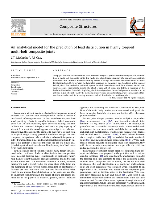
An analytical model for the prediction of load distribution in highly torqued multi-bolt composite jointsC.T.McCarthy ⇑,P.J.GrayMaterials and Surface Science Institute,Department of Mechanical and Aeronautical Engineering,University of Limerick,Irelanda r t i c l e i n f o Article history:Available online 25September 2010Keywords:Composites Bolted jointsAnalytical model Clearance Frictiona b s t r a c tThis paper presents the development of an enhanced analytical approach for modelling the load distribu-tion in multi-bolt composite joints.The model is a closed-form extension of a spring-based method,where bolts and laminates are represented by a series of springs and masses.The enhancement accounts for static friction effects between the laminates,a primary mechanism of load transfer in highly torqued bolted joints.The method is validated against detailed three-dimensional finite element models and where possible,experimental results.The effect of varying bolt-torque and bolt-hole clearance on the load distribution in a three-bolt,single-lap joint is investigated and the method proves to be robust,accu-rate and highly efficient.Finally,the method is employed in a parameter study,where increasing bolt tor-que levels can be used for achieving a more even load distribution in multi-bolt joints.Ó2010Elsevier Ltd.All rights reserved.1.IntroductionIn composite aircraft structures,bolted joints represent areas of localised stress concentration and experience a minimal amount of mechanical softening compared to their metal counterparts.Save small plasticity effects in metallic fasteners,bolted composite joints can fail catastrophically upon excessive loading and tend to limit the structural integrity and load-carrying capacity of aircraft.As a result,the overall approach to design tends to be over conservative,thus causing the composite material to detract from its original weight-saving potential.Inefficient design practices compound this problem,where solutions to bolted joint problems suffer from long lead times and high financial expenditure.In this paper,this problem is addressed through the use of a simple ana-lytical design tool,which can be used for the analysis of load trans-fer in multi-bolt joints.In the design of bolted composite joints,many design variables need to be considered.Such variables include fastener position,joint material,fastener type (countersunk or protruding head),hole diameter,joint thickness,bolt-hole clearance and bolt torque.Friction forces exist at each contact interface in joints,however,most of the load is transferred at the shear plane of the joint,and the magnitude of this force is highly dependant on bolt torque or fastener pre-load.Bolt-hole clearance and friction effects often result in an unequal load distribution in the joint,and are thus an important consideration in the design of multi-bolt joints.The main aim of this paper is to produce a generic,yet cost-effective approach for modelling the mechanical behaviour of the joint.Most of the main design variables are considered,with particular focus on varying bolt-hole clearance and friction effects between jointed members.Current joint design practices involve analytical approaches [1–4],experimental tests [5–7]and three-dimensional finite element (3-D FE)analysis [8–14].In detailed 3-D FE models,each part of the joint is modelled separately,while contact models with tight contact tolerances are used to model the interaction between each part.Such models capture effects such as clearance,bolt-torque and detailed contact stresses [8–10],friction effects between discrete regions in the joint [11],the load distribution in multi-bolt joints [12]and material damage propagation [13,14].While such models provide accurate solutions for small joint specimens,they suffer from excessive computation time,especially where friction and damage models are present.Regarding more efficient design practices,simplified finite ele-ment models have been proposed in the past.One such technique was due to Friberg [15],who used linear beam elements to model the fastener and shell elements to model the composite plates.Coupled with a simplified contact model,the method was used to simulate the load distribution in a multi-row,multi-column joint and good agreement was obtained when compared to an experimental test.However,this model omitted important joint parameters,such as friction between the laminates.This issue was later addressed by Ekh and Schön [16],who used beam elements to model both the bolt and the laminates,while bolt-hole clearance and friction effects were captured through the use of connector elements.While excellent agreement was obtained with experimental and numerical results,this approach was limited to0263-8223/$-see front matter Ó2010Elsevier Ltd.All rights reserved.doi:10.1016/pstruct.2010.09.017Corresponding author.Tel.:+35361234334;fax:+35361202944.E-mail address:conor.mccarthy@ul.ie (C.T.McCarthy).single-column joints.To capture the full mechanical behaviour in three dimensions,Gray and McCarthy[17]used shell elements to model the laminates and a combination of rigid contact surfaces and beam elements to model the bolt.Bolt-hole clearance effects and joint friction were included and again good correlation was obtained with experimental and numerical results for multi-bolt joints.Alternative,cost-effective techniques have also been proposed for the efficient design of bolted composite joints.These include boundary element formulations[18],boundary collocation meth-ods[19,20]and semi-empirical approaches[21].Barut and Madenci [22]proposed a semi-analytical model for elastic stress analysis of bolted-bonded,single-lap joints.For the design optimisation ofbenchmark studies in the EU Framework5project BOJCAS(Bolted Joints in Composite Aircraft Structures)[23]and were designed to fail initially in the bearing mode.The joints were fabricated using a carbonfibre/epoxy composite material manufactured by Hexcel composites,with designation HTA/6376.Both laminates had a qua-si-isotropic lay-up with stacking sequence[45/0/À45/90]5s.Each ply had a thickness of0.13mm,yielding a total laminate thickness of5.2mm.The unidirectional lamina material properties are listed in Table1.However,for this study the material was modelled using homogeneous material properties,which were obtained by McCar-thy et al.[9]and are also listed in Table1.The8mm diameter bolts were made from aerospace grade Titanium alloy and the material properties are,again,listed in Table1.288 C.T.McCarthy,P.J.Gray/Composite Structures93(2011)287–298take-up is clearly visible.It transpires that this delay is approxi-mately equal to the bolt-hole clearance,as would be expected (however,bolt tipping also adds to this displacement).In the highly torqued(16N m)joint,this‘‘delay in load take-up”or ‘‘clearance”effect occurs at a much higher load level,as can be seen in more detail in Fig.2b.The initial quasi-linear region,designated Slope1,is due to the joint load being reacted solely by static fric-tion forces acting at the shear plane.With increased joint load, these static friction forces are overcome,and the laminates begin to slip relative to each other.During this phase,designated the Transition Region,the large bolt-hole clearance is taken up and the bolt shank begins to contact the laminates.When significant contact is established between the bolt and the laminates,the bolt starts to transmit load and the stiffness of the joint increases signif-icantly.This region is identified as the Slope2region in Fig.2b.For all the joints considered in Fig.2a,these friction and clearance load variations occur early in the loading history and have a significant effect on the bearing strength of the joint(i.e.where the curves deviate from linearity at approximately16kN and upwards).In multi-bolt joints,these effects can be even more severe as a delay in load take-up at a particular bolt results in other bolts compen-sating for it,which in-turn may cause an already highly loaded bolt-hole region to fail catastrophically[6].This redistribution of joint load is discussed in this paper,where the non-linear elastic behaviour of joints is considered in the load distribution analysis. Joint failure will be considered in a future publication of this method.3.Model development3.1.The spring-based methodMcCarthy et al.[4]idealised bolted joints as a simple spring-mass system,an example of which is illustrated in Fig.3.The three-bolt,single-lap joint in Fig.3a may be represented by a sys-tem of springs and masses,as shown in Fig.3b.This approach is applicable to any number of in-line bolts and also double-lap joint configurations.The stiffness of the region designated‘‘Laminate1”is represented by K LAM1_END,(i.e.the spring stiffness between masses6and7),K LAM1_1and K LAM1_2.A similar convention is also used for the lower laminate,designated‘‘Laminate2”.The bolt stiffnesses are designated K BOLT1,K BOLT2and K BOLT3and represent the stiffness of Bolts1–3,respectively.The joint load,P is applied at Mass7,and reacted at the gripped end of the joint.Finally,anal-ysis of the spring-mass system is also based on the following assumptions[4]:The masses(1–7)are free to move in the x-direction only.The springs have stiffness in the x-direction only.When considering double-lap joints,only half the spring stiff-ness for Laminate1and half the total joint load(P)are used.It is also assumed by McCarthy et al.[4]that friction effects are negligible.However,the aim of this paper is to extend the current modelling strategy to account for static friction effects.McCarthy et al.[4]examined each mass in the system using free-body diagrams and equations of motion.For example,a free-body diagram for Mass 4is illustrated in Fig.4a and its correspond-ing equation of motion may be written as:m €x 4ÀK LAM 12x 2ÀK BOLT 2x 3þðK LAM 12þK BOLT 2þK LAM 11Þx 4ÀK LAM 11x 6¼K BOLT 2c 2ð1Þwhere x i is the x -displacement of Mass i (i =2,3,4,6),c 2is the bolt-hole clearance at Bolt 2and €x 4is the acceleration of Mass 4.In thisapproach only the static response of the joint is considered and so,the nodal accelerations are set to zero (i.e.€x 4¼0in Eq.(1)).Ignor-ing dynamic effects and carrying out a similar analysis for the remaining masses yields a system of linear equations of the type:½K f x g ¼f F gð2Þwhereandf xg ¼x 1x 2x 3x 4x 5x 6x 78>>>>>>>>>>>>><>>>>>>>>>>>>>:9>>>>>>>>>>>>>=>>>>>>>>>>>>>;;f Fg ¼ÀK BOLT 3c 3K BOLT 3c 3ÀK BOLT 2c 2K BOLT 2c 2ÀK BOLT 1c 1K BOLT 1c 1P8>>>>>>>>>>>>><>>>>>>>>>>>>>:9>>>>>>>>>>>>>=>>>>>>>>>>>>>;In double-lap joints,the stiffness of each bolt,defined here as K BOLT ,was derived by Tate and Rosenfeld [1]and Nelson et al.[3]:1K BOLT¼2t LAM 2þt LAM 13G BOLT A BOLTþ8t 3LAM 2þ16t 2LAM 2t LAM 1þ8t LAM 2t 2LAM 1þt 3LAM 1192E BOLT I BOLTþ2ðt LAM 2þt LAM 1Þt LAM 2t LAM 1E BOLT þ1t LAM 2ffiffiffiffiffiffiffiffiffiffiffiffiffiE xx E yy p ÀÁLAM 2þ2t LAM 1ffiffiffiffiffiffiffiffiffiffiffiffiffiE xx E yy p ÀÁLAM 1ð3Þwhere G BOLT ,A BOLT ,and E BOLT refer to the shear modulus,cross-sectional area and Young’s modulus of the bolt,respectively,and t is the thickness of the laminates.E xx and E yy are the homogenised longitudinal and transverse modulus of the laminates,respectively.The first term on the right hand side of Eq.(3)quantifies the shear deformation of the bolt;the second term refers to the bending stiff-ness;the third term accounts for bearing deformation of the bolt,while the fourth and fifth terms represent bearing deformation ofthe laminates.Nelson et al.[3]adjusted this equation to model sin-gle-lap joints and obtained:1K BOLT¼2ðt LAM 2þt LAM 1Þ3G BOLT A BOLT þ2ðt LAM 2þt LAM 1Þt LAM 2t LAM 1E BOLTþ1t LAM 2ffiffiffiffiffiffiffiffiffiffiffiffiffiE xx E yy p ÀÁLAM 1þ1t LAM 1ffiffiffiffiffiffiffiffiffiffiffiffiffiE xx E yy p ÀÁLAM 1#½1þ3b ð4Þwhere it can be clearly seen that the bending term in Eq.(3)has been removed.Instead,three of the remaining terms are multiplied by a factor [1+3b ],where the b term represents the fraction of the bending moment reacted by non-uniform contact stresses in the laminates.In single-lap joints,the remaining fraction of thebendingFig.3.Three-bolt,single-lap joint:(a)illustration;(b)corresponding spring/mass system (redrawn from [4]½K ¼K LAM 2END þK LAM 22þK BOLT 3@1A ÀK BOLT 3ÀK LAM 220000ÀK BOLT 3K BOLT 3þK LAM 12 0ÀK LAM 12000ÀK LAM 220K LAM 22þK LAM 21þK BOLT 20@1A ÀK BOLT 2ÀK LAM 21000ÀK LAM 12ÀK BOLT 2K LAM 12þK BOLT 2þK LAM 110@1A 0ÀK LAM 11000ÀK LAM 210K LAM 21þK BOLT 1ÀK BOLT 10000ÀK LAM 11ÀK BOLT 1K BOLT 1þK LAM 11þK LAM 1END0@1A ÀK LAM 1END 00000ÀK LAM 1END K LAM 1END26666666666666666666666666666666643777777777777777777777777777777775moment is reacted by the head and the nut and this also induces secondary bending [9,17]in the joint.For example,in joints where no lateral clamping is present,such as pin-loaded joints,all of the bending moment is carried by contact stresses through the thick-ness of the hole and the value of b would equal 1.The value of b may range from 0.5for countersunk fasteners to 0.15for protruding head bolts [4].The stiffness of the laminates can be quantified using a simpler expression.For example,in Fig.3b,K LAM 1_1may be expressed as:K LAM 11¼E xx wt p Àd LAM 11ð5Þwhere E xx represents the homogenised laminate modulus in the glo-bal x -direction,w is the laminate width,t is the laminate thickness,p is the bolt-pitch and d is the diameter of the hole.3.2.Extension of the method to account for bolt torqueEq.(2)is suitable for joints where lateral clamping effects are low,i.e.finger-tight torque conditions.In this paper,the McCarthy model [4]is enhanced to account for static friction effects between the laminates.The effect of friction at say,Bolt 3,is illustrated in Fig.2b.The region designated Slope 1,which occurs due to sticking between the laminates,is characterised mainly by the shear stiff-ness (K SHEAR 3)of the laminates.The critical friction load (P FRIC 3)is equal to K SHEAR 3multiplied by the deflection of the joint due to fric-tion,u f 3.For the purposes of the analytical model,it is assumed the length of the transition region is approximately equal to the bolt-hole clearance,c 3.Detailed 3-D FE models show that changes in contact pressure between the washer and the laminates tend to re-duce with increasing joint displacement and play a relatively small role in the overall mechanics of the bolted joint [11].After the tran-sition region ,the curve then follows the path of Slope 2and the joint load,P 3,is equal the bolt stiffness (K BOLT 3)multiplied by the deflec-tion of the bolt (x 2Àx 1Àu f 3Àc 3)plus the critical friction force (P FRIC 3).In the analytical model,the criterion for sticking-to-slipping,i.e.the change in load–displacement behaviour from Slope 1to the transition region ,is enforced using the classical Coulomb friction law:~F t 6l ~F Nð6Þwhere the normal and tangential friction forces are referred to as ~F Nand ~F t ,respectively,and l refers to the coefficient of static friction between the laminates.In the context of a bolted joint,~F N refers to the bolt pre-load.It has been shown in a previous study [24]that instrumented fasteners can be used to quantify values of axial pre-stress in torqued bolts,which can in-turn be used to define ~F N .The static friction effects contributing to Slope 1may be ac-counted for by replacing bolt stiffness terms,K BOLT 1,K BOLT 2and K BOLT 3,by laminate shear stiffness terms,K SHEAR 1,K SHEAR 2andK SHEAR 3,in the stiffness matrix [K]of Eq.(2).The load vector {F }also changes tof Fg ¼000000P8>>>>>>>>>>><>>>>>>>>>>>:9>>>>>>>>>>>=>>>>>>>>>>>;ð7Þsince static friction forces prevent sliding during this phase of loading.When the stiffnesses of the bolts have been taken up,the load vector {F }in Eq.(2)is re-derived to account for static friction forces.For example,the free-body diagram in Fig.4a is redrawn in Fig.4b,where the friction forces (P FRIC 2)and a delay in load take-up due to friction (u f 2)are accounted for.Eq.(1)may be rewritten as:m €x 4ÀK LAM 12x 2ÀK BOLT 2x 3þðK LAM 12þK BOLT 2þK LAM 11Þx 4ÀK LAM 11x 6¼K BOLT 2c 2þK BOLT 2u f 2ÀP FRIC 2ð8ÞThis phenomenon changes the load vector to:f Fg ¼ÀK BOLT 3c 3ÀK BOLT 3u f 3þP FRIC 3K BOLT 3c 3þK BOLT 3u f 3ÀP FRIC 3ÀK BOLT 2c 2ÀK BOLT 2u f 2þP FRIC 2K BOLT 2c 2þK BOLT 2u f 2ÀP FRIC 2ÀK BOLT 1c 1ÀK BOLT 1u f 1þP FRIC 1K BOLT 1c 1þK BOLT 1u f 1ÀP FRIC 1P8>>>>>>>>>>><>>>>>>>>>>>:9>>>>>>>>>>>=>>>>>>>>>>>;ð9Þwhere u f (i )represents the displacement due to friction at each bolt location (i =1–3)and P FRIC (i )represents critical friction force.The determination of Slope 1in Fig.2b relies heavily on an accu-rate expression for the shear stiffness of the laminates,K SHEAR (i )(i =1,...,3).In order to predict K SHEAR (i ),the linear elastic strain en-ergy for a volume of material is considered and for transverse shear may be expressed as:U ¼ZVs 2xz dV2G xz¼s 2xz V2G xzð10Þwhere U ,s xz ,V and G xz refer to energy due to transverse shear,the out-of-plane shear stress in the laminate,the volume of the mate-rial and the out-of-plane shear modulus,respectively.Axial loading,bending and twisting have little or no effect on this phase of loading in the joint and are thus omitted from the energy equation.Another assumption is that the contact area is approximately equal to the contact area of a washer or bolt-head (A w )as shown in Fig.5.A sim-ple expression for s xz can thus be used [25]:s xz ¼~F t A wð11ÞFig.4.Free-body diagram of mass 4:(a)without friction effects (redrawn from [4]);(b)including friction effects.By considering Eq.(11)and noting that V is simply the planar area of the washer multiplied by the thickness of the laminate,Eq.(10)may be rewritten as:U ¼~F 2t t LAM w xzð12Þwhere t LAM is the thickness of the laminate.The deflection of the cylindrical portion of the laminate (d )may be found by differentiat-ing the strain energy with respect to the friction force ~F t ,i.e.,d ¼dU =d ~F t ¼~F t t LAM A w Gð13ÞThe transverse shear stiffness (K SHEAR )is simply the friction force (~F t Þdivided by the shear deflection,d .Hence,K SHEAR (i )(i =1,...,3)for each bolt location may be expressed as:K SHEAR ði Þ¼A w ði ÞG xz ði Þt ði Þð14Þ3.3.Summary of the analytical methodThe overall analytical model can be implemented in a computer program through the use three conditional statements:1.If the critical friction forces,P FRIC (i )(i =1,...,3)have not been exceeded,Eq.(2)is rewritten by replacing the bolt stiffness terms K BOLT (i )by the laminate shear stiffness terms K SHEAR (i )and the displacements (x (j ),j =1, (7)pre-multiplying the load vector in Eq.(7)by stiffness matrix.2.The transition from sticking-to-slipping is classical Coulomb friction model in Eq.(6)and terms K BOLT (i )are set equal to zero.3.If the clearance has been taken up at Bolts (i ),(x (j ))are found by pre-multiplying the load the inverse of the stiffness matrix in Eq.(2).On a further note,the load–displacement individual bolt may vary depending on the phase bolt.For example,if friction forces are still say,a comparably higher bolt torque than Bolts would then satisfy conditional statement 1,would satisfy conditional statement 2.This presence of both laminate shear stiffness and in the stiffness matrix of Eq.(2)and this greatly ibility of the analytical model.4.Results and discussionIn some cases the analytical models were models which were solved using the element code ABAQUS/Implicit [26].A finite three-bolt,single-lap joint is illustrated in Fig.6,where the model includes details such as bolt-heads,nuts and washers.The lami-nates were modelled using three-dimensional solid elements with improved bending capability (designated C3D8I in ABAQUS [26]).Since a detailed laminate stress analysis of the joint was not of primary interest in this study,the laminates were also modelled using the homogeneous material properties listed in Table 1.For a detailed description of 3-D FE modelling of bolted composite joints involving tight contact tolerances,see McCarthy et al.[9].All analytical models were created and solved using the MATLAB [27]programming language.4.1.Model validationTo validate the analytical model,the single-bolt,single-lap benchmark from Fig.1a was compared to 3-D FE models.This benchmark provides a clear illustration of the mechanical behav-iour of a joint in isolation.In order to demonstrate the effect of fric-tion in the joint,both ‘finger-tight’and ‘torque-tight’conditions have been compared.For a single-bolt,single-lap joint,the joint stiffness equation (Eq.(2))may be reduced to:K LAM 2þK BOLTÀK BOLT 0ÀK BOLTK BOLT þK LAM 1ÀK LAM 10ÀK LAM 1K LAM 1264375x 1x 2x 3264375¼ÀK BOLT cK BOLT c P 264375ð15ÞA recommended ‘in-service’type bolt-torque of 16Nm or 227MPaThe resulting load–displacement curves for the finger-tight joints are shown in Fig.7a and remarkable agreement was obtained between the analytical method and 3-D FE models for the four clearance (denoted by ‘c’)cases considered.The delay in load take-up due to clearance effects was captured using both approaches.The load–displacement curves for the torque-tightened joints are shown in Fig.7b.There is an initial linear region up to approximately 0.1mm joint displacement before any clearance in finger-tight joints;(b)torque-tightened joints:Note:c =bolt-hole clearance.Table 2Clearance cases for the three-bolt,single-lap joint.Case Clearance at Bolt 1(l m)Clearance at Bolt 2(l m)Clearance at Bolt 3(l m)11010102101601031601601042401010Fig.8.Effect of bolt-torque and friction on the load–displacement behaviour of Case 4–analytical model and 3-D FE models.C.T.McCarthy,P.J.Gray /Composite Structures 93(2011)287–298293respectively)react the entire joint load.At0.4mm joint displace-ment,the clearance at Bolt1(the largest of the three clearances at240l m)is taken up,resulting in an increase in joint stiffness. In the torque-tight case,the load–displacement curve also varies piece-wise linearly,with a change in slope observed at0.17mm and0.5mm,respectively.The reason for thefirst variation is due at Bolts1and2.As the displacement of the joint increases,Bolt 1begins to share some of the load,followed shortly by Bolt2.Case 4follows a similar trend to Case2.In general the analytical model predicted load distribution very well(and certainly well enough for preliminary design investigations)when compared to the experiments of[6].Fig.9.Bolt-load distribution for varying clearance cases infinger-tightened three-bolt,single-lap joints–analytical model and experiments[6]. 294 C.T.McCarthy,P.J.Gray/Composite Structures93(2011)287–298comparing Fig.9with Fig.10.For example,at a joint displace-ment of0.3mm in Case1,the bolt-load at Bolt1is5kN and1.5kN in thefinger-tightened joint and the torque-tightenedjoint,respectively.The effect of varying clearance was also captured quite well by the analytical model.For example in Case4,there is a longer delay in load take-up at Bolt1,due to the presence of the large240l m clearance and this can be seen by comparing the analytical and numerical results.In general,good agreement was obtained between the analytical model and the3-D FE model for all clear-ance cases considered.The analytical model was also compared to3-D FE models in terms of computational efficiency.In order to make a fair compar-ison,the most basic3D FE model that could predict load distribu-tion accurately needed to be established and so a number of steps were taken to achieve this.Firstly,writing of all stress,strain and field outputs at all integration points was suppressed to reduce the amount of computing time consumed in writing to journal files.Secondly,a mesh refinement study was carried out in order to determine the minimum mesh density needed to achieve an accurate prediction of load distribution.It was found that very coarse meshes were sufficient to predict the load distribution in thefinger-tight torqued joints,where friction forces are minimal,however,very refined meshed are needed to accurately predict the high friction forces at the shear plane in torqued tightened joints.CPU times for the3-D FE models are listed in Table3 together with a prediction of the maximum friction force for each clearance case.In Case1,it can been seen that the two coarse meshes(3715and8611elements,respectively)under-predict the maximum friction force considerably,and this is due to the fact that tangential stresses close to the bolt-hole are not represented well by the model.For the refined mesh(18,115elements),which is illustrated in Fig.6,a reasonable approximation of the maximum friction force is obtained and is thus used as a basis for comparison. The reason why such models require a longer is CPU time is dueto Fig.10.Bolt-load distribution for varying clearance cases in torque-tightened three-bolt,single-lap joints–analytical model and3-D FE models.Table3CPU run-times for3D-FE models(dual-core,4GB RAM computer).Clearance case No.of elementsin Mesh CPU time(s)Estimation of maximumfriction force(kN)13715134 4.98 18611882 5.97 118,115382016.2 218,1155926–318,1155215–418,1156407–Fig.11.Effect of design variables on the load distribution in three-bolt,single-lap joints:(a)bolt-pitch;(b)hole diameter;(c)plate-width;(d)bolt-torque.a good control case for illustrating the benefits of increasing the torque levels.The aim of this study was to try and balance the load distribution in the joint,since Bolt2normally carries a smaller per-centage of the overall joint load than Bolts1and3,as shown in Fig.9(Case1).The following design variables are considered:Bolt pitch.Bolt diameter.Laminate width.Bolt torque.The quantities associated with each of these variables are listed in Table4and the results from the parameter studies are illus-trated in Fig.11,where the dashed line represents load balance be-tween all three bolts.In each parameter study,Configuration1 represents the control case.The bolt-load has been expressed as a percentage of the total joint load,P,and a total joint displacement of1mm was applied.Thefirst design variable considered was bolt-pitch.In Table4,the variables p1À2and p2À3denote the bolt-spacing between Bolts1and2and Bolts2and3,respectively, and the results from this study are shown in Fig.11a.In Configura-tion2,the pitch between each bolt was increased to48mm and it can be seen that the load is shared more evenly between each bolt. Decreasing the pitch to24mm(Configuration3)also results in a more even load distribution when compared to the control case. Varying the pitch across the joint,i.e.moving the middle bolt closer to Bolt3(Configurations4and5),tends to cause the load distribution to become more unequal,with the most isolated bolt (Bolt1in this case)experiencing the highest percentage of the total joint load,as would be expected.The next design variable considered was bolt diameter and its effect on the load distribution is illustrated in Fig.11b.Increasing the diameter of the two outer bolts(Configuration2)tends to have an adverse effect on the load distribution,while increasing the diameter of the centre bolt(Configurations3and4)improves the load distribution substantially.The exception case is Configuration 5,where the centre bolt carries a higher percentage of the load due to the very large bolt diameter at that location.This method of bal-ancing the load distribution appears to be more feasible than the bolt-pitch method,as a larger bolt could be placed at the centre location.However,this would increase the weight of the joint,thus reducing joint efficiency.Following the bolt diameter study,the effect of plate-width was investigated and the results are shown in Fig.11c.In general,it is noted that increasing the plate-width improves the balance of the load distribution.This effect is more important in multi-column joints,which are beyond the scope of this paper;however,this is-sue will be addressed in a future extension of the method.Finally,turning to the bolt torque study in Fig.11d,it can be seen that increasing the pre-stress of the two outer bolts tends to balance the load distribution,with Configuration3giving the best results. Configurations4and5result in a higher load acting on Bolt2,with Bolts1and3carrying less of the total joint load.This method of balancing the load distribution appears to be the most practical,as geometric quantities in the joint do not have to be varied.However, design for fatigue loading may not allow such unequal pre-stresses to be applied to different fasteners in the joint.5.Concluding remarksIn this paper,a simple analytical approach for modelling the non-linear elastic behaviour of multi-bolt composite joints has been presented.The model is closed-form and includes most of the main design variables necessary for joint design.Important physical effects such as bolt-hole clearance,bolt-torque and fric-tion have been included in the model.The method has proven to be accurate and robust when compared to numerical and experi-mental studies on three-bolt,single-lap joints.Results from param-eter studies were achieved in seconds,where both geometric and material design variables were modified with ease.It was found that it is possible to equalise the load distribution in a three-bolt, single-lap joint with neat-fit clearances by increasing bolt-pitch, increasing the diameter of the centre bolt or increasing the plate width.However,the simplest method of balancing the load distri-bution was obtained by increasing bolt torque on the two outer bolts.Changing the bolt-load distribution is,however,not the only mechanism controlling joint failure in multi-bolt joints,as by-pass stresses are also known to play a significant role.However,joints are generally designed to fail initially in bearing,as it is not cata-strophic,and so equalising the bearing load at each hole(i.e.the bolt-load at each hole)would appear to be beneficial,especially for limit load design.Finally,the main limitation of this approach is that multi-column joints cannot be analysed,where any number of bolts may be present in both in-plane directions.However,as part of a larger body of research,this method will be extended to the anal-ysis of multi-row,multi-column joints,where the analytical model will be implemented in a user-definedfinite element and this will be reported in a future publication.AcknowledgementsThis work was funded by the Irish Research Council for Science, Engineering and Technology(IRCSET)and Airbus UK.The author would also like to acknowledge BOJCAS[23]for the permitted use of benchmark models and experimental results for the pur-poses of this paper.References[1]Tate MB,Rosenfeld SJ.Preliminary investigation of the loads carried byindividual bolts in bolted joints.NACA TN1051;1946.[2]Barrois W.Stresses and displacements due to load-transfer by fasteners instructural assemblies.Eng Fract Mech1978;10(1):115–76.[3]Nelson WD,Bunin BL,Hart-Smith LJ.Critical joints in large composite aircraftstructure.NASA CR-3710;1983.[4]McCarthy MA,McCarthy CT,Padhi GS.A simple method for determining theeffects of bolt-hole clearance on load distribution in single-column,multi-bolt composite pos Struct2006;73(1):78–87.[5]McCarthy MA,Lawlor VP,Stanley WF,McCarthy CT.Bolt-hole clearance effectsand strength criteria in single-bolt,single-lap,composite bolted pos Sci Technol2002;62(10–11):1415–31.[6]McCarthy MA,Lawlor VP,Stanley WF.An experimental study of bolt-holeclearance effects in single-lap,multi-bolt composite joints.J Compos Mater 2005;39(9):799–825.[7]Lawlor VP,McCarthy MA,Stanley WF.An experimental study of bolt-holeclearance effects in double-lap,multi-bolt composite pos Struct 2005;71(2):176–90.[8]Ireman T.Three-dimensional stress analysis of bolted single-lap compositepos Struct1998;43(3):195–216.[9]McCarthy MA,McCarthy CT,Lawlor VP,Stanley WF.Three-dimensionalfiniteelement analysis of single-bolt,single-lap composite bolted joints:part I–model development and pos Struct2005;71(2):140–58. [10]McCarthy CT,McCarthy MA.Three-dimensionalfinite element analysis ofsingle-bolt,single-lap composite bolted joints:part II–effects of bolt-hole pos Struct2005;71(2):159–75.[11]McCarthy CT,McCarthy MA,Stanley WF,Lawlor VP.Experiences withmodelling friction in composite bolted joints.J Compos Mater 2005;39(21):1881–908.[12]Padhi GS,McCarthy MA,McCarthy CT.BOLJAT:a tool for designing compositebolted joints using three-dimensionalfinite element pos Part A–Appl Sci Manuf2002;33(11):1573–84.[13]McCarthy CT,McCarthy MA,Lawlor VP.Progressive damage analysis of multi-bolt composite joints with variable bolt-hole pos Part B–Eng 2005;36(4):290–305.[14]Camanho PP,Matthews FL.A progressive damage model for mechanicallyfastened joints in composite laminates.J Compos Mater1999;33(24):2248–80.[15]Friberg M.Fastener load distribution and interlaminar stresses in compositelaminates.Licentiate thesis.Stockholm:Royal Institute of Technology;2000.[16]Ekh J,Schön J.Finite element modelling and optimization of load transfer in multi-fastener joints using structural pos Struct2008;82(2):245–56.C.T.McCarthy,P.J.Gray/Composite Structures93(2011)287–298297。
车用结构胶弹塑性本构方程的试验与仿真研究

车用结构胶弹塑性本构方程的试验与仿真研究王华锋;王宏雁;陈君毅【摘要】通过胶条拉伸试验和厚粘附体胶接接头剪切试验,得到车用结构胶拉伸与剪切的应力-应变曲线和基本力学性能参数.根据塑性增量理论和采用的Hill屈服准则,建立了车用结构胶的弹塑性本构方程,得到ANSYS仿真的验证.研究的结果表明,采用ANSYS提供的BISO+ Hill材料模型能准确地模拟车用结构胶的力学性能.%Based on adhesive strip tensile test and thick adherends shear test, the stress-strain curves for tensile and shear and the basic mechanical property parameters of vehicle structural adhesives are obtained. By fur ther applying the incremental theory of plasticity and adopting Hill yield criterion, the elastic-plastic constitutive e quations of vehicle structural adhesives are established and then validated by simulation with ANSYS. The results of the research show that using BISO + Hill material model in ANSYS can accurately simulate the mechanical properties of vehicle structural adhesives.【期刊名称】《汽车工程》【年(卷),期】2012(034)002【总页数】5页(P154-158)【关键词】结构胶;弹塑性本构方程;Hill屈服准则;ANSYS【作者】王华锋;王宏雁;陈君毅【作者单位】同济大学汽车学院,上海201804;广西大学机械工程学院,南宁530004;同济大学汽车学院,上海201804;同济大学汽车学院,上海201804【正文语种】中文前言近年来,胶接工艺因其诸多优点而得到国内外众多汽车制造企业的广泛关注,从而使车用结构胶在许多车型上得到实际应用。
Accelerated testing for long-term fatigue strength of various FRP laminates for marine use
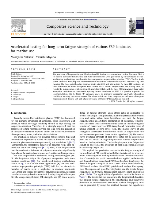
Accelerated testing for long-term fatigue strength of various FRP laminates for marine useMasayuki Nakada *,Yasushi MiyanoMaterials System Research Laboratory,Kanazawa Institute of Technology,3-1Yatsukaho,Hakusan,Ishikawa 924-0838,Japana r t i c l e i n f o Article history:Received 14September 2007Received in revised form 19February 2008Accepted 25February 2008Available online 8March 2008Keywords:A.Polymer–matrix compositesB.Durability B.FatigueD.Life predictiona b s t r a c tThe prediction of long-term fatigue life of various FRP laminates combined with resins,fibers and fabrics for marine use under temperature and water environments were performed by our developed acceler-ated testing methodology based on the time–temperature superposition principle (TTSP).The five kinds of FRP laminates were prepared under three water absorption conditions of Dry,Wet and Wet +Dry after molding.The three-point bending constant strain rate (CSR)and fatigue tests for these FRP laminates at three conditions of water absorption were carried out at various temperatures and loading rates.As results,the mater curves of fatigue strength as well as CSR strength for these FRP laminates at three water absorption conditions are constructed by using the test data based on TTSP.It is possible to predict the long-term fatigue life for these FRP laminates under an arbitrary temperature and water absorption conditions by using the master curves.The characteristics of time,temperature and water absorption dependencies of flexural CSR and fatigue strengths of these FRP laminates are clarified.Ó2008Elsevier Ltd.All rights reserved.1.IntroductionRecently carbon fiber reinforced plastics (CFRP)has been used for the primary structures of airplanes,ships,spacecrafts and others,in which the high reliability should be kept during the long-term operation.Therefore,it is strongly expected that the accelerated testing methodology for the long-term life prediction of composite structures exposed under the actual environments of temperature,water,and others is established.The mechanical behavior of polymer resins exhibits time and temperature dependence,called viscoelastic behavior,not only above the glass transition temperature T g but also below T g [1–7].Furthermore,the viscoelastic behavior of polymer resins also de-pends on the water absorption [8–11].Thus,it can be presumed that the mechanical behavior of polymer composites significantly depends on the water absorption as well as time and temperature.We have proposed the accelerated testing methodology to pre-dict the long-term fatigue life of polymer composites under tem-perature condition [12].Our accelerated testing methodology shown in Fig.1rests on the three hypotheses,(A)the time–tem-perature superposition principle (TTSP)held for the viscoelastic modulus of matrix resin is applicable to constant strain-rate (CSR),creep and fatigue strengths of polymer composites,(B)linear cumulative damage law for monotonic loading is applicable to pre-dict the creep strength from CSR strength,and (C)linear depen-dence of fatigue strength upon stress ratio is applicable to predict the fatigue strength under an arbitrary stress ratio between zero and unity.When these hypotheses are met,the fatigue strength under an arbitrary combination of frequency,tempera-ture,and stress ratio can be determined based on the following test results:(a)master curve of CSR strength and (b)master curve of fatigue strength at zero stress ratio.The master curve of CSR strength is constructed from the test results at single strain-rate and various temperatures based on the hypothesis (A).The master curve of fatigue strength at zero stress ratio can be constructed from the test results at single frequency for various temperatures based on the hypothesis (A).The loading frequency for fatigue test should be selected as the evolution of heat in specimen does not occur during fatigue test.We applied this prediction method to the fatigue strength of various kinds of FRP combined with fiber/matrix and its structure under various types of loading methods under temperature condi-tion.Concretely,the prediction method was applied to the tensile and flexural fatigue strengths of PAN-based carbon fiber/epoxy,the flexural fatigue strengths of PAN-based carbon fiber/vinylester,PAN-based carbon fiber/PEEK,pitch-based carbon fiber/epoxy,glass fiber/epoxy and glass fiber/vinylester,and the tensile fatigue strengths of GFRP/metal tapered joint,adhesive joint,and bolted joint [13–20].The applicability of prediction method is shown in Table 1.The tensile fatigue strength in the longitudinal direction,the flexural fatigue strengths in the longitudinal and transverse directions of unidirectional PAN-based carbon fiber/epoxy resin can be predicted by using this method,because the hypotheses0266-3538/$-see front matter Ó2008Elsevier Ltd.All rights reserved.doi:10.1016/pscitech.2008.02.030*Corresponding author.E-mail address:nakada@neptune.kanazawa-it.ac.jp (M.Nakada).Composites Science and Technology 69(2009)805–813Contents lists available at ScienceDirectComposites Science and Technologyj o ur na l h o me pa ge :w w w.e ls e v ie r.c o m/lo c a t e/c om p s c it e ch(A)–(C)are met.The flexural fatigue strengths of satin-woven PAN-based carbon fiber/epoxy resin,PAN-based carbon fiber/epoxy resin quasi-isotropic laminates,plain-woven PAN-based carbonfiber/vinylester resin and plain-woven glass fiber/vinylester resin can be also predicted.The flexural fatigue strengths of PAN-based carbon fiber/PEEK resin and pitch-based carbon fiber/epoxy resin can not be predicted,because the TTSP does not hold for the mechanical behavior of PEEK and the mechanical behavior of high modulus pitch-based carbon fibers itself shows time dependent behavior.For satin-woven glass fiber/epoxy resin,in the case of which the fracture of specimen is controlled by the delayed frac-ture of glass fiber,the hypothesis (A)does not met.The tensile fa-tigue strengths of FRP/metal tapered joint,adhesive joint,and bolted joint can be predicted by using thismethod.Fig.2.Constitution of five kinds of FRP laminates combined with different resins and fibers.Table 2Conditions for Dry,Wet,and Wet +Dry specimens Specimen In air In water In airDry As cured WetAs cured +95°C Â120h Wet +DryAs cured+95°C Â120h+150°C Â2hTable 1Applicability of proposed method to FRP and joint structures FiberMatrixTypeFiber/matrixLoading directionHypothesis (A)(B)(C)CarbonPANEpoxyUDT400/828LT T300/2500LB TB SW T400/3601LB QIL T800/3900-2B LB Vinylester PW T300/vinylester LB PEEKUD T300/PEEK LB ÂÂÂTB ÂÂÂPitchEpoxy UD XN40/25C LBÂÂGlassEpoxy SW E-glass/epoxyLB Â ÂVinylesterPWE-glass/vinylesterLT ÂLB ÂNotice:UD:unidirectional;SW:satin woven;PW:plain woven;QIL:quasi-isotropic laminates;LT:longitudinal tension;LB:longitudinal bending;TB:transverse bending FRP joint systemHypothesis (A)(B)(C)Conical shaped joint of GFRP/metal Brittle adhesive joint of GFRP/metal Ductile adhesive joint of GFRP/metal Bolted joint of GFRP/metal Bolted joint of CFRP/metalFig.1.Accelerated testing methodology for polymer composites.806M.Nakada,Y.Miyano /Composites Science and Technology 69(2009)805–813This paper is concerned with the prediction of long-term fatigue life offive kinds of FRP laminates for marine use under water absorption condition as well as temperature condition.These FRP laminates were prepared under three water absorption conditions of Dry,Wet and Wet+Dry after molding.The three-point bending CSR tests forfive kinds of FRP laminates at three conditions of water absorption were carried out at various temperatures and strain rates.Furthermore,the three-point bending fatigue tests at zero stress ratio for these specimens were carried out at various temperatures and frequencies.The characteristics of time,temper-ature,and water absorption dependencies offlexural fatigue strength as well asflexural CSR strength for these FRP laminates are discussed based on theTTSP.Fig.3.Water content versus soakingtime.Fig.4.Water content in resin and FRP for Wet and Wet+Dryconditions.Fig.5.Configuration of three-point bending test.Table3Test conditionsLoading type Deflection rate V(mm/min)Frequencyf(Hz)Stress ratio R(r min/r max)TemperatureT(°C)Creep forneat resin–––25–150CSR for FRP0.02*,2,200*––25–160Fatigue forFRP–0.02*,20.0525–140*Test conditions for confirming of applicability ofTTSP.Fig.6-1.Master curve of creep compliance for neat vinylester resin and shiftfactors.Fig.6-2.Master curve of creep compliance for neat epoxy resin and shift factors.M.Nakada,Y.Miyano/Composites Science and Technology69(2009)805–8138072.Experimental procedures2.1.Preparation of specimensThe base material offive kinds of FRP laminates employed in this study was plain fabric CFRP laminates T300carbonfibers/viny-lester(T300/VE).Thefirst selection of FRP laminate to T300/VE was the combinations of different fabrics,that isflat yarn plain fabric T700carbonfibers/vinylester(T700/VE-F)and multi-axial knitted T700carbonfibers/vinylester(T700/VE-K)for marine use and the second selection of FRP laminates to T300/VE was the combina-tions with differentfibers and matrix resin,that is plain fabric T300carbonfibers/epoxy(T300/EP)and plain fabric E-glass fibers/vinylester(E-glass/VE)shown in Fig.2.These FRP laminates were formed by resin transfer molding(RTM)except T300/EP which was formed by conventional hand lay up.The thickness of the laminates was approximately2mm.These FRP laminates were prepared under three water absorp-tion conditions of Dry,Wet and Wet+Dry after molding.Dry spec-imens by holding the cured specimens at150°C for2h in air,Wet specimens by soaking Dry specimens in hot water of95°C for 120h and Wet+Dry specimens by dehydrating the Wet specimens at150°C for2h in air were respectively prepared as shown on Ta-ble2.Fig.3shows water content versus soaking time at95°C and the soaking condition of95°C and120h was determined to Wet specimens.Fig.4shows water content in resin and FRP for Wet and Wet+Dry specimens.The water absorption of all FRP lami-nates increases with Wet condition of hot water of95°C for 120h.The water absorption of neat vinylester resin and its CFRP laminates returns to0%with Wet+Dry condition by re-drying and that of T300/EP and E-glass/VE does not return to0%.2.2.Experimental proceduresFig.5shows the configuration of three-point bending test and Table3shows the test conditions.To evaluate the viscoelastic behavior of vinylester(VE)and epoxy(EP)as matrix neat resin, the three-point bending creep tests for the neat vinylester and epoxy resins prepared at Dry,Wet and Wet+Dry conditions were carried out under various temperatures using an creep testingma-Fig.7.Master curves offlexural CSR strength at Dry,Wet and Wet+Dry conditions.808M.Nakada,Y.Miyano/Composites Science and Technology69(2009)805–813chine with temperature chamber.The creep compliance D c was calculated from the deflection d at the center of specimen using the following equation:D c¼4bh3dP0L3ð1Þwhere P0is the applied constant load(58.8N),L is the span (50mm),and b and h are the width(25mm)and the thickness (3.0mm)of specimen,respectively.The three-point bending CSR tests forfive kinds of FRP lami-nates at Dry,Wet and Wet+Dry conditions were carried out at various temperatures and strain rates.The span is L=80mm, and the width and thickness are b=15mm and h=2.0mm, respectively.The CSR tests were conducted at three loading-rates V=0.02,2,200mm/min and various constant temperatures T using an universal testing machine with temperature chamber. Theflexural CSR strength r s is calculated from the maximum load P s byr s¼3P s L2bh2:ð2ÞFurthermore,the three-point bending fatigue tests for thesespecimens were carried out at various constant temperatures Tand two loading frequencies f=2Hz and0.02Hz using an electro-hydraulic servo testing machine with temperature chamber.Thestress ratio R(=minimum stress/maximum stress)was0.05.Thelength,width,thickness of specimen,and span are the same tothose for theflexural CSR tests.Theflexural fatigue strength r f isdefined by maximum applied load P max for the number of cyclesto failure N f.r f¼3P max L2bh2:ð3ÞIn order to prevent the dryness of specimens at Wet conditionduring creep,CSR,and fatigue tests,the specimens were wrappedby a vinyl bag with including distilled water in the bag.3.Results and discussion3.1.Creep complianceThe left sides of upper graphs in Fig.6shows the creep compli-ance D c versus testing time t at various temperatures T for Dry,Wet Fig.8.Flexural CSR strength versus creep compliance of matrix resin at Dry,Wet and Wet+Dry conditions.M.Nakada,Y.Miyano/Composites Science and Technology69(2009)805–813809and Wet +Dry specimens of VE and EP resin.The master curves of D c versus the reduced time t 0were constructed by shifting D c at various constant temperatures along the log scale of t and the log scale of D c .Since the smooth master curve of D c for each specimen can be obtained as shown in the right sides of each graph,the time–temperature superposition principle (TTSP)is applicable for each D c .From these master curves,it is cleared that D c increases with water absorption and returns perfectly to that of Dry speci-men by re-drying after water absorption.The horizontal time–temperature shift factor a T 0(T )and the ver-tical temperature shift factor b T 0(T )at a reference temperature T 0plotted in lower graphs of Fig.6are,respectively,defined by log a T 0ðT Þ¼log t Àlog t 0ð4Þlog b T 0ðT Þ¼log D C ðt ;T ÞÀlog D C ðt 0;T 0Þð5Þ3.2.Flexural CSR strengthThe left side of each graph in Fig.7shows the flexural CSR strength r s versus time to failure t s at various temperatures T for Dry,Wet and Wet +Dry specimens of five kinds of FRP laminates,where t s is the time period from initial loading to maximum load during testing.The master curves of r s versus the reduced time to failure t 0s were constructed by shifting r s at various constant temperatures along the log scale of t s and the log scale of r s using the same time–temperature shift factors and a half of the temper-ature shift factors for D c of matrix resin shown in Fig.6.The reason why the shift amount to the log scale of r s is a half of that to the log scale of D c is mentioned after.Since the smooth master curve of r s for each specimen can be obtained as shown in the right side of each graph,the TTSP for D c of matrix resin is also applicable for the r s of corresponding FRP laminates.It is cleared from Fig.7that the r s for all five FRP laminates strongly decreases with increasing time and temperature and that these r s decreases with water absorption and returns to that of Dry specimens by re-drying after water absorption except that of GFRP laminates (E-glass/VE).The r s of Wet +Dry specimens of E-glass/VE does not return to that of Dry specimens.Fig.8shows the flexural CSR strength versus the creep com-pliance of matrix resin for the same conditions of time,temper-ature and water absorption for five FRP laminates.The degradation of flexural CSR strength for all CFRP laminates except GFRP laminates (E-glass/VE)is uniquely determined by the creep compliance of matrix resin.Therefore,the degradation rate of flexural CSR strength of these CFRP laminates is determined only by increasing of time,temperature and water absorption and is independent upon fiber constitutions which are the type,volume fraction and weaves.The slope is approximately 0.5shown in each graph of this figure.This indicates that the trigger of failure is the microbuckling of carbon fibers in the compression side of specimen shown by the following equation based on Dow’s the-ory [21]:Fig.9.Fracture appearances of specimens after flexural CSR test at 25°C at Dry condition.810M.Nakada,Y.Miyano /Composites Science and Technology 69(2009)805–813log r s ¼log K 0À12log D C ð6Þwhere r s is the CSR strength of CFRP laminates,K is the material con-stant and D c is the creep compliance of matrix resin.Actually,the frac-ture appearance indicates that the fracture mode for these CFRP laminates is the compressive fracture of warp carbon fibers in the compression side of specimen for all condition tested as shown in Fig.9.Therefore,this is the reason why the vertical shift amount for r s is a half of that for D c as mentioned above.The fracture mode for T300/EP laminates and E-glass/VE is the tensile fracture in the tension side of specimen at T =25°C.However the fracture mode at high tem-peratures is the compressive fracture in the compression side of spec-imen same to that for T300/VE laminates.3.3.Flexural fatigue strengthTo construct the master curve of flexural fatigue strength r f ,we need the reduced frequency f 0in addition to the reduced time to failure t 0f ,each defined by f 0¼f Áa T 0ðT Þ;t 0f ¼t f a T 0ðT Þ¼N ffð7Þwhere N f is the number of cycles to failure.The r f versus N f at frequency f =2Hz at various temperatureswere measured for Dry,Wet and Wet +Dry specimens of five kinds of FRP laminates.For examples,the r f versus N f curves at various temperatures for Dry specimen are shown in Fig.10.By converting f and N f into f 0and t 0f using Eq.(7),the time–tem-perature shift factors a T 0(T )and temperature shift factors b T 0(T )of the creep compliance of matrix resin for each specimen shown in Fig.6,the r f versus t 0f for each f 0were constructed for Dry,Wet and Wet +Dry specimens of five kinds of FRP laminates shown in Figs.11-1and 11-2.The curves consisted by solid cir-cles in these graphs show the master curves of CSR strengths which can be considered as the fatigue strength at stress ratio R =0and N f =1/2.Each curve consisted by hollow circles in these graphs shows the curve of fatigue strength r f versus re-duced time to failure t 0f at each reduced frequency f 0to diverge from the master curve of CSR strength.In order to confirm the applicability of TTSP for fatigue strength,we predicted the r f –N f curves at f =0.02Hz and com-pared them with the test results.The predicted r f from fatigue master curves for all FRP laminates agree well with experimental ones,therefore,the TTSP for the creep compliance of matrix re-sin also holds for fatigue strength of the corresponding FRPlaminates.Fig.10.r f versus N f curves at frequency 2Hz for Dry specimen.M.Nakada,Y.Miyano /Composites Science and Technology 69(2009)805–813811It is cleared from Figs.11-1and 11-2that the r f of all five FRP laminates strongly decreases with time to failure,temperature and water absorption and that the r f of four kinds of FRP laminates except GFRP laminates (E-glass/VE)decreases scarcely with N f although that of E-glass/VE decreases strongly with N f .And the degradation rate to time and temperature for the fatigue strength r f of these CFRP laminates is very similar to that for CSR strength.The r f of all FRP laminates also decreases with water absorption and that returns to that of Dry specimens by re-drying after water absorption except that of T300/EP in the range of long timeandFig.11-1.Master curves of flexural fatigue strength for T300/VE,T700/VE-F andT700/VE-K.Fig.11-2.Master curves of flexural fatigue strength for T300/VE,T300/EP and E-glass/VE.812M.Nakada,Y.Miyano /Composites Science and Technology 69(2009)805–813that of E-glass/VE in all range of time employed.The r f of Wet+ Dry specimens of T300/EP and E-glass/VE does not return to that of Dry specimens and shows irreversible behavior.4.ConclusionThe prediction of long-term fatigue life offive kinds of FRP lam-inates combined with matrix resin,fiber and fabric for marine use under temperature and water environments were performed by our developed accelerated testing methodology based on the time–temperature superposition principle(TTSP).The three-point bending CSR and fatigue tests forfive kinds of FRP laminates at three conditions of water absorption were carried out at various temperatures and loading rates.As results,theflexural fatigue strength of three kinds of CFRP laminates with vinylester resin as matrix strongly depends on water absorption as well as time and temperature,however scar-cely depends on the number of cycles to failure.The master curves of fatigue strength for these CFRP laminates are constructed by using the test data based on TTSP.The fatigue strength of these CFRP laminates decreases with water absorption and that returns to the initial fatigue strength by re-drying after water absorption. It is possible to predict the long-term fatigue life for these CFRP laminates under an arbitrary temperature and water absorption conditions by using the master curves.Furthermore,it is clear that the degradation rate of fatigue strength of these CFRP laminates is determined only by increasing of time,temperature and water absorption and is independent uponfiber constitutions which are the type,volume fraction and weaves.On the other hand,CFRP laminates with epoxy resin as matrix and GFRP laminates with vinylester resin as matrix chemically change by the process of water absorption and re-drying and the flexural fatigue strength of these FRP laminates decrease with this process.AcknowledgementsThe authors thank the Office of Naval Research for supporting this work through an ONR award(N000140110949)with Dr.Yapa Rajapakse as the program manager of solid mechanics.The authors thank Professor Richard Christensen at Stanford University as the consultant of this project and Toray Industries, Inc.as the supplier of CFRP laminates.All of experimental data were measured by the staffs and graduate students of author’s laboratory,Kanazawa Institute of Technology.The authors thank these staffs and graduate students,Dr.Naoyuki Sekine,Dr.Junji Noda,Ms.Jun Ichimura,Mr.Eiji Hayakawa and Mr.Takahito Uozu.References[1]Aboudi J,Cederbaum pos Struct1989;12:243–56.[2]Sullivan pos Sci Technol1990;39:207–32.[3]Gates T.Experimental Mechanics1992:68–73.[4]Miyano Y,Kanemitsu M,Kunio T,Kuhn H.J Compos Mater1986;20:520–38.[5]Miyano Y,McMurray MK,Enyama J,Nakada M.J Compos Mater1994;28:1250–60.[6]Miyano Y,McMurray MK,Kitade N,Nakada M,Mohri pos Mater1994;4:87–99.[7]Miyano Y,Nakada M,McMurray MK.J Compos Mater1995;29:1808–22.[8]Shen CH,Springer GS.J Compos Mater1976;10:2–20.[9]Kibler KG.In:AGRD conference proceedings;1980.p.8-1.[10]Neumann S,Marom G.Polym Compos1985;6:9–12.[11]Selzer R,Friedrich pos Part A1997;28A:595–604.[12]Miyano Y,Nakada M,McMurray MK,Muki R.J Compos Mater1997;31:619–38.[13]Miyano Y,Nakada M,Kudo H,Muki R.Prediction of tensile fatigue life undertemperature environment for unidirectional CFRP.Adv Compos Mater 1999;8:235–46.[14]Miyano Y,Nakada M,Muki R.Applicability of fatigue life prediction method topolymer composites.Mech Time-Dependent Mater1999;3:141–57.[15]Miyano Y,Nakada M,Muki R.Prediction of fatigue life of a conical shaped jointsystem forfiber reinforced plastics under arbitrary frequency,load ratio and temperature.Mech Time-Dependent Mater1997;1:143–59.[16]Sihn S,Miyano Y,Nakada M,Tsai SW.Time-and temperature-dependentfailures of a metal-to-composites bonded joint with PMMA adhesive material.J Compos Mater2003;37:35–54.[17]Sekine N,Nakada M,Miyano Y,Tsai SW.Time–temperature dependence oftensile fatigue strength for GFRP/metal and CFRP/metal bolted joints.In: Proceedings of13th international conference on composite materials,Beijing;June2001.p.1610.[18]Miyano Y,Nakada M,Sekine N.Accelerated testing for long-term durability ofGFRP laminates for marine pos Part B2004;35:497–502.[19]Miyano Y,Nakada M,Sekine N.Accelerated testing for long-term durability ofFRP laminates for marine use.J Compos Mater2005;39:5–20.[20]Miyano Y,Nakada M,Nishigaki K.Prediction of long-term fatigue life of quasi-isotropic CFRP laminates for aircraft use.Int J Fatigue2006;28:1217–25. [21]Dow NF,Gruntfest IJ.Space Sciences Laboratory,Structures and dynamicsoperation.T.I.S.R60SD389;1960.M.Nakada,Y.Miyano/Composites Science and Technology69(2009)805–813813。
材料概论生词
Self-contained 独立存在的atomic bonging 原子化学键crystalline ['kristəlain]基本翻译adj. 透明的;水晶般的;水晶制的defect ['di:fekt, di'f-, di'fekt]基本翻译n. 缺点,缺陷;不足之处vi. 变节;叛变网络释义defect:缺点,过失,投奔敌方,变节|晶格畸变|晶格结合力diffusion [di'fju:ʒən]基本翻译n. 扩散,传播;[物]漫射deformation [,di:fɔ:'meiʃən]基本翻译n. 变形Phase diagram网络释义phasediagram:精加工策略|相同图相转变图|相同图相转变图equilibrium [,i:kwi'libriəm]基本翻译n. 均衡;平静;保持平衡的能力empirical基本翻译adj. 经验主义的,完全根据经验的网络释义empirical:经验的|实验上的|实验的thermodynamics [,θə:məudai'næmiks, -di-]基本翻译n. 热力学网络释义Thermodynamics:热学|(热力学):研究热和能转化的科学.|物理专业热学irreversible thermodynamics:非平衡态热力学|不可逆过程热力学|不可逆热力学Statistic Thermodynamics:统计热力学complementary [,kɔmpli'mentəri]基本翻译adj. 补足的,补充的ceramic [si'ræmik]基本翻译n. 陶瓷;陶瓷制品adj. 陶瓷的;陶器的;制陶艺术的polymer ['pɔlimə]基本翻译n. [化]聚合物noncrystalline ['nɔn'kristəlain]基本翻译adj. 非结晶的composites [kəm'pəuzit]基本翻译n. 复合材料(composite的复数);复合体;菊科植物v. 使合成;使混合(composite的三单形式)fiberglass ['faibəɡlɑ:s]基本翻译n. 玻璃纤维;玻璃丝网络释义fiberglass:玻璃纤维|纤维玻璃|玻璃钢concrete [kən'kri:t, 'kɔnkri:t]基本翻译n. 具体物;凝结物adj. 混凝土的;实在的,具体的;有形的vt. 使凝固;用混凝土修筑vi. 凝结Mechanical property网络释义机械性能力学性能力学性质|机械性能力学性能力学性质Optical property网络释义opticalproperty:光学性能|光学性质|光性能光学性能insulator ['insjuleitə, 'insə-]基本翻译n. [电]绝缘体;从事绝缘工作的工人intermediate [,intə'mi:djət, -dieit]基本翻译n. 中间物;媒介adj. 中间的,中级的vi. 起媒介作用degradation [,deɡrə'deiʃən]基本翻译n. 退化;降格,降级;堕落网络释义degradation:退化|降解|降级Soil degradation:土壤退化environmental degradation:环境恶化|环境退化|环境质量下降parameter [pə'ræmitə]基本翻译n. 参数;系数;参量网络释义parameter:参数|参数,参量|参量parameter list:参数列表|变元表|参数表attendant [ə'tendənt]基本翻译n. 服务员,侍者;随员,陪从adj. 伴随的;侍候的presentation [,prezən'teiʃən, ,pri:-]基本翻译n. 描述,陈述;介绍;赠送structural ['strʌktʃərəl]基本翻译adj. 结构的;建筑的网络释义structural:结构|结构上的,组织上的|结构的Structural Engineer:结构/土建工程师|结构工程师|建筑工程师property ['prɔpəti]基本翻译n. 性质,性能;财产;所有权网络释义Property:属性|特性|物业,资产Property Management:物业管理|物业管理专员/助理|物业管理/商业中心magnetic property:磁性|磁性能|磁性(能)versatile ['və:sətail]基本翻译adj. 多才多艺的;通用的,万能的;多面手的deformability [di,fɔ:mə'biləti]基本翻译n. 可变形性ductility [dʌk'tiləti]基本翻译n. 延展性;柔软性;顺从网络释义ductility:延展性|延性的,韧性|韧性yield [ji:ld]基本翻译vi. 屈服,投降yield stress:屈服应力|屈服应力, 屈服点|降伏应力brittle ['britl]基本翻译adj. 易碎的,脆弱的;易生气的metallic luster基本翻译金属光泽;金属闪光料perspective [pə'spektiv]基本翻译n. 观点;远景;透视图adj. 透视的illustrate ['iləstreit]基本翻译vt. 阐明,举例说明;图解vi. 举例网络释义illustrate:举例说明|阐释|图解,插图1.1boxidized基本翻译adj. 被氧化的;生锈的v. 氧化;生锈(oxidize的过去分词)chemical degradation:化学降解;化学解;化学损坏(降解)refractory [ri'fræktəri]基本翻译n. 倔强的人;耐火物质adj. 难治的;难熔的;不听话的网络释义refractory:耐火材料|耐火的|不感受的furnace ['fə:nis]基本翻译n. 火炉,熔炉网络释义furnace:熔炉|炉子|反应堆crucible furnace:坩埚炉|坩锅炉|坩蜗炉fracture ['fræktʃə]基本翻译n. 破裂,断裂;骨折vt. 使破裂vi. 破裂;折断网络释义fracture:断裂|骨折|破裂fatigue fracture:疲劳断裂|疲劳断口|疲乏断裂Fracture toughness 断裂韧性silicate ['silikit, -keit]基本翻译n. 硅酸盐网络释义silicate:硅酸盐|硅盐酸|硅酸监calcium silicate:硅酸钙|矽酸钙|矽酸盐,调色素、收敛剂Claylike minerals 粘土状的矿物combination [,kɔmbi'neiʃən]基本翻译n. 结合;组合;联合;化合网络释义combination:组合|混合性皮肤|结合cutaway ['kʌtə,wei]基本翻译n. 常礼服;剖面图adj. 下摆裁成圆角的;剖面的网络释义Cutaway::剖视图incorporating [in'kɔ:pəreitiŋ]基本翻译adj. 合并的v. 合并(incorporate的ing形式)网络释义incorporating:合并|合并的,混合,组成公司carbide ['kɑ:baid]基本翻译n. 【化学】碳化物;碳化钙网络释义carbide:碳化物|炭化物|碳化合金constituent [kən'stitjuənt]基本翻译n. 成分;选民;委托人adj. 构成的;选举的网络释义constituent:成分|组成|构成constituent control:构成控件|子控件|组成控制项active constituent:活性成分|有功部分|有效成分ultraviolet [,ʌltrə'vaiələt]基本翻译n. 紫外线辐射,紫外光adj. 紫外的;紫外线的网络释义Ultraviolet:紫外线|电压不足|紫外线辐射ultraviolet radiation:紫外辐射|黑光|紫外线ultraviolet spectrophotometer:紫外分光光度计|紫外线光谱仪|紫外线分光光度计infrared [,infrə'red]基本翻译n. 红外线adj. 红外线的网络释义infrared:红外线|红外线的|红外Infrared Detectors:红外探测器|红外线检测器|其他红外线检测器infrared radiation:红外线|红外线辐射|又称为红外热辐射Chemical inertness 化学惰性devitrified基本翻译v. 脱玻(devitrify的过去式)网络释义devitrified:脱玻的|反玻璃化的(晶化的)devitrified glass:失透玻璃|闷光玻璃|微晶玻璃,失透玻璃thermal ['θə:məl]基本翻译n. 上升暖气流adj. 热的,热量的网络释义thermal:热的|热量的|耐温性thermal conductivity:导热性|导热率|热传导系数thermal slug:散热片crystallization [,kristəlai'zeiʃən]基本翻译n. 结晶化;具体化网络释义crystallization:结晶|晶化|结晶(作用)fractional crystallization:分步结晶|分离结晶|分级结晶oriented crystallization:取向结晶酌|定向结晶化|取向结晶动作Microscope-scale 显微级别porosity [pɔ:'rɔsiti, pəu-]基本翻译n. 有孔性,多孔性Lithium aluminosilicate 硅酸锂Low-thermal-expansion coefficient低膨胀系数Expansion coefficient网络释义expansioncoefficient:膨胀率膨胀系数|膨胀率膨胀系数low-expansioncoefficient:低膨胀系数formability [fɔ:mə'biliti]基本翻译n. 成形性,成型性能;可成形性网络释义formability:可成形性|成形性能|成型性能molecule ['mɔlikjul]基本翻译n. 分子;微小颗粒,微粒nonmetal ['nɔn,metəl, nɔn'metəl]基本翻译n. [化]非金属网络释义nonmetal:非金属|非金属元素|非金属的substantial [səb'stænʃəl]基本翻译n. 本质;重要材料adj. 大量的;实质的;内容充实的网络释义substantial:实质的|坚固的|大量的,重大的stiffness ['stifnis]基本翻译n. 僵硬;坚硬;不自然;顽固网络释义stiffness:抗挠性|刚度|硬挺度Polymer matrix聚合物机体component [kəm'pəunənt]基本翻译n. 成分;组件;元件adj. 组成的,构成的网络释义component:组件|成分|零件reactive component:无功分量|抗性分量|抗性分量,无功分量component force:分力|分力=>分力|释义:力的组成部分,分力百科component [kəm'pəunənt]基本翻译n. 成分;组件;元件adj. 组成的,构成的capable ['keipəbl]基本翻译adj. 能干的,能胜任的;有才华的网络释义capable:有能力的,有才能的|有能力的|有才干的,能干的Fiber-reinforced 纤维增强的aggregate ['æɡriɡət, 'æɡriɡeit]基本翻译n. 合计;集合体;总计adj. 聚合的;集合的;合计的vt. 集合;聚集;合计vi. 集合;聚集;合计Solid-state electronics 微电子学conversely ['kɔnvə:sli]基本翻译adv. 相反地insulator ['insjuleitə, 'insə-]基本翻译n. [电]绝缘体;从事绝缘工作的工人网络释义insulator:绝缘体|绝缘子|绝缘体,绝热体rectifier ['rektifaiə]基本翻译n. [电]整流器;改正者,矫正者网络释义rectifier:整流|整流器,检波器|精馏器laser ['leizə]基本翻译n. 激光网络释义laser:激光|莱塞(激光)|激光,激光器Cadmium sulfide网络释义cadmiumsulfide:硫化镉|硫化镉,镉黄impurity [im'pjuərəti]基本翻译n. 杂质;不纯;不洁underlying [,ʌndə'laiiŋ]基本翻译adj. 潜在的;根本的;在下面的;优先的v. 放在…的下面;为…的基础;优先于(underlie的ing形式)philosophy [fi'lɔsəfi, fə-]基本翻译n. 哲学;哲理;人生观array [ə'rei]基本翻译n. [计]数组,阵列;排列,列阵;大批,一系列;衣服vt. 排列,部署;打扮hexagonal [hek'sæɡənəl]基本翻译adj. 六边的,六角形的网络释义hexagonal:六角形的,六角的|六角形的|六边的hexagonal lattice:六方晶格|六角形栅格|六方点格hexagonal mesh:六方格|六边形网络|六角网deformation [,di:fɔ:'meiʃən]基本翻译n. 变形网络释义deformation:变形|形变|走样plastic deformation:塑性形变|塑性变形|金属塑性superimpose [,sju:pərim'pəuz]基本翻译vt. 添加;重叠;附加;安装opaque [əu'peik]基本翻译n. 不透明物adj. 不透明的;不传热的;迟钝的vt. 使不透明;使不反光residual [ri'zidjuəl, -dʒu-]基本翻译n. 剩余;残渣adj. 剩余的;残留的partical基本翻译n. 质点网络释义partical:粒子|质点|部分的partical order:偏序Partical Type:粒子类型prior ['praiə]基本翻译adj. 优先的;在先的,在前的adv. 在前,居先transparency [træns'pærənsi, -'pεə-,trænz-, trɑ:n-]基本翻译n. 透明,透明度;幻灯片;有图案的玻璃diffuse [di'fju:s]基本翻译adj. 弥漫的;散开的vt. 扩散;传播;漫射vi. 传播;四散densification [,densifi'keiʃən]基本翻译n. 密实化;封严;稠化vapor ['veipə]基本翻译n. 蒸汽;烟雾vt. 使……蒸发;使……汽化vi. 蒸发;吹牛;沮丧网络释义vapor:蒸汽|蒸气|水蒸气water vapor:水蒸汽|水汽|蒸汽saturated vapor:饱和蒸汽|饱和蒸气|饱和水蒸汽cylinder ['silində]基本翻译n. 圆筒;汽缸;柱面;圆柱状物网络释义cylinder:汽缸|圆柱体|铁桶cite [sait]基本翻译vt. 引用;传讯;想起;表彰demonstration [,demən'streiʃən]基本翻译n. 示范;证明;示威游行routine [ru:'ti:n]基本翻译n. 程序;日常工作;例行公事adj. 日常的;例行的anticipated [æn'tisipeit]基本翻译adj. 预期的;期望的v. 预料(anticipate的过去分词);盼望handling ['hændliŋ]基本翻译n. 处理adj. 操作的v. 负责;对待(handle的ing形式);触摸criterion [krai'tiəriən]基本翻译n. (批评判断的)标准;准则;规范;准据网络释义criterion:标准|准则|(衡量用的)标准fabricating基本翻译n. 制作;捏造;装配;二次加工adj. 制造的;装配的v. 制作;捏造(fabricate的ing形式);装配fraction ['frækʃən]基本翻译n. [数]分数;部分;小部分;稍微Periodic table 周期表dominate ['dɔmineit]基本翻译vt. 控制;支配;占优势;在中占主要地位vi. 占优势;处于支配地位junction ['dʒʌŋkʃən]基本翻译n. 连接,接合;交叉点;接合点vessel ['vesəl]基本翻译n. 船,舰;脉管,血管;容器,器皿网络释义Vessel:船舶|飞机|飞船aramid ['ærəmid]基本翻译n. 芳香族聚酰酩;人造纤维之一种spherical ['sferikəl, 'sfiə-]基本翻译adj. 球形的,球面的;天体的integral ['intiɡrəl]基本翻译n. [数学]积分;部分;完整adj. [数学]积分的;完整的,整体的blend [blend]基本翻译n. 混合;掺合物vt. 混合vi. 混合;协调optimum ['ɔptiməm]基本翻译adj. 最适宜的n. 最佳效果;最适宜条件retrieval [ri'tri:vəl]基本翻译n. 检索;取回;恢复;拯救glossary ['ɡlɔsəri]基本翻译n. 术语(特殊用语)表;词汇表;专业词典silicate ['silikit, -keit]基本翻译n. 硅酸盐dominant ['dɔminənt]基本翻译n. 显性adj. 显性的;占优势的;支配的,统治的Ferrous alloy 铁基合金Carbon steel 碳钢Cast iron 铸铁Precious metal 贵金属predominant [,pri'dɔminənt]基本翻译adj. 主要的;卓越的;支配的;有力的;有影响的Stress versus strain 应力应变Fracture toughness 断裂韧性fatigue [fə'ti:ɡ]基本翻译n. 疲劳,疲乏;杂役adj. 疲劳的vt. 使疲劳;使心智衰弱vi. 疲劳网络释义Bending fatigue:弯曲疲劳|弯曲疲惫|挠曲疲劳contact fatigue:接触疲劳|接触疲惫creep [kri:p]网络释义creep:蠕变|潜变|渐变creep strength:蠕变强度|潜变强度|蠕变弱度creep strain:蠕变变形|蠕动应变|蠕变应变kinetics [ki'netiks, kai-]基本翻译n. [物]动力学invariably [in'vɛəriəbli]基本翻译adv. 总是;不变地;一定地Corrosion resistance 抗腐蚀性能durable ['djuərəbl]基本翻译n. 耐用品adj. 耐用的,持久的eminently ['eminəntli]基本翻译adv. 突出地;显著地网络释义eminently:出众地,超凡的|突出地|著名地Ball bearing基本翻译n. 滚珠轴承Metal sheet 金属片Designation system 命名系统emerge [i'mə:dʒ]基本翻译vi. 浮现;摆脱;暴露网络释义emerge:出现|形成,显现|出定emerge verb:显现,暴露emerge":宜冒出"(出现,涌现,冒出)proprietary [prəu'praiətəri]基本翻译n. 所有权;所有人adj. 所有的;专利的;私人拥有的Hot rolling 热熔elevate ['eliveit]基本翻译vt. 提升;举起;振奋情绪等;提升…的职位Allow some stress relief 释放应力Stainless steel 不锈钢Turbine blades 涡轮叶片chromium ['krəumjəm]基本翻译n. [化]铬(24号元素,符号Cr)austenitic [,ɔsti'nitik]基本翻译adj. 奥氏体的网络释义austenitic:奥氏体的|奥氏体|沃斯田铁austenitic steel:沃斯田铁钢|奥氏体钢|奥式体钢austenitic transformation:奥氏体转变|奥氏体转变:Rapid-quench 快速淬火tetragonal [te'træɡənəl]基本翻译adj. 四角形的网络释义tetragonal:正方的|正方晶系的|四角形的martensite ['mɑ:tnzait]基本翻译n. [冶金]马氏体;[冶金]马登斯体;[冶金]马丁散铁网络释义martensite:马氏体/硬化铁炭|麻田散铁,麻田散体|马登斯体,马氏体Martensite Steel:马氏体钢|马登斯体钢|麻田散体钢Cutlery and spring 刀具和弹簧Precipitation hardening析出硬化|沉淀硬化multiphase ['mʌltifeiz]基本翻译n. 多相adj. 多相的;多方面的网络释义multiphase:多相|多相的|复相Dislocation motion 位错运动demanding [di'mɑ:ndiŋ]基本翻译adj. 苛求的;要求高的;吃力的tungsten ['tʌŋstən]基本翻译n. 钨(一种金属元素)molybdenum [mɔ'libdinəm]基本翻译n. [化]钼(金属元素,符号Mo,原子序号42)Dual role 双重作用cobalt [kəu'bɔ:lt]基本翻译n. 钴;钴类颜料;由钴制的深蓝色turbojet ['tə:bəudʒet]基本翻译n. 涡轮喷气飞机网络释义turbojet:涡轮喷气飞机|涡轮喷气发动机|喷射飞航turbojet engine:涡轮式喷气发动机|喷气涡轮机|涡轮喷射引擎Nonferrous alloy 非铁基合金kinetics [ki'netiks, kai-]基本翻译n. [物]动力学网络释义kinetics:动力学|动理学|动作学gas kinetics:气体运动学|气体动力(学理)论,气体分子运动论|气体运动论viscosity [vi'skɔsəti]基本翻译n. 粘性,粘度网络释义viscosity:涂料粘度|粘度|能量指示图kinematic viscosity:运动粘度|运动粘性|动粘度absolute viscosity:绝对粘度|绝对黏度|绝对黏度,动力黏度shrinkage ['ʃriŋkidʒ]基本翻译n. 收缩;减低inferior [in'fiəriə]基本翻译n. 下级;次品adj. 差的;自卑的;下级的,下等的网络释义inferior:低人一等的|下等的|下级的inferior goods:劣品|劣等商品|低等物品inferior to:级别低于,不如|比低级(次)|比...差,低于...的Wrought alloy网络释义wroughtalloy:可锻合金锻造合金less uniform 较不均一的Rolled and forged 滚压White iron网络释义whiteiron:白口铸铁|白口铸铁白铁Gray iron灰口铸铁|灰铸铁灰生铁|铸铁faceted ['fæsitid]基本翻译adj. 有小面的多面的cementite [si'mentait]基本翻译n. [冶]渗碳体,碳化铁网络释义cementite:渗碳体|渗碳体,碳化铁|碳化三铁体graphite ['ɡræfait]基本翻译n. 石墨;黑铅vt. 用石墨涂(或搀入等)flake [fleik]基本翻译n. 小薄片;火花vt. 使…成薄片;将…剥落vi. 剥落;成片状剥落spheroidal [sfiə'rɔidəl]基本翻译adj. 类似球体的,球状的Ductile iron 球墨铸铁Malleable iron展性铸铁可锻铸铁|韧性铁展性铸铁|韧性铁展性铸铁nodular ['nɔdjulə, -dʒə-]基本翻译adj. 结节状的;有结节的网络释义nodular:小节的|小结的|结核状的nodular iron:球[状石]墨铸铁|球〔状石〕墨铸铁|球墨铸铁precipitate [pri'sipitit, -teit]基本翻译n. 沉淀物adj. 突如其来的;猛地落下的;急促的vt. 使沉淀;促成;猛抛;使陷入vi. 沉淀;猛地落下;冷凝成为雨或雪等Rapidly solidified alloy 速凝合金Amorphous metal网络释义amorphousmetal:非晶体金属non-crystaline amorphousmetal:非晶合金eutectic [ju:'tektik]基本翻译n. 共熔合金adj. 共熔的;容易溶解的网络释义Eutectic:共晶|共晶体|低共熔混合物eutectic mixture:共晶混合物|低共熔(混合)物|共溶混合物eutectic peaction:共晶反应optimizing基本翻译n. 优化,最佳化adj. 最佳的mismatch [,mis'mætʃ]基本翻译n. 错配;不协调vt. 使配错solvent ['sɔlvənt, 'sɔ:l-]基本翻译n. 溶剂;解决方法adj. 有偿付能力的;有溶解力的solutesolute ['sɔlju:t, sɔ'lju:t, 'səulu:t]基本翻译n. 溶质;溶解物adj. 溶解的boron ['bɔ:rɔn]基本翻译n. [化]硼Grain boundary晶粒境界|晶界晶粒边界晶粒间界颗粒间界颗粒界限inhomogeneity [in,hɔməudʒe'ni:əti]基本翻译n. 不均一,多相;不同类;不同质;不同族by-product ['bai,prɔdʌkt]基本翻译n. 副产品;附带产生的结果;意外收获网络释义by-product:副产品|付产品|附带产生的结果novel ['nɔvəl]基本翻译n. 小说adj. 新奇的;异常的fine-grained ['fain-'ɡreind]基本翻译adj. 细粒的;有细密纹理的网络释义Fine-grained:细粒度|微粒的|高密度metastable [,metə'steibl]基本翻译adj. 亚稳的;相对稳定的网络释义metastable:亚稳态的|介稳态的|亚稳态的,介稳态的morphology [mɔ:'fɔlədʒi]基本翻译n. [生物]形态学,形态论;[语法]词法,词态学网络释义morphology:形态学|词法|形态crystal morphology:晶体形态学|形态结晶学|晶体结构,晶体组织correspondingly [,kɔris'pɔndiŋli]基本翻译adv. 相应地,相对地attribute [ə'tribju:t, 'ætribju:t]基本翻译n. 属性;特质vt. 归属;把…归于fabrication [fæbri'keiʃən]基本翻译n. 制造,建造;装配;伪造物taper off基本翻译逐渐变细;逐渐减少网络释义taper off:逐渐停止|逐渐变细|逐渐减弱Ore reserve 矿藏crust [krʌst]基本翻译n. 外壳;面包皮;坚硬外皮vt. 盖以硬皮;在上结硬皮vi. 结硬皮;结成外壳网络释义crust:地壳|外壳|外皮metallurgy [me'tælədʒi, 'metələ:dʒi]基本翻译n. 冶金;冶金学;冶金术temper ['tempə]基本翻译n. 脾气;(钢等)回火;性情;倾向vt. 使回火;锻炼;调和;使缓和vi. 回火;调和网络释义temper:回火|性情|脾气temper hardening:回火硬化extruded基本翻译adj. 压出的;受挤压的v. 使喷出;使伸出;驱逐(extrude的过去分词)titanium [tai'teiniəm, ti-]基本翻译n. [化]钛(金属元素)tenacious [ti'neiʃəs, tə-]基本翻译adj. 顽强的;坚韧的;固执的;紧握的;黏着力强的coating ['kəutiŋ]基本翻译n. 涂层;包衣;衣料v. 给…穿上外衣;盖上(coat的ing形式)passivation [pæsi'veiʃən]基本翻译n. 钝化;钝化处理网络释义passivation:钝化|钝化酌|钝化处理surface passivation:表面钝化|表面保护|表面钝化=>表面安定化vanadium [və'neidiəm]基本翻译n. [化]钒thermal ['θə:məl]基本翻译n. 上升暖气流adj. 热的,热量的网络释义thermal:热的|热量的|耐温性thermal conductivity:导热性|导热率|热传导系数coloration [,kʌlə'reiʃən]基本翻译n. 染色;着色beryllium [be'riliəm]基本翻译n. [化]铍(符号Be)tensile ['tensail, -səl]基本翻译adj. [物]拉力的;可伸长的;可拉长的Monel ['mɔnəl]基本翻译n. 蒙乃尔铜-镍合金Solution hardening溶液硬化固溶淬火固溶硬化inconel [,inkə'nel]基本翻译n. 因科内尔铬镍铁合金;铬镍铁合金网络释义inconel:铬镍铁合金|因科镣合金|因科内尔镍铬铁耐热耐蚀合金hastelloy ['heistə,lɔi]基本翻译n. 哈斯特洛伊耐蚀镍基合金网络释义Hastelloy:哈氏合金丝|哈斯特洛伊镍基耐蚀耐热合金|合金Die casting 钢模制造crucible ['kru:sibl]基本翻译n. 坩埚;严酷的考验galvanization [,ɡælvənai'zeiʃən, -ni'z-]基本翻译n. 镀锌,电镀;通流电网络释义galvanization:电镀|镀锌|直羚疗法grid [ɡrid]基本翻译n. [计]网格;格子,栅格;输电网网络释义grid:网格|格子,网格|格子antimony ['æntiməni]基本翻译n. 锑(符号Sb)toxicity [tɔk'sisəti]基本翻译n. 毒性niobium [nai'əubiəm]基本翻译n. [化]铌(41号元素,符号Nb)rhenium ['ri:niəm]基本翻译n. [化]铼(75号元素,符号为Re)tantalum ['tæntələm]基本翻译n. 钽(符号Ta,原子序73)tungsten ['tʌŋstən]基本翻译n. 钨(一种金属元素)iridium [ai'ridiəm, i'ri-]基本翻译n. [化]铱(Ir)osmium ['ɔzmiəm, 'ɔs-]基本翻译n. [化]锇palladium [pə'leidiəm]基本翻译n. [化]钯;守护神platinum ['plætinəm]基本翻译n. 铂;白金;唱片集达100万张的销售量;银灰色rhodium ['rəudiəm]基本翻译n. [化]铑(一种元素)ruthenium [ru:'θi:niəm]基本翻译n. [化]钌(化学元素,符号为Ru)catalytic [kætə'litik]基本翻译adj. 接触反应的;起催化作用的n. 催化剂;刺激因素demonstrate ['demənstreit]基本翻译vt. 证明;论证;展示vi. 示威exhaustive [iɡ'zɔ:stiv]基本翻译adj. 详尽的;彻底的;消耗的网络释义exhaustive:无遗漏的|详尽的,无遗漏的|会耗尽的tensile ['tensail, -səl]基本翻译adj. [物]拉力的;可伸长的;可拉长的网络释义tensile:拉力的,可拉伸的|可伸长的|拉的tensile stress:拉张应力|张应力|拉伸应力elongation [,i:lɔŋ'ɡeiʃən, i,lɔŋ-]基本翻译n. 伸长;伸长率;延伸率;延长网络释义elongation:延伸率|伸长度|伸长rate elongation:延长率specimen ['spesimin, -əmən]基本翻译n. 样品,样本;标本网络释义specimen:试样|标本|样品curve [kə:v]基本翻译n. 曲线;弯曲;曲线球;曲线图表adj. 弯曲的;曲线形的vt. 弯;使弯曲vi. 成曲形normalizing ['nɔ:məlaiziŋ]基本翻译n. 正火;正常化;规格化v. 使正常化;使正规化;对钢正火(normalize的ing形式)网络释义normalizing:正火|正常化|标准化geometry [dʒi'ɔmitri]基本翻译n. 几何学cross-sectional area网络释义cross-sectionalarea:横切面积|断面面积横截面积gage [ɡeidʒ]基本翻译n. 计量器;挑战;抵押品vt. 以为担保;以为赌注网络释义gage:量规|压力计|轨距Gage pressure:表压|表压力|计示压力thickness gage:测隙规,厚度规|厚度计|测厚计gage length 标距elastic deformation弹性变形弹性形变|弹性变形弹性形变plastic deformation:塑性变形柔性变形|塑性变形柔性变形specify ['spesəfai, -si-]基本翻译vt. 指定;详细说明;列举;把列入说明书网络释义specify:指定|指定说明|详细说明deviate ['di:vieit, 'di:viət]基本翻译vt. 使偏离vi. 脱离;越轨网络释义deviate:离题,逸出正轨|偏离|偏离、偏差yield strength网络释义yieldstrength:抗屈强度|降伏强度|港作拖船屈服强度intersection [,intə'sekʃən]基本翻译n. 交叉;十字路口;交集;交叉点网络释义intersection:交叉点,十字路口|交集|十字路口stretching of atomic bonds 原子键的伸长vicinity [vɪ'sɪnɪtɪ]基本翻译n. 邻近,附近;近处compressive [kəm'presiv]基本翻译adj. 压缩的;有压缩力的distortion and reformation of atomicbonds 扭曲与原子键的重新构建shear stress切变(应)力|剪应力切变应力切应力粘性摩擦应力modulus ['mɔdjuləs, -dʒu-]基本翻译n. 系数;模数网络释义modulus:系数|模数|绝对值modulus of elasticity弹性模数|弹性模量|弹性系数,弹性模数graphical ['ɡræfikəl]基本翻译adj. 图解的;绘画的;生动的manifest ['mænifest]基本翻译n. 载货单,货单;旅客名单adj. 显然的,明显的;明白的vt. 证明,表明;显示vi. 显示,出现springiness ['spriŋinis]基本翻译n. 有弹性;轻快网络释义springiness:弹性|(纸板)弹性|富于弹性ultimate tensile strength极限抗拉强度极限抗张强度|极限抗拉强度极限抗张强度phenomenon [fi'nɔminən, fə-]基本翻译n. 现象;奇迹;杰出的人才strain hardening应变硬化冷加工硬化变形硬化机械硬化cold working基本翻译冷加工,冷作网络释义cold working:冷加工|冷作工|冷加工,冷作cold-working:冷加工冷作|冷加工冷作steelbar cold-working:钢筋冷加工dimensions基本翻译n. 规模,大小neck down网络释义颈缩断开颈缩断开|颈缩断开颈缩断开percent elongation at failure伸长率crack [kræk]基本翻译n. 裂缝;声变;噼啪声adj. 最好的;高明的vt. 使破裂;打开;变声vi. 破裂;爆裂integrate ['intiɡreit, 'intiɡrit, -ɡreit]基本翻译n. 一体化;集成体adj. 整合的;完全的vt. 使…完整;使…成整体;求…的积分;表示…的总和vi. 求积分;取消隔离;成为一体routinely [ru:'ti:nli]基本翻译adv. 例行公事地;老一套地ripple ['ripl]基本翻译n. 波纹;涟漪;涟波vt. 在…上形成波痕vi. 起潺潺声onset ['ɔnset, 'ɔ:n-]基本翻译n. 开始,着手;发作;攻击,进攻Poisson's ratio 泊松比perpendicular [,pə:pən'dikjulə]基本翻译n. 垂线;垂直的位置adj. 垂直的,正交的;直立的;陡峭的网络释义perpendicular:垂直|垂直的|垂线indentation [,inden'teiʃən]基本翻译n. 压痕,刻痕;凹陷;缩排;呈锯齿状网络释义indentation:压痕|压入|缩排indentation test:压痕试验|凹痕硬度试验|球印硬度试验indentation ratio:压深率indenter [in'dentə]基本翻译n. [机械]硬度计压头网络释义indenter:压头|硬度计压头|刻痕器spherical indenter:球形压头diamond indenter:金刚石压头Brinell ['brinel]基本翻译n. 布氏硬度;布里涅耳(姓氏)网络释义BRINELL:采用布氏硬度|布里涅耳|布氏硬度Brinell microscope:布氏硬度测量显微镜Brinell tester:布氏硬度计vickers基本翻译n. 维氏硬度计knoop [nu:p]基本翻译n. 努普(硬度单位);努普显微压痕硬度试验仪网络释义Knoop:努普|努氏|努普(硬度单位)Knoop scale:努氏硬度标度|努氏标度knoop hardness:努氏硬度|努普硬度,努氏硬度|努普硬度.empirical基本翻译adj. 经验主义的,完全根据经验的网络释义empirical:经验的|实验上的|实验的correlate ['kɔ:rə,leit]基本翻译vi. 关联vt. 使有相互关系;互相有关系n. 相关物;相关联的人adj. 关联的网络释义correlating:关联dial ['daiəl, dail]基本翻译n. 转盘;刻度盘;钟面vt. 给拨号打电话vi. 拨号网络释义dial:刻度盘|拨号|号码盘analog ['ænəlɔɡ]基本翻译n. 模拟;类似物adj. 模拟的;有长短针的Charpy网络释义Charpy:夏比|冲击强度|简支梁Charpy specimen:却贝冲击试样|夏比冲击试样charpy test:恰贝试验|却贝试验|夏甫式冲辉验pendulum ['pendjuləm, -dʒə-]基本翻译n. 钟摆;摇锤;摇摆不定的事态网络释义Pendulum:荡。
工程英语测试题及答案

工程英语测试题及答案一、选择题(每题2分,共20分)1. What is the term used to describe the process of turning raw materials into finished products?A. FabricationB. AssemblyC. MachiningD. Casting答案:A2. The primary function of a ________ is to convert electrical energy into mechanical energy.A. MotorB. GeneratorC. TransformerD. Inverter答案:A3. In engineering, the term "stress" refers to:A. The internal resistance of a material to deformationB. The force applied to a materialC. The change in shape of a materialD. The rate of change of force答案:A4. Which of the following is not a type of welding process?A. Arc weldingB. Gas weldingC. Ultrasonic weldingD. Friction welding答案:C5. The process of designing and building a structure is known as:A. EngineeringB. ArchitectureC. ConstructionD. All of the above答案:D6. What does the abbreviation "CAD" stand for in the field of engineering?A. Computer-Aided DesignB. Computer-Aided DraftingC. Computer-Aided DevelopmentD. Computer-Aided Documentation答案:A7. The SI unit for pressure is:A. PascalB. NewtonC. JouleD. Watt答案:A8. A ________ is a type of joint that allows for relative movement between connected parts.A. Rigid jointB. Revolute jointC. Fixed jointD. Pin joint答案:B9. The process of removing material from an object to achieve the desired shape is known as:A. MachiningB. CastingC. ForgingD. Extrusion答案:A10. In engineering, the term "specification" refers to:A. A detailed description of the requirements of aprojectB. A list of materials to be used in a projectC. The estimated cost of a projectD. The timeline for a project答案:A二、填空题(每题1分,共10分)11. The ________ is the process of cutting a flat surface ona material.答案:sawing12. A ________ is a type of bearing that allows for rotation.答案:ball bearing13. The term "gearing" refers to the use of gears to transmit ________.答案:motion14. The ________ is the study of the properties of materials.答案:material science15. In a hydraulic system, a ________ is used to control the flow of fluid.答案:valve16. The ________ is the process of heating and cooling a material to alter its physical properties.答案:heat treatment17. The ________ is a tool used to measure the hardness of a material.答案:hardness tester18. A ________ is a type of joint that connects two parts ata fixed angle.答案: hinge joint19. The ________ is the process of joining two pieces ofmetal by heating them to a molten state.答案:fusion welding20. The ________ is the study of the behavior of structures under load.答案:structural analysis三、简答题(每题5分,共30分)21. Define the term "mechanical advantage" in engineering.答案:Mechanical advantage is the ratio of output force to input force in a simple machine, indicating how much the machine amplifies the force applied to it.22. Explain the concept of "factor of safety" in engineering design.答案:The factor of safety is a ratio used in engineering to ensure that a structure or component can withstand loads beyond the maximum expected in service, providing a margin of safety against failure.23. What is the purpose of a "stress-strain curve" in material testing?答案:A stress-strain curve is a graphical representation of the relationship between the stress applied to a material and the resulting strain, used to determine the material's mechanical properties such as elasticity, yield strength, and ultimate strength.24. Describe the difference between "static" and "dynamic" loads in engineering.答案:Static loads are constant forces that do not changeover time, while dynamic loads are forces that vary in magnitude or direction over time, often due to movement or vibrations.25. What is "creep" in the context of material behavior under load?答案:Creep。
Joints in Steel Construction-Composite Connections英文精品课件
1 998 The Steel Construction Institute
Apart from any fair dealing for the purposes of research or private study or criticism or review, as permitted under the Copyright Designs and Patents Act, 1 988, this publication may not be reproduced, stored or transmitted, in any form or by any means, without the prior permission in writing of the publishers, or in the case of reprographic reproduction only in accordance with the terms of the licences issued by the UK Copyright Licensing Agency, or in accordance with the terms of licences issued by the appropriate Reproduction Rights Organisation outside the UK.
Publications supplied to the Members of the Institute at a discount are not for resale by them.
Publication Number:
SCl-P-213
ISBN 185942 085 0
British Library Cataloguing-in-Publication Data. A catalogue record for this book is available from the British Library.
Bio-inspired hierarchical design of composite T-joints with improved structural properties
Bio-inspired hierarchical design of composite T-joints with improved structuralpropertiesL.Burns a ,b ,A.P.Mouritz a ,D.Pook b ,S.Feih a ,c ,⇑aSir Lawrence Wackett Aerospace Research Centre,School of Aerospace,Mechanical and Manufacturing Engineering,RMIT University,GPO Box 2476,Melbourne,Victoria 3001,Australia bBoeing Research and Technology Australia,226Lorimer St (Private Bag 4),Port Melbourne,Victoria 3207,Australia cSingapore Institute of Manufacturing Technology (SIMTech),Joining Technology Group,71Nanyang Drive,Singapore 638075,Singaporea r t i c l e i n f o Article history:Received 26March 2014Received in revised form 25September 2014Accepted 30September 2014Available online 7October 2014Keywords:B.StrengthB.Fracture toughnessC.Finite Element Analysis (FEA)E.Joints/joininga b s t r a c tThe biological principle of hierarchical (multi-scale level)design was used at the structural and laminate levels to design a novel carbon/epoxy T-joint with improved structural properties for potential use in light-weight aircraft structures.The bio-inspired structural modification mimics tree branch–trunk joints by embedding the stiffener flange into skin plies.This design concept results in increased fracture toughness due to crack branching and deflection.Simultaneously,bio-inspired ply angle optimisation was used to mimic the tailored arrangement of cellulose micro-fibrils observed in the wood cells contained within tree branch joints.The optimisation procedure minimises the interlaminar stress con-centration in the T-joint radius bend and increases strength while maintaining similar global laminate stiffness properties.The hierarchical joint resulted in a significantly improved tensile strength compared to a conventionally designed T-joint.The new design additionally exhibited higher absorbed strain energy to failure load for bending and tension loading.Additionally,the hierarchical T-joint had a significantly reduced critical joint cross-sectional area (weight)due to the embedded design.Ó2014Elsevier Ltd.All rights reserved.1.IntroductionT-shaped joints (‘‘T-joints’’)made of carbon fibre reinforced polymer composite are generally used in aircraft structures to join common details such as stiffeners to skin.Conventional composite T-joints consist of the skin,stiffener and flanges made of carbon/epoxy laminate,which are joined by adhesive bonding or co-curing (Fig.1).A long-standing problem with T-joints is delamination cracking between the skin and flange due to the low strength and toughness of the interfacial region between these two compo-nents and the presence of a large geometric stress concentration.Under externally applied load,damage often initiates within the radius bend laminate and delta-fillet region (Fig.1)where the internal interlaminar (peel)stresses are highest due to the geomet-ric stress concentration factor in this region.Cracks can initiate in the radius bend and delta-fillet regions and then propagate along the skin/flange interface which may severely weaken the joint.Various approaches have been used to increase the strength of T-joints,such as the use of toughened resins [1,2],redesigning the radius/delta-filet region to lower the geometric stress concen-tration factor [3,4],and inserting through-thickness reinforcement such as stitches or z-pins [5].An alternative approach is to mimic the design of structural joints found in nature which,in the case of trees,are made of orthotropic fibre reinforced composite material.Natural joints are required to meet specific criteria such as efficient use of mate-rial (light-weight),high failure strength and high fracture tough-ness to ensure survival.A defining feature of biological materials is hierarchical design,in which design features from the material to the structural length scales (spanning the nano-to macro-levels)work together in synergy to achieve weight-efficient structural properties [6–17].For example,tree branch–trunk joints have sev-eral important design features which provide high strength and toughness,even though some of the wood constituents (e.g.lignin and hemi-cellulose)are brittle [16,18,19].Research has focused on mimicking the nano-scale design of biological materials such as nacre from sea shells [20–25],laminate properties such as fibre placement [3,26]or the interface design of joints [4,27].However,to date there has been a lack of research embracing the hierarchical design principle of incorporat-ing bio-inspired features across multiple length scales spanning/10.1016/positesb.2014.09.0411359-8368/Ó2014Elsevier Ltd.All rights reserved.⇑Corresponding author at:Singapore Institute of Manufacturing Technology (SIMTech),Joining Technology Group,71Nanyang Drive,Singapore 638075,Singapore.Tel.:+6567938378;fax:+6567925362.E-mail address:feihs@.sg (S.Feih).both the laminate and structural properties offibre-reinforced composite materials for aerospace applications.Fig.2shows the macro-features of the tree branch–trunk joint which provide high mechanical performance.At the structural level,the branch is embedded into the trunk with a cone-shaped bond-line,which maximises the load transfer area compared to the butt-shaped connection used in composite T-joints[28].The cone-shaped structure also provides increased toughness by forc-ing interfacial cracks to grow in mode II(shear)rather than mode I(crack opening tension).This structural design feature therefore increases the load capacity and toughness of the tree joint[29]. At the material level,the packing density and orientation of micro-fibrils in the wood cell are tailored to the external loading conditions,such as self-weight and wind loads.The tailored design minimises local internal stress concentrations and can attain close to uniform strain conditions in the joint[7,29,30].to the tailoring of micro-fibril orientations in the wood cells com-prising tree joints to reduce localised stress concentrations.Burns and colleagues found that incorporating the selected design approaches separately led to improvement of one mechanical property at the expense of another.The joint toughness(strain energy to failure)was improved by partially embedding the carbon fibre–epoxy plies of the stiffenerflange into the skin laminate[28]. However,the disadvantage of the embedded design approach was a reduction to the damage initiation load and therefore design load by up to50%.This was due to an increase in the interlaminar ten-sile and shear stresses within the radius/delta-fillet region.A sep-arate optimisation of the ply pattern of the stiffener lay-up without embedded plies increased the failure initiation load of the compos-ite T-joint by about40%under an applied bending load;however the joint toughness was not improved[31].In this paper the authors present a novel composite T-joint design that merges these two important design features of tree branch joints.Wefirstly integrate the joint components at the structural level through embedded ply design and secondly opti-mise thefibre angles of the embedded ply lay-up at the laminate level.We demonstrate in this paper that these two design features work synergistically in a T-joint and result in improvements to both the strength and parative experimental test-ing of the hierarchical carbon/epoxy T-joint against a carbon/epoxy T-joint with a conventional design(no integration and quasi-iso-tropic laminate design)is performed under stiffener bending and tension loads to quantify improvements to the structural proper-ties.In addition,comparativefinite element analysis of the two joint designs is performed to assess the influence of the bio-inspired design features on the internal interlaminar stresses in the critical radius bend and delta-fillet region.These regions are1.Schematic of typical composite T-joint showing the definition of the criticaljoint area from which the weight of the joint is calculated.tomography(CT)images of the macro-structural design features of tree branch joints showing embedded design with50%integration(centre)front view;(right)side view(28).and(right)hierarchical T-joint design with embeddedflange plies integrated into50%of the skin and optimised ply anglesinner radius.Part B69(2015)222–231223is geometrically similar to the baseline joint,but incorporates novel design features at the structural and laminate levels which mimic tree branch joints.2.1.1.Structural level designIn the baseline joint theflange and skin are discrete structural components and are not integrated.These components are simply joined at the bond-line interface.This is the conventional design for composite T-joints used in aircraft structures,in which the skin and stiffener are separate components joined using adhesive bond-ing or co-curing(as illustrated in Fig.1)or fasteners.In compari-son,the unique structural design feature of the hierarchical joint is that some of theflange plies are integrated into the skin,rather than being completely separate.Theflange plies alternate between terminating in theflange taper and continuing on to form part of the skin.With this design,50%of theflange plies are integrated into the skin laminate,as illustrated in Fig.3.This design mimics the integration of structural components found in nature,such as tree branches embedded to the centre of the trunk,as shown in Fig.2[28].Although both the baseline and hierarchical designs fea-ture a32ply stiffener web and a16ply skin,the50%structural level integration of theflange plies into the skin in the hierarchical design results in a25%weight reduction in the critical joint area of the hierarchical T-joint compared to the baseline.The critical joint area for the T-joint design is defined by the cross-section created by the combined thickness of theflange and skin plies multiplied by the stiffener web thickness(Fig.1).minate level designIn the baseline joint the skin,stiffener andflange laminates each have a quasi-isotropic ply stacking pattern,which is the ply pattern used in most aircraft composite joints.The objective of the optimi-sation was to determine the ply sequence that reduced the peak peel stress in the radius bend region of the hierarchical joint under an externally applied bending moment[28,31,32–37].The objec-tive of the optimisation is not to simply copy the microfibril angles found in wood,but to apply the bio-inspired principle of tailoring fibre angles to the external loading conditions to attain mostly uniform strain conditions.It is postulated that uniform strain conditions maximise joint failure strength irrespective of the dif-ferences in the load cases of T-joints and tree branch–trunk joints. The skin laminate remains unchanged(quasi-isotropic).It is under-stood that the proposed design still shows significant differences to the wood joint.However,by allowing ply lay-up angles other than the typical quasi-isotropic stacking patterns,it is expected that interlaminar stresses in the radius region will be reduced and that consequently the failure initiation load(strength)of the hierarchical T-joint will be increased.Table1Skin and stiffener laminate design in baseline and hierarchical T-joints.Ply Skin laminate Stiffener laminate(mirrored)Baseline(°)Hierarchical(°)Baseline(°)Hierarchical(°)145h1(0)45h1(0)a20h3(70)0h2(36)3À45Àh4(À84)À45h3(70)a490Àh2(À36)90h4(84)590h5(12)90Àh4(À84)a6À45h7(50)À45Àh3(À70)70Àh8(À74)0Àh2(À36)a845Àh6(À50)45Àh1(0)9454545h5(12)a10000h6(50)Fig. 4.Geometry,coordinate systems and boundary conditions of composite T-joint.Table2Unidirectional carbon/epoxy composite properties used infinite element analysis.Material property Unidirectional prepreg(lavenderVTM264)Cured ply thickness0.2mm aIn-plane Young’s modulus E11117GPa aTransverse Young’s modulus E227.5GPa aInterlaminar Young’s modulusE337.5GPa bPoisson’s ratio m120.33aPoisson’s ratio m130.33bPoisson’s ratio m230.2bIn-plane shear modulus G12 4.1GPa aInterlaminar shear modulus G13 4.1GPa bInterlaminar shear modulus G23 2.3GPa aInterlaminar tensile strength Z t47.6MPa[38]Interlaminar shear strength S1384.3MPa[39]a Experimentally determined,b Assumption.Table3Effect size of each ply angle input variable in the hierarchical design optimisation.Optimisation plyangle variablePly number in stiffener radius bendlaminate stacking patternEffectsize h11,80.437(20%) h22,70.041(2%) h33,60.437(20%) h44,50.307(14%) h59,160.307(14%) h610,150.210(10%) h711,140.084(4%) h812,130.36(16%)224L.Burns et al./Composites:Part B69(2015)222–231The 32ply stiffener web laminate was designed according to the ply stacking sequence [h 1/h 2/h 3/h 4/Àh 4/Àh 3/Àh 2/Àh 1/h 5/h 6/h 7/h 8/Àh 8/Àh 7/Àh 6/Àh 5]s ,where the symbols h 1Àh 8represent the 8ply angle input variables in the optimisation.Ply 1and ply 16rep-resent respectively the outer and inner plies to the radius bend.This stacking sequence fulfills the design requirements for a bal-anced (matching ±off-axis plies)and symmetric ply stack around the mid-plane of the web laminate to prevent warping and bend-twist-shear mechanical coupling of the stiffener.The 16ply skin laminate remained quasi-isotropic for both designs and had a laminate stacking sequence of [45/0/À45/90/90/À45/0/45]s for both the baseline and hierarchical T-joints.Table 1gives the ply angles of the skin and stiffener laminates for the baseline and bio-inspired hierarchical T-joints,respectively.2.2.Finite element modelling of baseline and hierarchical T-joints FEA was performed using the software PATRAN v2012.1.2as the pre-processor and SIMULIA ABAQUS 6.9-2as the solver and post-processor.The geometry of the FE models for the two joints is shown in Fig.4.The joints were modelled ply-by-ply with one ele-ment in the through-thickness direction of each ply and two ele-ments in the width direction.Local coordinate systems were used for the skin,radius bends and stiffener web.The composite plies were constructed from HEX-20solid elements.Each ply was modelled with 30elements around the radius bend in the tangen-tial direction.The delta-fillet region of the base of the stiffener was constructed using HEX-20and TRI-15solid elements to model the unidirectional carbon/epoxy tape ‘noodle’,thus replicating the T-joint test specimens.The orthotropic element properties of the unidirectional carbon/epoxy prepreg used in the experimental T-joints are given in Table 2.The presence of residual cure stresses within the joints was not considered in the FE analysis.A linear perturbation analysis was conducted for the optimisation of the ply angles to minimise computational resources.Nonlinear geo-metric analyses were conducted for the comparison of the internal stress distributions of the two joint designs.The optimisation algorithm (multi-objective simulated anneal-ing)varied the fibre angle of each ply in the stiffener laminate from 0°to 90°in increments of 2°,and then calculated the resultant peak interlaminar tensile stress (r 33)under a perturbation bending moment within the tensile radius bend.The optimisation program was run with the single objective of minimising the peak interlam-inar tensile stress (r 33)within the tensile-side radius bend of the stiffener (refer to [31]for further details).A design constraint enforced that the global in-plane (A 11)and bending (D 11)stiffness values of the optimised stiffener laminate in the hierarchical T-joint were kept within ±10%of the baseline quasi-isotropic stiffener laminate.This constraint ensured that the stiffness properties of the stiffener laminate were not reduced in the attempt to improve other properties such as strength and toughness.The A 11value of the baseline quasi-isotropic stiffener laminate was 318GPa mm,and therefore the in-plane stiffness (A 11)value for the hierarchical stiffener laminate was confined to within the range of 286–350GPa mm (i.e.±10%).Similarly,the bending stiffness (D 11)value of the baseline quasi-isotropicstiffener laminate was 1100GPa mm 3,and the hierarchical stiff-ener laminate was constrained to values between 990and 1210GPa mm 3.The initial design was an arbitrary design that fulfilled the glo-bal stiffness constraints and was set to [20/40/50/60/À60/À50/À40/À20/24/34/44/54/À54/À44/À34/À24]s .The optimised ply pattern for the stiffener laminate was calculated to be [0/36/70/84/À84/À70/À36/0/12/50/50/74/À74/À50/À50/À12]s .Table 3summarises the effect size of each ply angle in the hierarchical design optimisation of the stiffener laminate.The effect size quan-tifies the strength of the relationship between the input variables (stiffener laminate ply angles)and the output variable (peak inter-laminar tensile stress in the radius bend).A larger effect size indi-cates that there is a stronger relationship between the input and output variables.Table 3shows that variables h 1and h 3(represent-ing the ply angles of plies 1,3,6and 8)have the strongest influence on the peak interlaminar tensile stress in the radius bend.On theTable 4Optimisation results for the hierarchical T-joint compared to the baseline T-joint.(Percentages in brackets are based on comparison to the baseline T-joint).Baseline T-jointBio-inspired T-jointT-joint stiffener laminate stacking pattern [45/0/À45/90/90/À45/0/45]2s [0/36/70/84/À84/À70/À36/0/12/50/50/74/À74/À50/À50/À12]s In-plane stiffness A 11a (GPa mm)317.8306.0(À3.7%)Bending stiffness D 11a (GPa mm 3)10991096(À0.3%)aLaminatetheory.L.Burns et al./Composites:Part B 69(2015)222–231225other hand,the optimisation was least sensitive to ply angles h2 and h7(representing the angles of plies2,7,11and14).The orien-tation of these plies could therefore be adjusted to attain the desired global stiffness properties of the stiffener laminate without significantly altering the peak interlaminar tensile stress.The results of the optimisation program are provided in Table4.Non-linear FE analysis of the T-joints was performed to deter-mine changes to the internal stresses caused by hierarchical design modifications at the structural and laminate levels.FEA was con-ducted to determine the interlaminar tensile and shear stress dis-tributions in the radius bend/delta-fillet region at the average damage initiation load of the baseline T-joint as determined from experimental tests.Non-linear analysis also gave information about the ply failure location and the failure mode,e.g.interlami-nar tensile-dominated,interlaminar shear-dominated or mixed-mode.The boundary conditions for the non-linear analyses are shown in Fig.4.In the bending load case,the average damage ini-tiation displacement was applied perpendicular to the stiffener web at a distance of103mm from theflange via a rigid link,repli-cating the steel clamps in the test rig.The test rig did not allow for rotation of the stiffener web.Under large bending displacements as experienced towards the end of the bend tests,the test rig there-fore induced a secondary tensile load on the stiffener web.In the FE analysis the displacement of the stiffener web in the global y-by Lavender;T700fibres and HS200epoxy)and were cured in the autoclave at120°C and620kPa for two hours as per the manufac-turer’s instructions.The skin and stiffener were bonded by co-cur-ing withoutfilm adhesive.The skin for both the baseline and hierarchical T-joints was a quasi-isotropic laminate consisting of 16carbon/epoxy plies laid up in the quasi-isotropic stacking sequence of[45/0/À45/90/90/À45/0/45]s.The stiffener to the base-line T-joint consisted of a32-ply laminate that also had a quasi-isotropic ply stacking pattern of[45/0/À45/90/90/À45/0/45]2s.In contrast,the optimised ply stacking pattern of the hierarchical T-joint stiffener was[0/36/70/84/À84/À70/À36/0/12/50/50/74/À74/À50/À50/À12]s.2.4.Structural testing of T-jointsThe baseline and hierarchical joints were tested under both bending and tensile loading using a50kN Instron test machine (Model5569)to determine their strength and toughness,as shown schematically in Fig.4.The skin was clamped on either side of a 150mm working section containing the stiffener web andflange. The bending test involved applying a load perpendicular to the stiffener web via a clamp attached to the Instron machine.Load was applied at a constant displacement rate of3mm/min to a maximum displacement of25mm,at which point the test was stopped.The tensile test involved exerting a pull-off force onto the stiffener web while the skin was restrained by clamping.The pull-off force was applied at a displacement rate of1mm/min to a maximum displacement of7mm.Six samples of both types of joint were tested in bending and tension to determine the standard variation in the measured prop-erty values.High-speed photography at an image capture rate of 5000frames per second was used to observe the initiation and propagation of damage in the T-joints during testing.3.Results and discussion3.1.T-joints under stiffener bending loadTable5Comparison between the structural properties of the baseline and hierarchical T-joints under bending loading[±standard deviation based on6samples].Properties are normalised with respect to the critical joint area ratio.Baseline T-joint HierarchicalT-jointD(%)Critical joint area(mm2)42[±1.8]30[±0.4]À29Damage initiation load(N)268[±9.1]281[±24]5Normalised damage initiationload(N)268[±9.1]397[±33]48Strain energy to failure(J)2420[±1299]3613[±534]49Normalised strain energy tofailure(J)2420[±1299]5109[±756]111damage initiation and failure modes under bending:(left)delamination damage initiation load;(centre)failure load drop;Arrow indicates direction of bending moment.226L.Burns et al./Composites:Part B69(2015)222–231the following,the measured bending load (P )hierarchical joint will be normalised with respect to the ratio critical cross-sectional joint area of the baseline joint (A hierarchical joint (A hierarchical )via P norm =P ⁄(A baseline /A The critical joint area was defined previously as the calculated by the stiffener web thickness multiplied by the flange/skin thickness.When the applied bending force normalised,the stiffness properties of the two ilar as shown in Fig.5b.This reflects the global optimisation constraints of similar bending stiffness The following structural properties of the from the bending tests were significant to the (i)damage initiation load (strength),defined load drop;and (ii)strain energy to failure (toughness),the area under the curve up to ultimate load.measured for the baseline and hierarchical joints in Table 5.The damage initiation load for both and within the standard error of the experimental work by the authors [28]showed that 50%damage initiation and failure modes under bending:(left)delamination damage initiation load;(centre)failure load drop;Arrow indicates direction of bending moment.Micro-CT cross-section of branch–trunk joint showing fibre bridging,branching and deflection.FEA interlaminar tensile stress (r 33)distribution under bending load at the average damage initiation load of the baseline T-joint of 268N:(left)baseline;hierarchical T-joint.Table 6Summary of the FEA peak interlaminar tensile and shear stresses the baseline and hierarchical joints at a bending load of Baseline T-jointstiffener plies into the skin without optimisation of the ply stacking pattern reduces the damage initiation load of the T-joint in both the tensile and bending load cases by about 35%compared to the baseline joint.In contrast,the damage initiation load of the hierarchical T-joint is slightly higher than the baseline and the normalised damage initiation load is 48%higher compared to the baseline,reflecting the success of the stiffener laminate optimisa-tion in delaying delamination damage initiation.The damage mode for both the baseline and hierarchical T-joints was the same.Delamination damage initiated within the radius bend region where interlaminar stresses are highest under the bending load applied to the stiffener.High-speed photography of the baseline (Fig.6)and hierarchical (Fig.7)joint specimensduring bend testing revealed that damage initiated as a delamina-tion crack in the tensile loaded radius bend.This region was strained in tension under the applied stiffener bending moment.Delamination damage initiated at the interface between plies hav-ing the highest bending stiffness,and consequently the location of the initial delamination damage was different for the baseline and hierarchical joints due to their different ply stacking patterns.Damage to the baseline joint initiated between ply 2(0°)and ply 3(À45°)(Fig.6).Further cracks then grew along the skin-flange interface as failure progressed under increasing bending displace-ment.In the hierarchical joint,delamination first occurred between ply 7(À36°)and ply 8(0°)(Fig.7).Following initial fail-ure,multiple cracks then developed within the radius bend region of the hierarchical joint.Final failure showed partial stabilization of the skin/flange bond-line crack through bridging and deflection as a result of embedded ply design.Burns et al.[28]have shown that tree branch joints also gain significant toughness by multiple cracking and crack branching,as shown in Fig.8.Fibre bridging,crack branching and deflection are fracture toughening processes in composites (as they are in tree joints),and this accounts for the hierarchical joint having improved load capacity and strain energy absorption following first failure.Table 5shows that both the original (49%)and normalised strain energy to failure (111%)are significantly higher in the hier-archical joint compared to the baseline joint.This is the result of the higher load carrying capacity of the hierarchical design follow-ing damage initiation.The increased toughness of the bio-inspired T-joint is mostly due to the increased displacement at ultimate (maximum)load.This behaviour is similar to tree branch joints,which exhibit high toughness and failure strain despite the constit-uents being brittle [28].FEA was used to further investigate the initiation of damage in the baseline and hierarchical joints under bending.The magnitude and distribution of internal interlaminar tensile and shear stresses in the radius bend and delta-fillet regions of the T-joints were determined.The stresses in this region were analysed at the aver-age experimentally measured damage initiation load for the base-line T-joint (268N).FE analysis revealed that the interlaminar tensile stress is concentrated at about the mid-point both tangen-tially and radially across the radius bend of both joints,as shown in Fig.9.A completely uniform interlaminar tensile stress distribution without any localised regions of concentrated stress was not attained in the hierarchical joint (as it is in tree joints).However,a significant reduction in the peak interlaminar tensile stress was achieved by altering the internal laminate stiffness properties via the stiffener ply stacking pattern.In the hierarchical T-joint the largest difference in ply angle between adjacent plies is 38°(reduced from 45°in the baseline joint),which occurs between ply 9(12°)and ply 10(50°).This reduction of ply angle mismatch between adjacent plies across the radius bend eases the transition of the internal laminate stiffness properties and results in a more even distribution of interlaminar stresses in the radius bend region of the hierarchical T-joint.This partially mimics the fibril pattern of tree branch joints which attain near iso-strain conditions due to optimised packing density and alignment of the cellulose fibres.A summary of the FEA results for the two joint types under the bending load is given in Table 6.The peak interlaminar tensile and shear stresses in the hierarchical joint at the average experimental damage initiation load of the baseline joint were lower than the stresses in the baseline joint by 15%and 7%,respectively.The decrease in these critical stress components for the hierarchical joint is reflected in the experimentally observed increased load for failure initiation.The average interlaminar tensile and shear strengths for the carbon–epoxy composite material used in the T-jointsareTable 7Comparison between the structural properties of the baseline and hierarchical joints under tension loading [±standard deviation based on 6samples].Properties are normalised with respect to the critical joint area ratio.Baseline T-jointHierarchical T-joint D (%)Critical joint area (mm 2)41.6[±0.9]30[±0.5]À28Damage initiation load (N)876[±33]1115[±168]27Normalised damage initiation load (N)876[±33]1550[±234]77Strain energy to failure (J)1881[±396]2936[±1542]56Normalised strain energy to failure (J)1881[±396]4083[±2145]117228L.Burns et al./Composites:Part B 69(2015)222–231。
国家科研论文和科技信息高端交流平台的战略定位与核心特征
国家科研论文和科技信息高端交流平台的战略定位与核心特征*李广建,罗立群*本文系国家社会科学基金重大项目“大数据时代知识融合的体系架构、实现模式及实证研究”(项目编号:15ZDB129)研究成果。
摘要建设高端交流平台是对国家科技信息和科技情报体系的顶层设计,也是新时期科技情报研究和工作的指导思想,为科技情报的未来指明了发展方向。
在国家“十四五”规划中,高端交流平台的构建上升到了国家战略高度,是加强我国科学战略力量的重要任务之一,相较于一般意义的平台具有更丰富的内涵和更高的定位。
文章站在全球科技格局和创新生态的高度,从国家科技安全、国家重大需求、科技创新范式等三个维度系统思考高端交流平台的战略定位。
基于对高端交流平台的三个定位、中国国家科技战略发展的根本需要以及对全球科技创新态势的正确认知,结合中国国情,从三个维度阐释高端交流平台构建的核心特征:一是开放,从单向被动不对等开放走向双向主动对等开放交流;二是融合,从成果发布走向知识融合;三是计算,从辅助科学发现的工具走向自主科学发现的主体。
关键词高端交流平台知识融合情报计算科学发现开放科学引用本文格式李广建,罗立群.国家科研论文和科技信息高端交流平台的战略定位与核心特征[J].图书馆论坛,2022,42(1):13-20.On the Positioning and Core Features of the National High-end Exchange Platform for Scientific and Technological Papers and InformationLI Guangjian &LUO LiqunAbstract The construction of the national high-end exchange platform for scientific and technological papers and information is among the top-level designs of the national scientific and technological information and intelligence system ,and it is vital for the strengthening of China ’s scientific strategic forces.With a view of global scientific andtechnological pattern and innovation ecology ,this paper discusses the positioning of such a national high-end exchange platform ,focusing on national scientific and technological security ,major national needs ,and scientific and technological innovation paradigms.It then makes an analysis of its three core features ,i.e.,openness ,fusion ,and computing.As for openness ,it should transfer from the one-way passive non-equivalent openness to the two-way active reciprocal open communication.As for fusion ,it should transfer from the singlerelease of scientific and technological findings to the fusion of such findings.As for computing ,it should not onlyact as a tool to assist scientific discovery ,but also become a main body of autonomous independent scientific discoveries.Keywords high-end exchange platform ;knowledge fusion ;intelligence computing ;scientific discovery ;open science0引言国家科研论文和科技信息高端交流平台(以下简称“高端交流平台”)已经被正式列入《中华人民共和国国民经济和社会发展第十四个五年规划和2035年远景目标纲要》,这是党和国家在“百年未有之大变局”时代对我国国家科技创新体系的高瞻远瞩,是对国家科技信息和科技情报体系的顶层设计,也是新时期科技情报研究和工作的指导思想,为科技情报的未来指明了发展方向。
材料科学与工程专业英语课件
1.1.1 Iron and Steel
The iron ore which we find on earth is not pure. It contains some impurities that must be removed by smelting. The process of smelting consists of heating the ore in a blast furnace with coke and limestone, and reducing it to metal. Blasts of hot air enter the furnace from the bottom and provide the oxygen that is necessary for the reduction of the ore.
1.1.1 Iron and Steel
• We can melt this down again in another furnace-a cupola-with more coke and limestone, and tap it out into a ladle or directly into molds. This is cast iron. Cast iron does not have the strength of steel. It is brittle and may fracture under tension.
Engineered cementitious composites for
Engineered cementitious composites for effectiveFRP-strengthening of RC beamsM.Maalej *,K.S.LeongDepartment of Civil Engineering,National University of Singapore,1Engineering Drive 2,Singapore 117576,SingaporeReceived 8March 2004;received in revised form 3November 2004;accepted 24November 2004Available online 19January 2005AbstractThis paper presents the results of an experimental program designed to evaluate the performance of FRP-strengthened RC beams incorporating engineered cementitious composites (ECC)as a ductile layer around the main flexural reinforcement (ECC layered beams).The load-carrying and deflection capacities as well as the maximum FRP strain at failure are used as criteria to evaluate the performance.Further,2-D numerical simulation is performed to verify the experimental results.The results have shown that ECC can indeed be used to delay debonding of the FRP resulting in effective use of the FRP material.These positive results warrant further studies on the use of ECC in combination with FRP to repair and strengthen deteriorating RC structures,particularly those where deteriorated concrete has to be replaced with a new repair material.Ó2005Elsevier Ltd.All rights reserved.Keywords:A.Carbon fibres;A.Short-fibre composites;B.Debonding;B.Interface;C.Stress concentration1.IntroductionThe applications of fibre reinforced polymer (FRP)composites to concrete structures have been studied intensively over the past few years in view of the many advantages that FRPs possess [1,2].While FRP has been shown to be effective in strengthening RC beams,strength increases have generally been associated with reductions in the beam deflection capacity due to prema-ture debonding [3,4].Debonding failure modes occur mainly due to interfacial shear and normal stress con-centrations at FRP-cut offpoints and at flexural cracks along the RC beam.In the present study,it is suggested that if the quasi-brittle concrete material which surrounds the main flex-ural reinforcement is replaced with a ductile engineered cementitious composite (ECC),then it would be possibleto delay the debonding failure mode and hence increase the deflection capacity of the strengthened beam.ECC is a cement-based material designed to exhibit tensile strain-hardening by adding to the cement-based matrix a specific amount of short randomly distributed fibres of proper type and property [5].ECCs are characterized by their high tensile strain capacity,fracture energy and notch insensitivity [6].Under uniaxial tension,sequen-tially developed parallel cracks contribute to the inelas-tic strain at increasing stress level.The ultimate tensile strength and strain capacity can be as high as 5MPa and 4%,respectively.The latter is two orders of magni-tude higher than that of normal or ordinary fibre rein-forced concrete.When ECC is introduced in a RC member,more but thinner cracks are expected to form on the beam tensile face rather than fewer but wider cracks in the case of an ordinary concrete beam [7].More frequent but finer cracks are expected to reduce crack-induced stress con-centration and result in a more efficient stress distribu-0266-3538/$-see front matter Ó2005Elsevier Ltd.All rights reserved.doi:10.1016/pscitech.2004.11.007*Corresponding author.Tel.:+6568744913;fax:+6567791635.E-mail address:cvemm@.sg (M.Maalej).Composites Science and Technology 65(2005)1120–1128/locate/compscitechCOMPOSITES SCIENCE AND TECHNOLOGYtion in the FRP layer.The objective of the present paper is therefore to establish both experimentally and numer-ically the structural performance of FRP-strengthened RC beams incorporating a ductile ECC layer around the mainflexural reinforcement.The load-carrying and deflection capacities as well as the maximum FRP strain at failure are used as criteria to evaluate the performance.2.Experimental investigation2.1.Experimental programTwo series of RC beams were included in the experi-mental program.One series consisted of two ordinary RC beams(beam A1and A2)and another series con-sisted of two ECC layered beams(ECC-1and ECC-2). In each series,one specimen was strengthened using externally bonded CFRP while the second was kept as a control in order to compare its load–deflection behav-iour under third-point loading with the strengthened specimen.For all beams,the longitudinal reinforce-ments consisted of3–10mm diameter deformed bars in the tension zone and2–10mm diameter deformed bars in the compression zone,corresponding to rein-forcement ratios of1.71%tensile and1.14%compres-sive.Shear reinforcement consisted of6mm plane bar stirrups spaced at60mm c/c in the shear span and a clear cover of15mm was used throughout.The ECC layer was about one third of the total depth of the beam as shown in Fig.1and only one layer of CFRP sheet was used to strengthen the beam.The spec-imen dimensions and reinforcement details of the ECC layered beams were similar to those of the ordinary RC beams(A1and A2),except that for beam ECC-2,the distance between the support and the CFRP cut-offpoint was increased from25to100mm to intention-ally increase the peeling stresses in the region around the CFRP cut-offpoint.The ECC material used in this investigation was rein-forced with both high modulus(steel)and relatively low modulus(polyethylene)fibres with respective volume fractions of0.5%and1.5%.The properties of bothfibres are given in Table1.In addition,Type I portland cement,silica fume and superplasticizer were used to form the cement paste matrix.Further details on the mix constituents of the ECC and the concrete are given in Table2.The material properties for the CFRP and those for the ECC and concrete at28days are shown in Tables3and4,respectively.Tensile stress–strain curves obtained from ECC coupon specimens measuring 300·75·15mm are shown in Fig.2.Further details regarding the ECC material and its properties can be found in Maalej et al.[8].To measure the tensile strain distribution in the CFRP,the CFRP sheet in each strengthened beamNotationc cohesiond effective beam depthDR deflection ratioE a elastic modulus of adhesiveE c elastic modulus of concreteE elastic elastic energy(area under the linear-elasticpotion of the load–deflection curve)E p elastic modulus of CFRP sheetE s elastic modulus of steelE tot total energy up to ultimate load(area underthe load–deflection curve)f0 c compressive strength of concrete/ECCf ct tensile strength of concrete/ECCf t p CFRP sheet tensile rupture strengthf y yield stress of tension steel reinforcement G a shear modulus of adhesive P u beam ultimate loadSR strengthening ratiot a thickness of the adhesive layert p thickness of one layer of CFRP sheetD u midspan beam deflection at ultimateloadD y midspan deflection at yielding of tension steelreinforcementb shear retentione ct concrete peak tensile strain(=f ct/E c)e tpCFRP sheet tensile rupture straine s maximum tensile strain at which concretetensile stress is equal to zero/friction anglel e energy ductility indexl D deflection ductility indexw dilatation angleM.Maalej,K.S.Leong/Composites Science and Technology65(2005)1120–11281121was instrumented with 27electrical strain gauges distrib-uted along the length of the beam.The detail positions of the strain gauges are shown in Table 5.A total of 10strain gauges spaced at 20mm were placed near the cut-offpoint to measure the steep variation of strain (see Fig.3).2.2.Test resultsThe load–deflection curves of the control as well as the CFRP-strengthened ECC beams (beams ECC-1and ECC-2,respectively)are presented in Fig.4together with the load–deflection curves of beams A1and A2.A summary of test results is shown in Table 6.The failure mode of both CFRP-strengthened beams was by intermediate flexural crack-induced interfacial debonding.For beam ECC-2,however,about half of the CFRP sheet (along the longitudinal direction of the beam)was seen to debond followed by complete debonding of the CFRP sheet as shown in Fig.5.It can be seen from Fig.4that the ultimate load of beam ECC-1was slightly higher (3%more)than that of beam A1.The slight increased of strength may be attributed to the contribution of the ECC material to the beam Õs section moment capacity because of its abil-ity to carry tensile stresses.As for the strengthened beams,beam ECC-2depicted higher load-carrying capacity compared to beam A2.If expressed in term of strengthening ratio (SR,defined as the strength of beam with CFRP reinforcement divided by the strength of control beam),beam ECC-2had a strengthening ratioTable 2ECC and concrete mix proportions (by weight)Material Cement FA CA Silica fume WRA Water ECC 1.00––0.10.020.28Concrete1.002.092.55–0.020.43FA,fine aggregates;CA,10mm maximum-size coarse aggregates;WRA,water reducing admixture.Table 3CFRP properties provided by manufacturer Property E a (MPa)G a (MPa)t a (mm)E p (GPa)f t p ðMPa Þe t p ðmm =mm Þt p (mm)Value18246220.63623535500.0150.165Table 4Material properties of ECC and concrete MaterialCompressive strength (MPa)Tensile strength (MPa)Modulus of elasticity (GPa)ECC54.0 3.28a 18.0Concrete (A1and A2)42.8 3.41b 27.3Concrete (ECC-1and ECC-2)44.83.43b29.0a Direct tensile.bSplit cylinder.Table 1Fibre properties Fibre type Length (mm)Diameter (l m)Young Õs modulus (GPa)Tensile strength (MPa)Steel131602002500Polyethylene12396626101122M.Maalej,K.S.Leong /Composites Science and Technology 65(2005)1120–1128of about 1.43,compared to 1.28for beam A2.Also,it can be seen that beam ECC-2showed a significantly higher deflection capacity (29.6mm)at peak load com-pared to beam A2(21.9mm).To examine the ductility of the strengthened beams,two ductility criteria were used,namely the deflection ductility and the energy ductility:(1)Deflection ductility [9],defined by l D =D u /D ywhere D u is the midspan deflection at ultimate load and D y is the midspan deflection at yielding of ten-sion steel reinforcement.(2)Energy ductility [10],defined by l e =(1+E tot /E elastic )/2,where E tot and E elastic are the total energy up to ultimate load (area under the load–deflection curve)and elastic energy,respectively.Fig.5.Debonding of CFRP sheets in beam ECC-2:(a)debonding of CFRP;(b)CFRP sheet after debonding;(c)bottom surface of beam ECC-2after debonding.Table 6Summary of test results Beam Load at failure Deflection at failure Max CFRP strain at failure (le )Failure mode P u (kN)%of ctrl.D u (mm)%of ctrl.A160.4–38.6––CC a A277.512821.9579910ICID b ECC-162.4–31.4––CC ECC-289.514329.69411370ICIDa CC,concrete crushing.bICID,intermediate crack-induced debonding.Table 5Location of strain gauges on the CFRP sheet along half the length of the beam BeamDistance from beam edge (mm)SupportFRP cut-offpoint Gauge number 1–1011121314A275100120–300340420580825(ctr.)ECC-275175195–375415495655825(ctr.)Fig. 3.Instrumentation of CFRP sheet for measuring strain distribution.M.Maalej,K.S.Leong /Composites Science and Technology 65(2005)1120–11281123If one looks at the ductility indices,beam ECC-2had a deflection ductility and energy ductility of 2.30and 1.70,respectively,which are about 39%and 22%higher than those for beam A2,respectively.On the cracking behaviour,both ECC-1and ECC-2showed considerable number of fine cracks compared to the ordinary RC beams (beam A1and A2)as re-vealed in Figs.6and 7.The crack spacings were con-sequently much smaller in the former beams,particularly in ECC-2.These multiple but fine cracks play a major role in reducing crack-induced stress con-centration resulting in more efficient stress distribution in the CFRP sheet and a better stress transfer between the FRP and the concrete beam.This delays intermedi-ate crack-induced interfacial debonding and results in higher strengthening ratio and higher deflection capac-ity and,therefore,a more effective use of the FRP material.The use of ECC layer is also expected to delay plate-end peeling of the concrete cover due to the high frac-ture energy of the ECC material [6].In this experiment,despite the large distance between the support and the FRP cut-offpoint in beam ECC-2,plate-end debonding or concrete cover peeling were not observed.Based on the models by Saadatmanesh and Malek [11]and Smith and Teng [12]an ordinary RC beam with a cut-offdis-tance equal to that of ECC-2would have failed by peel-ing of the concrete cover.3.Finite element investigationA numerical simulation using the finite element anal-ysis (FEA)package DIANA was performed to verify the experimental results such as the load–deflection curves and the strain distribution in the CFRP reinforcing layer.The response of the control and strengthened beams was studied taking into consideration cracking and the nonlinear behaviour of the steel,concrete and ECC.3.1.Elements designationTwo dimensional three-node plane stress triangle and four-node plane stress quadrilateral elements (T6MEM and Q8MEM,respectively)were used to model the concrete and the ECC while four-node plane stress quadrilateral elements (Q8MEM)were used to model the adhesive and the CFRP sheet.Due to sym-metry,only one half of the beam was modeled.ForFig. 6.Cracking behaviour at midspan of control beams A1and ECC-1,respectively.(a)A1control beam;(b)ECC-1controlbeam.Fig.7.Cracking patterns in beams A2and ECC-2around the loading point.(a)Cracking patterns of beam A2;(b)cracking patterns of beam ECC-2.1124M.Maalej,K.S.Leong /Composites Science and Technology 65(2005)1120–1128the tension,compression and shear reinforcement,embedded reinforced elements (BAR)were used.The details of the mesh division are shown in Fig.8for Beam A1and A2.Refined mesh was used near the cut-offpoint of CFRP in order to capture the rapid build-up of strain in the CFRP sheet.The element size for the refined mesh and coarse mesh was 5and 25mm,respectively.The FEA model used for beam ECC-2was similar to that of beam A2except that the bottom one-third of the beam was modeled with ECC and the CFRP cut-offdistance was increased from 25to 100mm.3.2.Material modelsThe plasticity behaviour of both ECC and concrete in compression was modeled using the Drucker-Prager plasticity model [13].An analytic uniaxial stress–strain curve proposed by Hognestad [14]was used to model the non-linear behaviour of concrete and ECC.The behaviour of concrete under tension was modeled by the tension softening model shown in Fig.9.A constant tension cut-offcriterion (Fig.9b)was selected for crack initiation.The maximum tensile strain e s in the tension-stiffening model was set equal to the yield strain of the reinforcing steel.As the ECC material is characterized by its tensile pseudo-strain hardening behaviour,the user-defined multi-linear tension-softening model in DIANA was used to model the ECC tensile behaviour (Fig.10).The recommended constant shear retention value of 0.2was adopted to account for the ability of cracks to transfer shear stresses by aggregate interlock.The nonlinear behaviour of steel reinforcement was de-scribed by an elasto-plasticity model satisfying the Von Mises yield criterion.The behaviour of both the CFRP and the adhesive were assumed to be linear elastic andno bond-slip behaviour is assumed to occur at the con-crete-CFRP or ECC-CFRP interface.The input values for concrete,ECC and steel reinforcement are shown in Tables 7–9.Fig.8.Typical finite element idealization of the (a)RC beams and (b)FRP-strengthened beams.M.Maalej,K.S.Leong /Composites Science and Technology 65(2005)1120–112811253.3.Load–deflection curvesFigs.11and 12show the load–deflection responses of the control beams (A1and ECC-1)and the CFRP-strengthened beams (A2and ECC-2),respectively.Over-all,it can be seen that the finite element model predicts the load–deflection responses reasonably well.3.4.CFRP strain distributionThe peak load strain distribution in the CFRP for beam A2and ECC-2is shown in Fig.13.It can be seen that the strain values are in reasonable agreement with the experimental values,except at the constant moment region where the predicted CFRP strains are somewhat higher than the experimentally measured values.At high strain values (>10,000le ),the integrity of the bond be-tween the strain gauge and the CFRP could be seriously affected and hence may not be able to measure the true strain in the CFRP.Table 8Input parameters for concrete PropertySpecimens A1and A2ECC-1and ECC-2PropertyYoung Õs modulus (GPa)27.329Poison Õs ratio0.20.2Drucke–Prager yield criteria c ,sin /and sin w 17.96,0.1736,0.173618.8,0.1736,0.1736Tensile strength,f ct (MPa)3.41 3.43Compressive strength ;f 0c ðMPa Þ42.844.8Tension softeningMaximum tensile strain,e s 0.0030.003Shear retention,Beta (b )0.20.2Table 7Input parameters for ECC ParameterValues Young modulus (GPa)18.0Poison Õs ratio0.2Drucke-Prager yield criteria c ,sin /and sin w 22.66,0.1736,0.1736Tensile strength,f ct (MPa)3.28Compressive strength ;f 0c ðMPa Þ54.0Multi-linear tension curve0.00,03.28,0.000184.20,0.0230.80,0.060.80,0.1Shear retention,Beta (b )0.2c ,cohesion;/,friction angle;w ,dilatation angle.Table 9Input parameters for steel reinforcement PropertyValue Young modulus,E s (GPa)180Yield strength,f y (MPa)5471126M.Maalej,K.S.Leong /Composites Science and Technology 65(2005)1120–11283.5.CFRP stress distributionFig.14shows the shear stress distribution in the adhesive layer of beams A2and ECC-2.For beam A2, the shear stress distribution is not smooth and oscilla-tions are seen to form across the beam span.These oscil-lations are attributed to the formation of transverse cracks at the tensile face of the concrete beam.In the case of beam ECC-2,however,no significant oscillation of shear stress is noticed.The shear stress distribution is considerably smoother due to thefine width of the crack in the ECC layer.Beam A2failed by intermediate crack-induced deb-onding at a peak load of77.5kN.It is assumed in this case the shear stress in the adhesive layer had reached a critical value.From Fig.14(a),it can be seen that allalong the CFRP layer,the maximum shear stress in beam ECC-2is significantly lower than that in beam A2. Therefore,it is expected that beam ECC-2would fail at a critical load significantly higher than77.5kN(the fail-ure load of beam A2).Indeed,beam ECC-2failed at a peak load of89.5kN by intermediate crack-induced deb-onding.Fig.14(b)compares the shear stress distribution for both beams at their respective peak loads.It is seen that the shear stress in beam ECC-2reaches a peak of 3.14MPa at a distance of about300mm from midspan (or50mm away from loading point along shear span of the beam).It is interesting to note that this is the same location where the shear stress distribution in beam A2 has a local peak(the global peak occurs at a distance of560from midspan).It is also interesting to note that this is the same location around which intermediate crack-induced debonding is believed to have initiated in both beams.These observations are confirmed by the modelling results of Aprile et al.[15]and the experimen-tal results of Zarnic et al.[16]who noted that CFRP strengthened shallow beams fail by premature debond-ing initiated near the load application point where the bond force distribution peaks.At a load of77.5kN,the shear stress distribution in beam ECC-2was not sufficiently critical to cause failure. This meant that the applied load in beam ECC-2could be further increased without failure until a critical value is reached.This increase in the applied load is made pos-sible by the ability of the linear-elastic CFRP material to provide a higher contribution to the section moment capacity of beam ECC-2in comparison to beam A2. The low interfacial shear stresses in beam ECC-2al-lowed the CFRP material to carry higher tensile stresses, leading to a more effective use of the CFRP in beam ECC-2compared to beam A2.Consequently,the CFRP failure strain in the former beam is significantly higher than that in the latter beam as indicated in Fig.13. 4.ConclusionsThe application of an ECC material in a CFRP-strengthened beam was experimentally and numerically investigated.The results showed that ECC had indeed delayed debonding of the CFRP and resulted in effective use of the CFRP material.With the use of ECC as aM.Maalej,K.S.Leong/Composites Science and Technology65(2005)1120–11281127ductile layer,RC beams can effectively be strengthened while minimizing loss in deflection capacity.These posi-tive results warrant further studies on the use of ECC in combination with FRP to repair and strengthen deterio-rating RC structures,particularly those where deterio-rated concrete has to be replaced with a new repair material.Further works can also be done to investigate other possible types of failure modes in CFRP-strength-ened beams as well as the bond strength between FRP laminates and ECC.AcknowledgementsThe authors acknowledge Bekaert Co.Ltd.of Bel-gium for supplying the steelfibres.Part of this research was supported by a research grant(R-264-000-105-112) from the National University of Singapore. References[1]Teng JG,Chen JF,Smith ST,Lam L.FRP-strengthened RCstructures.West Sussex:John Wiley&Sons,LTD;2002.[2]Ta¨ljsten B.FRP strengthening of existing concrete structuresdesign guidelines.2nd ed..Lulea˚,Sweden:Lulea˚University Printing Office;2003.[3]Bonacci JF,Maalej M.Behavioral trends of RC beams strength-ened with externally bonded FRP.J Compos Constr 2001;5(2):102–13.[4]Buyukozturk O,Gunes O,Karaca E.Progress on understandingdebonding problems in reinforced concrete and steel members strengthened using FRP composites.Constr Build Mater 2004;18(1):9–19.[5]Li VC.On engineered cementitious composites(ECC)a review ofthe material and its applications.J Adv Concrete Technol 2003;1(3):215–30.[6]Maalej M,Hashida T,Li VC.Effect offiber volume fraction onthe off-crack-plane fracture energy in strain-hardening engi-neered cementitious composites.J Am Ceram Soc1995;78(12): 3369–75.[7]Maalej M,Li VC.Introduction of strain hardening engineeredcementitious composites in design of reinforced concreteflexural members for improved durability.ACI Struct J 1995;92(2):167–76.[8]Maalej M.,Quek ST,Zhang,J.Behaviour of hybrid-fibreengineered cementitious composites subjected to dynamic tensile loading and projectile impact,ASCE J Mater Civil Eng2005;17 (in press).[9]Spadea G,Swamy RN,Bencardino F.Strength and ductility ofRC beams repaired with bonded CFRP laminates.J Bridge Eng 2001;6(5):349–55.[10]Naaman AE,Jeong SM.Structural ductility of concrete pre-stressed beams with FRP tendons.In:RILEM Proceedings29: second international RILEM symposium on non-metallic rein-forcement for concrete structures,Ghent.Belgium:RILEM;1995.p.379–86.[11]Saadatmanesh H,Malek AM.Design guidelines forflexuralstrengthening of RC beams with FRP plates.J Compos Constr 1998;2(4):158–64.[12]Smith ST,Teng JG.FRP-strengthened RC beams.II:assess-ment of debonding strength models.Eng Struct2002;24(4): 397–417.[13]de Witte FC,Feenstra,PH.DIANA userÕs manual,releaseherland:TNO building and construction research;1998.[14]Hognestad E.A study of combined bending and axial loadin reinforced concrete members.Bulletin Series No.399, University of Illinois Engineering Experimental Station;1951.[15]Aprile A,Spacone E,Limkatanyu S.Role of bond in RC beamsstrengthened with steel and FRP plates.ASCE J Struct Eng 2001;127(12):1445–52.[16]Zarnic R,Gostic S,Bosiljkov V,Bokan-Bosiljkov V.Improve-ment of bending load-bearing capacity by externally bonded plates.In:Dhir RK,Henderson NA,editors.Proceedings, creating with concrete.London:Thomas Telford;1999.p.433–42.1128M.Maalej,K.S.Leong/Composites Science and Technology65(2005)1120–1128。
- 1、下载文档前请自行甄别文档内容的完整性,平台不提供额外的编辑、内容补充、找答案等附加服务。
- 2、"仅部分预览"的文档,不可在线预览部分如存在完整性等问题,可反馈申请退款(可完整预览的文档不适用该条件!)。
- 3、如文档侵犯您的权益,请联系客服反馈,我们会尽快为您处理(人工客服工作时间:9:00-18:30)。
Key words: composite laminates, bolted joints, progressive modeling, damage accumulation, finite element modeling Abstract. A three-dimensional progressive damage model was developed in order to simulate the damage accumulation of bolted single-lap composite joints under in-plane tensile loading. This model is capable of predicting the residual strength and residual stiffness of laminates with arbitrary lay-ups, geometries and bolt positions. The parametric study includes stress analysis, failure analysis and material property degradation. Stress analysis of the threedimensional geometry was performed using the ANSYS FE code. Failure analysis and degradation of material properties were implemented using a progressive damage model, which is incorporated in an ANSYS macro-routine. The progressive model utilizes a set of stress-based Hashin-type criteria and a set of appropriate degradation rules. A parametric study was performed to examine the effect of bolt position and friction upon residual strength and damage accumulation.
Th. Kermanidis, G. Labeas, K.I. Tserpes and Sp. Pantelakis
Laboratory of Technology and Strength of Materials Dept. of Mechanical Engineering & Aeronautics University of Patras, Patras 26 500, Greece E-mail: pantelak@m, G. Labeas, K.I. Tserpes, and Sp. Pantelakis
1 INTRODUCTION Mechanically fastened joints are critical parts in composite aircraft structures. The material combination in the joined parts along with the stress concentration around the holes makes the joint a very complex element to design. Predicting strength of these parts is of great practical interest, since improper design may cause structural problems of the aircraft fuselage. The technology for optimum joint design in composite structures is still evolving because of the involvement of complex phenomena and many parameters in their behavior. Such parameters include geometry stiffness properties, joint configuration, friction, clamping force and loading conditions. Their various combinations result in various joint configurations, which are very difficult to be analyzed with certainty. This complexity is the main reason for the simplicity of the majority of models used in the literature to simulate the behavior of bolted composite joints. Failure in fiber-reinforced laminated composite structures containing stress concentration areas, such as bolt-loaded holes, has been one of the technological issues studied by many researchers during the last decades. Most of the analyses used to predict failure of composite laminates are numerical1,2,5,6,7,9,10 because it is very difficult to model the complicated failure mechanisms by analytical methods. The majority of the previously proposed numerical analyses were semi-empirical and required data from experiments or information on some empirical parameters. Moreover, these analyses could not provide information on the extension and type of damage from the first ply failure to final failure. Thus, in recent years most efforts are concentrated on the development of progressive failure analyses tools, which give the ability to model the damage accumulation by accounting for the initiation, evolution and type of damage. Chang and Chang1 developed a two-dimensional progressive damage model for notched laminate plates subjected to tensile loading, which was latter modified to predict net-tension and shear-out failure of loaded holes2 . Both, geometric and material non-linearity was considered. Failure analysis was performed using the Yamada-Sun3 and the Hashin criteria 4 . Application was made for simple laminate configurations and geometries. Calculated strengths agreed with experimental results within 20%. Yet, as the model is two-dimensional it cannot account for all damage modes associated to through-the-thickness stresses, delamination, failure at interfaces e.t.c. This study was latter modified by Chang and Lessard5 and Chang et. al.6 to predict the strength of unloaded holes both in compression and tension. The effect of ply clustering on the reduction of ply transverse and shear strength was studied extensively, and comparisons were made with experimental results, X-radiographs and photographs of damaged specimens. Based on the assumption that the stiffness degradation of a ply does not depend on how the damage is caused, Tan7 developed a two-dimensional progressive model for laminates with unloaded holes subjected to tensile loading. Fiber failure was calculated by a self-proposed quadratic criterion and matrix cracking by the Tsai-Wu criterion8 . The stiffness degradation